EP0089239A2 - Fiber wrap keyboard and switch - Google Patents
Fiber wrap keyboard and switch Download PDFInfo
- Publication number
- EP0089239A2 EP0089239A2 EP83301447A EP83301447A EP0089239A2 EP 0089239 A2 EP0089239 A2 EP 0089239A2 EP 83301447 A EP83301447 A EP 83301447A EP 83301447 A EP83301447 A EP 83301447A EP 0089239 A2 EP0089239 A2 EP 0089239A2
- Authority
- EP
- European Patent Office
- Prior art keywords
- light
- portions
- bundles
- keyboard
- conducting members
- Prior art date
- Legal status (The legal status is an assumption and is not a legal conclusion. Google has not performed a legal analysis and makes no representation as to the accuracy of the status listed.)
- Granted
Links
Images

Classifications
-
- G—PHYSICS
- G02—OPTICS
- G02B—OPTICAL ELEMENTS, SYSTEMS OR APPARATUS
- G02B6/00—Light guides; Structural details of arrangements comprising light guides and other optical elements, e.g. couplings
- G02B6/24—Coupling light guides
- G02B6/26—Optical coupling means
- G02B6/35—Optical coupling means having switching means
- G02B6/351—Optical coupling means having switching means involving stationary waveguides with moving interposed optical elements
- G02B6/353—Optical coupling means having switching means involving stationary waveguides with moving interposed optical elements the optical element being a shutter, baffle, beam dump or opaque element
-
- G—PHYSICS
- G02—OPTICS
- G02B—OPTICAL ELEMENTS, SYSTEMS OR APPARATUS
- G02B6/00—Light guides; Structural details of arrangements comprising light guides and other optical elements, e.g. couplings
- G02B6/24—Coupling light guides
- G02B6/26—Optical coupling means
- G02B6/35—Optical coupling means having switching means
- G02B6/354—Switching arrangements, i.e. number of input/output ports and interconnection types
- G02B6/3544—2D constellations, i.e. with switching elements and switched beams located in a plane
- G02B6/3546—NxM switch, i.e. a regular array of switches elements of matrix type constellation
-
- G—PHYSICS
- G02—OPTICS
- G02B—OPTICAL ELEMENTS, SYSTEMS OR APPARATUS
- G02B6/00—Light guides; Structural details of arrangements comprising light guides and other optical elements, e.g. couplings
- G02B6/24—Coupling light guides
- G02B6/26—Optical coupling means
- G02B6/35—Optical coupling means having switching means
- G02B6/3564—Mechanical details of the actuation mechanism associated with the moving element or mounting mechanism details
- G02B6/3568—Mechanical details of the actuation mechanism associated with the moving element or mounting mechanism details characterised by the actuating force
- G02B6/3574—Mechanical force, e.g. pressure variations
Definitions
- the present invention relates to optical keyboards and key switches and more specifically, to photo-optical keyboards employing strands or fibers of material which are capable of transmitting light from a source to a receiver.
- Fiber optic keyboards and key switch because of the manufacturing and alignment problems in handling the various components of these structures have proven to be much too costly and unreliable to find a ready place in the keyboard market.
- the fibers themselves are relatively costly to produce while the utilization of multiple strands of plural fibers involves a time consuming and expensive fabrication technique.
- a so called true fiber optical keyboard is relatively uncommon in the keyboard market place.
- the present invention provides a new, useful and unobvious wrapped optical fiber keyboard for use wherever keyboards are useful and required, such for example as in data processing equipment, IO terminals, teletype, etc.
- Glass, plastic or similar fibers of suitable optical transmissivity are employed in the present invention and are automatically wrapped into a matrix configuration i.e. 4 x 4, 5 x 7, 7 x 9, etc., to form the desired keyboard key layout in rows and columns.
- a matrix configuration i.e. 4 x 4, 5 x 7, 7 x 9, etc.
- the fiber is cut or sliced at an angle to form an air prism at the cut.
- the light ray from the light generating source along an x-row fiber bends away from the base of the hypothetical air prism thus formed, and couples into the y-column fiber to direct the light onto the photoreceptor or photodetector.
- a light obstructing or blocking member e.g. a key structure having a light passing aperture therein into the area forming the air prisms, the light can be interrupted or coupled as the key is activated and a signal can thus be developed which can be utilized as an indication of the key actuation.
- FIG. 1 Illustrated in Figure 1 is a schematic view of a keyboard matrix array in accordance with the present invention.
- the matrix 10 comprises rows and columns of optical light conducting fiber elements 12 such for example as plastic threads or strands of generally circular or rectangular cross section.
- Each thread or strand 12 is wrapped or laid down between a y-column position and an x-row position.
- a light generating means 14 such for example as a light emitting diode (LED) is disposed at the row position of the strands 12, while a light receptor means 16, such for example, a photo transistor or a photo diode is disposed at the column position of the strands 12.
- LED light emitting diode
- Energization of the light generating means 14 causes light to be transmitted over the bundle of fiber strands 12 to be photoreceptor means 16.
- each fiber is originally arranged in an L-shaped pattern (uncut) between the x and y position.
- a hypothetical air prism 20 is formed by virtue of the two facing angular cuts 22 and 24 respectively, in the x portion and the y portion of each fiber strand or thread as shown in Figure 2b.
- the refractive index of air is N 1
- the refractive index N 2 of the truncated fiber element 12 is substantially greater than N 1 so that the light that passes along the x portion will bend away from the base of the air prism and will couple across the air prism into the y portion of the fiber. So long as the surfaces 22 and 24 form the hypothetical prism structure, the angular alignment between the two surfaces may vary, and still the light will couple across the air prism as stated hereinabove.
- each member 26 includes a stem portion 28 and an identifying keytop 30.
- Stem portion 28 is provided with a transverse aperture 32 and means for retracting the key in response to key depression, as by the finger of an operator.
- the retracting means 34 may be a spring captivated within a cylindrical aperture in the lower portion of the stem 28. The spring abuts the base member 36 of the keyboard so as to provide a vertically movable key switch.
- each key is individualized for identification.
- x 2 row fibers are lighted and y fibers pick up light this indicates that key number 9 is activated.
- x 3 row fibers are lighted and y 2 picks up light then key e is activated.
- x 3 is lighted and y 1 and y 3 pick up light than keys d and f are activated and so on for all the keys depressed throughout the matrix above described.
Abstract
Description
- The present application is related to the following listed applications dealing with related subject matter all assigned to the same assignee as the present application and filed concurrently herewith.
- "MULTI-PLANE OPTICAL MEMBRANE SWITCH APPARATUS", USSN 358,823, filed March 16, 1982 , in the names of Richard I. Ely and Wunnava V. Subbarao.
- "SINGLE PLANE OPTICAL MEMBRANE SWITCH AND KEYBOARD", USSN 358,822 filed March 16, 1982 , in the name of Richard I. Ely.
- "MOLDED OPTICAL KEYBOARD HAVING FIBER OPTIC KEYS", USSN 358,824 filed March 16, 1982 , in the names of Wunnava V. Subbarao, Richard I. Ely and Carl E. Mosier.
- "MOLDED OPTICAL WAVEGUIDE SWITCHING APPARATUS", USSN358 , 826 , filed March 16, 1982 , in the name of Richard I. Ely.
- The present invention relates to optical keyboards and key switches and more specifically, to photo-optical keyboards employing strands or fibers of material which are capable of transmitting light from a source to a receiver.
- Fiber optic keyboards and key switch because of the manufacturing and alignment problems in handling the various components of these structures have proven to be much too costly and unreliable to find a ready place in the keyboard market. The fibers themselves are relatively costly to produce while the utilization of multiple strands of plural fibers involves a time consuming and expensive fabrication technique. Thus a so called true fiber optical keyboard is relatively uncommon in the keyboard market place.
- The present invention provides a new, useful and unobvious wrapped optical fiber keyboard for use wherever keyboards are useful and required, such for example as in data processing equipment, IO terminals, teletype, etc.
- Glass, plastic or similar fibers of suitable optical transmissivity are employed in the present invention and are automatically wrapped into a matrix configuration i.e. 4 x 4, 5 x 7, 7 x 9, etc., to form the desired keyboard key layout in rows and columns. At each right angled bend point i.e. where the y column turns or curves to form the x row, the fiber is cut or sliced at an angle to form an air prism at the cut. Because of the difference in the refractive indices N2 and N1 of the fiber material and the air, respectively, with N2 larger or greater than N1, the light ray from the light generating source along an x-row fiber bends away from the base of the hypothetical air prism thus formed, and couples into the y-column fiber to direct the light onto the photoreceptor or photodetector.
- By introducing a light obstructing or blocking member e.g. a key structure having a light passing aperture therein into the area forming the air prisms, the light can be interrupted or coupled as the key is activated and a signal can thus be developed which can be utilized as an indication of the key actuation.
-
- Figure 1 is a schematic plan view of a fiber wrap keyboard matrix incorporating the present invention;
- Figure 2a and2b are detailed views (not to scale) of a complete fiber and a fiber cut according to the teaching of the present invention, respectively;
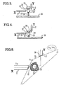
- Figure 3 is a schematic side elevation view of a key switch for the keyboard of the present invention illustrated in the inactive or light blocking position;
- Figure 4 is a view similar to Figure 3 but illustrating the key switch in the active or light coupling position; and
- Figure 5 is a schematic illustration of the hypothetical air prism formed at the juncture of the x-row and y-column of the fibers as a result of the cutting operation.
- Illustrated in Figure 1 is a schematic view of a keyboard matrix array in accordance with the present invention. As shown, the
matrix 10 comprises rows and columns of optical light conductingfiber elements 12 such for example as plastic threads or strands of generally circular or rectangular cross section. - Each thread or
strand 12 is wrapped or laid down between a y-column position and an x-row position. A light generating means 14 such for example as a light emitting diode (LED) is disposed at the row position of thestrands 12, while a light receptor means 16, such for example, a photo transistor or a photo diode is disposed at the column position of thestrands 12. - Energization of the light generating means 14 causes light to be transmitted over the bundle of
fiber strands 12 to be photoreceptor means 16. - As seen in Figure 2a each fiber is originally arranged in an L-shaped pattern (uncut) between the x and y position. By suitably slicing or cutting each fiber at a respective elbow or bend area 18 a
hypothetical air prism 20 is formed by virtue of the two facingangular cuts - It is noted that while the refractive index of air is N1, the refractive index N2 of the
truncated fiber element 12 is substantially greater than N1 so that the light that passes along the x portion will bend away from the base of the air prism and will couple across the air prism into the y portion of the fiber. So long as thesurfaces - In order to provide an operational keyboard device a series of
light blocking members 26 are employed, as shown in Figures 3 and 4. Eachmember 26 includes astem portion 28 and an identifyingkeytop 30.Stem portion 28 is provided with atransverse aperture 32 and means for retracting the key in response to key depression, as by the finger of an operator. The retracting means 34 may be a spring captivated within a cylindrical aperture in the lower portion of thestem 28. The spring abuts thebase member 36 of the keyboard so as to provide a vertically movable key switch. - By inserting the
key stem 28 with itsaperture 32 between the two angled cuts in each x-y fiber, a light blocking and unblocking member is formed. As seen in Figure 3 with thekey 26 raised to the inoperative position light cannot pass through theaperture 32 and thus no signal is provided with the respective y column receptor 16. However, depression ofkey 26, as shown in Figure 4 will bring theaperture 32 into coincidence or alignment with the two angledoptical surfaces hypothetical air prism 20 from theLED 14 to the photo receptor 16 causing a signal output to be generated through the associated operational electronics. - In the 4 x 4 fiber optic keyboard matrix illustrated in Figure 1, each key is individualized for identification. Thus for example if x2 row fibers are lighted and y fibers pick up light this indicates that
key number 9 is activated. If x3 row fibers are lighted and y2 picks up light then key e is activated. If x3 is lighted and y1 and y3 pick up light than keys d and f are activated and so on for all the keys depressed throughout the matrix above described. - There has thus been described a new, novel, useful and heretofore unobvious photo-optical keyboard structure which is inexpensive to fabricate and simple and efficient in use and operation. The concept is .completely feasible and can produce by means of automatic machinery which include:
- 1. Automatically organizing and mounting bundles of optical fibers in a desired matrix to form a keyboard layout.
- 2. Automatically cutting or slicing the fibers at strategic predetermined locations to form the desired air prisms across which the signal will be coupled as the key stem is raised or lowered, and
- 3. Automatically inserting light blocking and unblocking keys and locking them in position to form a keyboard key structure.
Claims (6)
Applications Claiming Priority (2)
| Application Number | Priority Date | Filing Date | Title |
|---|---|---|---|
| US35882582A | 1982-03-16 | 1982-03-16 | |
| US358825 | 1982-03-16 |
Publications (3)
| Publication Number | Publication Date |
|---|---|
| EP0089239A2 true EP0089239A2 (en) | 1983-09-21 |
| EP0089239A3 EP0089239A3 (en) | 1986-07-30 |
| EP0089239B1 EP0089239B1 (en) | 1989-01-25 |
Family
ID=23411202
Family Applications (1)
| Application Number | Title | Priority Date | Filing Date |
|---|---|---|---|
| EP19830301447 Expired EP0089239B1 (en) | 1982-03-16 | 1983-03-16 | Fiber wrap keyboard and switch |
Country Status (4)
| Country | Link |
|---|---|
| EP (1) | EP0089239B1 (en) |
| JP (1) | JPS59500191A (en) |
| DE (1) | DE3379077D1 (en) |
| WO (1) | WO1983003314A1 (en) |
Cited By (1)
| Publication number | Priority date | Publication date | Assignee | Title |
|---|---|---|---|---|
| WO1992022864A1 (en) * | 1991-06-08 | 1992-12-23 | Il Jin Corporation | A multipurpose optical intelligent key board apparatus |
Families Citing this family (2)
| Publication number | Priority date | Publication date | Assignee | Title |
|---|---|---|---|---|
| US9952719B2 (en) | 2012-05-24 | 2018-04-24 | Corning Incorporated | Waveguide-based touch system employing interference effects |
| US20140210770A1 (en) | 2012-10-04 | 2014-07-31 | Corning Incorporated | Pressure sensing touch systems and methods |
Citations (5)
| Publication number | Priority date | Publication date | Assignee | Title |
|---|---|---|---|---|
| US3648050A (en) * | 1970-08-06 | 1972-03-07 | Tuh Kai Koo | Optoelectronic data entry means having plurality of control means to direct part of radiation in channel from radiation source to output channel |
| US3856127A (en) * | 1972-11-24 | 1974-12-24 | U Halfon | Photo-optical keyboard |
| FR2238115A1 (en) * | 1973-07-17 | 1975-02-14 | Searle Russell | Domestic lighting unit - rays from bulb pass along transparent component to angled end reflector surface |
| DE2516171A1 (en) * | 1975-04-14 | 1976-10-21 | Rainer Dr Med Liedtke | Pushbutton switch for tripping optoelectronic couplings - generates switching pulses using light source and photodetector as contacts |
| US4013342A (en) * | 1975-12-19 | 1977-03-22 | Narodny Leo H | Keyboard using optical switching |
Family Cites Families (2)
| Publication number | Priority date | Publication date | Assignee | Title |
|---|---|---|---|---|
| US3787837A (en) * | 1971-04-19 | 1974-01-22 | Cogar Corp | Modular optical apparatus |
| US3937952A (en) * | 1972-09-22 | 1976-02-10 | National Research Development Corporation | Keyboard and switches for keyboards |
-
1983
- 1983-03-15 JP JP83501356A patent/JPS59500191A/en active Pending
- 1983-03-15 WO PCT/US1983/000344 patent/WO1983003314A1/en unknown
- 1983-03-16 DE DE8383301447T patent/DE3379077D1/en not_active Expired
- 1983-03-16 EP EP19830301447 patent/EP0089239B1/en not_active Expired
Patent Citations (5)
| Publication number | Priority date | Publication date | Assignee | Title |
|---|---|---|---|---|
| US3648050A (en) * | 1970-08-06 | 1972-03-07 | Tuh Kai Koo | Optoelectronic data entry means having plurality of control means to direct part of radiation in channel from radiation source to output channel |
| US3856127A (en) * | 1972-11-24 | 1974-12-24 | U Halfon | Photo-optical keyboard |
| FR2238115A1 (en) * | 1973-07-17 | 1975-02-14 | Searle Russell | Domestic lighting unit - rays from bulb pass along transparent component to angled end reflector surface |
| DE2516171A1 (en) * | 1975-04-14 | 1976-10-21 | Rainer Dr Med Liedtke | Pushbutton switch for tripping optoelectronic couplings - generates switching pulses using light source and photodetector as contacts |
| US4013342A (en) * | 1975-12-19 | 1977-03-22 | Narodny Leo H | Keyboard using optical switching |
Cited By (2)
| Publication number | Priority date | Publication date | Assignee | Title |
|---|---|---|---|---|
| WO1992022864A1 (en) * | 1991-06-08 | 1992-12-23 | Il Jin Corporation | A multipurpose optical intelligent key board apparatus |
| US5515045A (en) * | 1991-06-08 | 1996-05-07 | Iljin Corporation | Multipurpose optical intelligent key board apparatus |
Also Published As
| Publication number | Publication date |
|---|---|
| EP0089239A3 (en) | 1986-07-30 |
| WO1983003314A1 (en) | 1983-09-29 |
| DE3379077D1 (en) | 1989-03-02 |
| EP0089239B1 (en) | 1989-01-25 |
| JPS59500191A (en) | 1984-02-02 |
Similar Documents
| Publication | Publication Date | Title |
|---|---|---|
| US3982123A (en) | Optical fiber power taps | |
| US3936631A (en) | Optical fiber power tap | |
| US5260587A (en) | Optical semiconductor device array module with light shielding plate | |
| EP0089237B1 (en) | Single plane optical membrane switch and keyboard | |
| EP0887673A2 (en) | Self-aligned mechanical M x N optical switch | |
| US20050238290A1 (en) | Passive alignment connection for fiber optics | |
| JPH095653A (en) | Self-alignment type mechanical optical switch | |
| EP0289332A1 (en) | Optical device | |
| US4872739A (en) | Optical busbar | |
| US4950046A (en) | Fiber optic coupler | |
| KR20010041299A (en) | Connection system for optical redundancy | |
| EP0497011A1 (en) | Circuit board assembly | |
| EP0089235A2 (en) | Molded optical waveguide switching apparatus | |
| JP2010211240A (en) | Device having multiple optical fibers | |
| US6393174B1 (en) | Integrated fiber array optical switch using double-pass propagation and method of operation | |
| US6393175B1 (en) | Integrated fiber array optical switch and method of operation | |
| US4480183A (en) | Multi-plane optical membrane switch apparatus | |
| EP0089239A2 (en) | Fiber wrap keyboard and switch | |
| US6442322B1 (en) | Optical fiber management device | |
| EP1395864A2 (en) | High density optical fiber array | |
| US6618514B1 (en) | Passive pigtail attachment apparatus and method for planar lightwave circuits | |
| US4788161A (en) | Method of producing an end surface light emission type semiconductor device | |
| US6529653B1 (en) | System and method for orienting and positioning optical fibers | |
| EP0301702A2 (en) | Single mode star coupler | |
| US6529655B1 (en) | Frustrated total internal reflection optical switch using waveguides and method of operation |
Legal Events
| Date | Code | Title | Description |
|---|---|---|---|
| PUAI | Public reference made under article 153(3) epc to a published international application that has entered the european phase |
Free format text: ORIGINAL CODE: 0009012 |
|
| 17P | Request for examination filed |
Effective date: 19830319 |
|
| AK | Designated contracting states |
Designated state(s): BE DE FR GB NL SE |
|
| PUAL | Search report despatched |
Free format text: ORIGINAL CODE: 0009013 |
|
| AK | Designated contracting states |
Kind code of ref document: A3 Designated state(s): BE DE FR GB NL SE |
|
| RAP1 | Party data changed (applicant data changed or rights of an application transferred) |
Owner name: BURROUGHS CORPORATION (A DELAWARE CORPORATION) |
|
| RAP1 | Party data changed (applicant data changed or rights of an application transferred) |
Owner name: UNISYS CORPORATION |
|
| 17Q | First examination report despatched |
Effective date: 19870812 |
|
| GRAA | (expected) grant |
Free format text: ORIGINAL CODE: 0009210 |
|
| AK | Designated contracting states |
Kind code of ref document: B1 Designated state(s): BE DE FR GB NL SE |
|
| REF | Corresponds to: |
Ref document number: 3379077 Country of ref document: DE Date of ref document: 19890302 |
|
| ET | Fr: translation filed | ||
| PLBE | No opposition filed within time limit |
Free format text: ORIGINAL CODE: 0009261 |
|
| STAA | Information on the status of an ep patent application or granted ep patent |
Free format text: STATUS: NO OPPOSITION FILED WITHIN TIME LIMIT |
|
| 26N | No opposition filed | ||
| PGFP | Annual fee paid to national office [announced via postgrant information from national office to epo] |
Ref country code: SE Payment date: 19920221 Year of fee payment: 10 |
|
| PGFP | Annual fee paid to national office [announced via postgrant information from national office to epo] |
Ref country code: NL Payment date: 19920331 Year of fee payment: 10 |
|
| PGFP | Annual fee paid to national office [announced via postgrant information from national office to epo] |
Ref country code: BE Payment date: 19920409 Year of fee payment: 10 |
|
| PGFP | Annual fee paid to national office [announced via postgrant information from national office to epo] |
Ref country code: FR Payment date: 19921216 Year of fee payment: 11 |
|
| PG25 | Lapsed in a contracting state [announced via postgrant information from national office to epo] |
Ref country code: SE Effective date: 19930317 |
|
| PG25 | Lapsed in a contracting state [announced via postgrant information from national office to epo] |
Ref country code: BE Effective date: 19930331 |
|
| BERE | Be: lapsed |
Owner name: UNISYS CORP. Effective date: 19930331 |
|
| PG25 | Lapsed in a contracting state [announced via postgrant information from national office to epo] |
Ref country code: NL Effective date: 19931001 |
|
| NLV4 | Nl: lapsed or anulled due to non-payment of the annual fee | ||
| PGFP | Annual fee paid to national office [announced via postgrant information from national office to epo] |
Ref country code: GB Payment date: 19940207 Year of fee payment: 12 |
|
| PGFP | Annual fee paid to national office [announced via postgrant information from national office to epo] |
Ref country code: DE Payment date: 19940329 Year of fee payment: 12 |
|
| PG25 | Lapsed in a contracting state [announced via postgrant information from national office to epo] |
Ref country code: FR Effective date: 19941130 |
|
| REG | Reference to a national code |
Ref country code: FR Ref legal event code: ST |
|
| EUG | Se: european patent has lapsed |
Ref document number: 83301447.5 Effective date: 19931008 |
|
| PG25 | Lapsed in a contracting state [announced via postgrant information from national office to epo] |
Ref country code: GB Effective date: 19950316 |
|
| GBPC | Gb: european patent ceased through non-payment of renewal fee |
Effective date: 19950316 |
|
| PG25 | Lapsed in a contracting state [announced via postgrant information from national office to epo] |
Ref country code: DE Effective date: 19951201 |