EP0086578A2 - Vehicle axle suspension - Google Patents
Vehicle axle suspension Download PDFInfo
- Publication number
- EP0086578A2 EP0086578A2 EP83300363A EP83300363A EP0086578A2 EP 0086578 A2 EP0086578 A2 EP 0086578A2 EP 83300363 A EP83300363 A EP 83300363A EP 83300363 A EP83300363 A EP 83300363A EP 0086578 A2 EP0086578 A2 EP 0086578A2
- Authority
- EP
- European Patent Office
- Prior art keywords
- peaks
- valleys
- mounting
- layers
- reinforcement layers
- Prior art date
- Legal status (The legal status is an assumption and is not a legal conclusion. Google has not performed a legal analysis and makes no representation as to the accuracy of the status listed.)
- Granted
Links
Images

Classifications
-
- F—MECHANICAL ENGINEERING; LIGHTING; HEATING; WEAPONS; BLASTING
- F16—ENGINEERING ELEMENTS AND UNITS; GENERAL MEASURES FOR PRODUCING AND MAINTAINING EFFECTIVE FUNCTIONING OF MACHINES OR INSTALLATIONS; THERMAL INSULATION IN GENERAL
- F16F—SPRINGS; SHOCK-ABSORBERS; MEANS FOR DAMPING VIBRATION
- F16F1/00—Springs
- F16F1/36—Springs made of rubber or other material having high internal friction, e.g. thermoplastic elastomers
- F16F1/40—Springs made of rubber or other material having high internal friction, e.g. thermoplastic elastomers consisting of a stack of similar elements separated by non-elastic intermediate layers
- F16F1/403—Springs made of rubber or other material having high internal friction, e.g. thermoplastic elastomers consisting of a stack of similar elements separated by non-elastic intermediate layers characterised by the shape of the non-elastic interengaging parts between the elements
-
- B—PERFORMING OPERATIONS; TRANSPORTING
- B61—RAILWAYS
- B61F—RAIL VEHICLE SUSPENSIONS, e.g. UNDERFRAMES, BOGIES OR ARRANGEMENTS OF WHEEL AXLES; RAIL VEHICLES FOR USE ON TRACKS OF DIFFERENT WIDTH; PREVENTING DERAILING OF RAIL VEHICLES; WHEEL GUARDS, OBSTRUCTION REMOVERS OR THE LIKE FOR RAIL VEHICLES
- B61F5/00—Constructional details of bogies; Connections between bogies and vehicle underframes; Arrangements or devices for adjusting or allowing self-adjustment of wheel axles or bogies when rounding curves
- B61F5/26—Mounting or securing axle-boxes in vehicle or bogie underframes
- B61F5/30—Axle-boxes mounted for movement under spring control in vehicle or bogie underframes
- B61F5/305—Axle-boxes mounted for movement under spring control in vehicle or bogie underframes incorporating rubber springs
Definitions
- This invention relates to elastomeric mountings and in particular, though not exclusively to mountings for use as an alternative to conventional chevron type springs comprising an interleaved arrangement of angled metal plates and one or more layers of elastomeric material.
- a common application for chevron type springs is in railway vehicle suspensions where it is the practice resiliently to interconnect an axle box and bogie frame by means of a pair of chevron springs arranged in an inclined manner with the apex lines of the metal plates at a small angle to the vertical.
- a spring having, say, seven metal plates and six rubber interleaves, for the metal plates to vary progressively in shape from being relatively deep (in the line of the apex) and narrow at one end to shallow and broad at the other end.
- the relatively deep and narrow end plate is provided at an "inner" end of the spring, with the other plates and layers extending from those surfaces of the "inner” plate facing away from one another. With this variation in width the bending moments on the plates are kept substantially uniform.
- the variation in length, from deep to shallow, is such that there is a substantially similar bonded area between each plate and rubber layer, and this assists in avoiding unnecessary use of materials as well as providing the commonly required relatively large deflection capability in the direction of the apex line of the plate.
- the spring Whilst the above considerations lead to a spring design which is both economical and efficient in use of materials, the spring is of an irregular shape and not well adapted for use in situations where space is limited.
- the invention as claimed is intended to remedy these drawbacks. It provides a mounting for use as an alternative to conventional type chevron springs which is of compact shape without introducing an area susceptible to premature fatigue failure in the mounting by utilising a construction comprising a stack of elastomeric layers having substantially inextensible reinforcement layers interleaved between and bonded to the elastomeric layers in which the confronting surfaces of successive reinforcement layers are each of corrugated profile having a plurality of alternate peaks and valleys.
- the main advantage offered by the invention is that for a given load requirement the stress concentrations are more evenly distributed throughout the corrugated reinforcement layers of the mounting according to the present invention as compared with a chevron spring in which the reinforcement layers are of V-shaped cross-section and hence the fatigue life of the mounting is improved. Furthermore it is possible to obtain this even distribution of stress concentration in the mounting according to the present invention with reinforcement layers of identical shape and size with the result that for a given load requirement the mounting occupies a smaller space envelope than a comparable chevron spring thereby facilitating the incorporation of the mounting in a rail vehicle axle suspension where the space available for the mounting is limited.
- the corrugated shape may, for example, be a zig-zag shape in cross-section, i.e. a series of substantially straight portions angled relative to one another, or may comprise a series of curved portions having, for example, a sinusoidal type shape in cross-section.
- the confronting surfaces of successive reinforcement layers are arranged so that the peaks of one surface are aligned with the valleys of the other surface and vice versa.
- the peaks of one surface may lie within the valleys of the confronting surface but more preferably lie outside the valleys.
- the peaks and valleys are substantially straight and parallel to one another and more preferably are linear and continuous across the surface of the associated reinforcement layer.
- the peaks are of uniform cross-section and said valleys are preferably also of uniform cross-section, said cross-sections being taken normal to the longitudinal axis of the peaks and valleys.
- the reinforcement layers are of identical shape and size. All the layers may lie vertically above one another or the layers may be progressively offset laterally from one end of the mounting to the other i.e. arranged in echelon.
- the number of peaks and the distance between the peaks of any one surface may be selected to give a balanced construction in which different parts of the mounting are substantially equally stressed when the mounting is loaded respectively in each of its three mutually perpendicular principal directions.
- the elastomeric layer between a pair of confronting surfaces may be relieved in the vicinity of one or more peaks of the confronting surfaces, for example, it may be "cored" by drilling or moulding the elastomer so that the elastomer is formed with one or more holes extending through the elastomer parallel to and in the vicinity of one or more peaks. Coring may be employed to reduce stress concentration in the interleaving elastomer and reinforcement layers.
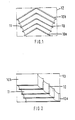
- a known chevron spring illustrated in Figures 1 and 2 of the accompanying drawings comprise five angled metal plates 10 of V-shape in cross-section having located therebetween and bonded thereto four rubber interleaving layers 11.
- the metal plates and rubber layers are arranged in echelon, when unstressed, as shown in Figure 2.
- An inner end plate 10a is of a relatively narrow and deep shape compared with an outer end plate lOb of relatively broad and shallow shape with the intermediate plates 10 of progressively varied intermediate dimensions such that each bonded surface area is substantially equal.
- Figures 1 and 2 are the outlines 12,13 of rectangles defining the limits of the spring shape in plan and side view respectively, and from these it will be seen that a significant proportion of the overall space envelope in each of said views is not occupied and usefully employed by components of the spring.
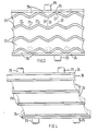
- FIG. 3 to 5 of the accompanying drawings there is illustrated a mounting in accordance with the present invention and comprising a stack of four metal plates 20 having three interleaving rubber layers 21 located therebetween. All the plates 20 are of identical size and shape, and likewise, the rubber layers are all of similar size and shape.
- the surfaces of the plates 20 are of a generally zig-zag shape having a plurality of inclined portions defining alternate peaks 22 and valleys 23 which are substantially straight in the direction of their length and extrend parallel to one another.
- the peaks 22 and valleys 23 are continuous across the surfaces of the plates 20 and are each of uniform cross-section, said cross-section being taken normal to the longitudinal axis of the peaks and valleys.
- the plates 20 are arranged so that the peaks 22 in the surface of one plate 20 are aligned with but lie outside the valleys 23 in the confronting surface of the adjacent plate 20.
- the apices of the peaks 22 of each surface lie in respective common places CP(one only shown) which extend parallel to the general plane GP of the plate and normal to the longitudinal axis of the mounting.
- each rubber layer may be cored or otherwise relieved in the vicinity of one or more peaks as shown in broken lines in Figure 3.
- Successive plates 20 and interleaving rubber layers 21 are progressively offset laterally ( Figures 4 and 5) from one end of the mounting to the other, i.e. arranged in echelon, when unstressed.
- the stack of four plates 20 and three rubber layers 21 is located between a pair of flat metal end plates 24 each provided with location studs 25.
- the spaces between the end plates 24 and the adjacent metal plates 20 are occupied by rubber segments 26 bonded to the plates.
- the optional coring of the rubber layers is believed to assist further in reducing angular movement between successive inclined portions of each of the metal plates 20.
- the metal plates are of similar shape and size, and likewise the rubber layers therebetween, it is to be understood that this is not essential to the main feature of the invention which is the provision of plates having a plurality of peaks and valleys so as to be of corrugated form.
- the invention also provides a mounting in which the successive plates may vary in overall shape substantially in the same manner as those of the conventional chevron spring illustrated in Figures 1 and 2, i.e. varying from narrow and deep at one end to broad and shallow at the other end of the spring.
- the distance between the peaks of each plate may be identical or may vary progressively from one plate to another depending on the overall characteristics required of the mounting.
- the spacing between peaks of each plate may increase progressively for successive plates such that imaginary lines drawn through corresponding peaks of successive plates are inclined relative to one another.
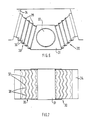
- FIG. 6 and 7 there is shown a railway vehicle suspension incorporating mountings 30 similar to the mounting described above with reference to Figures 3 to 5.
- the suspension comprises an axle box 31 having a central opening in which one end of an axle 32 is rotatably received and a pair of mountings 30 mounted fore and aft of the axle box 31 in the longitudinal direction of the vehicle and extending between the axle box and a bogie frame 34.
- Each mounting 30 is similar to that described with reference to Figures 3 to 5 comprising a stack of metal plates 35 having rubber layers 36 interleaved between and bonded to the plates 35.
- the plates 35 are of identical size and shape, likewise the rubber layers 36, and are progressively offset from one end of the spring to the other, i.e. arranged in echelon.
- the surfaces of the plates 35 are of zig-zag profile having alternate peaks 37 and valleys 38 which are substantially straight in the direction of their length and extend parallel to one another.
- the peaks 37 and valleys 38 are continuous across the surfaces of the plates 35 and are each of uniform cross-section, said cross-section being taken normal to the longitudinal axis of the peaks and valleys.
- the plates 35 are arranged so that the peaks 37 in the surface of one plate 35 are aligned with but lie outside the valleys 38 in the confronting surface of the adjacent plate 35.
- the mountings 30 extend upwardly and outwardly from the axle box 31 in a vee- arrangement with the longitudinal axes of the mountings inclined at equal and opposite angles to the vertical and horizontal.
- the rubber layers are loaded in compression and shear for loads applied vertically and longitudinally of the vehicle.
- the mountings 30 are arranged with the longitudinal axes of the peaks and valleys extending in a direction transverse to the direction in which the axle extends.
- the rubber layers are also loaded in compression and shear for loads applied laterally of the vehicle and the stiffness of the mountings in a direction parallel to the axle, i.e. transverse to the direction in which the peaks and valleys extend, is increased as compared with a mounting in which the layers are flat.
- the mountings 30 have characteristics similar to a chevron spring when installed in a suspension as above described but have the advantage of occupying a smaller space envelope for a given load requirement.
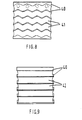
- a mounting in accordance with the invention is suitable for mounting with the plates and rubber interlayers extending substantially horizontally.
- One such type of application is as the side bearer mountings of a railway vehicle suspension, and a form of mounting for use in that type of application is shown in Figures 6 and 7.
- the mounting comprises a stack of six metal plates 40 having corrugated surfaces and five rubber interlayers 41 bonded to the corrugated surfaces of successive plates.
- the corrugated surfaces comprise alternate peaks and valleys constructed and arranged substantially as described previously with reference to the embodiment of Figures 3 to 5.
- the plates and layers are vertically aligned, and when in use in a side bearer application the metal plates extend generally in a horizontal plane.
- the outer end plates each have an inwardly directed face which is corrugated so that a corrugated shape rubber layer may be bonded directly to an end plate.
- each rubber layer may be cored or otherwise relieved in the vicinity of one or more peaks as shown in broken lines. The cores extending parallel to the peaks and valleys.
Landscapes
- Engineering & Computer Science (AREA)
- Mechanical Engineering (AREA)
- General Engineering & Computer Science (AREA)
- Architecture (AREA)
- Springs (AREA)
- Laminated Bodies (AREA)
Abstract
Description
- This invention relates to elastomeric mountings and in particular, though not exclusively to mountings for use as an alternative to conventional chevron type springs comprising an interleaved arrangement of angled metal plates and one or more layers of elastomeric material.
- A common application for chevron type springs is in railway vehicle suspensions where it is the practice resiliently to interconnect an axle box and bogie frame by means of a pair of chevron springs arranged in an inclined manner with the apex lines of the metal plates at a small angle to the vertical.
- To obtain maximum efficiency from a spring of this type it is desirable to provide the bext possible uniformity of stressing of the rubber and metal materials. Otherwise, to avoid premature fatigue failure at the points of maximum stress, it is necessary to form the spring larger than would be necessary if the materials were uniformly stressed. Apart from being inefficient in use of materials this can be a disadvantage in applications such as railway vehicle suspensions where space commonly is at a premium.
- To achieve a substantial degree of uniformity of stressing it is usual in a spring having, say, seven metal plates and six rubber interleaves, for the metal plates to vary progressively in shape from being relatively deep (in the line of the apex) and narrow at one end to shallow and broad at the other end. The relatively deep and narrow end plate is provided at an "inner" end of the spring, with the other plates and layers extending from those surfaces of the "inner" plate facing away from one another. With this variation in width the bending moments on the plates are kept substantially uniform. The variation in length, from deep to shallow, is such that there is a substantially similar bonded area between each plate and rubber layer, and this assists in avoiding unnecessary use of materials as well as providing the commonly required relatively large deflection capability in the direction of the apex line of the plate.
- Whilst the above considerations lead to a spring design which is both economical and efficient in use of materials, the spring is of an irregular shape and not well adapted for use in situations where space is limited.
- Where the requirement to satisfy space considerations is paramount it is the practice to employ springs in which the angled metal plates are of similar shape and size. In use this does, however, result in considerable and damaging stress concentrations at the apices of the metal plates and it is therefore necessary to replace the spring at relatively frequent intervals.
- The invention as claimed is intended to remedy these drawbacks. It provides a mounting for use as an alternative to conventional type chevron springs which is of compact shape without introducing an area susceptible to premature fatigue failure in the mounting by utilising a construction comprising a stack of elastomeric layers having substantially inextensible reinforcement layers interleaved between and bonded to the elastomeric layers in which the confronting surfaces of successive reinforcement layers are each of corrugated profile having a plurality of alternate peaks and valleys.
- The main advantage offered by the invention is that for a given load requirement the stress concentrations are more evenly distributed throughout the corrugated reinforcement layers of the mounting according to the present invention as compared with a chevron spring in which the reinforcement layers are of V-shaped cross-section and hence the fatigue life of the mounting is improved. Furthermore it is possible to obtain this even distribution of stress concentration in the mounting according to the present invention with reinforcement layers of identical shape and size with the result that for a given load requirement the mounting occupies a smaller space envelope than a comparable chevron spring thereby facilitating the incorporation of the mounting in a rail vehicle axle suspension where the space available for the mounting is limited.
- The corrugated shape may, for example, be a zig-zag shape in cross-section, i.e. a series of substantially straight portions angled relative to one another, or may comprise a series of curved portions having, for example, a sinusoidal type shape in cross-section.
- Preferably the confronting surfaces of successive reinforcement layers are arranged so that the peaks of one surface are aligned with the valleys of the other surface and vice versa.
- The peaks of one surface may lie within the valleys of the confronting surface but more preferably lie outside the valleys.
- Preferably the peaks and valleys are substantially straight and parallel to one another and more preferably are linear and continuous across the surface of the associated reinforcement layer.
- Preferably the peaks are of uniform cross-section and said valleys are preferably also of uniform cross-section, said cross-sections being taken normal to the longitudinal axis of the peaks and valleys.
- Preferably the reinforcement layers are of identical shape and size. All the layers may lie vertically above one another or the layers may be progressively offset laterally from one end of the mounting to the other i.e. arranged in echelon.
- The number of peaks and the distance between the peaks of any one surface may be selected to give a balanced construction in which different parts of the mounting are substantially equally stressed when the mounting is loaded respectively in each of its three mutually perpendicular principal directions.
- The elastomeric layer between a pair of confronting surfaces may be relieved in the vicinity of one or more peaks of the confronting surfaces, for example, it may be "cored" by drilling or moulding the elastomer so that the elastomer is formed with one or more holes extending through the elastomer parallel to and in the vicinity of one or more peaks. Coring may be employed to reduce stress concentration in the interleaving elastomer and reinforcement layers.
- The invention will now be described in more detail, by way of example only, with reference to the accompanying drawings in which:-
- Figure 1 is a plan view of a known chevron spring for use in a railway vehicle suspension;
- Figure 2 is a side view of the spring of Figure 1;
- Figure 3 is an end view of a mounting in accordance with the present invention for use in a railway vehicle suspension;
- Figure 4 is a side view of the mounting of Figure 3;
- Figure 5 is a plan view of the counting of Figures 3 and 4;
- Figure 6 is a side view of a railway vehicle suspension incorporating the mounting of Figures 3 to 5;
- Figure 7 is a plan view of the suspension shown in Figure 6;
- Figure 8 is a side view of another mounting in accordance with the present invention, and
- Figure 9 is an end view of the mounting shown in Figure 8.
- A known chevron spring illustrated in Figures 1 and 2 of the accompanying drawings comprise five
angled metal plates 10 of V-shape in cross-section having located therebetween and bonded thereto four rubberinterleaving layers 11. The metal plates and rubber layers are arranged in echelon, when unstressed, as shown in Figure 2. Aninner end plate 10a is of a relatively narrow and deep shape compared with an outer end plate lOb of relatively broad and shallow shape with theintermediate plates 10 of progressively varied intermediate dimensions such that each bonded surface area is substantially equal. Also shown in Figures 1 and 2 are theoutlines - Referring now to Figures 3 to 5 of the accompanying drawings there is illustrated a mounting in accordance with the present invention and comprising a stack of four
metal plates 20 having three interleavingrubber layers 21 located therebetween. All theplates 20 are of identical size and shape, and likewise, the rubber layers are all of similar size and shape. - The surfaces of the
plates 20 are of a generally zig-zag shape having a plurality of inclined portions definingalternate peaks 22 and valleys 23 which are substantially straight in the direction of their length and extrend parallel to one another. Thepeaks 22 and valleys 23 are continuous across the surfaces of theplates 20 and are each of uniform cross-section, said cross-section being taken normal to the longitudinal axis of the peaks and valleys. - The
plates 20 are arranged so that thepeaks 22 in the surface of oneplate 20 are aligned with but lie outside the valleys 23 in the confronting surface of theadjacent plate 20. The apices of thepeaks 22 of each surface lie in respective common places CP(one only shown) which extend parallel to the general plane GP of the plate and normal to the longitudinal axis of the mounting. Optionally each rubber layer may be cored or otherwise relieved in the vicinity of one or more peaks as shown in broken lines in Figure 3. -
Successive plates 20 and interleavingrubber layers 21 are progressively offset laterally (Figures 4 and 5) from one end of the mounting to the other, i.e. arranged in echelon, when unstressed. - The stack of four
plates 20 and threerubber layers 21 is located between a pair of flatmetal end plates 24 each provided withlocation studs 25. The spaces between theend plates 24 and theadjacent metal plates 20 are occupied byrubber segments 26 bonded to the plates. - In operation of the mounting it is found that by virtue of the substantially zig-zag profile of the confronting surfaces of the
plates 20 and therubber layers 21 therebetween there is achieved a relatively high transverse stiffness, i.e. resistance to relative movement of successive plates in a direction indicated by the arrow A (Figure 3) perpendicular to the direction in which the peaks extend without the need to provide metal plates and rubber layers of V-shaped cross-section as in a conventional chevron spring. - In respect of the previously experienced problems of high bending moment stresses on the metal plates it is believed that despite the absence of width variation this does not present a significant problem in the present construction. In particular;' it is believed that the bending moment stresses in the plates are less in the construction according to the present invention since by virtue of the zig-zag profile of the confronting surfaces of the
plates 20 and therubber layers 21 therebetween as shown in Figure 3, any localised stressing of the rubber material is less intense than in a conventional chevron spring. - In consequence of the reduced stress levals experienced by the plates having corrugated surfaces as opposed to similar size plates of simple V-shape in cross-section it is possible to selectively provide mountings having either thinner metal plates or a longer fatigue life for a given load requirement.
- The optional coring of the rubber layers is believed to assist further in reducing angular movement between successive inclined portions of each of the
metal plates 20. - From Figures 3 to 5 it will be appreciated that compared with a conventional chevron spring as illustrated in Figures 1 and 2, only a very small proportion of the space envelope defined by the overall dimensions of the mounting is not occupied and usefully employed by the components of the mounting.
- Whilst it is preferred that all the metal plates are of similar shape and size, and likewise the rubber layers therebetween, it is to be understood that this is not essential to the main feature of the invention which is the provision of plates having a plurality of peaks and valleys so as to be of corrugated form. Thus the invention also provides a mounting in which the successive plates may vary in overall shape substantially in the same manner as those of the conventional chevron spring illustrated in Figures 1 and 2, i.e. varying from narrow and deep at one end to broad and shallow at the other end of the spring.
- Irrespective of whether or not the corrugated plates are all of similar shape and size, the distance between the peaks of each plate may be identical or may vary progressively from one plate to another depending on the overall characteristics required of the mounting. The spacing between peaks of each plate may increase progressively for successive plates such that imaginary lines drawn through corresponding peaks of successive plates are inclined relative to one another.
- Referring now to Figures 6 and 7 there is shown a railway vehicle
suspension incorporating mountings 30 similar to the mounting described above with reference to Figures 3 to 5. - The suspension comprises an
axle box 31 having a central opening in which one end of anaxle 32 is rotatably received and a pair ofmountings 30 mounted fore and aft of theaxle box 31 in the longitudinal direction of the vehicle and extending between the axle box and abogie frame 34. Eachmounting 30 is similar to that described with reference to Figures 3 to 5 comprising a stack ofmetal plates 35 havingrubber layers 36 interleaved between and bonded to theplates 35. Theplates 35 are of identical size and shape, likewise therubber layers 36, and are progressively offset from one end of the spring to the other, i.e. arranged in echelon. The surfaces of theplates 35 are of zig-zag profile havingalternate peaks 37 andvalleys 38 which are substantially straight in the direction of their length and extend parallel to one another. Thepeaks 37 andvalleys 38 are continuous across the surfaces of theplates 35 and are each of uniform cross-section, said cross-section being taken normal to the longitudinal axis of the peaks and valleys. Theplates 35 are arranged so that thepeaks 37 in the surface of oneplate 35 are aligned with but lie outside thevalleys 38 in the confronting surface of theadjacent plate 35. - As shown in Figure 6 the
mountings 30 extend upwardly and outwardly from theaxle box 31 in a vee- arrangement with the longitudinal axes of the mountings inclined at equal and opposite angles to the vertical and horizontal. As a result the rubber layers are loaded in compression and shear for loads applied vertically and longitudinally of the vehicle. - As shown in Figure 7 the
mountings 30 are arranged with the longitudinal axes of the peaks and valleys extending in a direction transverse to the direction in which the axle extends. As a result the rubber layers are also loaded in compression and shear for loads applied laterally of the vehicle and the stiffness of the mountings in a direction parallel to the axle, i.e. transverse to the direction in which the peaks and valleys extend, is increased as compared with a mounting in which the layers are flat. - The
mountings 30 have characteristics similar to a chevron spring when installed in a suspension as above described but have the advantage of occupying a smaller space envelope for a given load requirement. - The scope of the invention is not restricted to mountings for use as alternatives to conventional chevron type springs. Thus, by way of further example, a mounting in accordance with the invention is suitable for mounting with the plates and rubber interlayers extending substantially horizontally. One such type of application is as the side bearer mountings of a railway vehicle suspension, and a form of mounting for use in that type of application is shown in Figures 6 and 7. The mounting comprises a stack of six
metal plates 40 having corrugated surfaces and fiverubber interlayers 41 bonded to the corrugated surfaces of successive plates. - The corrugated surfaces comprise alternate peaks and valleys constructed and arranged substantially as described previously with reference to the embodiment of Figures 3 to 5. In contrast to the echelon arrangement shown in Figure 4, in this construction the plates and layers are vertically aligned, and when in use in a side bearer application the metal plates extend generally in a horizontal plane. Also the outer end plates each have an inwardly directed face which is corrugated so that a corrugated shape rubber layer may be bonded directly to an end plate. Optionally each rubber layer may be cored or otherwise relieved in the vicinity of one or more peaks as shown in broken lines. The cores extending parallel to the peaks and valleys.
Claims (10)
Applications Claiming Priority (2)
| Application Number | Priority Date | Filing Date | Title |
|---|---|---|---|
| GB8204044 | 1982-02-11 | ||
| GB8204044 | 1982-02-11 |
Publications (3)
| Publication Number | Publication Date |
|---|---|
| EP0086578A2 true EP0086578A2 (en) | 1983-08-24 |
| EP0086578A3 EP0086578A3 (en) | 1983-11-16 |
| EP0086578B1 EP0086578B1 (en) | 1988-10-19 |
Family
ID=10528268
Family Applications (1)
| Application Number | Title | Priority Date | Filing Date |
|---|---|---|---|
| EP83300363A Expired EP0086578B1 (en) | 1982-02-11 | 1983-01-25 | Vehicle axle suspension |
Country Status (6)
| Country | Link |
|---|---|
| US (1) | US4589347A (en) |
| EP (1) | EP0086578B1 (en) |
| JP (1) | JPS58151241A (en) |
| CA (1) | CA1205497A (en) |
| DE (1) | DE3378264D1 (en) |
| GB (1) | GB2114706B (en) |
Cited By (8)
| Publication number | Priority date | Publication date | Assignee | Title |
|---|---|---|---|---|
| FR2663099A1 (en) * | 1990-06-07 | 1991-12-13 | Dunlop Ltd | ELASTIC SUPPORT COMPRISING AN ELASTOMER LAYER AND TWO END PIECES, IN PARTICULAR FOR A MARINE ENGINE. |
| EP0497461A2 (en) * | 1991-01-29 | 1992-08-05 | Lord Corporation | Elevated temperature elastomeric bearing |
| WO2001051330A1 (en) * | 2000-01-07 | 2001-07-19 | Lord Corporation | Lateral control mount |
| WO2001051331A1 (en) * | 2000-01-07 | 2001-07-19 | Lord Corporation | Lateral control mount |
| GB2423346B (en) * | 2003-10-23 | 2008-05-07 | Miller Herman Inc | Pixelated support structures and elements |
| US7740321B2 (en) | 2006-05-12 | 2010-06-22 | Herman Miller, Inc. | Suspended pixelated seating structure |
| US8128175B2 (en) | 2008-06-04 | 2012-03-06 | Herman Miller, Inc. | Suspension seating |
| US8691370B2 (en) | 2008-07-25 | 2014-04-08 | Herman Miller, Inc. | Multi-layered support structure |
Families Citing this family (17)
| Publication number | Priority date | Publication date | Assignee | Title |
|---|---|---|---|---|
| US4729694A (en) * | 1986-06-30 | 1988-03-08 | Lockheed Corporation | TLP marine riser tensioner |
| IT1221919B (en) * | 1987-03-31 | 1990-08-23 | Pirelli Accessori Ind | SUPPORTING BODY FOR SPRINGS FOR SUSPENSION OF RAILWAY WAGONS AND SIMILAR |
| US5842687A (en) * | 1997-04-25 | 1998-12-01 | Lord Corporation | Self-aligning vibration mount with compound-angled flexing elements |
| US6637345B1 (en) | 2002-10-11 | 2003-10-28 | Dana Corporation | Isolated axle mounting |
| US8302988B2 (en) * | 2008-03-10 | 2012-11-06 | Hendrickson Usa, L.L.C. | Suspension assembly with tie-plate |
| US9004512B2 (en) | 2011-07-08 | 2015-04-14 | Hendrickson Usa, L.L.C. | Shear spring useful for vehicle suspension |
| EP2729316B1 (en) | 2011-07-08 | 2016-02-03 | Hendrickson USA, L.L.C. | Vehicle suspension and improved method of assembly |
| CN102514587A (en) * | 2011-12-02 | 2012-06-27 | 南车眉山车辆有限公司 | Elastic pad of bearing saddle |
| USD700113S1 (en) | 2012-07-06 | 2014-02-25 | Hendrickson Usa, L.L.C. | Suspension assembly |
| USD699637S1 (en) | 2012-07-06 | 2014-02-18 | Hendrickson Usa, L.L.C. | Shear spring for a suspension |
| USD700112S1 (en) | 2012-07-06 | 2014-02-25 | Hendrickson Usa, L.L.C. | Progressive rate spring for a suspension |
| CN102829114A (en) * | 2012-08-28 | 2012-12-19 | 中国航空工业集团公司北京航空材料研究院 | Auxiliary rubber spring for automobile suspension |
| JP6038578B2 (en) * | 2012-10-03 | 2016-12-07 | 川崎重工業株式会社 | Railcar bogie with a shaft spring |
| US9085212B2 (en) | 2013-03-15 | 2015-07-21 | Hendrickson Usa, L.L.C. | Vehicle suspension |
| US9150071B2 (en) | 2013-07-25 | 2015-10-06 | Hendrickson Usa, L.L.C. | Frame hanger for vehicle suspension |
| US20170234397A1 (en) * | 2014-10-17 | 2017-08-17 | Bridgestone Corporation | Anti-vibration device |
| JPWO2022092067A1 (en) | 2020-10-30 | 2022-05-05 |
Citations (8)
| Publication number | Priority date | Publication date | Assignee | Title |
|---|---|---|---|---|
| BE552456A (en) * | ||||
| GB720365A (en) * | 1952-09-03 | 1954-12-15 | Metalastik Ltd | Improvements in or relating to resilient suspensions for vehicle axle-boxes |
| GB950695A (en) * | 1962-01-18 | 1964-02-26 | Ioco Ltd | Improvements in laminated pressure or cushioning pads |
| CH454940A (en) * | 1966-09-08 | 1968-04-30 | Rheinstahl Siegener Eisenbahnb | Axle suspension for rail vehicles |
| FR2067479A5 (en) * | 1969-11-05 | 1971-08-20 | Sncf | |
| DE1530164A1 (en) * | 1965-08-04 | 1972-03-30 | Rathgeber Ag Waggonfab Jos | Bogie for rail vehicles |
| GB1351138A (en) * | 1970-04-07 | 1974-04-24 | Dunlop Holdings Ltd | Springs |
| FR2363469A1 (en) * | 1976-08-31 | 1978-03-31 | Soule Ets Ind | Rail wagon bogie with filled PTFE bearings - has laminated rubber and metal springs for use on rough or short radius stack systems |
Family Cites Families (18)
| Publication number | Priority date | Publication date | Assignee | Title |
|---|---|---|---|---|
| GB362470A (en) * | 1930-07-29 | 1931-11-30 | Leopold Rado | Underlay for machines |
| US1930067A (en) * | 1931-10-15 | 1933-10-10 | Packard Motor Car Co | Motor vehicle |
| US2009059A (en) * | 1934-05-31 | 1935-07-23 | Fabreeka Products Company Inc | Railway device |
| GB487346A (en) * | 1936-02-15 | 1938-06-20 | Max Goldschmidt | Improvements in and relating to resilient supports or connections consisting of rubber and metal |
| GB522853A (en) * | 1938-12-20 | 1940-06-28 | Metalastik Ltd | Improvements in shock absorbing devices |
| US2713485A (en) * | 1952-05-28 | 1955-07-19 | Miner Inc W H | Rubber cushioning units for shock absorbers |
| GB753995A (en) * | 1952-09-03 | 1956-08-01 | Metalastik Ltd | Resilient mounting for rail and like vehicles |
| BE524185A (en) * | 1952-12-11 | |||
| US2873110A (en) * | 1954-10-25 | 1959-02-10 | Jonsson Einar | Torsion spring |
| US2893570A (en) * | 1956-07-03 | 1959-07-07 | Miner Inc W H | Draft gear for railway draft rigging |
| US3047163A (en) * | 1957-08-07 | 1962-07-31 | Acf Ind Inc | Cushioning assembly |
| GB877713A (en) * | 1959-07-09 | 1961-09-20 | Continental Gummi Werke Ag | Improvements in or relating to compression springs |
| US3429622A (en) * | 1967-03-06 | 1969-02-25 | Thiokol Chemical Corp | Flexible bearings and process for their manufacture |
| US3544415A (en) * | 1967-03-20 | 1970-12-01 | Conenco Canada Ltd | Reinforced elastomeric bearing |
| GB1391450A (en) * | 1971-09-22 | 1975-04-23 | Dunlop Ltd | Rubber springs |
| US3975007A (en) * | 1974-05-20 | 1976-08-17 | Ace Controls, Inc. | Resilient mounting structure |
| JPS5758049Y2 (en) * | 1978-03-03 | 1982-12-13 | ||
| JPS56116597A (en) * | 1980-02-15 | 1981-09-12 | Sanshin Ind Co Ltd | Connecting member with buffer function |
-
1983
- 1983-01-25 EP EP83300363A patent/EP0086578B1/en not_active Expired
- 1983-01-25 DE DE8383300363T patent/DE3378264D1/en not_active Expired
- 1983-02-02 US US06/463,080 patent/US4589347A/en not_active Expired - Fee Related
- 1983-02-08 GB GB08303396A patent/GB2114706B/en not_active Expired
- 1983-02-08 CA CA000421130A patent/CA1205497A/en not_active Expired
- 1983-02-10 JP JP58021410A patent/JPS58151241A/en active Granted
Patent Citations (8)
| Publication number | Priority date | Publication date | Assignee | Title |
|---|---|---|---|---|
| BE552456A (en) * | ||||
| GB720365A (en) * | 1952-09-03 | 1954-12-15 | Metalastik Ltd | Improvements in or relating to resilient suspensions for vehicle axle-boxes |
| GB950695A (en) * | 1962-01-18 | 1964-02-26 | Ioco Ltd | Improvements in laminated pressure or cushioning pads |
| DE1530164A1 (en) * | 1965-08-04 | 1972-03-30 | Rathgeber Ag Waggonfab Jos | Bogie for rail vehicles |
| CH454940A (en) * | 1966-09-08 | 1968-04-30 | Rheinstahl Siegener Eisenbahnb | Axle suspension for rail vehicles |
| FR2067479A5 (en) * | 1969-11-05 | 1971-08-20 | Sncf | |
| GB1351138A (en) * | 1970-04-07 | 1974-04-24 | Dunlop Holdings Ltd | Springs |
| FR2363469A1 (en) * | 1976-08-31 | 1978-03-31 | Soule Ets Ind | Rail wagon bogie with filled PTFE bearings - has laminated rubber and metal springs for use on rough or short radius stack systems |
Cited By (13)
| Publication number | Priority date | Publication date | Assignee | Title |
|---|---|---|---|---|
| FR2663099A1 (en) * | 1990-06-07 | 1991-12-13 | Dunlop Ltd | ELASTIC SUPPORT COMPRISING AN ELASTOMER LAYER AND TWO END PIECES, IN PARTICULAR FOR A MARINE ENGINE. |
| EP0497461A2 (en) * | 1991-01-29 | 1992-08-05 | Lord Corporation | Elevated temperature elastomeric bearing |
| EP0497461A3 (en) * | 1991-01-29 | 1992-10-21 | Lord Corporation | Elevated temperature elastomeric bearing |
| WO2001051330A1 (en) * | 2000-01-07 | 2001-07-19 | Lord Corporation | Lateral control mount |
| WO2001051331A1 (en) * | 2000-01-07 | 2001-07-19 | Lord Corporation | Lateral control mount |
| US6347588B1 (en) | 2000-01-07 | 2002-02-19 | Lord Corporation | Lateral control mount |
| GB2423346B (en) * | 2003-10-23 | 2008-05-07 | Miller Herman Inc | Pixelated support structures and elements |
| US7931257B2 (en) | 2003-10-23 | 2011-04-26 | Herman Miller, Inc. | Multilayer load bearing structure |
| US7740321B2 (en) | 2006-05-12 | 2010-06-22 | Herman Miller, Inc. | Suspended pixelated seating structure |
| US8186761B2 (en) | 2006-05-12 | 2012-05-29 | Herman Miller, Inc. | Suspended pixelated seating structure |
| US8128175B2 (en) | 2008-06-04 | 2012-03-06 | Herman Miller, Inc. | Suspension seating |
| US8691370B2 (en) | 2008-07-25 | 2014-04-08 | Herman Miller, Inc. | Multi-layered support structure |
| US9629467B2 (en) | 2008-07-25 | 2017-04-25 | Herman Miller, Inc. | Method for manufacturing a multi-layered support structure |
Also Published As
| Publication number | Publication date |
|---|---|
| US4589347A (en) | 1986-05-20 |
| GB8303396D0 (en) | 1983-03-16 |
| GB2114706A (en) | 1983-08-24 |
| CA1205497A (en) | 1986-06-03 |
| JPS58151241A (en) | 1983-09-08 |
| DE3378264D1 (en) | 1988-11-24 |
| GB2114706B (en) | 1985-10-09 |
| EP0086578B1 (en) | 1988-10-19 |
| EP0086578A3 (en) | 1983-11-16 |
| JPH0367903B2 (en) | 1991-10-24 |
Similar Documents
| Publication | Publication Date | Title |
|---|---|---|
| EP0086578B1 (en) | Vehicle axle suspension | |
| US3731913A (en) | Springs | |
| US3575403A (en) | Rubber-containing spring means | |
| CN100377947C (en) | Bearing shear pad | |
| US20120001373A1 (en) | Segmented elastomeric vibration mount with edge control | |
| GB2156947A (en) | Spring | |
| US9499022B2 (en) | Auxiliary rubber spring for automobile suspension | |
| EP0946833B1 (en) | Reinforced elastomeric spring | |
| US3830483A (en) | Springs | |
| CA1149433A (en) | Laminated bearings with dual stock layers | |
| US4435097A (en) | Laminated bearing structures | |
| US4537286A (en) | Elevator system | |
| CN102518726A (en) | Rubber spring damping device of heavy-load mining dumper balance suspension | |
| CA1095573A (en) | Laminated bearing structures | |
| EP1093548B1 (en) | Elastomeric mounting | |
| US6481637B1 (en) | Rail pad and method for strain attentuation | |
| US4282816A (en) | Elastomeric railway suspension | |
| CA1070721A (en) | Springs | |
| GB2352016A (en) | Elastomeric mounting for a vehicle suspension | |
| US7331534B2 (en) | Rail pad and method for strain attenuation | |
| EP4108952A1 (en) | Axle spring with laminated structure | |
| GB2244784A (en) | Elastomeric mounting | |
| US2187924A (en) | Flexible hanger | |
| GB2339258A (en) | Elastomeric mounting for a vehicle suspension | |
| CN113911158B (en) | Primary suspension spring for built-in axle box body bogie |
Legal Events
| Date | Code | Title | Description |
|---|---|---|---|
| PUAI | Public reference made under article 153(3) epc to a published international application that has entered the european phase |
Free format text: ORIGINAL CODE: 0009012 |
|
| AK | Designated contracting states |
Designated state(s): DE FR IT SE |
|
| PUAL | Search report despatched |
Free format text: ORIGINAL CODE: 0009013 |
|
| AK | Designated contracting states |
Designated state(s): DE FR IT SE |
|
| 17P | Request for examination filed |
Effective date: 19840512 |
|
| RAP1 | Party data changed (applicant data changed or rights of an application transferred) |
Owner name: DUNLOP LIMITED |
|
| GRAA | (expected) grant |
Free format text: ORIGINAL CODE: 0009210 |
|
| AK | Designated contracting states |
Kind code of ref document: B1 Designated state(s): DE FR IT SE |
|
| ITF | It: translation for a ep patent filed |
Owner name: GUZZI E RAVIZZA S.R.L. |
|
| REF | Corresponds to: |
Ref document number: 3378264 Country of ref document: DE Date of ref document: 19881124 |
|
| ITTA | It: last paid annual fee | ||
| ET | Fr: translation filed | ||
| PLBE | No opposition filed within time limit |
Free format text: ORIGINAL CODE: 0009261 |
|
| STAA | Information on the status of an ep patent application or granted ep patent |
Free format text: STATUS: NO OPPOSITION FILED WITHIN TIME LIMIT |
|
| 26N | No opposition filed | ||
| PGFP | Annual fee paid to national office [announced via postgrant information from national office to epo] |
Ref country code: FR Payment date: 19911028 Year of fee payment: 10 |
|
| PGFP | Annual fee paid to national office [announced via postgrant information from national office to epo] |
Ref country code: SE Payment date: 19911217 Year of fee payment: 10 |
|
| PGFP | Annual fee paid to national office [announced via postgrant information from national office to epo] |
Ref country code: DE Payment date: 19920331 Year of fee payment: 10 |
|
| PG25 | Lapsed in a contracting state [announced via postgrant information from national office to epo] |
Ref country code: SE Effective date: 19930126 |
|
| PG25 | Lapsed in a contracting state [announced via postgrant information from national office to epo] |
Ref country code: FR Effective date: 19930930 |
|
| PG25 | Lapsed in a contracting state [announced via postgrant information from national office to epo] |
Ref country code: DE Effective date: 19931001 |
|
| REG | Reference to a national code |
Ref country code: FR Ref legal event code: ST |
|
| EUG | Se: european patent has lapsed |
Ref document number: 83300363.5 Effective date: 19930810 |