EP0085575A2 - Power supply systems for use in radio communication systems - Google Patents
Power supply systems for use in radio communication systems Download PDFInfo
- Publication number
- EP0085575A2 EP0085575A2 EP83300513A EP83300513A EP0085575A2 EP 0085575 A2 EP0085575 A2 EP 0085575A2 EP 83300513 A EP83300513 A EP 83300513A EP 83300513 A EP83300513 A EP 83300513A EP 0085575 A2 EP0085575 A2 EP 0085575A2
- Authority
- EP
- European Patent Office
- Prior art keywords
- power supply
- base station
- output signal
- synchronizing signal
- repeater
- Prior art date
- Legal status (The legal status is an assumption and is not a legal conclusion. Google has not performed a legal analysis and makes no representation as to the accuracy of the status listed.)
- Granted
Links
Images


Classifications
-
- H—ELECTRICITY
- H04—ELECTRIC COMMUNICATION TECHNIQUE
- H04B—TRANSMISSION
- H04B7/00—Radio transmission systems, i.e. using radiation field
- H04B7/14—Relay systems
- H04B7/15—Active relay systems
- H04B7/155—Ground-based stations
-
- H—ELECTRICITY
- H04—ELECTRIC COMMUNICATION TECHNIQUE
- H04W—WIRELESS COMMUNICATION NETWORKS
- H04W52/00—Power management, e.g. TPC [Transmission Power Control], power saving or power classes
- H04W52/02—Power saving arrangements
- H04W52/0209—Power saving arrangements in terminal devices
- H04W52/0212—Power saving arrangements in terminal devices managed by the network, e.g. network or access point is master and terminal is slave
- H04W52/0216—Power saving arrangements in terminal devices managed by the network, e.g. network or access point is master and terminal is slave using a pre-established activity schedule, e.g. traffic indication frame
-
- H—ELECTRICITY
- H04—ELECTRIC COMMUNICATION TECHNIQUE
- H04W—WIRELESS COMMUNICATION NETWORKS
- H04W52/00—Power management, e.g. TPC [Transmission Power Control], power saving or power classes
- H04W52/02—Power saving arrangements
- H04W52/0209—Power saving arrangements in terminal devices
- H04W52/0225—Power saving arrangements in terminal devices using monitoring of external events, e.g. the presence of a signal
- H04W52/0229—Power saving arrangements in terminal devices using monitoring of external events, e.g. the presence of a signal where the received signal is a wanted signal
-
- Y—GENERAL TAGGING OF NEW TECHNOLOGICAL DEVELOPMENTS; GENERAL TAGGING OF CROSS-SECTIONAL TECHNOLOGIES SPANNING OVER SEVERAL SECTIONS OF THE IPC; TECHNICAL SUBJECTS COVERED BY FORMER USPC CROSS-REFERENCE ART COLLECTIONS [XRACs] AND DIGESTS
- Y02—TECHNOLOGIES OR APPLICATIONS FOR MITIGATION OR ADAPTATION AGAINST CLIMATE CHANGE
- Y02D—CLIMATE CHANGE MITIGATION TECHNOLOGIES IN INFORMATION AND COMMUNICATION TECHNOLOGIES [ICT], I.E. INFORMATION AND COMMUNICATION TECHNOLOGIES AIMING AT THE REDUCTION OF THEIR OWN ENERGY USE
- Y02D30/00—Reducing energy consumption in communication networks
- Y02D30/70—Reducing energy consumption in communication networks in wireless communication networks
Landscapes
- Engineering & Computer Science (AREA)
- Computer Networks & Wireless Communication (AREA)
- Signal Processing (AREA)
- Radio Relay Systems (AREA)
- Mobile Radio Communication Systems (AREA)
- Time-Division Multiplex Systems (AREA)
Abstract
Description
- This invention relates to a power supply system for receivers for use in a radio communication system, and more particularly a system of intermittently supplying power to radio receivers of repeaters and terminal devices of a radio communication system which performs a plurality of repeatings by using time division multiplexed system so as to save power consumption during a waiting time. Hereinafter, such a system of intermittently supplying power to receivers and transmitters is termed a battery saving system.
- Heretofore, application of the battery saving type power supply system was limited to a frequency division system. Because, in the frequency division multiplexed communication system (FDM system), the channels are divided according to allotted frequencies, different from a time division multiplexed communication system (TDM system), it is not necessary to timely detect a synchronizing signal for identifying channels so that the control of the battery saving type power supply can be simplified. However, in the case of the TDM system, the battery saving type power supply system must be synchronized such that receivers of all repeaters are ON/OFF controlled synchronously as will be explained later with reference to the drawings. This raises a problem inherent to the battery saving type power system based on the TDM system.
- In the accompanying drawings:
- Fig. 1 is a block diagram showing a radio repeating system;
- Fig. 2 is a timing chart showing the prior art battery saving type power supply system;
- Fig. 3 is a timing chart showing the battery saving type power supply system embodying the invention;
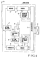
- Fig. 4 is a block diagram showing a base station embodying the invention;
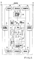
- Fig. 5 is a block diagram showing a repeater embodying the invention;
- Fig. 6 is a block diagram showing a terminal device embodying the invention; and
- Fig. 7 is a timing chart showing the battery saving type power supply system embodying the invention.
- Suppose now that
repeaters terminal device 4 of a radio communication system perform battery saving type power supply at independent periods. When there is a terminating call for theterminal device 4, a terminating call signal is sent from abase station 1 to stop the battery saving type power supply or intermittent power supply at therepeater 2 and the terminating call signal is transmitted from therepeater 2 to the repeater 3 to stop the battery saving type power supply thereat. Finally, the terminating call signal is transmitted to theterminal device 4 from therepeater 3, thus stopping the battery saving type power supply thereat. By successively transmitting the terminating call signal over a considerable time in this manner, it is possible to stop the battery saving type power supply of the entire communication system even when the devices are independently supplied with power according to the battery saving type power supply system. Similar operation is made when an originating call is made by the terminal device. In this manner, in the case of the FDM system, the battery saving type power supply can be readily controlled. - However, where the radio communication system shown in Fig. 1 is based on the TDM system, respective channels utilize the same frequency and the channels are discriminated from each other by the time positions or time slots of the signals. Accordingly, in order to correctly connect speech lines, all of the
repeaters terminal device 4 are required to detect at all times a synchronizing signal transmitted from thebase station 1 for identifying respective channels. Let us now consider a case whereinrepeaters terminal device 4 are independently operating according to the battery saving type power supply system. - If respective battery saving type power supply is executed at timings shown in Fig. 2 where section (a) illustrates a power supply voltage to a receiver in the
repeater 2, section (b) a receiver power supply voltage in therepeater 3 and section (c) a receiver an intermittent power supply voltage in theterminal device 4, all of the information would not be transmitted to theterminal device 4 from thebase station 1 so that synchronization is impossible. Accordingly, even when the terminal device wishes to originate, any originating call cannot be permitted because of the lack of synchronization. - Thus, in the case of a TDM system, it is necessary to synchronize the battery saving type power supply systems so that in all repeaters, receivers are ON/OFF controlled synchronously for positively transmitting a synchronizing signal to the terminal device from the base station. This means that, in the case of the TDM system too, it is necessary to synchronously supply power according to the battery saving type system.
- Accordingly, it is an object of this invention to provide a novel power supply system for a radio communication system capable of supplying power according to the battery saving type system even in a TDM system including a plurality of repeaters.
- In a particular embodiment of this invention, a specific synchronizing signal (hereinafter called BS-SYNC) is sent out from a base station and all devices in a communication system perform battery saving type power supply according to the synchronizing signal. Furthermore, received data are transmitted from a transmitter towards stations on the downstream side according to the synchronism of the battery saving type power supply. Respective stations start to supply power with the battery saving type by detecting the BS-SYNC signal and stop battery saving when absence of the BS-SYNC signal is detected.
- The power supply system of this embodiment is effective for a TDM system, especially for such a system including one or more repeaters because the TDM system operates in the form of a digital transmission and because the effectiveness of the digital transmission is possible where a regenerative repeating is possible, and deterioration of the quality of the communication is small.
- In other words, even with a small transmission output, the spacing between repeaters can be increased, and even when the number of repeaters increases, the quality of the communication signal does not become impaired. As a consequence, communication service can be made over a much wider area. The reason for using radio communication lies in that it is difficult to install communication wires or power supply lines from the standpoint of economical and geographical limitations. Especially, repeaters are installed on mountains or locations where commercial power line is difficult to avail. Solar cells or wind electric power generators generate only a small amount of power, so that an improved power supply system that consumes less power has been desired.
- The power supply system to be described in which only minimum necessary power is supplied during the idle time of the communication system greatly contributes to the saving of power in conjunction with the digital transmission.
- In a preferred embodiment, there is provided a power supply system for use in a radio communication system comprising a base station for transmitting and receiving radio signals, one or more repeating stations for repeating the radio signals, and a terminal station communicating with the base station through the repeater stations, in which the base station comprises means for transmitting synchronizing signal pulses at a predetermined period for effecting a battery saving type power supply, and each of the repeater station and terminal station comprises means, responsive to successive reception of a predetermined number of the synchronizing signal pulses, for effecting intermittent battery saving at a period substantially equal to the period of the synchronizing signal pulses during occurrence of the synchronizing signal pulses.
- Fig. 4 shows a block diagram of a base station in which external signals are received by a line concentrator 5 through an antenna 6, an antenna duplexer 7, a receiver 8 and a
decoder 9 while signals are sent to repeaters through anencoder 10, atransmitter 11, the antenna duplexer 7, and the antenna 6. Atelephone exchange 12 is connected to theline concentrator 5. An originatingcall signal detector 13 is connected between thedecoder 9 and theline concentrator 5, while a terminatingcall signal generator 14 is connected between theencoder 10 and theline concentrator 5. The outputs of thedetector 13 and the terminatingcall signal generator 14 are input to anOR gate circuit 15, and its output is applied to a synchronizingpulse generator 16 for battery saving. The synchronizingpulse generator 16 is connected to theencoder 10 via a BS-SYNC signal generator 17. - Fig. 5 is a block diagram showing a repeater embodying the invention, in which 18 and 19 show antennas, 20 and 21 antenna duplexers, 22 and 23 receivers, 24 and 25 transmitters, and 26 and 27 regenerators which are connected as shown.
Receivers 22 and 23, andtransmitters power source 29 through aswitch 28. An originatingcall signal detector 30 is connected to theregenerator 26, and the output of thedetector 30 is supplied to one input of anOR gate circuit 31 and to a reset terminal R of acounter 32. To theregenerator 27 is connected a BS-SYNC signal detector 33, the output thereof being supplied to the clock input of thecounter 32 and to one input of an AND gate circuit 34. The output of thecounter 32 is supplied to the other input of theAND gate circuit 34, the output thereof being supplied to the reset terminal R of a flip-flop circuit 35. The Q output of the flip-flop circuit 35 is supplied to the control terminal ofswitch 28 and to the other input of theOR gate circuit 31 via atimer 36. The output of theOR gate circuit 31 is supplied to the set terminal S of the flip-flop circuit 35. Apulse generator 100 includes theOR gate circuit 31,counter 32, ANDgate circuit 34, flip-flop circuit 35 andtimer 36. - Fig. 6 is a block diagram showing a terminal device embodying the invention in which 37 designates an antenna, 38 an antenna duplexer, 39 a transmitter, 40 a receiver, 41 and 42 regenerators, 43 a line concentrator, 44, 45 and 46 telephone sets.
- An originating
call signal generator 47 is connected between theline concentrator 43 and theregenerator 41. The output of the originatingcall signal generator 47 is supplied to one input of anOR gate circuit 48 and the reset terminal R of acounter 49. The transmitter 39 and the receiver 40 are connected to apower source 51 through aswitch 50. To theregenerator 42 is connected a BS-SYNC signal detector 52, the output thereof being supplied to the clock input of thecounter 49 and one input of anAND gate circuit 53 with other input supplied with the output of thecounter 49. The output of theAND gate circuit 53 is applied to the reset terminal R of a flip-flop circuit 54. The Q output of this flip-flop circuit 54 is connected to the control terminal of theswitch 50 and to the other input of theOR gate circuit 48 via atimer 55. A pulse generator 200 includes theOR gate circuit 48,counter 49, ANDgate circuit 53, flip-flop circuit 54 andtimer 55. - The system of this invention operates as follows. In Fig. 1, at the initial state, the
repeaters terminal device 4 operate to constantly supply power to the transmitter and receiver. When the speech lines are idle, the base station sends out a synchronizing signal (BS-SYNC signal) of a predetermined period for the battery saving type power supply, as shown at section (a) in Fig. 3. Illustrated at sections (b) through (d) in Fig. 3 are power supply voltage waveforms in therepeaters terminal device 4. Thus, when therepeaters terminal device 4 detect thrice, for example, the BS-SYNC signal at a correct period, the battery power saving type power supply is initiated. The interval of the ON/OFF operation of the power supply is predetermined such that the BS-SYNC signal sent out from the base station at a predetermind period must be received while the power is being supplied to the transmitters and receivers of therepeaters terminal device 4. More particularly, when therepeaters terminal device 4 continuously detect 3 times the BS-SYNC signal, the supply of power to the transmitters and receivers in each station is interrupted for a definite time (tl shown at (b) in Fig. 3) before the fourth BS-SYNC signal arrives. Thereafter, power is again supplied to detect the fourth BS-SYNC signal and in response to the detection, the source is again ON/OFF controlled for a predetermined time. This cycle of operation is repeated. Thus, the power is supplied intermittently to save power consumption. - Where no more BS-SYNC signal is detected, the battery saving type power supply is stopped until the signal is again continuously detected 3 times.
- The terminating call operation will now be described. At the base station, when a terminating call to the terminal device is detected, the transmission of the BS-SYNC signal is stopped at once. Accordingy, the battery saving in all stations is stopped. Thereafter, a speech line is connected to commence talking.
- In the case of an originating call, the
terminal device 4 sends out an originating call signal. This signal is transmitted to thebase station 1 while the transmitters and receivers of all stations are operating. As the base station detects the originating call signal, the BS-SYNC signal is terminated in the same manner as in a terminating call signal. As a result, the battery saving type power supply is stopped in all stations to connect a speech line. - When all speech lines are interrupted, the base station transmits again the BS-SYNC signal to resume the battery saving type power supply.
- The operations of the base station, the repeaters and the terminal device will be described in more detail.
- In Fig. 4, when both originating call and terminating call are not made, the synchronizing
pulse generator 16 for the battery saving type power supply operates, and in response to its output, the BS-SYNC signal generator 17 operates, and the BS-SYNC signal thus generated is sent to the repeaters and the terminal device throughencoder 10,transmitter 11, antenna duplexer 7 and antenna 6. When thetelephone exchange 12 produces a terminating call signal, it is detected by a ringer in theline concentrator 5, and the terminatingcall signal generator 14 produces terminating call signals for respective time divisioned time slots. When the terminating call signal is detected even in only one time slot, theOR gate circuit 15 is enabled to stop the operation of the synchronizingpulse generator 16 for the battery saving type power supply. - On the other hand, in the case of an originating call, the originating call signal transmitted from the
terminal device 4 via repeaters will be detected by the originatingcall signal detector 13 via antenna 6, antenna duplexer 7, receiver 8 anddecoder 9. In accordance with the output of the originatingcall signal detector 13, theline concentrator 5 connects a time slot in which the originating call has been commenced to thetelephone exchange 12. At the same time, theOR gate circuit 15 is enabled to stop the operation of synchronizingpulse generator 16 for the battery saving type power supply. - As described above, where there is an originating call or a terminating call, the transmission of the BS-SYNC signal is stopped, whereas when neither the originating call nor the terminating call is present, the transmission of the BS-SYNC signal continues.
- Turning now to Fig. 5, when neither the terminating call nor originating call are present,the base station transmits the BS-SYNC signal which is detected by the BS-
SYNC signal detector 33 viaantenna 19,antenna duplexer 21, receiver 23 andregenerator 27. The number of the BS-SYNC pulse output by thedetector 33 is counted by thecounter 32 and when its count reaches a predetermined value (three in an example shown in Fig. 3), its output is applied to the reset input R of the flip-flop circuit 35 via ANDgate circuit 34. - Thus, the flip-
flop circuit 35 is reset by the BS-SYNC pulse to apply an output to switch 28 for opening the same, thereby interrupting the power supply toreceivers 22 and 23, andtransmitters power source 29. At the same time, this output of the flip-flop circuit 35 starts operating thetimer 36. After a predetermined time interval t1 in Fig. 3 which is determined by the timer and which is slightly shorter than the period of the BS-SYNC signal, the timer produces an output to enable theOR gate circuit 31 for setting again the flip-flop circuit 35, whereby power is supplied again toreceivers 22 and 23 andtransmitters transmitter 25,antenna duplexer 20, andantenna 18. In this manner power is supplied to the repeaters by the battery saving type power supply system in accordance with the BS-SYNC signal sent from the base station. When a terminating call occurs, the battery saving is terminated since the BS-SYNC signal from the base station is stopped. - When an originating call occurs, the originating call signal is detected by the originating
call signal detector 30 viaantenna 18,antenna duplexer 20,receiver 22, andregenerator 26. The output produced by thedetector 30 enables theOR gate circuit 31 to set the flip-flop circuit 35, whereby theswitch 28 is closed to supply power to the transmitters and receivers from thepower source 29. At the same time, thecounter 32 is reset by the output of the originatingcall signal detector 30 and the source power is supplied to the transmitters and receivers for an interv sufficient for the count of thecounter 32 to reach a predetermined number. Consequently, the originating call signal will be transmitted to the base station viatransmitter 24,antenna duplexer 21 andantenna 19. Upon detection of the originating call signal, the base station immediately stops the generation of the BS-SYNC signal so that the battery saving type power supply of the repeaters is also stopped. - In Fig. 6, the terminal device also operates in the same manner as the repeaters. An originating call signal is produced by the originating
call signal generator 47 When the off-hook condition of the telephone sets 44, 45 and 46 is detected by theline concentrator 43. Thus, when either one of the telephone sets 44, 45 and .46 is off-hook, theOR gate circuit 48 is enabled by the output of the originatingcall signal generator 47 to set the flip-flop circuit 54. At the same time, since thecounter 49 is reset, power is supplied to the transmitter 39 and the receiver 40 from thepower source 51 for a sufficient time described above. During this interval, an originating call signal is sent to the base station so as to stop the battery saving type power supply in the same manner as in the repeaters. In the case of terminating a call too, since transmission of the BS-SYNC signal from the base station is stopped, the battery saving type power supply is stopped in the same manner as in the repeaters. - Referring to Fig. 7, the signal format of the BS-SYNC on time division-multiplex basis will be described in greater detail. Fig. 7 shows in sections (a) through (c) data signals respectively transmitted from the
base station 1, thefirst repeater 2, and the second repeater 3. A string of control time slots TS to TSn within one frame of the data signal is shown at section (d) in Fig. 7, and a string of signals contained in the time slot TSo is illustrated at (e) in Fig. 7. Especially, in the data signal at sections (a) to (c), a hatched frame contains a time slot TSo in which the BS-SYNC signal occurs and a non-hatched (blank) frame contains a time slot TS0 in which the BS-SYNC signal does not occur. - At the initial state, the receivers in the
repeaters terminal device 4 are always maintained in an operative state. As shown by a portion A in Fig. 7, the base station sends out the BS-SYNC signal of a definite period while any talking line is not used. - As shown by a portion ⑥ in Fig. 7, the BS-SYNC signal is arranged in a time slot TSo containing a frame synchronizing signal (portion ⑦), which time slot is periodically sent out from the base station. At each period, the data in that time slot is stored in a RAM, and the CPUs in the repeaters and the terminal device read the ddta in the RAM to detect the BS-SYNC signal when there is a BS-SYNC bit. When the BS-SYNC signal is detected 3 times at a correct period (portion ⑤), the battery saving type power supply is started and the next interval of supplying the power is determined such that the BS-SYNC signal sent at a predetermined period (portion CD) during the operation of the receiver will be exactly received (portion ②). As the BS-SYNC signal is not detected, the battery saving type power supply is stopped until this signal is detected again 3 times continuously.
- When a repeater detects a frame synchronizing signal (portion ⑦) contained in the control time slot, it repeats all data in the control time slot to a succeeding repeater. In other time slots, a sub-frame synchronizing signal is detected to be repeated in the same manner. As described above, the repeating operation continues until the BS-SYNC signal is detected three times, so that a control time slot where the BS-SYNC signal bit is raised is sent at least three times to any station. Accordingly, as soon as the frame synchronizing signal is detected under the supply of power a predetermined time after initiation of the battery saving, the repeating operation is initiated which continues until the BS-SYNC signal is detected again three times.
- At first let us consider a terminating call operation. When arrival of a terminating call signal is detected at the terminal device, the base station immediately stops the BS-SYNC signal (portion ③). This stops the battery saving type power supply in all stations. After that, a talking line is connected, permitting talking.
- In the case of an originating call, the terminal device sends out an originating call signal which is transmitted to the base station while the receivers of all stations are operating. When the base station detects the originating call signal, it stops transmission of the BS-SYNC signal in the same manner as in the case of terminating call, with the result that the battery saving type power supply in all stations is stopped and the talking line is connected.
- When all talking lines are interrupted, the base station transmits again the BS-SYNC signal to resume the battery saving type power supply (portion ④).
- As described above, a BS-SYNC signal is transmitted at a definite period from a base station, and repeaters and a terminal device perform the battery saving type power supply in synchronism with the BS-SYNC signal. According to this system, the battery saving type power supply is possible even in a TDM system including a plurality of repeaters.
- Furthermore, so long as the communication system is of the time division type, this invention is applicable to either the digital or the analog type. The BS-SYNC signal may be of any type of signal format.
Claims (7)
Applications Claiming Priority (2)
| Application Number | Priority Date | Filing Date | Title |
|---|---|---|---|
| JP57014459A JPS58131829A (en) | 1982-02-01 | 1982-02-01 | Radio relay system |
| JP14459/82 | 1982-02-01 |
Publications (3)
| Publication Number | Publication Date |
|---|---|
| EP0085575A2 true EP0085575A2 (en) | 1983-08-10 |
| EP0085575A3 EP0085575A3 (en) | 1984-10-03 |
| EP0085575B1 EP0085575B1 (en) | 1987-05-13 |
Family
ID=11861626
Family Applications (1)
| Application Number | Title | Priority Date | Filing Date |
|---|---|---|---|
| EP83300513A Expired EP0085575B1 (en) | 1982-02-01 | 1983-02-01 | Power supply systems for use in radio communication systems |
Country Status (5)
| Country | Link |
|---|---|
| US (1) | US4509199A (en) |
| EP (1) | EP0085575B1 (en) |
| JP (1) | JPS58131829A (en) |
| AU (1) | AU549599B2 (en) |
| CA (1) | CA1198168A (en) |
Cited By (4)
| Publication number | Priority date | Publication date | Assignee | Title |
|---|---|---|---|---|
| EP0132406A2 (en) * | 1983-07-25 | 1985-01-30 | Nec Corporation | Power saving system for time-division multiple access radiocommunication network |
| EP0245024A2 (en) * | 1986-05-06 | 1987-11-11 | Nec Corporation | Radio communication system with power saving disablement prior to call handling processes |
| DE19649855A1 (en) * | 1996-12-02 | 1998-06-04 | Deutsche Telekom Mobil | Repeater for radio signals |
| DE19649854A1 (en) * | 1996-12-02 | 1998-06-04 | Deutsche Telekom Mobil | Repeater unit for radio signals |
Families Citing this family (28)
| Publication number | Priority date | Publication date | Assignee | Title |
|---|---|---|---|---|
| JPS60182825A (en) * | 1984-02-29 | 1985-09-18 | Nec Corp | Radiotelephony system |
| FR2574201B1 (en) * | 1984-11-30 | 1987-04-24 | Cit Alcatel | REMOTE SIGNALING METHOD AND DEVICE FOR A DIGITAL TRANSMISSION LINK |
| US4837788A (en) * | 1985-11-08 | 1989-06-06 | Ford Aerospace & Communications Corporation | Repeater for extending local area networks |
| JPH0683085B2 (en) * | 1986-03-26 | 1994-10-19 | ソニー株式会社 | Transmitter |
| US4804954A (en) * | 1987-04-30 | 1989-02-14 | Motorola, Inc. | Battery saving method for portable communications receivers |
| IL85558A (en) * | 1987-04-30 | 1992-01-15 | Motorola Inc | Personal message receiving device with separate information presentation means |
| US4839645A (en) * | 1987-08-06 | 1989-06-13 | Lill Thomas M | Weather data transmitting system |
| US4850493A (en) * | 1988-06-20 | 1989-07-25 | Hoover Universal, Inc. | Blow molded bottle with self-supporting base reinforced by hollow ribs |
| US5150361A (en) * | 1989-01-23 | 1992-09-22 | Motorola, Inc. | Energy saving protocol for a TDM radio |
| US4964121A (en) * | 1989-08-30 | 1990-10-16 | Motorola, Inc. | Battery saver for a TDM system |
| US5584048A (en) * | 1990-08-17 | 1996-12-10 | Motorola, Inc. | Beacon based packet radio standby energy saver |
| JPH04328919A (en) * | 1991-04-26 | 1992-11-17 | Fujitsu Ltd | Radio calling signal system |
| NZ255617A (en) * | 1992-09-04 | 1996-11-26 | Ericsson Telefon Ab L M | Tdma digital radio: measuring path loss and setting transmission power accordingly |
| US5388101A (en) * | 1992-10-26 | 1995-02-07 | Eon Corporation | Interactive nationwide data service communication system for stationary and mobile battery operated subscriber units |
| AU672054B2 (en) * | 1992-12-30 | 1996-09-19 | Radio Communication Systems Ltd. | Bothway RF repeater for personal communications systems |
| US6775531B1 (en) * | 1994-07-21 | 2004-08-10 | Interdigital Technology Corporation | Subscriber terminal temperature regulation |
| US6243399B1 (en) | 1994-07-21 | 2001-06-05 | Interdigital Technology Corporation | Ring signal generator |
| EP1320249B1 (en) | 1994-07-21 | 2007-03-14 | Interdigital Technology Corporation | Ringing signal generator |
| US6132306A (en) * | 1995-09-06 | 2000-10-17 | Cisco Systems, Inc. | Cellular communication system with dedicated repeater channels |
| US6081733A (en) * | 1997-04-16 | 2000-06-27 | Motorola, Inc. | Communication control apparatus and method |
| JP3119605B2 (en) * | 1997-10-28 | 2000-12-25 | 埼玉日本電気株式会社 | Wireless base station |
| JP3257485B2 (en) * | 1997-11-19 | 2002-02-18 | 三菱マテリアル株式会社 | Communication system and communication method |
| US6339585B1 (en) * | 1998-05-05 | 2002-01-15 | Philips Electronics North America Corp. | Error-recovery mechanism using a temporary forwarder in a wireless-ATM network |
| US6690657B1 (en) | 2000-02-25 | 2004-02-10 | Berkeley Concept Research Corporation | Multichannel distributed wireless repeater network |
| US8200782B2 (en) * | 2005-04-29 | 2012-06-12 | Hewlett-Packard Development Company, L.P. | Communication with a mobile device |
| KR101273683B1 (en) * | 2009-01-29 | 2013-06-12 | 후지쯔 가부시끼가이샤 | Wireless communication system |
| WO2010106879A1 (en) * | 2009-03-16 | 2010-09-23 | 日本電気株式会社 | Mobile communication system and mobile communication method |
| US10462738B1 (en) | 2018-07-24 | 2019-10-29 | Motorola Solutions, Inc. | Base station device with reduced power consumption and method thereof |
Citations (2)
| Publication number | Priority date | Publication date | Assignee | Title |
|---|---|---|---|---|
| GB2072908A (en) * | 1980-03-28 | 1981-10-07 | Nippon Electric Co | Digital radio paging communication system |
| JPS56165425A (en) * | 1980-05-16 | 1981-12-19 | Meisei Electric Co Ltd | Power supplying system of electric machinery |
Family Cites Families (4)
| Publication number | Priority date | Publication date | Assignee | Title |
|---|---|---|---|---|
| US3049709A (en) * | 1957-12-27 | 1962-08-14 | Jr Lockwood Rianhard | Remote control actuated chemical-nuclear powered communication system |
| US3499985A (en) * | 1967-03-02 | 1970-03-10 | Us Navy | Two-way pulse repeater |
| JPS5792932A (en) * | 1980-12-01 | 1982-06-09 | Nec Corp | Selective calling receiver with display |
| US4449248A (en) * | 1982-02-01 | 1984-05-15 | General Electric Company | Battery saving radio circuit and system |
-
1982
- 1982-02-01 JP JP57014459A patent/JPS58131829A/en active Granted
-
1983
- 1983-01-31 US US06/462,343 patent/US4509199A/en not_active Expired - Lifetime
- 1983-02-01 EP EP83300513A patent/EP0085575B1/en not_active Expired
- 1983-02-01 AU AU10966/83A patent/AU549599B2/en not_active Expired
- 1983-02-01 CA CA000420698A patent/CA1198168A/en not_active Expired
Patent Citations (2)
| Publication number | Priority date | Publication date | Assignee | Title |
|---|---|---|---|---|
| GB2072908A (en) * | 1980-03-28 | 1981-10-07 | Nippon Electric Co | Digital radio paging communication system |
| JPS56165425A (en) * | 1980-05-16 | 1981-12-19 | Meisei Electric Co Ltd | Power supplying system of electric machinery |
Non-Patent Citations (1)
| Title |
|---|
| PATENTS ABSTRACTS OF JAPAN, vol. 6, no. 52(E-100)(930), 7th April 1982; & JP-A-56 165 425 (MEISEI DENKI K.K.) 19-12-1981, (Cat. A) * |
Cited By (9)
| Publication number | Priority date | Publication date | Assignee | Title |
|---|---|---|---|---|
| EP0132406A2 (en) * | 1983-07-25 | 1985-01-30 | Nec Corporation | Power saving system for time-division multiple access radiocommunication network |
| EP0132406A3 (en) * | 1983-07-25 | 1987-09-16 | Nec Corporation | Power saving system for time-division multiple access radiocommunication network |
| EP0245024A2 (en) * | 1986-05-06 | 1987-11-11 | Nec Corporation | Radio communication system with power saving disablement prior to call handling processes |
| EP0245024A3 (en) * | 1986-05-06 | 1989-08-09 | Nec Corporation | Radio communication system with power saving disablement prior to call handling processes |
| DE19649855A1 (en) * | 1996-12-02 | 1998-06-04 | Deutsche Telekom Mobil | Repeater for radio signals |
| DE19649854A1 (en) * | 1996-12-02 | 1998-06-04 | Deutsche Telekom Mobil | Repeater unit for radio signals |
| US6459881B1 (en) | 1996-12-02 | 2002-10-01 | T. Mobile Deutschland Gmbh | Repeater for radio signals |
| DE19649855B4 (en) * | 1996-12-02 | 2004-08-05 | T-Mobile Deutschland Gmbh | Repeater for radio signals |
| DE19649854B4 (en) * | 1996-12-02 | 2013-07-18 | T-Mobile Deutschland Gmbh | Repeater for radio signals |
Also Published As
| Publication number | Publication date |
|---|---|
| CA1198168A (en) | 1985-12-17 |
| AU549599B2 (en) | 1986-01-30 |
| AU1096683A (en) | 1984-01-05 |
| JPS632504B2 (en) | 1988-01-19 |
| EP0085575B1 (en) | 1987-05-13 |
| JPS58131829A (en) | 1983-08-05 |
| EP0085575A3 (en) | 1984-10-03 |
| US4509199A (en) | 1985-04-02 |
Similar Documents
| Publication | Publication Date | Title |
|---|---|---|
| EP0085575B1 (en) | Power supply systems for use in radio communication systems | |
| EP0132406B1 (en) | Power saving system for time-division multiple access radiocommunication network | |
| EP0511861B1 (en) | Digital mobile station using presettable timeslot counter for compensating for propagation delay time | |
| CA1257653A (en) | Radio communication system with power saving disablement prior to call handling processes | |
| JP2944113B2 (en) | Battery saving system | |
| US4049908A (en) | Method and apparatus for digital data transmission | |
| CA2321531A1 (en) | Method and system for transferring data | |
| JPH07193859A (en) | Inter-base station tdma frame synchronization system in mobile communication | |
| JP3254874B2 (en) | Digital cordless telephone equipment | |
| JPH10145847A (en) | Method and device for synchronizing frame | |
| JPS61172442A (en) | Radio relay system | |
| JP2669891B2 (en) | Intermittent reception control method in mobile communication | |
| JP2806091B2 (en) | Battery saving method | |
| JPH06303182A (en) | Inter-office phase synchronizing system and device used for this | |
| JP2891011B2 (en) | Transceiver | |
| JPH0575523A (en) | Intermittent reception system | |
| JP3498282B2 (en) | Connection device for digital cordless telephone equipment | |
| JP3018376B2 (en) | Wireless relay system | |
| JPS5934019B2 (en) | mobile radio telephone system | |
| JP2000023265A (en) | Connector for digital cordless telephone system | |
| JPH06103850B2 (en) | Control channel method in mobile communication | |
| JPS591017B2 (en) | Wireless receiver battery saving method | |
| JPS5840858B2 (en) | Time division multiple access satellite communication equipment | |
| JPH0555974A (en) | Transmission timing control circuit | |
| JPH0369454B2 (en) |
Legal Events
| Date | Code | Title | Description |
|---|---|---|---|
| PUAI | Public reference made under article 153(3) epc to a published international application that has entered the european phase |
Free format text: ORIGINAL CODE: 0009012 |
|
| AK | Designated contracting states |
Designated state(s): FR GB NL |
|
| RAP1 | Party data changed (applicant data changed or rights of an application transferred) |
Owner name: NEC CORPORATION |
|
| PUAL | Search report despatched |
Free format text: ORIGINAL CODE: 0009013 |
|
| AK | Designated contracting states |
Designated state(s): FR GB NL |
|
| 17P | Request for examination filed |
Effective date: 19840924 |
|
| GRAA | (expected) grant |
Free format text: ORIGINAL CODE: 0009210 |
|
| AK | Designated contracting states |
Kind code of ref document: B1 Designated state(s): FR GB NL |
|
| ET | Fr: translation filed | ||
| PLBE | No opposition filed within time limit |
Free format text: ORIGINAL CODE: 0009261 |
|
| STAA | Information on the status of an ep patent application or granted ep patent |
Free format text: STATUS: NO OPPOSITION FILED WITHIN TIME LIMIT |
|
| 26N | No opposition filed | ||
| REG | Reference to a national code |
Ref country code: GB Ref legal event code: IF02 |
|
| PGFP | Annual fee paid to national office [announced via postgrant information from national office to epo] |
Ref country code: GB Payment date: 20020130 Year of fee payment: 20 |
|
| PGFP | Annual fee paid to national office [announced via postgrant information from national office to epo] |
Ref country code: FR Payment date: 20020212 Year of fee payment: 20 |
|
| PGFP | Annual fee paid to national office [announced via postgrant information from national office to epo] |
Ref country code: NL Payment date: 20020228 Year of fee payment: 20 |
|
| PG25 | Lapsed in a contracting state [announced via postgrant information from national office to epo] |
Ref country code: GB Free format text: LAPSE BECAUSE OF EXPIRATION OF PROTECTION Effective date: 20030131 |
|
| PG25 | Lapsed in a contracting state [announced via postgrant information from national office to epo] |
Ref country code: NL Free format text: LAPSE BECAUSE OF EXPIRATION OF PROTECTION Effective date: 20030201 |
|
| REG | Reference to a national code |
Ref country code: GB Ref legal event code: PE20 Effective date: 20030131 |
|
| NLV7 | Nl: ceased due to reaching the maximum lifetime of a patent |
Effective date: 20030201 |