EP0084352A2 - Electronic door locking system for an automotive vehicle - Google Patents
Electronic door locking system for an automotive vehicle Download PDFInfo
- Publication number
- EP0084352A2 EP0084352A2 EP83100252A EP83100252A EP0084352A2 EP 0084352 A2 EP0084352 A2 EP 0084352A2 EP 83100252 A EP83100252 A EP 83100252A EP 83100252 A EP83100252 A EP 83100252A EP 0084352 A2 EP0084352 A2 EP 0084352A2
- Authority
- EP
- European Patent Office
- Prior art keywords
- signal
- vehicle
- response
- command signal
- door
- Prior art date
- Legal status (The legal status is an assumption and is not a legal conclusion. Google has not performed a legal analysis and makes no representation as to the accuracy of the status listed.)
- Granted
Links
Images
Classifications
-
- G—PHYSICS
- G07—CHECKING-DEVICES
- G07C—TIME OR ATTENDANCE REGISTERS; REGISTERING OR INDICATING THE WORKING OF MACHINES; GENERATING RANDOM NUMBERS; VOTING OR LOTTERY APPARATUS; ARRANGEMENTS, SYSTEMS OR APPARATUS FOR CHECKING NOT PROVIDED FOR ELSEWHERE
- G07C9/00—Individual registration on entry or exit
- G07C9/00174—Electronically operated locks; Circuits therefor; Nonmechanical keys therefor, e.g. passive or active electrical keys or other data carriers without mechanical keys
- G07C9/00658—Electronically operated locks; Circuits therefor; Nonmechanical keys therefor, e.g. passive or active electrical keys or other data carriers without mechanical keys operated by passive electrical keys
- G07C9/00674—Electronically operated locks; Circuits therefor; Nonmechanical keys therefor, e.g. passive or active electrical keys or other data carriers without mechanical keys operated by passive electrical keys with switch-buttons
- G07C9/0069—Electronically operated locks; Circuits therefor; Nonmechanical keys therefor, e.g. passive or active electrical keys or other data carriers without mechanical keys operated by passive electrical keys with switch-buttons actuated in a predetermined sequence
Definitions
- the present invention relates generally to an electronic push-button type door locking device for an automotive vehicle, and more particularly to an electronic door locking system by which vehicle doors can be locked or unlocked when the driver depresses a plurality of push-button type switches in accordance with a predetermined code.
- an electronic push-button type door locking system for an automotive vehicle, by which vehicle doors can be locked or unlocked when the driver depresses a plurality of push-button type switches installed at an appropriate position on the outside of an automotive vehicle in accordance with a predetermined code.
- an electronic vehicle door locking system as described above is used to lock or unlock the doors, since the vehicle doors can be locked or unlocked by the driver without using the ignition key, it is very convenient for the driver, in particular, when the vehicle is left parked.
- the devices or lights described above are, for instance, a power-operated car-radio antenna, small lights (or dimmered headlights), a room light, a device for locking the trunk room or the console box, a device for closing the side door windows or the sunroof, etc.
- an electronic door locking system for an automotive vehicle in which devices or lights now in operation or kept turned on or left unlocked or opened dangerously or unsafely within the passenger compartment can be turned off or returned to their original disabled conditions in response to a locking signal generated whenever the driver locks the vehicle doors by depressing a plurality of push-button type switches installed at an appropriate position on the outside of an automotive vehicle in accordance with a predetermined code.
- the electronic door locking system even if the driver locks the vehicle doors and leaves the vehicle without disabling or turning off vehicle devices, when the vehicle doors are locked by depressing the push-button switches in accordance with the predetermined code, the vehicle devices are automatically returned into their original disabled conditions and the vehicle can be parked safely.
- the electronic door locking system for an automotive vehicle comprises means for actuating vehicle devices to their original disabled conditions in response to the lock command signal generated whenever the driver locks the vehicle doors, in addition to the door locking system for an automotive vehicle.
- the vehicle device actuating means comprises, for instance, a timer unit for actuating the vehicle device for a predetermined time period, a switching element, a relay, an actuator, etc.
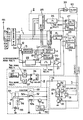
- the figure is a schematic block diagram of an embodiment of the electronic door locking system according to the present invention.
- the system according to the present invention can roughly be divided into five sections: a door unlocking command signal generating section 1, a door locking command signal generating section 2, a door lock/unlock actuating section 3, and an ignition key sensor section 4, and a vehicle device actuating section 5 closely related to the . present invention.
- the reference numerals 10a-10e denote a plurality of push-button type switches arranged at an appropriate position on the outer surface of a vehicle door.
- a specific sequence of numerals such as the five digits "2-1-3-5-4" are used; while to lock the vehicle doors, a single specific numeral, such as the digit "2" (the first of the above five digits) is used.
- the reference numeral 11 denotes a octal-binary code converter (referred to as O-B converter hereinafter) for converting the octal code designated by the push-button switches lOa-lOe into the corresponding three-bit binary code.
- the reference numeral 12 denotes a first OR gate for generating a H-voltage level output signal whenever the O- B converter 11 outputs a three-bit binary coded signal
- the reference numeral 13 denotes an address counter for generating an address-designating signal which is advanced incrementally by the H-voltage level signals from the OR gate 12.
- the counter 13 when a first signal is inputted to the address counter 13 via the first OR gate 12, the counter 13 outputs a three-bit binary signal "001" to designate address No. 1 in the memory unit 14; when a second signal is inputted to the address counter 13 via the first OR gate 12, the counter 13 outputs a three-bit binary signal "010" to designate address No. 2 in the memory unit, and so on.
- the reference numeral 14 denotes a memory unit such as a RAM or ROM in which the above-mentioned numerical code "2-1-3-5-4" is previously stored in the form of binary coded digits.
- the respective binary coded digits corresponding to the above-mentioned octal code "2-1-3-5-4" are read out sequentially in response to the address-designation signals outputted from the address counter 13.
- the reference numeral 15 denotes a first comparator for comparing the binary coded digits outputted from the O-B converter 11 with the ones read out from the memory unit 14 and outputting a H-voltage level signal whenever the digits agree
- the reference numeral 16 denotes a counter for outputting a signal after the first comparator 15 has inputted the predetermined number of signals (five signals in this embodiment) consecutively thereto
- the reference numeral 17 denotes a first reset-set flip-flop (referred to as RS-FF hereinafter) for generating a door unlocking command signal when set by the output signal from the counter 16.
- the reference numeral 18 denotes an inverter
- the reference numeral 19 denotes a first AND gate
- the reference numeral 20 denotes a delay circuit
- the reference numeral 21 denotes a second OR gate.
- the address counter 13 since the three-bit address signals from the address counter 13 are applied to the respective input terminals of the first AND gate 19, when the last digit of the octal unlocking code is inputted, the address counter 13 outputs a three-bit binary signal "101" (5 in octal code) to designate address No. 5 in the memory unit 14. Therefore, since this three-bit signal is inputted to the first AND gate 19 via the three independent input terminals, the first AND gate 19 outputs a H-voltage level signal, because "0" of the 2nd input terminal is applied to the first AND gate 19 after having been inverted into "1" through the inverter 18.. This H-voltage level output signal from the first AND gate 19 is inputted to the delay circuit 20, and, after a fixed period has elapsed, the output signal from the delay circuit 20 resets the counter 16 through the second OR gate 21.
- the reference numeral 22 denotes a retriggerable monostable multivibrator which can be retriggered when a H-voltage level signal is inputted thereto within a predetermined period of time but automatically reset to a L-voltage level when no H-voltage level signal is inputted thereto within a predetermined period of time.
- the reference numeral 23 denotes a first monostable multivibrator which is automatically reset to a L-voltage level after a H-voltage level is kept for a . predetermined period of time when triggered. These elements serve to reset the counter 16 to a L-voltage level when the push-button switches are not depressed consecutively, that is, when the switches are depressed intermittently with delays exceeding a predetermined time interval.
- the first RS-FF will not be set and so will not output a door unlocking signal.
- the output signal from the first OR gate 12 is applied to the retriggerable monostable multivibrator 22 and the first monostable multivibrator 23 is so designed as to be triggered by the trailing edge of the output signal from the retriggerable monostable multivibrator 22.
- the multivibrator 22 is repeatedly triggered to a H-voltage level without dropping to the L-voltage level as long as the binary coded signals are inputted, therefore, the first monostable multivibrator 23 is not triggered into a H-voltage level (because the first multivibrator 23 can be triggered only when the retriggerable multivibrator 22 changes to a L-voltage level), so that the counter 16 is not reset through the second OR gate 21.
- the O-B converter 11 outputs binary coded signals to the trigger terminal of the retriggerable monostable multivibrator 22 intermittently with delays exceeding a ⁇ predetermined time interval (determined by setting a time constant of the CR circuit in the multivibrator 22), since the retriggerable monostable multivibrator 22 is automatically reset to a L-voltage level before the next binary coded signal from the first OR gate 12 triggers it, the trailing edge of the output signal therefrom triggers the first monostable multivibrator 23, and as a result the counter 16 is reset via the second OR gate 21 to the original condition before it can output a H-level signal to the first RS-FF 17.
- the first RS-FF 17 for outputting a door unlocking signal is reset after a predetermined period of time by an output signal from a first timer 24 which starts in response to the H-voltage level output signal from the first RS-FF 17.
- the reference numeral 25 denotes a second comparator
- the reference numeral 26 denotes a second monostable multivibrator
- the reference numeral 27 denotes a second RS-FF.
- the first digit "2" of the five consecutive unlocking numerals "2-1-3-5-4" is depressed by the driver via one of the push- . button switches 10a-10e.
- the 0-B converter 11 When a push-button switch corresponding to "2" is depressed, the 0-B converter 11 outputs the corresponding binary coded signals "010". When this first signal is . inputted to the address counter 13 via the first OR gate 12, the counter 13 outputs a three-bit binary signal "001" to designate address No. 1 in the memory unit 14. Therefore, a first stored code signal is read out from the memory unit 14 and this signal is compared with the output signal from the O-B converter 11 by the second comparator 25. When the signals agree, the output signal from the comparator 25 triggers the second monostable multivibrator 26. As a result, the second RS-FF 27 is set by the output signal from the second monostable multivibrator 26, in order to generate a door locking signal.
- the second RS-FF 27 for outputting a door locking signal is reset after a predetermined period of time by an output signal from a second timer 28 which starts in response to the H-voltage level output'signal from the second RS-FF 27.
- the reference numeral 29 denotes a solenoid and the reference numerals 30-33 denote transistors configuring a switching circuit.
- the solenoid 29 is used for locking or unlocking the vehicle doors according to the direction of current flowing therethrough.
- the first transistor 30 since current is applied to the base of the first transistor 30, the first transistor 30 is turned on.
- the second transistor 31 since current is also applied to the base of the second transistor 31, the second transistor 31 is turned on so that a solenoid energizing current flows from the positive terminal +Vc, through the second transistor 31, the solenoid 29, and the first transistor 30 to ground in the direction of arrow A, so that the solenoid 29 is energized to unlock the vehicle doors.
- the fourth transistor 33 since current is applied to the base of the fourth transistor 33, the fourth transistor 33 is turned on. In addition, since current is also applied to the base of the third transistor 32, the third transistor 32 is turned on so that a solenoid energizing current flows from the positive terminal +Vc, through the third transistor 32, the solenoid 29, and the fourth transistor 33 to ground in the direction of arrow B, so that the solenoid 29 is energized to lock the vehicle doors.
- the reference numeral 34 denotes a key sensor for outputting a H-voltage level signal where the ignition key is left inserted in the ignition keyhole
- the reference numeral 35 denotes a third monostable multivibrator
- the reference numeral 36 denotes a third RS-FF
- the reference numeral 37 denotes a fourth monostable multivibrator.
- the key sensor 34 outputs a H-voltage level signal to trigger the third monostable multivibrator 35, therefore, the third RS-FF 36 is set to a H-voltage level . output. Since the output terminal Q of this third RS-FF 36 is connected to the reset terminal R of the second RS-FF 27, the RS-FF 27 is forcedly reset by this signal from the third RS-FF 36, so that the RS-FF 27 cannot output a door locking command signal, even if an appropriate push-button switch is depressed to lock the door, if the ignition key is left in the ignition keyhole.
- the fourth monostable multivibrator 37 is triggered when the ignition key is extracted from the keyhole, that is, when the output signal from the key sensor 34 returns to a L-voltage level, so that the third RS-FF 36 is reset to prevent outputting a reset signal to the second RS-FF 27, that is, the second RS-FF 27 can now output a door locking command signal if the appropriate push-button switch is depressed.
- the reference numeral 39 denotes a second AND gate and the reference numeral 40 denotes an alarm device 40.
- the electronic door locking system for an automotive vehicle basically comprises the above-mentioned four sections of the door unlocking command signal generating section 1, the door locking command signal generating section 2, the door lock/unlock actuating section 3, and the ignition key sensor section 4.
- the system according to the present invention further comprises a vehicle device actuating section 5 which is directly related to the present invention.
- the attached figure shows an embodiment of a power-operated car-radio antenna actuating section, by way of example.
- the reference numeral 50 denotes a third timer unit which outputs a H-voltage level signal for a predetermined time period in response to a locking command signal from the second RS-FF 27 provided in the door locking command signal generating section 2;
- the reference numeral 51 denotes a switching element such as a transistor turned on for the fixed time period in response to the H-voltage level signal from the third timer unit 50.
- the reference numeral 52 denotes a relay including a relay energizing coil 52a connected to the emitter of the transistor 51 and a normally-open contact 52b closed when the relay coil 52a is energized.
- the reference numeral 53 denotes an ignition switch; the reference numeral 54 denotes an antenna switch including an up-contact and a down-contact.
- the up-contact is directly connected to a first terminal of an actuator 55 such as an antenna driving motor and the down-contact is indirectly connected to a second terminal of the actuator 55 such as the antenna driving motor via a limit switch 56. Since a third terminal of the motor 55 is grounded, when a positive voltage +Vc is applied to the first terminal, the motor 55 rotates in the direction to drive the antenna upwardly, that is, to extend the antenna outwardly; when the positive voltage +Vc is applied to the second terminal, the motor 55 rotates in the direction to drive the antenna downwardly, that is, to telescope the antenna inwardly.
- the limit switch 56 is so provided as to be opened for cutting off the current supplied to the motor 55 when the antenna is completely telescoped. This limit switch 56 serves to prevent noise from being generated while a clutch (not shown) rotates idle, but it is possible to omit this limit switch 55 from the system where unnecessary. Further, the ignition switch 53 and the relay 52 are both connected to the power supply +Vc.
- a sequence of predetermined octal digits (2-1-3-5-4) are inputted by the driver via the switches lOa-10e; the O-B converter outputs a series of three-bit binary numbers - (010-001-011-101-100) corresponding to the octal ones; whenever the O-B converter outputs a three-bit binary signal, the address counter 13 is advanced incrementally via the first OR gate 12 to output an address designation signal from No. 1 to No.
- the memory unit 4 in response to these address-designation signals the memory unit 4 outputs the three-bit-binary codes previously stored in the designated memory addresses; these numbers are compared with the ones outputted from the O-B converter by the first comparator 15; if the numbers match, the comparator 15 outputs a H-level signal; after a series of binary unlocking numbers have been successfully compared, the counter 16 outputs a signal to set the first RS-FF 17, so that a door unlocking signal is outputted.
- the counter 16 is reset after a predetermined period of time determined by the delay circuit 20. If the unlocking numbers are inputted intermittently with delays exceeding a predetemined time interval, the counter 16 is also reset through the retriggerable monostable multivibrator 22 and the first monostable multivibrator 23.
- the key sensor 34 In the case where the door is intended to be locked from outside the vehicle by depressing the appropriate push-button switch lOa-lOe with the ignition key left inserted in the keyhole, the key sensor 34 outputs . a H-voltage level signal indicative of the presence of the key, and thereby the RS-FF 36 is set by a trigger signal from the monostable multivibrator 35. Therefore, the reset terminal R of the second RS-FF 27 goes to a H-voltage level, that is, to the reset state, compulsorily. As a result, even if the proper push-button switch l0a-l0e is depressed to lock the door, no locking signal will be outputted, disabling door lock operation. At the same time, the H-voltage level output signal of the AND gate 39 actuates the alarm device 40, indicating to the driver that the ignition key is still in the keyhole and thereby the doors can not be locked.
- the driver will notice that the ignition key is in the keyhole. If the key is removed the key sensor 34 outputs a L-voltage level signal to reset the RS-FF 36.
- the first comparator 15 also outputs a signal to advance the counter 16, since only one of the push-button switches 10a-10e has been depressed, the retriggerable multivibrator 22 is reset after a predetermined period of time and the counter 16 is reset, so that the unlocking command signal is not generated.
- the antenna switch 54 is left set at the neutral position; the ignition switch 53 is left opened; the limit switch 56 is left closed (because the antenna is not yet telescoped completely), as shown in the figure.
- the third timer unit 50 is activated in response to this locking command signal for a predetermined time period outputting a H-voltage level signal to the base of the transistor 51.
- the transistor 51 is kept turned on for a predetermined time period to pass current through the relay coil 52a, so that the relay 52 is -energized to close the relay contact 52b.
- the limit switch 56 is still closed, the supply voltage +vc is applied to the second terminal of the antenna driving motor 55 via the relay 52 and the limit switch 56 in order to rotate the motor 55 in the direction to telescope the antenna.
- the limit switch 56 is opened, the motor 55 stops rotating.
Abstract
Description
- The present invention relates generally to an electronic push-button type door locking device for an automotive vehicle, and more particularly to an electronic door locking system by which vehicle doors can be locked or unlocked when the driver depresses a plurality of push-button type switches in accordance with a predetermined code.
- The background of the present invention will be explained with respect to its application to the system used with an automotive vehicle.
- As is well-known, there exists an electronic push-button type door locking system for an automotive vehicle, by which vehicle doors can be locked or unlocked when the driver depresses a plurality of push-button type switches installed at an appropriate position on the outside of an automotive vehicle in accordance with a predetermined code. When such an electronic vehicle door locking system as described above is used to lock or unlock the doors, since the vehicle doors can be locked or unlocked by the driver without using the ignition key, it is very convenient for the driver, in particular, when the vehicle is left parked.
- In the above-mentioned electronic door locking system, however, there exists the danger that the driver might carelessly forget that some devices or lights mounted on the vehicle are now kept operated or turned on and might leave his vehicle, after having locked the doors by using electronic push-button type door locking system. In this case, since the ignition key has already been extracted from the ignition keyhole, many devices or apparatus may be inoperative or kept turned off. However, since certain devices or lights can-be operated or turned on or unlocked or opened even when the ignition key is not in the keyhole, in the case where the driver notices that a device is still in operation or kept turned on or unlocked dangerously or unsafely after having locked the doors, he must first unlock the doors, get in the car and depress a switch or turn off the devices or apparatus within the passenger compartment, thus necessitating a troublesome procedure.
- The devices or lights described above are, for instance, a power-operated car-radio antenna, small lights (or dimmered headlights), a room light, a device for locking the trunk room or the console box, a device for closing the side door windows or the sunroof, etc.
- With these problems in mind, therefore, it is the primary object of the present invention to provide an electronic door locking system for an automotive vehicle in which devices or lights now in operation or kept turned on or left unlocked or opened dangerously or unsafely within the passenger compartment can be turned off or returned to their original disabled conditions in response to a locking signal generated whenever the driver locks the vehicle doors by depressing a plurality of push-button type switches installed at an appropriate position on the outside of an automotive vehicle in accordance with a predetermined code.
- Therefore, in the electronic door locking system according to the present invention, even if the driver locks the vehicle doors and leaves the vehicle without disabling or turning off vehicle devices, when the vehicle doors are locked by depressing the push-button switches in accordance with the predetermined code, the vehicle devices are automatically returned into their original disabled conditions and the vehicle can be parked safely.
- To achieve the above-mentioned object, the electronic door locking system for an automotive vehicle according to the present invention comprises means for actuating vehicle devices to their original disabled conditions in response to the lock command signal generated whenever the driver locks the vehicle doors, in addition to the door locking system for an automotive vehicle. The vehicle device actuating means comprises, for instance, a timer unit for actuating the vehicle device for a predetermined time period, a switching element, a relay, an actuator, etc.
- The features and advantages of the electronic door locking system for an automotive vehicle according to the present invention will be more clearly appreciated from the following description of the preferred embodiment of the invention taken in conjunction with the accompanying drawing in which;
- The figure is a schematic block diagram of an embodiment of the electronic door locking system according to the present invention.
- First, the circuit configuration of an embodiment of the electronic door locking system according to the present invention will be described hereinbelow with reference to the attached drawing.
- The system according to the present invention can roughly be divided into five sections: a door unlocking command
signal generating section 1, a door locking commandsignal generating section 2, a door lock/unlock actuating section 3, and an ignition key sensor section 4, and a vehicle device actuatingsection 5 closely related to the . present invention. - In the door unlocking command
signal generating section 1, the reference numerals 10a-10e denote a plurality of push-button type switches arranged at an appropriate position on the outer surface of a vehicle door. To unlock vehicle doors, a specific sequence of numerals, such as the five digits "2-1-3-5-4" are used; while to lock the vehicle doors, a single specific numeral, such as the digit "2" (the first of the above five digits) is used. The reference numeral 11 denotes a octal-binary code converter (referred to as O-B converter hereinafter) for converting the octal code designated by the push-button switches lOa-lOe into the corresponding three-bit binary code. Thereference numeral 12 denotes a first OR gate for generating a H-voltage level output signal whenever the O-B converter 11 outputs a three-bit binary coded signal, and thereference numeral 13 denotes an address counter for generating an address-designating signal which is advanced incrementally by the H-voltage level signals from theOR gate 12. - In other words, when a first signal is inputted to the
address counter 13 via the first ORgate 12, thecounter 13 outputs a three-bit binary signal "001" to designate address No. 1 in the memory unit 14; when a second signal is inputted to theaddress counter 13 via the first ORgate 12, thecounter 13 outputs a three-bit binary signal "010" to designate address No. 2 in the memory unit, and so on. - The reference numeral 14 denotes a memory unit such as a RAM or ROM in which the above-mentioned numerical code "2-1-3-5-4" is previously stored in the form of binary coded digits. The respective binary coded digits corresponding to the above-mentioned octal code "2-1-3-5-4" are read out sequentially in response to the address-designation signals outputted from the
address counter 13. Thereference numeral 15 denotes a first comparator for comparing the binary coded digits outputted from the O-B converter 11 with the ones read out from the memory unit 14 and outputting a H-voltage level signal whenever the digits agree, thereference numeral 16 denotes a counter for outputting a signal after thefirst comparator 15 has inputted the predetermined number of signals (five signals in this embodiment) consecutively thereto, and thereference numeral 17 denotes a first reset-set flip-flop (referred to as RS-FF hereinafter) for generating a door unlocking command signal when set by the output signal from thecounter 16. - Further, the
reference numeral 18 denotes an inverter, thereference numeral 19 denotes a first AND gate, thereference numeral 20 denotes a delay circuit, and thereference numeral 21 denotes a second OR gate. These elements serves to reset thecounter 16 to a L-voltage level a fixed period of time after the predetermined octal unlocking code "2-1-3-5-4" has been inputted to the O-B . converter 11 by the driver via the push-button switches lOa-lOe. - In more details since the three-bit address signals from the
address counter 13 are applied to the respective input terminals of the first ANDgate 19, when the last digit of the octal unlocking code is inputted, theaddress counter 13 outputs a three-bit binary signal "101" (5 in octal code) to designate address No. 5 in the memory unit 14. Therefore, since this three-bit signal is inputted to thefirst AND gate 19 via the three independent input terminals, the first ANDgate 19 outputs a H-voltage level signal, because "0" of the 2nd input terminal is applied to the first ANDgate 19 after having been inverted into "1" through theinverter 18.. This H-voltage level output signal from thefirst AND gate 19 is inputted to thedelay circuit 20, and, after a fixed period has elapsed, the output signal from thedelay circuit 20 resets thecounter 16 through thesecond OR gate 21. - Furthermore, the
reference numeral 22 denotes a retriggerable monostable multivibrator which can be retriggered when a H-voltage level signal is inputted thereto within a predetermined period of time but automatically reset to a L-voltage level when no H-voltage level signal is inputted thereto within a predetermined period of time. Thereference numeral 23 denotes a first monostable multivibrator which is automatically reset to a L-voltage level after a H-voltage level is kept for a . predetermined period of time when triggered. These elements serve to reset thecounter 16 to a L-voltage level when the push-button switches are not depressed consecutively, that is, when the switches are depressed intermittently with delays exceeding a predetermined time interval. If thecounter 16 is reset before outputting a signal, the first RS-FF will not be set and so will not output a door unlocking signal. In more detail, the output signal from thefirst OR gate 12 is applied to the retriggerablemonostable multivibrator 22 and the firstmonostable multivibrator 23 is so designed as to be triggered by the trailing edge of the output signal from the retriggerablemonostable multivibrator 22. Therefore, in the case where the O-B converter 11 outputs binary coded signals consecutively to the trigger terminal of the retriggerablemonostable multivibrator 22, themultivibrator 22 is repeatedly triggered to a H-voltage level without dropping to the L-voltage level as long as the binary coded signals are inputted, therefore, the firstmonostable multivibrator 23 is not triggered into a H-voltage level (because thefirst multivibrator 23 can be triggered only when theretriggerable multivibrator 22 changes to a L-voltage level), so that thecounter 16 is not reset through thesecond OR gate 21. In the case where the O-B converter 11 outputs binary coded signals to the trigger terminal of the retriggerablemonostable multivibrator 22 intermittently with delays exceeding a · predetermined time interval (determined by setting a time constant of the CR circuit in the multivibrator 22), since the retriggerablemonostable multivibrator 22 is automatically reset to a L-voltage level before the next binary coded signal from thefirst OR gate 12 triggers it, the trailing edge of the output signal therefrom triggers the firstmonostable multivibrator 23, and as a result thecounter 16 is reset via thesecond OR gate 21 to the original condition before it can output a H-level signal to the first RS-FF 17. - Furthermore, after being-set, the first RS-FF 17 for outputting a door unlocking signal is reset after a predetermined period of time by an output signal from a
first timer 24 which starts in response to the H-voltage level output signal from the first RS-FF 17. - In the door locking command
signal generating section 2, thereference numeral 25 denotes a second comparator, thereference numeral 26 denotes a second monostable multivibrator, and thereference numeral 27 denotes a second RS-FF. - To lock the vehicle doors, for instance, the first digit "2" of the five consecutive unlocking numerals "2-1-3-5-4" is depressed by the driver via one of the push- . button switches 10a-10e.
- When a push-button switch corresponding to "2" is depressed, the 0-B converter 11 outputs the corresponding binary coded signals "010". When this first signal is . inputted to the
address counter 13 via the first ORgate 12, thecounter 13 outputs a three-bit binary signal "001" to designate address No. 1 in the memory unit 14. Therefore, a first stored code signal is read out from the memory unit 14 and this signal is compared with the output signal from the O-B converter 11 by thesecond comparator 25. When the signals agree, the output signal from thecomparator 25 triggers the secondmonostable multivibrator 26. As a result, the second RS-FF 27 is set by the output signal from the secondmonostable multivibrator 26, in order to generate a door locking signal. After being set, the second RS-FF 27 for outputting a door locking signal is reset after a predetermined period of time by an output signal from asecond timer 28 which starts in response to the H-voltage level output'signal from the second RS-FF 27. - In the door lock/
unlock actuating section 3, thereference numeral 29 denotes a solenoid and the reference numerals 30-33 denote transistors configuring a switching circuit. - The
solenoid 29 is used for locking or unlocking the vehicle doors according to the direction of current flowing therethrough. In more detail, in the case where the first RS-FF 17 outputs a door unlocking command signal, since current is applied to the base of thefirst transistor 30, thefirst transistor 30 is turned on. In addition, since current is also applied to the base of thesecond transistor 31, thesecond transistor 31 is turned on so that a solenoid energizing current flows from the positive terminal +Vc, through thesecond transistor 31, thesolenoid 29, and thefirst transistor 30 to ground in the direction of arrow A, so that thesolenoid 29 is energized to unlock the vehicle doors. In the case where the second RS-FF 27 outputs a door locking command signal, since current is applied to the base of thefourth transistor 33, thefourth transistor 33 is turned on. In addition, since current is also applied to the base of thethird transistor 32, thethird transistor 32 is turned on so that a solenoid energizing current flows from the positive terminal +Vc, through thethird transistor 32, thesolenoid 29, and thefourth transistor 33 to ground in the direction of arrow B, so that thesolenoid 29 is energized to lock the vehicle doors. - In the ignition key sensor section 4, the
reference numeral 34 denotes a key sensor for outputting a H-voltage level signal where the ignition key is left inserted in the ignition keyhole, thereference numeral 35 denotes a third monostable multivibrator, thereference numeral 36 denotes a third RS-FF, and thereference numeral 37 denotes a fourth monostable multivibrator. - In the case where the ignition key is inserted in the keyhole, the
key sensor 34 outputs a H-voltage level signal to trigger the thirdmonostable multivibrator 35, therefore, the third RS-FF 36 is set to a H-voltage level . output. Since the output terminal Q of this third RS-FF 36 is connected to the reset terminal R of the second RS-FF 27, the RS-FF 27 is forcedly reset by this signal from the third RS-FF 36, so that the RS-FF 27 cannot output a door locking command signal, even if an appropriate push-button switch is depressed to lock the door, if the ignition key is left in the ignition keyhole. - The fourth
monostable multivibrator 37 is triggered when the ignition key is extracted from the keyhole, that is, when the output signal from thekey sensor 34 returns to a L-voltage level, so that the third RS-FF 36 is reset to prevent outputting a reset signal to the second RS-FF 27, that is, the second RS-FF 27 can now output a door locking command signal if the appropriate push-button switch is depressed. - The
reference numeral 39 denotes a second AND gate and thereference numeral 40 denotes analarm device 40. - In the case where a door lock signal is inputted via the push-button switch 10 with the ignition key in the keyhole, since both the signals from the second
monostable multivibrator 26 and from the third RS-FF 36 are applied to the second ANDgate 39, the ANDgate 39 outputs a signal, so that thealarm device 40 such as a buzzer or chime is activated to indicate to the driver that the ignition key is still in the keyhole and therefore the door lock is inoperative. - As described above, the electronic door locking system for an automotive vehicle according to the present invention basically comprises the above-mentioned four sections of the door unlocking command
signal generating section 1, the door locking commandsignal generating section 2, the door lock/unlock actuating section 3, and the ignition key sensor section 4. In addition to these four sections, the system according to the present invention further comprises a vehicledevice actuating section 5 which is directly related to the present invention. The attached figure shows an embodiment of a power-operated car-radio antenna actuating section, by way of example. - In the
section 5 shown in the attached figure, thereference numeral 50 denotes a third timer unit which outputs a H-voltage level signal for a predetermined time period in response to a locking command signal from the second RS-FF 27 provided in the door locking commandsignal generating section 2; thereference numeral 51 denotes a switching element such as a transistor turned on for the fixed time period in response to the H-voltage level signal from thethird timer unit 50. Thereference numeral 52 denotes a relay including arelay energizing coil 52a connected to the emitter of thetransistor 51 and a normally-open contact 52b closed when therelay coil 52a is energized. Thereference numeral 53 denotes an ignition switch; thereference numeral 54 denotes an antenna switch including an up-contact and a down-contact. The up-contact is directly connected to a first terminal of anactuator 55 such as an antenna driving motor and the down-contact is indirectly connected to a second terminal of theactuator 55 such as the antenna driving motor via alimit switch 56. Since a third terminal of themotor 55 is grounded, when a positive voltage +Vc is applied to the first terminal, themotor 55 rotates in the direction to drive the antenna upwardly, that is, to extend the antenna outwardly; when the positive voltage +Vc is applied to the second terminal, themotor 55 rotates in the direction to drive the antenna downwardly, that is, to telescope the antenna inwardly. Further, thelimit switch 56 is so provided as to be opened for cutting off the current supplied to themotor 55 when the antenna is completely telescoped. Thislimit switch 56 serves to prevent noise from being generated while a clutch (not shown) rotates idle, but it is possible to omit thislimit switch 55 from the system where unnecessary. Further, theignition switch 53 and therelay 52 are both connected to the power supply +Vc. - The operation of the electronic door locking system for an automotive vehicle according to the present invention will be described hereinbelow.
- In order to unlock the vehicle door, first a sequence of predetermined octal digits (2-1-3-5-4) are inputted by the driver via the switches lOa-10e; the O-B converter outputs a series of three-bit binary numbers - (010-001-011-101-100) corresponding to the octal ones; whenever the O-B converter outputs a three-bit binary signal, the
address counter 13 is advanced incrementally via the first ORgate 12 to output an address designation signal from No. 1 to No. 5, respectively; in response to these address-designation signals the memory unit 4 outputs the three-bit-binary codes previously stored in the designated memory addresses; these numbers are compared with the ones outputted from the O-B converter by thefirst comparator 15; if the numbers match, thecomparator 15 outputs a H-level signal; after a series of binary unlocking numbers have been successfully compared, thecounter 16 outputs a signal to set the first RS-FF 17, so that a door unlocking signal is outputted. - Further, when the last unlocking number is inputted and therefore the address-designation signal No. 5 (101) is outputted from the
address counter 13, thecounter 16 is reset after a predetermined period of time determined by thedelay circuit 20. If the unlocking numbers are inputted intermittently with delays exceeding a predetemined time interval, thecounter 16 is also reset through the retriggerable monostable multivibrator 22 and the firstmonostable multivibrator 23. - In the case where the door is intended to be locked from outside the vehicle by depressing the appropriate push-button switch lOa-lOe with the ignition key left inserted in the keyhole, the
key sensor 34 outputs . a H-voltage level signal indicative of the presence of the key, and thereby the RS-FF 36 is set by a trigger signal from themonostable multivibrator 35. Therefore, the reset terminal R of the second RS-FF 27 goes to a H-voltage level, that is, to the reset state, compulsorily. As a result, even if the proper push-button switch l0a-l0e is depressed to lock the door, no locking signal will be outputted, disabling door lock operation. At the same time, the H-voltage level output signal of the ANDgate 39 actuates thealarm device 40, indicating to the driver that the ignition key is still in the keyhole and thereby the doors can not be locked. - Therefore, the driver will notice that the ignition key is in the keyhole. If the key is removed the
key sensor 34 outputs a L-voltage level signal to reset the RS-FF 36. - Under these conditions, when one of the push-button swtiches 10a-10e is depressed, binary coded signals are applied from the O-B convereter 11 to the
second comparator 25; a code stored in the memory unit 14 is read out when theaddress counter 13 designates address No.l; thesecond comparator 25 outputs a signal when the signals match in order to trigger the secondmonostable multivibrator 26; a locking signal is outputted when the second RS-FF 27 is set. Thetransistors solenoid 29 in the direction of arrow B to lock the vehicle door. - In the door locking operation, although the
first comparator 15 also outputs a signal to advance thecounter 16, since only one of the push-button switches 10a-10e has been depressed, theretriggerable multivibrator 22 is reset after a predetermined period of time and thecounter 16 is reset, so that the unlocking command signal is not generated. - Now, follows the description of operation of the power-operated car-radio
antenna actuating section 5. - In the case where the door is intended to be locked from outside the vehicle by depressing the appropriate push-button switches 10a-10e with the antenna left extended upwardly, the
antenna switch 54 is left set at the neutral position; theignition switch 53 is left opened; thelimit switch 56 is left closed (because the antenna is not yet telescoped completely), as shown in the figure. - Under these conditions, when one of the push-button switches l0a-l0e is depressed correctly, a locking command signal is outputted from the second RS-
FF 27 to turn on thetransistors solenoid 29 in the direction of arrow B to lock the vehicle door. - Simultaneously, since the locking command signal is applied from the second RS-
FF 27 to thethird timer unit 50, thethird timer unit 50 is activated in response to this locking command signal for a predetermined time period outputting a H-voltage level signal to the base of thetransistor 51. As a result, thetransistor 51 is kept turned on for a predetermined time period to pass current through therelay coil 52a, so that therelay 52 is -energized to close therelay contact 52b. Since thelimit switch 56 is still closed, the supply voltage +vc is applied to the second terminal of theantenna driving motor 55 via therelay 52 and thelimit switch 56 in order to rotate themotor 55 in the direction to telescope the antenna. When the antenna is completely telescoped, since thelimit switch 56 is opened, themotor 55 stops rotating. Further, when the antenna has already been telescoped completely, since thelimit switch 56 is already left opened, themotor 55 will not rotate in either direction. In brief summary, even if the driver forgets that the power-operated car-radio antenna is left extended upwardly, since the antenna is automatically telescoped under the vehicle body whenever the vehicle doors are locked by depressing the push-button type switches, it is possible to park the vehicle safely and conveniently. - In the figure, although only the embodiment of the power-operated car-radio antenna actuating device has been described, it is of course possible to actuate or drive other vehicle devices, for instance, for closing the side door windows or sunroof, etc. by using the
motor 55. Further, when a solenoid is provided as the actuator in place of themotor 55, it is easily possible to lock the trunk room or the console box or to turn off the small lights (dimmered headlights) or a room light. In such embodiments, since thethird timer 50 outputs a H-voltage level signal only for a predetermined time period, a switch -having a function to open the power line after the device has been actuated or turned off completely may be necessary in the same way as in thelimit switch 56. - As described above, in the electronic door locking system for an automotive vehicle according to the present invention by which vehicle doors can be locked or unlocked when the driver depress a plurality of push-button type switches installed at an appropriate position on the outside of an automotive vehicle in accordance with a predetermined code, since the vehicle device is automatically returned to its original disabled condition in response to the locking command signal generated whenever the vehicle doors are locked, even if the driver carelessly forgets necessary actions for safely parking the vehicle, it is possible to park the vehicle undangerously.
- It will be understood by those skilled in the art that the foregoing description is in terms of preferred embodiments of the present invention wherein various changes and modifications may be made without departing from the spirit and scope of the invention, as set forth in the appended claims.
Claims (4)
Applications Claiming Priority (2)
| Application Number | Priority Date | Filing Date | Title |
|---|---|---|---|
| JP3323/82 | 1982-01-14 | ||
| JP57003323A JPS58120969A (en) | 1982-01-14 | 1982-01-14 | Push button type electronic lock apparatus for vehicle |
Publications (3)
| Publication Number | Publication Date |
|---|---|
| EP0084352A2 true EP0084352A2 (en) | 1983-07-27 |
| EP0084352A3 EP0084352A3 (en) | 1985-09-25 |
| EP0084352B1 EP0084352B1 (en) | 1989-04-26 |
Family
ID=11554142
Family Applications (1)
| Application Number | Title | Priority Date | Filing Date |
|---|---|---|---|
| EP83100252A Expired EP0084352B1 (en) | 1982-01-14 | 1983-01-13 | Electronic door locking system for an automotive vehicle |
Country Status (4)
| Country | Link |
|---|---|
| US (1) | US4437137A (en) |
| EP (1) | EP0084352B1 (en) |
| JP (1) | JPS58120969A (en) |
| DE (1) | DE3379739D1 (en) |
Families Citing this family (6)
| Publication number | Priority date | Publication date | Assignee | Title |
|---|---|---|---|---|
| JPS58120970A (en) * | 1982-01-14 | 1983-07-19 | 日産自動車株式会社 | Push button type electronic lock apparatus for vehicle |
| US4742327A (en) * | 1983-12-07 | 1988-05-03 | Essex-Tec Corporation | Keyless access control and security system |
| JPS61115465U (en) * | 1984-12-28 | 1986-07-21 | ||
| DE3723512A1 (en) * | 1987-07-16 | 1989-01-26 | Vladimir Koubecky | Device for controlling a lock system for a motor vehicle |
| US5743380A (en) * | 1996-12-02 | 1998-04-28 | Augat Inc. | Rotary door lock switch assembly and method for manufacturing same |
| US6086131A (en) * | 1999-03-24 | 2000-07-11 | Donnelly Corporation | Safety handle for trunk of vehicle |
Citations (5)
| Publication number | Priority date | Publication date | Assignee | Title |
|---|---|---|---|---|
| US3691396A (en) * | 1971-08-09 | 1972-09-12 | Gen Motors Corp | Electronic combination door and ignition lock |
| US3829834A (en) * | 1973-09-10 | 1974-08-13 | J Frankland | Electrical combination lock apparatus |
| EP0002948A1 (en) * | 1977-12-27 | 1979-07-11 | Ford Motor Company Limited | Keyless locking and entry system |
| US4206491A (en) * | 1977-08-03 | 1980-06-03 | Kkf Corporation | Entry system |
| WO1980001477A1 (en) * | 1979-01-19 | 1980-07-24 | Keycon Corp | Vehicle securing and lockout prevention system |
-
1982
- 1982-01-14 JP JP57003323A patent/JPS58120969A/en active Granted
- 1982-09-30 US US06/432,383 patent/US4437137A/en not_active Expired - Lifetime
-
1983
- 1983-01-13 EP EP83100252A patent/EP0084352B1/en not_active Expired
- 1983-01-13 DE DE8383100252T patent/DE3379739D1/en not_active Expired
Patent Citations (5)
| Publication number | Priority date | Publication date | Assignee | Title |
|---|---|---|---|---|
| US3691396A (en) * | 1971-08-09 | 1972-09-12 | Gen Motors Corp | Electronic combination door and ignition lock |
| US3829834A (en) * | 1973-09-10 | 1974-08-13 | J Frankland | Electrical combination lock apparatus |
| US4206491A (en) * | 1977-08-03 | 1980-06-03 | Kkf Corporation | Entry system |
| EP0002948A1 (en) * | 1977-12-27 | 1979-07-11 | Ford Motor Company Limited | Keyless locking and entry system |
| WO1980001477A1 (en) * | 1979-01-19 | 1980-07-24 | Keycon Corp | Vehicle securing and lockout prevention system |
Also Published As
| Publication number | Publication date |
|---|---|
| JPS58120969A (en) | 1983-07-19 |
| EP0084352B1 (en) | 1989-04-26 |
| EP0084352A3 (en) | 1985-09-25 |
| JPH0140198B2 (en) | 1989-08-25 |
| DE3379739D1 (en) | 1989-06-01 |
| US4437137A (en) | 1984-03-13 |
Similar Documents
| Publication | Publication Date | Title |
|---|---|---|
| EP0088490B1 (en) | Keyless device actuating system for an automotive vehicle | |
| US4486806A (en) | Electronic door locking system for an automotive vehicle | |
| US4428024A (en) | Electronic door locking system for an automotive vehicle | |
| US3718202A (en) | Vehicle anti-theft system | |
| US4083424A (en) | Push-button combination lock for vehicles | |
| US3812403A (en) | Electronic combination lock including sequential signal generator and signal display | |
| US4206491A (en) | Entry system | |
| EP0073068B1 (en) | Theft prevention system in an automotive keyless entry system with automatic door locking | |
| EP0084351B1 (en) | Electronic door locking system for an automotive vehicle | |
| EP0084352A2 (en) | Electronic door locking system for an automotive vehicle | |
| GB2108189A (en) | Anti theft device for motor vehicle | |
| EP0076479B1 (en) | Electronic lock system with audible entry monitor | |
| US6285296B1 (en) | Differential range remote control | |
| US5514914A (en) | Electronic antitheft device for a motor vehicle | |
| EP0064232B1 (en) | Electronic door locking system for automotive vehicles | |
| US5309152A (en) | Security system with membrane switches to detect binary code on mechanical key | |
| US3755777A (en) | Ignition code override device | |
| GB2141567A (en) | Anti-hijack devices | |
| US3618009A (en) | Automobile switch control and alarm system | |
| JPS59185270A (en) | Keyless load operation apparatus for vehicle | |
| GB2157870A (en) | A structure incorporating and a method of setting a security system | |
| JPS5889439A (en) | Car ignition control circuit with push button type electronic lock | |
| JPH0544214Y2 (en) | ||
| JPS625487Y2 (en) | ||
| JPH02200980A (en) | Key extraction forgetting prevention device |
Legal Events
| Date | Code | Title | Description |
|---|---|---|---|
| PUAI | Public reference made under article 153(3) epc to a published international application that has entered the european phase |
Free format text: ORIGINAL CODE: 0009012 |
|
| 17P | Request for examination filed |
Effective date: 19830113 |
|
| AK | Designated contracting states |
Designated state(s): DE FR GB |
|
| RAP1 | Party data changed (applicant data changed or rights of an application transferred) |
Owner name: NISSAN MOTOR CO., LTD. |
|
| PUAL | Search report despatched |
Free format text: ORIGINAL CODE: 0009013 |
|
| AK | Designated contracting states |
Designated state(s): DE FR GB |
|
| 17Q | First examination report despatched |
Effective date: 19860702 |
|
| GRAA | (expected) grant |
Free format text: ORIGINAL CODE: 0009210 |
|
| AK | Designated contracting states |
Kind code of ref document: B1 Designated state(s): DE FR GB |
|
| REF | Corresponds to: |
Ref document number: 3379739 Country of ref document: DE Date of ref document: 19890601 |
|
| ET | Fr: translation filed | ||
| PLBE | No opposition filed within time limit |
Free format text: ORIGINAL CODE: 0009261 |
|
| STAA | Information on the status of an ep patent application or granted ep patent |
Free format text: STATUS: NO OPPOSITION FILED WITHIN TIME LIMIT |
|
| 26N | No opposition filed | ||
| PGFP | Annual fee paid to national office [announced via postgrant information from national office to epo] |
Ref country code: FR Payment date: 19911223 Year of fee payment: 10 |
|
| PG25 | Lapsed in a contracting state [announced via postgrant information from national office to epo] |
Ref country code: FR Effective date: 19930930 |
|
| REG | Reference to a national code |
Ref country code: FR Ref legal event code: ST |
|
| PGFP | Annual fee paid to national office [announced via postgrant information from national office to epo] |
Ref country code: GB Payment date: 19990114 Year of fee payment: 17 |
|
| PGFP | Annual fee paid to national office [announced via postgrant information from national office to epo] |
Ref country code: DE Payment date: 19990125 Year of fee payment: 17 |
|
| PG25 | Lapsed in a contracting state [announced via postgrant information from national office to epo] |
Ref country code: GB Free format text: LAPSE BECAUSE OF NON-PAYMENT OF DUE FEES Effective date: 20000113 |
|
| GBPC | Gb: european patent ceased through non-payment of renewal fee |
Effective date: 20000113 |
|
| PG25 | Lapsed in a contracting state [announced via postgrant information from national office to epo] |
Ref country code: DE Free format text: LAPSE BECAUSE OF NON-PAYMENT OF DUE FEES Effective date: 20001101 |
|
| APAH | Appeal reference modified |
Free format text: ORIGINAL CODE: EPIDOSCREFNO |