EP0084270A2 - Video bandwidth reduction system employing interframe block differencing and transform domain coding - Google Patents
Video bandwidth reduction system employing interframe block differencing and transform domain coding Download PDFInfo
- Publication number
- EP0084270A2 EP0084270A2 EP82307026A EP82307026A EP0084270A2 EP 0084270 A2 EP0084270 A2 EP 0084270A2 EP 82307026 A EP82307026 A EP 82307026A EP 82307026 A EP82307026 A EP 82307026A EP 0084270 A2 EP0084270 A2 EP 0084270A2
- Authority
- EP
- European Patent Office
- Prior art keywords
- block
- code
- value
- coefficient
- generating
- Prior art date
- Legal status (The legal status is an assumption and is not a legal conclusion. Google has not performed a legal analysis and makes no representation as to the accuracy of the status listed.)
- Granted
Links
Images


Classifications
-
- H—ELECTRICITY
- H04—ELECTRIC COMMUNICATION TECHNIQUE
- H04N—PICTORIAL COMMUNICATION, e.g. TELEVISION
- H04N11/00—Colour television systems
- H04N11/04—Colour television systems using pulse code modulation
- H04N11/042—Codec means
-
- H—ELECTRICITY
- H04—ELECTRIC COMMUNICATION TECHNIQUE
- H04N—PICTORIAL COMMUNICATION, e.g. TELEVISION
- H04N11/00—Colour television systems
- H04N11/04—Colour television systems using pulse code modulation
- H04N11/042—Codec means
- H04N11/044—Codec means involving transform coding
-
- H—ELECTRICITY
- H04—ELECTRIC COMMUNICATION TECHNIQUE
- H04N—PICTORIAL COMMUNICATION, e.g. TELEVISION
- H04N19/00—Methods or arrangements for coding, decoding, compressing or decompressing digital video signals
- H04N19/10—Methods or arrangements for coding, decoding, compressing or decompressing digital video signals using adaptive coding
- H04N19/134—Methods or arrangements for coding, decoding, compressing or decompressing digital video signals using adaptive coding characterised by the element, parameter or criterion affecting or controlling the adaptive coding
- H04N19/146—Data rate or code amount at the encoder output
- H04N19/147—Data rate or code amount at the encoder output according to rate distortion criteria
-
- H—ELECTRICITY
- H04—ELECTRIC COMMUNICATION TECHNIQUE
- H04N—PICTORIAL COMMUNICATION, e.g. TELEVISION
- H04N19/00—Methods or arrangements for coding, decoding, compressing or decompressing digital video signals
- H04N19/10—Methods or arrangements for coding, decoding, compressing or decompressing digital video signals using adaptive coding
- H04N19/134—Methods or arrangements for coding, decoding, compressing or decompressing digital video signals using adaptive coding characterised by the element, parameter or criterion affecting or controlling the adaptive coding
- H04N19/154—Measured or subjectively estimated visual quality after decoding, e.g. measurement of distortion
-
- H—ELECTRICITY
- H04—ELECTRIC COMMUNICATION TECHNIQUE
- H04N—PICTORIAL COMMUNICATION, e.g. TELEVISION
- H04N19/00—Methods or arrangements for coding, decoding, compressing or decompressing digital video signals
- H04N19/10—Methods or arrangements for coding, decoding, compressing or decompressing digital video signals using adaptive coding
- H04N19/169—Methods or arrangements for coding, decoding, compressing or decompressing digital video signals using adaptive coding characterised by the coding unit, i.e. the structural portion or semantic portion of the video signal being the object or the subject of the adaptive coding
- H04N19/17—Methods or arrangements for coding, decoding, compressing or decompressing digital video signals using adaptive coding characterised by the coding unit, i.e. the structural portion or semantic portion of the video signal being the object or the subject of the adaptive coding the unit being an image region, e.g. an object
- H04N19/176—Methods or arrangements for coding, decoding, compressing or decompressing digital video signals using adaptive coding characterised by the coding unit, i.e. the structural portion or semantic portion of the video signal being the object or the subject of the adaptive coding the unit being an image region, e.g. an object the region being a block, e.g. a macroblock
-
- H—ELECTRICITY
- H04—ELECTRIC COMMUNICATION TECHNIQUE
- H04N—PICTORIAL COMMUNICATION, e.g. TELEVISION
- H04N19/00—Methods or arrangements for coding, decoding, compressing or decompressing digital video signals
- H04N19/50—Methods or arrangements for coding, decoding, compressing or decompressing digital video signals using predictive coding
- H04N19/503—Methods or arrangements for coding, decoding, compressing or decompressing digital video signals using predictive coding involving temporal prediction
- H04N19/507—Methods or arrangements for coding, decoding, compressing or decompressing digital video signals using predictive coding involving temporal prediction using conditional replenishment
-
- H—ELECTRICITY
- H04—ELECTRIC COMMUNICATION TECHNIQUE
- H04N—PICTORIAL COMMUNICATION, e.g. TELEVISION
- H04N19/00—Methods or arrangements for coding, decoding, compressing or decompressing digital video signals
- H04N19/60—Methods or arrangements for coding, decoding, compressing or decompressing digital video signals using transform coding
-
- H—ELECTRICITY
- H04—ELECTRIC COMMUNICATION TECHNIQUE
- H04N—PICTORIAL COMMUNICATION, e.g. TELEVISION
- H04N19/00—Methods or arrangements for coding, decoding, compressing or decompressing digital video signals
- H04N19/10—Methods or arrangements for coding, decoding, compressing or decompressing digital video signals using adaptive coding
- H04N19/102—Methods or arrangements for coding, decoding, compressing or decompressing digital video signals using adaptive coding characterised by the element, parameter or selection affected or controlled by the adaptive coding
- H04N19/13—Adaptive entropy coding, e.g. adaptive variable length coding [AVLC] or context adaptive binary arithmetic coding [CABAC]
-
- H—ELECTRICITY
- H04—ELECTRIC COMMUNICATION TECHNIQUE
- H04N—PICTORIAL COMMUNICATION, e.g. TELEVISION
- H04N19/00—Methods or arrangements for coding, decoding, compressing or decompressing digital video signals
- H04N19/10—Methods or arrangements for coding, decoding, compressing or decompressing digital video signals using adaptive coding
- H04N19/134—Methods or arrangements for coding, decoding, compressing or decompressing digital video signals using adaptive coding characterised by the element, parameter or criterion affecting or controlling the adaptive coding
- H04N19/146—Data rate or code amount at the encoder output
-
- H—ELECTRICITY
- H04—ELECTRIC COMMUNICATION TECHNIQUE
- H04N—PICTORIAL COMMUNICATION, e.g. TELEVISION
- H04N19/00—Methods or arrangements for coding, decoding, compressing or decompressing digital video signals
- H04N19/90—Methods or arrangements for coding, decoding, compressing or decompressing digital video signals using coding techniques not provided for in groups H04N19/10-H04N19/85, e.g. fractals
- H04N19/91—Entropy coding, e.g. variable length coding [VLC] or arithmetic coding
Definitions
- This invention relates to information signal processing in general, and in particular to the field of processing time sequential information signals (such as video signals) for the purpose of compressing the amount of information to be transferred from an encoding site to a decoding site.
- transform domain encoding in which each field of information signals is divided into a number of rectangular or square arrays of individual picture elements (for example a 16 pixel by 16 pixel array) termed blocks, and each block is converted to the transform domain. For each converted block, the individual transform coefficients are then encoded and transmitted along with appropriate address codes, as well as additional overhead information (e.g. field start signals, frame start signals and the like).
- appropriate address codes for example a 16 pixel by 16 pixel array
- additional overhead information e.g. field start signals, frame start signals and the like.
- the invention comprises a method and system for processing time domain information signals which combines the advantages of conditional replenishment and transform domain coding in such a manner that information signal compression of a magnitude substantially greater than that available in known systems is achieved while affording real time information signal processing.
- the invention provides a method of processing time domain information signals having a successive field format to effect substantial compression of the signals, the method including the steps of comparing corresponding blocks of time domain information signals from successive fields, converting a block of the time domain .information signals to a transform domain signal represented by discrete cosine transform coefficients when the difference between the corresponding blocks exceeds a first variable parametric value, and encoding the transform domain coefficients for subsequent utilization, e.g. transmission from a transmitting station to a receiving station, recording on video tape or other magnetic media, etc.
- the corresponding blocks of time domain information signals from successive fields are compared by storing the successive fields in memory on a pixel by pixel basis, retrieving the corresponding blocks from memory also on a pixel by pixel basis, forming the difference between corresponding pixels from the successive blocks, squaring the resulting difference signal, summing the squares of the resulting difference signals, and dividing the resulting sum by the number of pixels per block.
- the method is optimized by employing a total of 64 pixels per block arranged in an 8 by 8 array and by merging successive fields on a pixel by pixel basis, the merging being performed by summing corresponding pixels from successive fields in accordance with a predetermined weighting factor of 3/4 for the earlier appearing (previously merged) field and 1/4 for the later appearing field.
- the conversion of a block of the time domain information signals to the transform domain is accomplished by first transforming the individual block samples along a first direction, which is the horizontal line direction in the preferred embodiment, and subsequently transforming the same block samples along the orthogonal direction, which is the vertical direction in the preferred embodiment.
- first direction which is the horizontal line direction in the preferred embodiment
- orthogonal direction which is the vertical direction in the preferred embodiment
- the individual block samples corresponding to the previous field are replaced with the updated block information, and the transformed coefficients for the converted block are stored in diagonal format in a diagonal memory unit.
- an address code indicating the field address of a transformed block is also stored in the diagonal memory for subsequent encoding.
- the transform coefficients for each converted block stored in the diagonal memony are encoded using a plurality of different code tables, one of the tables being dedicated to the first coefficient in each diagonal group, corresponding to the DC term and representing the average signal intensity of the converted block, and the remaining tables being selected on a coefficient by coefficient basis.
- each transform coefficient (other than the first or DC coefficient) is first quantized by digitally dividing the coefficient by a variable parametric value Dy, after which the predictive mean value of each quantized coefficient'is calculated by summing a weighted portion of the actual value of that quantized coefficient with the predictive mean value of the previous quantized coefficient weighted by a different factor, and the newly calculated predictive mean value is used to select that one of the several available individual code tables capable of encoding the quantized coefficient value with a minimum number of binary bits.
- separate tables are provided for encoding the block address of the encoded transform coefficients, for directly encoding the D.C. coefficient, and for run length coding certain coefficient values.
- two preselected quantized coefficient code tables are used to represent the average value of each color quadrature component of the corresponding converted block.
- those successive transform coefficients with zero value whose predictive mean lies below the value of a preselected fixed threshold are transmitted as a run length code.
- the predictive values for successive remaining cosine coefficients in the converted block lie below the preselected fixed threshold, a single end-of-block code is generated.
- the codes corresponding to a given converted block are transferred at a variable rate to a rate buffer in the order of generation prior to utilization., and the number of binary bits transferred to the buffer is monitored in order to gauge the buffer fullness.
- the dynamic occupancy of the buffer is used to control the value of the variable parametric value D K in order to minimize the possibility of buffer overflow, utilizing a special algorithm.
- the buffer fullness state is also used to control the first variable parametric value -- termed the block difference threshold T K -- also by employing a special algorithm.
- the rate buffer approaches the completely filled state, the magnitude of D K is increased, which increases the minimum quantizing interval employed in sampling the transform coefficients during the encoding process.
- the block difference threshold T K is similarly increased to reduce the number of blocks selected for conversion to the transform domain and subsequent encoding.
- both D K and T K are lowered in value in accordance with the special algorithms employed in order to increase the number of blocks selected for conversion to the transform domain and to decrease the minimum quantization interval used in the encoding process.
- the codes representing the converted blocks are formatted in the rate buffer in the following fashion.
- the start of each frame is denoted by a frame sync code signal, which is followed by a first control code signal representative of the buffer fullness at the beginning of the frame and a second control code signal representative of the quantizing interval D K value at the beginning of the same frame.
- the control code signals are followed by individual block replenishment code symbols which include a block address code specifying the field address of the corresponding block, the DC code term representative of the average intensity of the corresponding block, and the plurality of coefficient code terms representative of the predictive mean value of the transform coefficients for the corresponding block.
- the quadrature component code terms are included between the block address code and the DC code term.
- the termination of the last block is signified by the subsequent appearance of the frame sync code signal for the next succeeding frame.
- the decoding process is essentially the inverse of the encoding process.
- the first and second control code signals are used to establish the initial minimum quantization interval to be employed for inverse quantizing the block replenishment code symbols.
- the received replenishment code symbols are decoded using a parallel set of inverse code tables, which are selected using the same predictive mean algorithm as that employed in the encoding process.
- the block address, quadrature chrominance and D.C. term codes are coupled directly to a diagonal memory unit, while the coefficient code terms are inverse quantized by multiplying each code term by D k , using the transmitted initial value of D k for the first block of data, and the resulting coefficients are stored in the diagonal memory unit.
- the distortion constant D k is recalculated and the newly calculated value of D k is used to inverse quantize the next block of data.
- the coefficients stored in the diagonal memory unit are then transformed to time domain digital samples using an inverse discrete cosine transform, and the resulting samples are stored in an output memory unit, replacing previous samples representing the same block.
- the merged field samples 'stored in the output memory unit, which replicate the merged field samples stored in a corresponding reference memory unit at the encoder site, are finally processed to provide video output signals.
- luminance signals are sub-sampled at less than the standard rate (which is 512 lines/frame and 512 samples/line for NTSC video), the preferred embodiment employing 256 lines/frame and 256 samples/line.
- Each quadrature chrominance component is sub-sampled at less 'than the standard"rate and averaged over a given block.
- each quadrature component is sub-sampled at one-half the standard rate for each block line and the sub-samples for each block line are averaged, after which each block line average is combined to obtain-a block average.
- each chrominance component sample Prior to averaging, each chrominance component sample is further modified by discarding the two least significant bits of the sample. After transmission from an encoding site to a decoding site, the full range of luminance and chrominance samples is recovered by individual interpolative processing of the received luminance and chrominance samples.
- Fig. 1 is a block diagram illustrating a preferred embodiment of the encoder portion of the invention.
- analog video signals are coupled to the input of an analog processor unit 11 in which composite video input signals are separated into the standard luminance and quadrature chrominance components and converted to multi-bit digital samples at a predetermined sampling rate. In the preferred embodiment eight bit digital samples are taken at a 10.7 MHz sampling rate.
- the equivalent digital data samples produced in analog processor unit 11 are coupled to the input of an input digital processor 12 in which incoming field samples are merged with the corresponding samples from the previous field in the manner described below.
- the resulting individual merged field samples from input digital processor 12 are stored in an input memory unit 13 having a sufficient capacity to contain one field of digital information.
- An additional memory unit 14, termed a reference memory is coupled to the data output of input memory unit 13.
- Reference memory unit.14 stores a reference field of information for comparison with a newly merged field stored in input memory unit 13, and has the same capacity as input memory unit 13.
- the individual digital samples from an incoming field supplied to input digital processor 12 are • added to the corresponding digital samples of the previously merged field stored in input memory unit 13 on a weighted basis, and the resulting weighted sums are stored in input memory unit 13, replacing the previously stored samples on a pixel by pixel basis.
- the weighting multiplication and the addition are accomplished with conventional digital multipliers and adders, in combination with appropriate conventional addressing logic.
- each block element consists of a rectangular array of 8 pixels by 8 pixels, and the difference between each block is obtained by digitally subtracting corresponding pixel samples read from input memory unit 13 and reference memory unit 14 in block difference and decision unit 16, squaring the resulting difference signals, summing the squares of the resulting difference signals, and dividing the resulting sum by the number of pixels per block (64).
- Each block difference value so obtained is tested against a threshold T K supplied from a distortion calculation unit 18.
- the corresponding block in input memory unit 13 is converted to a set of transform coefficients by means of a one dimension cosine transform unit 20, and the transform coefficients are stored in a diagonal memory unit 21 along with a corresponding block address code specifying the field block to which the transform coefficients correspond.
- the reference memory unit 14 is updated by replacing the corresponding block in reference memory unit 14 with the newly selected block.
- each selected block to the transform domain is done by a one dimensional cosine transform unit 20 in two steps: a first transformation along the horizontal direction, followed by a second transformation along the vertical direction.
- the developing coefficients are stored in diagonal memory unit 21, and are subsequently recalled during the transformation in the vertical direction.
- the resulting series of coefficients is stored in diagonal memory unit 21 along with a multi-bit digital word specifying the block address of the block corresponding to the series of coefficients and two multi-bit digital words specifying the average value of the chrominance quadrature components for the corresponding block, the coefficients being arranged in the diagonal form illustrated schematically in Fig. 5.
- the transform coefficients and corresponding block address and chrominance quadrature digital characters are next encoded for subsequent transmission in the following manner.
- the block address digital character corresponding to a series of transform coefficients is coupled directly to a coder unit 22 which contains in the preferred embodiment nine separate code tables, eight tables containing a set of code characters arranged according to the Huffman code technique, in which the number of bits per specific character depends upon the probability of occurrence of that character, and one table containing a set of code characters arranged according to a special variable length coding technique specified below.
- the special variable length code table is dedicated for use with the block address code, and the application of a new block address code to the dedicated code table results in the generation of a block address transmission code.
- the block address is actually encoded by forming the numerical difference between the current block address and the address of the most recent previously encoded block address, and generating a code in accordance with the following algorithm:
- the color quadrature components are encoded using dedicated Huffman code tables in coder unit 22.
- the tables listed as table number 2 and table number 3 in appendix A are used for the Q and I component values, respectively.
- the first coefficient in diagonal memory unit 21 corresponding to the block, and which represents the average luminance of the block is encoded using dedicated Huffman code table number 7 shown in appendix A.
- the cosine coefficients are processed for encoding by passing each cosine coefficient through a quantizer unit 23 in which the individual coefficients are divided by a distortion constant D k supplied by distortion calculator unit 18.
- each coefficient is multiplied by the quantity 1/D k using a digital multiplier, and the resulting rounded product, designated as a quantized cosine coefficient, is coupled to coder unit 22.
- each quantized cosine coefficient comprises a 12 bit digital character having 1 sign bit and 11 bits of magnitude.
- the predictive mean value is calculated using the. following relationship: where PM K is the predictive mean value of the K th quantized coefficient, C K is the value of the K quantized coefficient and PM K-1 is the predictive mean value of the K-1 th quantized coefficient.
- the predictive mean value PM K is used to select one of six of the Huffman code tables 1-6 listed in Appendix A to be used to encode the next appearing quantized coefficient, in the manner described below.
- PM K is used to select the Huffman code table for quantized coefficient K+l
- PM K+1 is used for quantized coefficient K+2, etc.
- each quantized coefficient is next examined in coder unit 22 using conventional logic circuitry and, if the most significant four bits are zero, the quantized coefficient-is Huffman coded using one of tables 1-6 listed in appendix A.
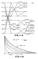
- Each table 1-6 is constructed using a different one of six probability distribution curves illustrated in Fig. 6. Each curve comprises an exponential function, with different curves having different mean values ranging from 1 to 32.
- the calculated predictive mean value PM K measures the steepness of the probability curve for a given quantized coefficient, and thus each Huffman code table is selected for a particular quantized coefficient by converting the value of PM K to the log (base 2) equivalent value, and using the converted value to specify the appropriate table.
- the table selected is ideally that table capable of encoding the quantized coefficient with the least number of bits.
- Coding of the transform coefficients proceeds as described until the predictive mean falls below a preselected fixed threshold, termed the run length.threshold.
- a run length code corresponding to the number of successive quantized coefficients having value zero is generated by coder unit 22 using table number 8 from appendix A. If the zero run extends to the end of the block, a special end of block code is generated by coder unit 22 from table number 8.
- the above described encoding process is graphically illustrated in Fig. 7 in which the trend of the predictive mean values is illustrated by the solid curve labelled PM i .
- the run length threshold is designated by the horizontal broken line, and the run length and end of block segments are designated with the legends RL and EOB, respectively.
- the numerical value of the run length threshold is one.
- Rate buffer 25 is a conventional unit capable of accepting binary input bits at a variable rate and generating bits at the output thereof at a constant rate of 2.39 x 10 5 bits/sec. in the preferred embodiment. Since the rate at which coder unit 22 ' supplies binary bits to the input of rate buffer 25 can vary widely, while the buffer output bit rate is constant, a rate feedback technique is incorporated into the encoder of F ig. 1 to minimize the probability of buffer overflow.
- a signal representative of the number of bits actually transferred from coder unit 22 to buffer unit 25 is coupled to distortion calculator unit 18 for each replenishment block K, and the value of the distortion constant D k ; which establishes-the magnitude of the minimum quantization interval for quantizer unit 23, is recalculated.
- the calculation is performed in accordance with the following relationship:
- the distortion calculator 18 updates the value of the block difference threshold T k for each encoded replenishment block in accordance with the following relationship:
- the quantizer unit 23 provides coarser quantization intervals for the encoding of the transform coefficients, which tends to reduce the number of bits per symbol generated by coder unit 22, and thus tends to reduce the buffer fullness.
- the block difference threshold Tk is raised, which tends to reduce the number of blocks selected for replenishment transformation, which also tends to reduce the buffer fullness.
- the distortion constant D k provides finer quantization intervals for processing the transform coefficients, which tends to increase the number of bits per symbol generated by coder unit 22; and the block difference threshold T k is lowered, tending to select more blocks for replenishment processing, both of which tend to increase the buffer fullness.
- Fig. 8 illustrates one entire frame of information.
- a frame of information commences with a frame sync code signal indicating the beginning of the frame, followed by a first control code signal B K which specifies the state of buffer fullness at the beginning of the frame.
- This control code signal is followed by the second control code signal D k , which is the actual value of the distortion constant at the beginning of the frame.
- this header information which is used to reset the decoder shown in Fig. 2 at the beginning of each frame, are groups of block symbols containing the block replenishment information. After the last such group, a new frame sync code signal indicates the beginning of the succeeding frame of information.
- Each group of block replenishment code symbols commences with the block address code, is followed by the two color quadrature component code symbols and continues with the coefficient code symbols, as indicated in Fig. 8.
- the arrangement of the coefficient codes indicated in Fig. 8 for the first block to be updated corresponds to the representative plot shown in Fig. 7.
- the block replenishment symbols encoded in the manner described above are transmitted over a suitable communication link to the decoder system shown in Fig. 2, which provides inverse processing for the received information code symbols.
- the initial value of the distortion constant D k is coupled to an inverse quantizer unit 23' and the first block of replenishment information is initially decoded in decoder unit-22'.
- Decoder unit 22' contains the inverse code tables illustrated in appendix B which generate digital values from the received code symbols applied to the input thereof.
- the tables are arranged in a manner similar to that employed in coder unit 22, so'that the block address codes, the color quadrature component codas and the DC coefficient code are all applied to their respective dedicated tables, while the cosine coefficient codes are applied on an individual basis to a selected one of six tables, depending on the value of the predictive mean calculated for each received quantized coefficient code.
- twelve-bit digital characters representing the quantized c o - efficients are inverse quantized in unit 23' by simply digitally multiplying each twelve-bit character with the value of D k , and the resulting inversely quantized cosine coefficients are stored in diagonal memory unit 21', along with the corresponding block address digital character, the digital character representing the DC term and the quadra- tur e chrominance characters.
- the coefficients are transformed to the time domain by subjecting the coefficients to a two-step inverse cosine transformation in unit 20', with the intermediate resulting values being stored back in diagonal memory unit 21'.
- the resulting pixel samples are stored in output memory unit 13, replacing the former eight by eight block of pixel information.
- the field of information stored in output memory unit 13' comprises a replica of the field of information stored in reference memory unit 14 of the Fig. 1 encoder.
- the replenished field information contained in output memory unit 13' is coupled to an output digital processor unit 12', and thence to analog processor unit 11' which converts the digital video data to analog form.
- the emerging analog video signals are coupled to a suitable utilization device, such as a raster scan monitor.
- a signal representing the number of bits transferred is coupled to distortion calculator unit 18', which updates the value of the distortion constant D k for each block of replenishment information.
- the distortion calculator 18' employs-the same algorithm as that noted above for distortion calculator 18.
- the luminance portion of a field of input video is sub- - sampled to provide 256 lines/frame and 256 samples/line (65,536 pixels/frame), as opposed to the normal standard of 512 lines/frame and 512 samples/line (262,144 pixels/frame).
- the full luminance field is recovered in output digital processor 12' by interpolative processing of the actual luminance samples transmitted through the system. Deleted luminance samples are reconstructed by summing adjacent samples and dividing the result by two. Thus, if A and B are adjacent luminance samples in a line, the intermediate sample is reconstructed by forming the sum + , and inserting this result between sample A and sample B.
- the quadrature chrominance components for each 8xE block of input video are compressed by first discarding the 2 least significant bits of each 8-bit digital chrominance quadrature component sample to form 6-bit digital characters.
- the separate quadrature component samples are averaged over the block by summing every other component sample in a given line, dividing the result by four, storing the result obtained for each line, summing the result for the eight lines in a block and dividing the result by eight.
- the initial sample array is:
- the first row average is:
- the first row average is:
- the block average is:
- the resulting block average for each component is stored as a 6-bit character in input memory 13.
- the full chrominance field is recovered in output digital processor 12' by inverse interpolative processing of the average chrominance samples transmitted through the system.
- the invention is especially adapted for use in a video teleconferencing system in which the prime criterion is bandwith reduction with minimum degradation in the subjective quality of the video images.
- the prime criterion is bandwith reduction with minimum degradation in the subjective quality of the video images.
- the required bit rate to reliably transmit video information without compression is 8.56 x 10 bits per second.
Abstract
Description
- This invention relates to information signal processing in general, and in particular to the field of processing time sequential information signals (such as video signals) for the purpose of compressing the amount of information to be transferred from an encoding site to a decoding site.
- In recent years, increasing efforts have been directed toward providing more efficient information signal encoding techniques used to process time sequential information signals prior to their transmission from a transmitting station to a receiving station. The requirement for more efficient encoding techniques has been prompted by two major factors: firstly, a substantial increase in the quantity of information required to be transferred via communication links and, secondly, maximum occupancy of the communication frequency bands available for voice and data transmission. An early technique employed to reduce the amount'of information required to be transferred without substantial degradation is the signal processing technique known as conditional replenishment, described in U.S. Patent No. 3,984,626 to Mounts et al., the disclosure of which is hereby incorporated by reference. Briefly, in the conditional replenishment signal processing technique, individual line element sample signals from a successive field of information are compared with the corresponding line elements in the previous field, and the difference therebetween is tested against a fixed threshold. If the difference exceeds the threshold value, the new value is encoded and transmitted to a receiving station, along with an appropriate address code specifying the line location of the sample to be updated in the field memory of the receiving station. Thus, rather than transmitting each and every line sample for every field, only those samples which differ by a significant threshold amount are transmitted, which substantially reduces the number of samples in the communication channel pipeline. Although this saving in the amount of actual data flowing through the communication pipeline is somewhat offset by the necessity of simultaneously transmitting the address information, this disadvantage is more than overcome by the substantial reduction in the total number of samples which must be transmitted in order to maintain the information current at the decoding site. When used to process video type information signals, an even greater reduction in the required number of transmitted samples is achieved due to the inherent nature of video signals, which possess intrinsic interfield correlation (e.g. abrupt interfield changes for background portions of video images occur relatively infrequently).
- Another compression technique known in the art is the use of transform domain encoding, in which each field of information signals is divided into a number of rectangular or square arrays of individual picture elements (for example a 16 pixel by 16 pixel array) termed blocks, and each block is converted to the transform domain. For each converted block, the individual transform coefficients are then encoded and transmitted along with appropriate address codes, as well as additional overhead information (e.g. field start signals, frame start signals and the like). One such transform domain processing system is disclosed in U.S. Patent No. 4,189,748 to Reis, the disclosure of which is hereby incorporated by reference.
- Although many types of mathematical transform functions have been proposed for implementation in a transform domain signal processing system, in reality most transform functions are inappropriate for implementation due to the complexity of the required logic circuitry. This disadvantage is exacerbated in applications requiring real time signal processing by virtue of the minimum time period required to perform the signal processing necessary to generate the values of the transform coefficients. For a general discussion of the advantages and disadvantages of the different types of transform functions, reference should be had to the collection of technical publications entitled "Image Transmission Techniques, Advances in Electronics and Electron Physics,
Supplement 12", Pratt, Academic Press, 1979, particularly the section entitled "Transform Image Coding". - . The invention comprises a method and system for processing time domain information signals which combines the advantages of conditional replenishment and transform domain coding in such a manner that information signal compression of a magnitude substantially greater than that available in known systems is achieved while affording real time information signal processing.
- In its broadest aspect, the invention provides a method of processing time domain information signals having a successive field format to effect substantial compression of the signals, the method including the steps of comparing corresponding blocks of time domain information signals from successive fields, converting a block of the time domain .information signals to a transform domain signal represented by discrete cosine transform coefficients when the difference between the corresponding blocks exceeds a first variable parametric value, and encoding the transform domain coefficients for subsequent utilization, e.g. transmission from a transmitting station to a receiving station, recording on video tape or other magnetic media, etc. The corresponding blocks of time domain information signals from successive fields are compared by storing the successive fields in memory on a pixel by pixel basis, retrieving the corresponding blocks from memory also on a pixel by pixel basis, forming the difference between corresponding pixels from the successive blocks, squaring the resulting difference signal, summing the squares of the resulting difference signals, and dividing the resulting sum by the number of pixels per block. In the preferred embodiment, the method is optimized by employing a total of 64 pixels per block arranged in an 8 by 8 array and by merging successive fields on a pixel by pixel basis, the merging being performed by summing corresponding pixels from successive fields in accordance with a predetermined weighting factor of 3/4 for the earlier appearing (previously merged) field and 1/4 for the later appearing field.
- The conversion of a block of the time domain information signals to the transform domain is accomplished by first transforming the individual block samples along a first direction, which is the horizontal line direction in the preferred embodiment, and subsequently transforming the same block samples along the orthogonal direction, which is the vertical direction in the preferred embodiment. For each transformed block, the individual block samples corresponding to the previous field are replaced with the updated block information, and the transformed coefficients for the converted block are stored in diagonal format in a diagonal memory unit. In addition, an address code indicating the field address of a transformed block is also stored in the diagonal memory for subsequent encoding.
- The transform coefficients for each converted block stored in the diagonal memony are encoded using a plurality of different code tables, one of the tables being dedicated to the first coefficient in each diagonal group, corresponding to the DC term and representing the average signal intensity of the converted block, and the remaining tables being selected on a coefficient by coefficient basis. Specifically, each transform coefficient (other than the first or DC coefficient) is first quantized by digitally dividing the coefficient by a variable parametric value Dy, after which the predictive mean value of each quantized coefficient'is calculated by summing a weighted portion of the actual value of that quantized coefficient with the predictive mean value of the previous quantized coefficient weighted by a different factor, and the newly calculated predictive mean value is used to select that one of the several available individual code tables capable of encoding the quantized coefficient value with a minimum number of binary bits. In addition to the tables noted above, separate tables are provided for encoding the block address of the encoded transform coefficients, for directly encoding the D.C. coefficient, and for run length coding certain coefficient values. In the case of time domain information signals comprising color video signals with quadrature components two preselected quantized coefficient code tables are used to represent the average value of each color quadrature component of the corresponding converted block.
- To further compress the amount of information encoded prior to utilization, those successive transform coefficients with zero value whose predictive mean lies below the value of a preselected fixed threshold are transmitted as a run length code. In addition, when the predictive values for successive remaining cosine coefficients in the converted block lie below the preselected fixed threshold, a single end-of-block code is generated.
- The codes corresponding to a given converted block are transferred at a variable rate to a rate buffer in the order of generation prior to utilization., and the number of binary bits transferred to the buffer is monitored in order to gauge the buffer fullness. The dynamic occupancy of the buffer is used to control the value of the variable parametric value DK in order to minimize the possibility of buffer overflow, utilizing a special algorithm. The buffer fullness state is also used to control the first variable parametric value -- termed the block difference threshold TK -- also by employing a special algorithm. Thus, as the rate buffer approaches the completely filled state, the magnitude of DK is increased, which increases the minimum quantizing interval employed in sampling the transform coefficients during the encoding process. In addition, the block difference threshold TK is similarly increased to reduce the number of blocks selected for conversion to the transform domain and subsequent encoding. Similarly, as the state of the buffer fullness decreases, both DK and TK are lowered in value in accordance with the special algorithms employed in order to increase the number of blocks selected for conversion to the transform domain and to decrease the minimum quantization interval used in the encoding process.
- The codes representing the converted blocks are formatted in the rate buffer in the following fashion. The start of each frame is denoted by a frame sync code signal, which is followed by a first control code signal representative of the buffer fullness at the beginning of the frame and a second control code signal representative of the quantizing interval DK value at the beginning of the same frame. The control code signals are followed by individual block replenishment code symbols which include a block address code specifying the field address of the corresponding block, the DC code term representative of the average intensity of the corresponding block, and the plurality of coefficient code terms representative of the predictive mean value of the transform coefficients for the corresponding block. For color video signal processing, the quadrature component code terms are included between the block address code and the DC code term. The termination of the last block is signified by the subsequent appearance of the frame sync code signal for the next succeeding frame.
- The decoding process is essentially the inverse of the encoding process. For each frame of encoded information, the first and second control code signals are used to establish the initial minimum quantization interval to be employed for inverse quantizing the block replenishment code symbols. The received replenishment code symbols are decoded using a parallel set of inverse code tables, which are selected using the same predictive mean algorithm as that employed in the encoding process. The block address, quadrature chrominance and D.C. term codes are coupled directly to a diagonal memory unit, while the coefficient code terms are inverse quantized by multiplying each code term by Dk, using the transmitted initial value of Dk for the first block of data, and the resulting coefficients are stored in the diagonal memory unit. After the first block has been decoded, the distortion constant Dk is recalculated and the newly calculated value of Dk is used to inverse quantize the next block of data.
- The coefficients stored in the diagonal memory unit are then transformed to time domain digital samples using an inverse discrete cosine transform, and the resulting samples are stored in an output memory unit, replacing previous samples representing the same block. The merged field samples 'stored in the output memory unit, which replicate the merged field samples stored in a corresponding reference memory unit at the encoder site, are finally processed to provide video output signals.
- Further compression is achieved according to the invention by special initial processing of the luminance and chrominance samples. The luminance signals are sub-sampled at less than the standard rate (which is 512 lines/frame and 512 samples/line for NTSC video), the preferred embodiment employing 256 lines/frame and 256 samples/line. Each quadrature chrominance component is sub-sampled at less 'than the standard"rate and averaged over a given block. In the preferred embodiment, each quadrature component is sub-sampled at one-half the standard rate for each block line and the sub-samples for each block line are averaged, after which each block line average is combined to obtain-a block average. Prior to averaging, each chrominance component sample is further modified by discarding the two least significant bits of the sample. After transmission from an encoding site to a decoding site, the full range of luminance and chrominance samples is recovered by individual interpolative processing of the received luminance and chrominance samples.
-
- Fig. 1 is a block diagram illustrating an encoder incorporating the invention;
- Fig. 2 is a block diagram illustrating a decoder incorporating the invention;
- Fig. 3 is a schematic view of a portion of a display screen illustrating the replenishment block size;
- Fig. 4 is a trellis diagram illustrating the cosine transform alogorithm employed in the preferred embodiment;
- Fig. 5 is a schematic diagram illustrating the manner in which transform coefficients are stored in a diagonal memory unit;
- Fig. 6 is set of probability distribution curves illustrating the manner in which the quantized coefficient encoding tables are constructed;
- Fig. 7 is a schematic diagram illustrating typical predictive mean values for a single block; and
- Fig. 8 is a schematic diagram illustrating the code formatting for one frame of replenishment information.
- Turning now to the drawings, Fig. 1 is a block diagram illustrating a preferred embodiment of the encoder portion of the invention. As seen in this Fig., analog video signals are coupled to the input of an analog processor unit 11 in which composite video input signals are separated into the standard luminance and quadrature chrominance components and converted to multi-bit digital samples at a predetermined sampling rate. In the preferred embodiment eight bit digital samples are taken at a 10.7 MHz sampling rate. The equivalent digital data samples produced in analog processor unit 11 are coupled to the input of an input
digital processor 12 in which incoming field samples are merged with the corresponding samples from the previous field in the manner described below. The resulting individual merged field samples from inputdigital processor 12 are stored in aninput memory unit 13 having a sufficient capacity to contain one field of digital information. An additional memory unit 14, termed a reference memory, is coupled to the data output ofinput memory unit 13. Reference memory unit.14 stores a reference field of information for comparison with a newly merged field stored ininput memory unit 13, and has the same capacity asinput memory unit 13. - In operation, the individual digital samples from an incoming field supplied to input
digital processor 12 are • added to the corresponding digital samples of the previously merged field stored ininput memory unit 13 on a weighted basis, and the resulting weighted sums are stored ininput memory unit 13, replacing the previously stored samples on a pixel by pixel basis. In the preferred embodiment, the samples are weighted by a facto=.of 3 to 1 between the older samples stored in theinput memory unit 13 and the incoming field samples, i.e. the earlier samples are multiplied by a factor of 3/4, the later samples are multiplied by the factor of 1/4 and the resulting weighted samples are added together. The weighting multiplication and the addition are accomplished with conventional digital multipliers and adders, in combination with appropriate conventional addressing logic. - Each newly merged field stored in
input memory unit 13 is compared on a block by block basis with the reference field stored in reference memory unit 14 by means of a block difference anddecision unit 16. As illustrated in Fig. 3, each block element consists of a rectangular array of 8 pixels by 8 pixels, and the difference between each block is obtained by digitally subtracting corresponding pixel samples read frominput memory unit 13 and reference memory unit 14 in block difference anddecision unit 16, squaring the resulting difference signals, summing the squares of the resulting difference signals, and dividing the resulting sum by the number of pixels per block (64). Each block difference value so obtained is tested against a threshold TK supplied from adistortion calculation unit 18. If the block difference exceeds the threshold, the corresponding block ininput memory unit 13 is converted to a set of transform coefficients by means of a one dimensioncosine transform unit 20, and the transform coefficients are stored in adiagonal memory unit 21 along with a corresponding block address code specifying the field block to which the transform coefficients correspond. In addition, whenever a block is selected for conversion to the transform domain, the reference memory unit 14 is updated by replacing the corresponding block in reference memory unit 14 with the newly selected block. - The conversion of each selected block to the transform domain is done by a one dimensional
cosine transform unit 20 in two steps: a first transformation along the horizontal direction, followed by a second transformation along the vertical direction. Thecosine transform unit 20 implements the well known discrete cosine transform function:

diagonal memory unit 21, and are subsequently recalled during the transformation in the vertical direction. After the selected block has been completely converted to-the transform domain, the resulting series of coefficients is stored indiagonal memory unit 21 along with a multi-bit digital word specifying the block address of the block corresponding to the series of coefficients and two multi-bit digital words specifying the average value of the chrominance quadrature components for the corresponding block, the coefficients being arranged in the diagonal form illustrated schematically in Fig. 5. - The transform coefficients and corresponding block address and chrominance quadrature digital characters are next encoded for subsequent transmission in the following manner. The block address digital character corresponding to a series of transform coefficients is coupled directly to a
coder unit 22 which contains in the preferred embodiment nine separate code tables, eight tables containing a set of code characters arranged according to the Huffman code technique, in which the number of bits per specific character depends upon the probability of occurrence of that character, and one table containing a set of code characters arranged according to a special variable length coding technique specified below. The special variable length code table is dedicated for use with the block address code, and the application of a new block address code to the dedicated code table results in the generation of a block address transmission code. The block address is actually encoded by forming the numerical difference between the current block address and the address of the most recent previously encoded block address, and generating a code in accordance with the following algorithm: - If

- If

- If

- Ak = numerical address of current block
- Ak-1 = numerical address of most recently encoded block.
- The color quadrature components are encoded using dedicated Huffman code tables in
coder unit 22. The tables listed astable number 2 andtable number 3 in appendix A are used for the Q and I component values, respectively. After the block address and the co.lor quadrature components have been encoded in the manner noted above, the first coefficient indiagonal memory unit 21 corresponding to the block, and which represents the average luminance of the block, is encoded using dedicated Huffmancode table number 7 shown in appendix A. Thereafter, the cosine coefficients are processed for encoding by passing each cosine coefficient through aquantizer unit 23 in which the individual coefficients are divided by a distortion constant Dk supplied bydistortion calculator unit 18. More particularly, each coefficient is multiplied by thequantity 1/Dk using a digital multiplier, and the resulting rounded product, designated as a quantized cosine coefficient, is coupled tocoder unit 22. In the preferred embodiment, each quantized cosine coefficient comprises a 12 bit digital character having 1 sign bit and 11 bits of magnitude. For each quantized cosine coefficient received incoder unit 22, the predictive mean value is calculated using the. following relationship:
- The four most significant magnitude bits of each quantized coefficient are next examined in
coder unit 22 using conventional logic circuitry and, if the most significant four bits are zero, the quantized coefficient-is Huffman coded using one of tables 1-6 listed in appendix A. Each table 1-6 is constructed using a different one of six probability distribution curves illustrated in Fig. 6. Each curve comprises an exponential function, with different curves having different mean values ranging from 1 to 32. The calculated predictive mean value PMK measures the steepness of the probability curve for a given quantized coefficient, and thus each Huffman code table is selected for a particular quantized coefficient by converting the value of PMK to the log (base 2) equivalent value, and using the converted value to specify the appropriate table. The table selected is ideally that table capable of encoding the quantized coefficient with the least number of bits. - When the four most significant bits of a quantized coefficient are non-zero, a Huffman coded special escape symbol from the appropriate table and the actual twelve-bit quantized coefficient are transmitted. The escape symbol is the last symbol found in the Appendix A tables.
- Coding of the transform coefficients proceeds as described until the predictive mean falls below a preselected fixed threshold, termed the run length.threshold. When this occurs, a run length code corresponding to the number of successive quantized coefficients having value zero is generated by
coder unit 22 usingtable number 8 from appendix A. If the zero run extends to the end of the block, a special end of block code is generated bycoder unit 22 fromtable number 8. The above described encoding process is graphically illustrated in Fig. 7 in which the trend of the predictive mean values is illustrated by the solid curve labelled PMi. The run length threshold is designated by the horizontal broken line, and the run length and end of block segments are designated with the legends RL and EOB, respectively. In the preferred embodiment, the numerical value of the run length threshold is one. - The code characters generated in
coder unit 22 are stored in their order of generation in arate buffer unit 25 having a predetermined maximum capacityN. Rate buffer 25 is a conventional unit capable of accepting binary input bits at a variable rate and generating bits at the output thereof at a constant rate of 2.39 x 105 bits/sec. in the preferred embodiment. Since the rate at which coder unit 22 'supplies binary bits to the input ofrate buffer 25 can vary widely, while the buffer output bit rate is constant, a rate feedback technique is incorporated into the encoder of Fig. 1 to minimize the probability of buffer overflow. For this purpose, a signal representative of the number of bits actually transferred fromcoder unit 22 to bufferunit 25 is coupled todistortion calculator unit 18 for each replenishment block K, and the value of the distortion constant Dk; which establishes-the magnitude of the minimum quantization interval forquantizer unit 23, is recalculated. The calculation is performed in accordance with the following relationship: -


- DK = Distortion parameter for block K
- D'K = Filtered distortion parameter

- T = a constant (close to 1)
- KD = a constant
- BK = # of bits in buffer for block K
- N = Max. number of bits
- In addition, the
distortion calculator 18 updates the value of the block difference threshold Tk for each encoded replenishment block in accordance with the following relationship: -


- TK = replenishment threshold for block K
- TINIT = initial threshold (about 5 for 8-bit input data)
- KR = multiplier constant (about 25-75)
- BLOW = low cutoff (about .1 of buffer)
- BHIGH = high cutoff (about .75 of buffer)
- Thus, as the
buffer unit 25 fullness increases, thequantizer unit 23 provides coarser quantization intervals for the encoding of the transform coefficients, which tends to reduce the number of bits per symbol generated bycoder unit 22, and thus tends to reduce the buffer fullness. In addition, the block difference threshold Tk is raised, which tends to reduce the number of blocks selected for replenishment transformation, which also tends to reduce the buffer fullness. Similarly, when the buffer fullness decreases, the distortion constant Dk provides finer quantization intervals for processing the transform coefficients, which tends to increase the number of bits per symbol generated bycoder unit 22; and the block difference threshold Tk is lowered, tending to select more blocks for replenishment processing, both of which tend to increase the buffer fullness. - The manner in which the serially generated code symbols representing the block replenishment information are arranged for transmission from
buffer unit 25 to a decoder site is shown in Fig. 8, which illustrates one entire frame of information. As seen in this Fig., a frame of information commences with a frame sync code signal indicating the beginning of the frame, followed by a first control code signal BK which specifies the state of buffer fullness at the beginning of the frame. This control code signal is followed by the second control code signal Dk, which is the actual value of the distortion constant at the beginning of the frame. Following this header information, which is used to reset the decoder shown in Fig. 2 at the beginning of each frame, are groups of block symbols containing the block replenishment information. After the last such group, a new frame sync code signal indicates the beginning of the succeeding frame of information. - Each group of block replenishment code symbols commences with the block address code, is followed by the two color quadrature component code symbols and continues with the coefficient code symbols, as indicated in Fig. 8. The arrangement of the coefficient codes indicated in Fig. 8 for the first block to be updated corresponds to the representative plot shown in Fig. 7.
- The block replenishment symbols encoded in the manner described above are transmitted over a suitable communication link to the decoder system shown in Fig. 2, which provides inverse processing for the received information code symbols. Thus, after receipt of a frame sync code signal, the initial value of the distortion constant Dk is coupled to an inverse quantizer unit 23' and the first block of replenishment information is initially decoded in decoder unit-22'. Decoder unit 22' contains the inverse code tables illustrated in appendix B which generate digital values from the received code symbols applied to the input thereof. The tables are arranged in a manner similar to that employed in
coder unit 22, so'that the block address codes, the color quadrature component codas and the DC coefficient code are all applied to their respective dedicated tables, while the cosine coefficient codes are applied on an individual basis to a selected one of six tables, depending on the value of the predictive mean calculated for each received quantized coefficient code. The emerging . twelve-bit digital characters representing the quantized co- efficients are inverse quantized in unit 23' by simply digitally multiplying each twelve-bit character with the value of Dk, and the resulting inversely quantized cosine coefficients are stored in diagonal memory unit 21', along with the corresponding block address digital character, the digital character representing the DC term and the quadra- ture chrominance characters. The coefficients are transformed to the time domain by subjecting the coefficients to a two-step inverse cosine transformation in unit 20', with the intermediate resulting values being stored back in diagonal memory unit 21'. After the inverse cosine transformation process has been completed, the resulting pixel samples are stored inoutput memory unit 13, replacing the former eight by eight block of pixel information. It should be noted that the field of information stored in output memory unit 13' comprises a replica of the field of information stored in reference memory unit 14 of the Fig. 1 encoder. - The replenished field information contained in output memory unit 13' is coupled to an output digital processor unit 12', and thence to analog processor unit 11' which converts the digital video data to analog form. The emerging analog video signals are coupled to a suitable utilization device, such as a raster scan monitor.
- As binary bits are transferred from buffer unit 25' to decoder unit 22', a signal representing the number of bits transferred is coupled to distortion calculator unit 18', which updates the value of the distortion constant Dk for each block of replenishment information. The distortion calculator 18' employs-the same algorithm as that noted above for
distortion calculator 18. - Further compression of the input video is obtained by two additional signal processing techniques. Firstly, the luminance portion of a field of input video is sub- - sampled to provide 256 lines/frame and 256 samples/line (65,536 pixels/frame), as opposed to the normal standard of 512 lines/frame and 512 samples/line (262,144 pixels/frame). After. decoding, the full luminance field is recovered in output digital processor 12' by interpolative processing of the actual luminance samples transmitted through the system. Deleted luminance samples are reconstructed by summing adjacent samples and dividing the result by two. Thus, if A and B are adjacent luminance samples in a line, the intermediate sample is reconstructed by forming the sum


- The quadrature chrominance components for each 8xE block of input video are compressed by first discarding the 2 least significant bits of each 8-bit digital chrominance quadrature component sample to form 6-bit digital characters. For each 8x8 block, the separate quadrature component samples are averaged over the block by summing every other component sample in a given line, dividing the result by four, storing the result obtained for each line, summing the result for the eight lines in a block and dividing the result by eight. Specifically, for the I quadrature component for block K, the initial sample array is:

- The first row average is:

- The last row average is:

- 'The block average is:

- For the Q quadrature component, the first row average is:

- The last row average is:

- The block average is:

- The resulting block average for each component is stored as a 6-bit character in
input memory 13. The full chrominance field is recovered in output digital processor 12' by inverse interpolative processing of the average chrominance samples transmitted through the system. - While suitable for many applications requiring information signal compression, the invention is especially adapted for use in a video teleconferencing system in which the prime criterion is bandwith reduction with minimum degradation in the subjective quality of the video images. At a typical sampling rate of 10.7 MHz for digital video transmission using eight-bits per digital sample character, the required bit rate to reliably transmit video information without compression is 8.56 x 10 bits per second. By processing video signals according to the invention, using the same sample rate and the same size digital characters (i.e. eight-bits) in the analog to digital converter'section of the encoder, and the digital to analog section of the decoder, compressed digital video can be transmitted from the
encoder buffer unit 25 to the decoder buffer unit 25' at a rate of 2.39 x 105 bits per second, which is .25 percent of the standard uncompressed digital bit rate. As will be appreciated by those skilled in the art, such a substantial reduction in the bit rate enables video information of good 'picture quality to be transmitted over a communication link having a substantially narrower bandwith, for example four conventional digital voice channels, with the result that substantially more information traffic can be routed over available communication links. - While the above provides a full and complete disclosure of the preferred embodiments of the invention, various modifications, alternate constructions and equivalents may be employed without departing from the true spirit and scope of the invention. For example, while eight by eight pixel blocks are employed in the preferred embodiment of the invention, blocks of other sizes may be employed, if desired. The relevant criteria for selecting appropriate block sizes are the processing time required by the block difference and
decision unit 16, thecosine transform unit 20, thequantizer unit 23, thecoder unit 22 and thedistortion calculator 18. In general, larger blocks require more processing time, and the speed of currently available digital circuitry provides a practical limitation of about 32 pixels by 32 pixels on the maximum block size. In addition, for applications in which the amount of interframe image motion is excessive (i.e. greater than that normally present in video conferencing applications), a smaller block size may be necessary in order to provide decoded video signals of good subjective quality. Selection of smaller block sizes, however, increases the required minimum bit rate for thebuffer units 25, 25'. In addition, different weighting factors may be employed for field merging, if desired? however, in the development of the preferred embodiment it has been discovered that a ratio of seven to one results in decoded video signals which are quite blurry, while-a ratio approaching one to one results in a substantially increased number of blocks selected for replenishment, requiring a higher minimum bit rate for reliable transmission and decoding. The above description and illustrations, therefore, should not be construed as limiting the scope of the invention, which is defined by the appended claims.


Claims (12)


Applications Claiming Priority (2)
| Application Number | Priority Date | Filing Date | Title |
|---|---|---|---|
| US06/336,984 US4541012A (en) | 1982-01-04 | 1982-01-04 | Video bandwidth reduction system employing interframe block differencing and transform domain coding |
| US336984 | 1989-04-12 |
Publications (3)
| Publication Number | Publication Date |
|---|---|
| EP0084270A2 true EP0084270A2 (en) | 1983-07-27 |
| EP0084270A3 EP0084270A3 (en) | 1983-08-31 |
| EP0084270B1 EP0084270B1 (en) | 1986-06-04 |
Family
ID=23318588
Family Applications (1)
| Application Number | Title | Priority Date | Filing Date |
|---|---|---|---|
| EP82307026A Expired EP0084270B1 (en) | 1982-01-04 | 1982-12-31 | Video bandwidth reduction system employing interframe block differencing and transform domain coding |
Country Status (4)
| Country | Link |
|---|---|
| US (1) | US4541012A (en) |
| EP (1) | EP0084270B1 (en) |
| CA (1) | CA1209266A (en) |
| DE (1) | DE3271602D1 (en) |
Cited By (16)
| Publication number | Priority date | Publication date | Assignee | Title |
|---|---|---|---|---|
| EP0123456A2 (en) * | 1983-03-28 | 1984-10-31 | Compression Labs, Inc. | A combined intraframe and interframe transform coding method |
| FR2575351A1 (en) * | 1984-12-21 | 1986-06-27 | Thomson Csf | ADAPTIVE METHOD FOR ENCODING AND DECODING A TRANSFORMATION IMAGE SUITE, AND DEVICES FOR IMPLEMENTING SAID METHOD |
| EP0201679A1 (en) * | 1985-04-17 | 1986-11-20 | Siemens Aktiengesellschaft | Method for reducing the image data of digital television signals |
| US4694336A (en) * | 1985-04-12 | 1987-09-15 | Telefunken Fernseh Und Rundfunk Gmbh | Digital data transmission method |
| EP0323363A1 (en) * | 1987-12-30 | 1989-07-05 | Thomson Grand Public | Method of synchronizing, for transmission, on an asynchronous channel, a sequence of pictures coded with a variable-length code, and device for carrying out this method |
| EP0323362A1 (en) * | 1987-12-30 | 1989-07-05 | Thomson Grand Public | Adaptive method of transform coding and decoding a sequence of pictures, and devices for carrying out this method |
| FR2640840A1 (en) * | 1988-12-16 | 1990-06-22 | Thomson Csf | Process for coding an image string, by a transformation and a plurality of variable-length codes, and devices for implementing this process |
| EP0406508A1 (en) * | 1989-07-04 | 1991-01-09 | Rai Radiotelevisione Italiana | Device for reducing the redundancy in blocks of digital video data in DCT encoding |
| US4995071A (en) * | 1988-07-08 | 1991-02-19 | Telenorma Telefonbau Und Normalzeit Gmbh | Video conference installation |
| EP0445727A2 (en) * | 1990-03-05 | 1991-09-11 | Mitsubishi Denki Kabushiki Kaisha | Variable length coding method |
| WO1992003019A1 (en) * | 1990-07-30 | 1992-02-20 | Mpr Teltech Ltd. | Method and apparatus for image data processing |
| EP0498656A1 (en) * | 1991-02-08 | 1992-08-12 | Sony Corporation | Encoding video signals |
| EP0588653A2 (en) * | 1992-09-16 | 1994-03-23 | Fujitsu Limited | Image data coding and restoring method and appatatus for coding and restoring the same |
| US5453786A (en) * | 1990-07-30 | 1995-09-26 | Mpr Teltech Ltd. | Method and apparatus for image data processing |
| US6563875B2 (en) | 1987-12-30 | 2003-05-13 | Thomson Licensing S.A. | Adaptive method of encoding and decoding a series of pictures by transformation, and devices for implementing this method |
| EP1455516A2 (en) * | 1996-10-31 | 2004-09-08 | Sensormatic Electronics Corporation | Intelligent video information management system |
Families Citing this family (86)
| Publication number | Priority date | Publication date | Assignee | Title |
|---|---|---|---|---|
| US4661862A (en) * | 1984-04-27 | 1987-04-28 | Rca Corporation | Differential PCM video transmission system employing horizontally offset five pixel groups and delta signals having plural non-linear encoding functions |
| US4910609A (en) * | 1984-06-07 | 1990-03-20 | Raytel Systems Corporation | Teleradiology system |
| US4860112A (en) * | 1984-06-07 | 1989-08-22 | Raytel Systems Corporation | Teleradiology system having multiple compressor/expanders |
| US4748511A (en) * | 1984-06-07 | 1988-05-31 | Raytel Systems Corporation | Teleradiology system |
| EP0216928B1 (en) * | 1984-12-06 | 1993-03-03 | Dainippon Screen Mfg. Co., Ltd. | Method and apparatus for compressing image data |
| US4956808A (en) * | 1985-01-07 | 1990-09-11 | International Business Machines Corporation | Real time data transformation and transmission overlapping device |
| US4751742A (en) * | 1985-05-07 | 1988-06-14 | Avelex | Priority coding of transform coefficients |
| DE3684047D1 (en) * | 1985-07-02 | 1992-04-09 | Matsushita Electric Ind Co Ltd | BLOCK CODING DEVICE. |
| FR2589020B1 (en) * | 1985-10-22 | 1987-11-20 | Eude Gerard | TRANSFORMATION HYBRID CODING METHOD FOR TRANSMITTING IMAGE SIGNALS |
| JP2612557B2 (en) * | 1985-12-18 | 1997-05-21 | ソニー株式会社 | Data transmission receiving system and data decoding device |
| DE3605032A1 (en) * | 1986-02-18 | 1987-08-20 | Thomson Brandt Gmbh | DIGITAL MESSAGE TRANSMISSION METHOD |
| US5007102A (en) * | 1986-03-20 | 1991-04-09 | At&T Bell Laboratories | Data compression using block list transform |
| JPS62230281A (en) * | 1986-03-31 | 1987-10-08 | Toshiba Corp | Picture transmission system |
| IT1190565B (en) * | 1986-04-07 | 1988-02-16 | Cselt Centro Studi Lab Telecom | PROCEDURE AND CODING DEVICE FOR NUMBERED SIGNALS BY VECTOR QUANTIZATION |
| JP2608400B2 (en) * | 1986-06-16 | 1997-05-07 | 富士写真フイルム株式会社 | Image reconstruction method from compressed image data |
| DE3626916A1 (en) * | 1986-08-08 | 1988-02-11 | Thomson Brandt Gmbh | METHOD FOR TRANSMITTING A VIDEO SIGNAL |
| US4691233A (en) * | 1986-09-30 | 1987-09-01 | Rca Corporation | Rate buffer control of difference signal decimation and interpolation for adaptive differential pulse code modulator |
| US4700226A (en) * | 1986-10-17 | 1987-10-13 | Rca Corporation | Rate buffer control of predicted signal decimation and interpolation for adaptive differential pulse code modulator |
| US4851906A (en) * | 1986-11-04 | 1989-07-25 | Nec Corporation | Data compression using orthogonal transform and vector quantization |
| US4706260A (en) * | 1986-11-07 | 1987-11-10 | Rca Corporation | DPCM system with rate-of-fill control of buffer occupancy |
| US4816914A (en) * | 1987-01-07 | 1989-03-28 | Pictel Corporation | Method and apparatus for efficiently encoding and decoding image sequences |
| US4833535A (en) * | 1987-02-04 | 1989-05-23 | Kabushiki Kaisha Toshiba | Image transmission apparatus |
| SE454734B (en) * | 1987-02-20 | 1988-05-24 | Harald Brusewitz | PROCEDURE AND DEVICE FOR TRANSMISSION AND RECEPTION AT VARIABLE LENGTH CODING |
| JP2527351B2 (en) * | 1987-02-25 | 1996-08-21 | 富士写真フイルム株式会社 | Image data compression method |
| JP2532909B2 (en) * | 1987-02-25 | 1996-09-11 | 富士写真フイルム株式会社 | Image data compression device by vector quantization |
| EP0280313B1 (en) * | 1987-02-25 | 1994-05-18 | Fuji Photo Film Co., Ltd. | Method of compressing image signals by vector quantization |
| US4791598A (en) * | 1987-03-24 | 1988-12-13 | Bell Communications Research, Inc. | Two-dimensional discrete cosine transform processor |
| JP2604371B2 (en) * | 1987-04-30 | 1997-04-30 | 日本電気株式会社 | Orthogonal transform coding device |
| US4849810A (en) * | 1987-06-02 | 1989-07-18 | Picturetel Corporation | Hierarchial encoding method and apparatus for efficiently communicating image sequences |
| US4780761A (en) * | 1987-06-02 | 1988-10-25 | Eastman Kodak Company | Digital image compression and transmission system visually weighted transform coefficients |
| US4772956A (en) * | 1987-06-02 | 1988-09-20 | Eastman Kodak Company | Dual block still video compander processor |
| US4764805A (en) * | 1987-06-02 | 1988-08-16 | Eastman Kodak Company | Image transmission system with line averaging preview mode using two-pass block-edge interpolation |
| US4774587A (en) * | 1987-06-02 | 1988-09-27 | Eastman Kodak Company | Still video transceiver processor |
| BE1000643A5 (en) * | 1987-06-05 | 1989-02-28 | Belge Etat | METHOD FOR CODING IMAGE SIGNALS. |
| FR2621194B1 (en) * | 1987-09-29 | 1989-12-29 | Labo Electronique Physique | DEVICE FOR CODING DIGITAL VIDEO SIGNALS |
| US4868653A (en) * | 1987-10-05 | 1989-09-19 | Intel Corporation | Adaptive digital video compression system |
| US4918523A (en) * | 1987-10-05 | 1990-04-17 | Intel Corporation | Digital video formatting and transmission system and method |
| US5028995A (en) * | 1987-10-28 | 1991-07-02 | Hitachi, Ltd. | Picture signal processor, picture signal coder and picture signal interpolator |
| EP0314018B1 (en) * | 1987-10-30 | 1993-09-01 | Nippon Telegraph And Telephone Corporation | Method and apparatus for multiplexed vector quantization |
| US4897855A (en) * | 1987-12-01 | 1990-01-30 | General Electric Company | DPCM system with adaptive quantizer having unchanging bin number ensemble |
| US4897717A (en) * | 1988-03-30 | 1990-01-30 | Starsignal, Inc. | Computer-based video compression system |
| US4847677A (en) * | 1988-04-27 | 1989-07-11 | Universal Video Communications Corp. | Video telecommunication system and method for compressing and decompressing digital color video data |
| US4914508A (en) * | 1988-04-27 | 1990-04-03 | Universal Video Communications Corp. | Method and system for compressing and statistically encoding color video data |
| US4843466A (en) * | 1988-04-27 | 1989-06-27 | Universal Video Communications Corp. | Method and system for decompressing color video slope encoded data |
| US4849807A (en) * | 1988-04-27 | 1989-07-18 | Universal Video Communications Corp. | Method and system for compressing color video feature encoded data |
| US4816901A (en) * | 1988-04-27 | 1989-03-28 | Universal Video Communications Corp. | Method and system for compressing color video data |
| US4857993A (en) * | 1988-04-27 | 1989-08-15 | Universal Video Communications Corp. | Method and system for decompressing digital color video statistically encoded data |
| US4857991A (en) * | 1988-04-27 | 1989-08-15 | Universal Video Communications Corp. | Method and system for decompressing color video feature encoded data |
| US4984076A (en) * | 1988-07-27 | 1991-01-08 | Kabushiki Kaisha Toshiba | Image compression coding system |
| US4979039A (en) * | 1989-01-30 | 1990-12-18 | Information Technologies Research Inc. | Method and apparatus for vector quantization by hashing |
| US5067152A (en) * | 1989-01-30 | 1991-11-19 | Information Technologies Research, Inc. | Method and apparatus for vector quantization |
| DE3943880B4 (en) * | 1989-04-17 | 2008-07-17 | Fraunhofer-Gesellschaft zur Förderung der angewandten Forschung e.V. | Digital coding method |
| DE3914267A1 (en) * | 1989-04-29 | 1990-10-31 | Thomson Brandt Gmbh | SIGNAL PROCESSING SYSTEM FOR DIGITAL SIGNALS |
| US5142380A (en) * | 1989-10-23 | 1992-08-25 | Ricoh Company, Ltd. | Image data processing apparatus |
| JPH03214868A (en) * | 1990-01-19 | 1991-09-20 | Ricoh Co Ltd | Automatic focusing device |
| US5128754A (en) * | 1990-03-30 | 1992-07-07 | New York Institute Of Technology | Apparatus and method for encoding and decoding video |
| US5146324A (en) * | 1990-07-31 | 1992-09-08 | Ampex Corporation | Data compression using a feedforward quantization estimator |
| US5049992A (en) * | 1990-08-27 | 1991-09-17 | Zenith Electronics Corporation | HDTV system with receivers operable at different levels of resolution |
| GB9022326D0 (en) * | 1990-10-15 | 1990-11-28 | British Telecomm | Signal coding |
| JPH04157889A (en) * | 1990-10-20 | 1992-05-29 | Fujitsu Ltd | Automatic adjusting method for person image pickup position |
| US5303058A (en) * | 1990-10-22 | 1994-04-12 | Fujitsu Limited | Data processing apparatus for compressing and reconstructing image data |
| SG95586A1 (en) * | 1991-02-07 | 2003-04-23 | Canon Kk | Image encoding apparatus |
| TW223690B (en) * | 1991-02-13 | 1994-05-11 | Ampex | |
| US5457780A (en) * | 1991-04-17 | 1995-10-10 | Shaw; Venson M. | System for producing a video-instruction set utilizing a real-time frame differential bit map and microblock subimages |
| JPH0563996A (en) * | 1991-09-02 | 1993-03-12 | Ricoh Co Ltd | Image processor |
| WO1994009595A1 (en) * | 1991-09-20 | 1994-04-28 | Shaw Venson M | Method and apparatus including system architecture for multimedia communications |
| US6424989B1 (en) * | 1991-09-20 | 2002-07-23 | Venson M. Shaw | Object-oriented transaction computing system |
| US5434623A (en) * | 1991-12-20 | 1995-07-18 | Ampex Corporation | Method and apparatus for image data compression using combined luminance/chrominance coding |
| US5339108A (en) * | 1992-04-09 | 1994-08-16 | Ampex Corporation | Ordering and formatting coded image data and reconstructing partial images from the data |
| US5389965A (en) * | 1993-04-01 | 1995-02-14 | At&T Corp. | Video telephone station having variable image clarity |
| JP3125543B2 (en) * | 1993-11-29 | 2001-01-22 | ソニー株式会社 | Signal encoding method and apparatus, signal decoding method and apparatus, and recording medium |
| US5850260A (en) * | 1995-03-08 | 1998-12-15 | Lucent Technologies Inc. | Methods and apparatus for determining a coding rate to transmit a set of symbols |
| US5872599A (en) * | 1995-03-08 | 1999-02-16 | Lucent Technologies Inc. | Method and apparatus for selectively discarding data when required in order to achieve a desired Huffman coding rate |
| DE19524872C1 (en) * | 1995-07-07 | 1997-02-20 | Siemens Ag | Method and arrangement for coding and decoding a video data stream for all picture elements of the video data stream |
| US6101276A (en) | 1996-06-21 | 2000-08-08 | Compaq Computer Corporation | Method and apparatus for performing two pass quality video compression through pipelining and buffer management |
| US6256350B1 (en) * | 1998-03-13 | 2001-07-03 | Conexant Systems, Inc. | Method and apparatus for low cost line-based video compression of digital video stream data |
| US6385248B1 (en) * | 1998-05-12 | 2002-05-07 | Hitachi America Ltd. | Methods and apparatus for processing luminance and chrominance image data |
| US7079697B2 (en) * | 2001-03-19 | 2006-07-18 | Texas Instruments Incorporated | Image compression with transform coefficient analysis |
| JP4130780B2 (en) | 2002-04-15 | 2008-08-06 | 松下電器産業株式会社 | Image encoding method and image decoding method |
| JP4368575B2 (en) * | 2002-04-19 | 2009-11-18 | パナソニック株式会社 | Variable length decoding method, variable length decoding apparatus and program |
| US7551785B2 (en) * | 2003-07-03 | 2009-06-23 | Canadian Space Agency | Method and system for compressing a continuous data flow in real-time using cluster successive approximation multi-stage vector quantization (SAMVQ) |
| US8195481B2 (en) | 2005-02-25 | 2012-06-05 | Virtual Radiologic Corporaton | Teleradiology image processing system |
| US8229761B2 (en) | 2005-02-25 | 2012-07-24 | Virtual Radiologic Corporation | Enhanced multiple resource planning and forecasting |
| US8145503B2 (en) | 2005-02-25 | 2012-03-27 | Virtual Radiologic Corporation | Medical image metadata processing |
| US7729928B2 (en) * | 2005-02-25 | 2010-06-01 | Virtual Radiologic Corporation | Multiple resource planning system |
| US9648355B2 (en) * | 2014-03-07 | 2017-05-09 | Eagle Eye Networks, Inc. | Adaptive security camera image compression apparatus and method of operation |
Citations (3)
| Publication number | Priority date | Publication date | Assignee | Title |
|---|---|---|---|---|
| DE2336857A1 (en) * | 1972-07-19 | 1974-01-31 | Fujitsu Ltd | IMAGE TRANSFER SYSTEM |
| US4245248A (en) * | 1979-04-04 | 1981-01-13 | Bell Telephone Laboratories, Incorporated | Motion estimation and encoding of video signals in the transform domain |
| DE3029190A1 (en) * | 1980-08-01 | 1982-03-18 | Licentia Patent-Verwaltungs-Gmbh, 6000 Frankfurt | Differential PCM system for TV line reduction code - uses transform coding and spectral coefficient prediction to reduce TV transmitted line code |
Family Cites Families (9)
| Publication number | Priority date | Publication date | Assignee | Title |
|---|---|---|---|---|
| US3366739A (en) * | 1964-09-30 | 1968-01-30 | North American Rockwell | Bandwidth reduction system for reconstituting non-transmitted signals from transmitted signals |
| US4224678A (en) * | 1976-04-05 | 1980-09-23 | Northrop Corporation | Method and apparatus for implementing a processor based on the rationalized Haar transform for the purpose of real time compression of video data |
| JPS5382219A (en) * | 1976-12-28 | 1978-07-20 | Nec Corp | Television signal coding unit |
| DE2706080C2 (en) * | 1977-02-12 | 1986-10-23 | Philips Patentverwaltung Gmbh, 2000 Hamburg | Method for adaptive quantization of transformation coefficients of an image and arrangement for carrying out the method |
| FR2412987A1 (en) * | 1977-12-23 | 1979-07-20 | Ibm France | PROCESS FOR COMPRESSION OF DATA RELATING TO THE VOICE SIGNAL AND DEVICE IMPLEMENTING THIS PROCEDURE |
| US4179709A (en) * | 1978-01-10 | 1979-12-18 | Bell & Howell Company | Video information bandwidth compression |
| JPS5516503A (en) * | 1978-07-20 | 1980-02-05 | Ricoh Co Ltd | Facsimile system |
| US4254438A (en) * | 1978-12-13 | 1981-03-03 | Kokusai Denshin Denwa Kabushiki Kaisha | Coding method for facsimile signal |
| US4302775A (en) * | 1978-12-15 | 1981-11-24 | Compression Labs, Inc. | Digital video compression system and methods utilizing scene adaptive coding with rate buffer feedback |
-
1982
- 1982-01-04 US US06/336,984 patent/US4541012A/en not_active Expired - Lifetime
- 1982-12-22 CA CA000418399A patent/CA1209266A/en not_active Expired
- 1982-12-31 DE DE8282307026T patent/DE3271602D1/en not_active Expired
- 1982-12-31 EP EP82307026A patent/EP0084270B1/en not_active Expired
Patent Citations (3)
| Publication number | Priority date | Publication date | Assignee | Title |
|---|---|---|---|---|
| DE2336857A1 (en) * | 1972-07-19 | 1974-01-31 | Fujitsu Ltd | IMAGE TRANSFER SYSTEM |
| US4245248A (en) * | 1979-04-04 | 1981-01-13 | Bell Telephone Laboratories, Incorporated | Motion estimation and encoding of video signals in the transform domain |
| DE3029190A1 (en) * | 1980-08-01 | 1982-03-18 | Licentia Patent-Verwaltungs-Gmbh, 6000 Frankfurt | Differential PCM system for TV line reduction code - uses transform coding and spectral coefficient prediction to reduce TV transmitted line code |
Non-Patent Citations (2)
| Title |
|---|
| IEEE TRANSACTIONS ON COMMUNICATIONS, vol. COM-25, no. 11, November 1977, New York ALI HABIBI "Survey of Adaptive Image Coding Techniques pages 1275-1284 * Page 1278, column 2, paragraph 2, lines 1-8 ; page 1279, column 1, paragraph1 * * |
| IEEE TRANSACTIONS ON COMMUNICATIONS, vol. COM-25, no. 11, November 1977, New York WEN-HSIUNG CHEN et al. "Adaptive Coding of Monochrome and Color Images" pages 1285-1292 * Page 1285, column 1 - column 2, paragraph 2 ; page 1287, column 1, lines 9-11 ; page 1288, fig. 6, column 2, lines 1,2 ; page 1289, column 2, paragraph1 * * |
Cited By (39)
| Publication number | Priority date | Publication date | Assignee | Title |
|---|---|---|---|---|
| EP0123456A2 (en) * | 1983-03-28 | 1984-10-31 | Compression Labs, Inc. | A combined intraframe and interframe transform coding method |
| EP0123456A3 (en) * | 1983-03-28 | 1986-12-30 | Compression Labs, Inc. | A combined intraframe and interframe transform coding system |
| FR2575351A1 (en) * | 1984-12-21 | 1986-06-27 | Thomson Csf | ADAPTIVE METHOD FOR ENCODING AND DECODING A TRANSFORMATION IMAGE SUITE, AND DEVICES FOR IMPLEMENTING SAID METHOD |
| EP0189703A1 (en) * | 1984-12-21 | 1986-08-06 | Thomson Grand Public | Method for the adaptive transform coding and decoding of a picture sequence, and device for carrying out such a method |
| US4707738A (en) * | 1984-12-21 | 1987-11-17 | Thomson Grand Public | Adaptive process for the coding and decoding of a sequence of pictures by transformation and devices for performing this process |
| US4694336A (en) * | 1985-04-12 | 1987-09-15 | Telefunken Fernseh Und Rundfunk Gmbh | Digital data transmission method |
| EP0201679A1 (en) * | 1985-04-17 | 1986-11-20 | Siemens Aktiengesellschaft | Method for reducing the image data of digital television signals |
| US4672441A (en) * | 1985-04-17 | 1987-06-09 | Siemens Aktiengesellschaft | Method and apparatus for picture data reduction for digital video signals |
| FR2625638A1 (en) * | 1987-12-30 | 1989-07-07 | Thomson Grand Public | SYNCHRONIZATION METHOD FOR THE TRANSMISSION, ON AN ASYNCHRONOUS CHANNEL, OF A SUITE OF ENCODED IMAGES BY MEANS OF A VARIABLE LENGTH CODE, AND DEVICE FOR IMPLEMENTING SAID METHOD |
| EP0323362A1 (en) * | 1987-12-30 | 1989-07-05 | Thomson Grand Public | Adaptive method of transform coding and decoding a sequence of pictures, and devices for carrying out this method |
| US6563875B2 (en) | 1987-12-30 | 2003-05-13 | Thomson Licensing S.A. | Adaptive method of encoding and decoding a series of pictures by transformation, and devices for implementing this method |
| FR2625635A1 (en) * | 1987-12-30 | 1989-07-07 | Thomson Grand Public | ADAPTIVE METHOD FOR ENCODING AND DECODING A TRANSFORMATION IMAGE SUITE, AND DEVICES FOR IMPLEMENTING SAID METHOD |
| WO1989006470A1 (en) * | 1987-12-30 | 1989-07-13 | Thomson Grand Public | Adaptive method and device for coding and decoding a series of images by transformation |
| WO1989006471A1 (en) * | 1987-12-30 | 1989-07-13 | Thomson Grand Public | Synchronization device and method for the transmission of a series of images coded by means of a variable length code |
| US5036391A (en) * | 1987-12-30 | 1991-07-30 | Thomson Consumer Electronics | Synchronization method for the transmission, of an asynchronous channel, or a series of pictures encoded by means of a variable length code, and device for the implementation of this method |
| EP0323363A1 (en) * | 1987-12-30 | 1989-07-05 | Thomson Grand Public | Method of synchronizing, for transmission, on an asynchronous channel, a sequence of pictures coded with a variable-length code, and device for carrying out this method |
| US7020204B2 (en) | 1987-12-30 | 2006-03-28 | Thomson Licensing | Adaptive method of encoding and decoding a series of pictures by transformation, and devices for implementing this method |
| US6661844B2 (en) | 1987-12-30 | 2003-12-09 | Thomson Licensing S.A. | Adaptive method of encoding and decoding a series of pictures by transformation, and devices for implementing this method |
| US4995071A (en) * | 1988-07-08 | 1991-02-19 | Telenorma Telefonbau Und Normalzeit Gmbh | Video conference installation |
| FR2640840A1 (en) * | 1988-12-16 | 1990-06-22 | Thomson Csf | Process for coding an image string, by a transformation and a plurality of variable-length codes, and devices for implementing this process |
| EP0406508A1 (en) * | 1989-07-04 | 1991-01-09 | Rai Radiotelevisione Italiana | Device for reducing the redundancy in blocks of digital video data in DCT encoding |
| EP0445727A2 (en) * | 1990-03-05 | 1991-09-11 | Mitsubishi Denki Kabushiki Kaisha | Variable length coding method |
| EP0445727A3 (en) * | 1990-03-05 | 1992-12-23 | Mitsubishi Denki Kabushiki Kaisha | Variable length coding method |
| US5453786A (en) * | 1990-07-30 | 1995-09-26 | Mpr Teltech Ltd. | Method and apparatus for image data processing |
| AU657464B2 (en) * | 1990-07-30 | 1995-03-16 | Mpr Teltech Ltd. | Method and apparatus for image data processing |
| WO1992003019A1 (en) * | 1990-07-30 | 1992-02-20 | Mpr Teltech Ltd. | Method and apparatus for image data processing |
| US5317396A (en) * | 1991-02-08 | 1994-05-31 | Sony Corporation | Highly efficient encoding apparatus |
| EP0498656A1 (en) * | 1991-02-08 | 1992-08-12 | Sony Corporation | Encoding video signals |
| EP0899959A3 (en) * | 1992-09-16 | 1999-03-10 | Fujitsu Limited | Image data coding and restoring method and apparatus for coding and restoring the same |
| EP0588653A3 (en) * | 1992-09-16 | 1994-09-28 | Fujitsu Ltd | Image data coding and restoring method and apparatus for coding and restoring the same |
| US6304606B1 (en) | 1992-09-16 | 2001-10-16 | Fujitsu Limited | Image data coding and restoring method and apparatus for coding and restoring the same |
| US5861922A (en) * | 1992-09-16 | 1999-01-19 | Fujitsu Ltd. | Image data coding and restoring method and apparatus for coding and restoring the same |
| EP1261207A3 (en) * | 1992-09-16 | 2002-12-04 | Fujitsu Limited | Image data decoding method and apparatus |
| EP1271962A1 (en) * | 1992-09-16 | 2003-01-02 | Fujitsu Limited | Image data coding method and apparatus |
| EP0899959A2 (en) * | 1992-09-16 | 1999-03-03 | Fujitsu Limited | Image data coding and restoring method and apparatus for coding and restoring the same |
| EP1261207A2 (en) * | 1992-09-16 | 2002-11-27 | Fujitsu Limited | Image data decoding method and apparatus |
| EP0588653A2 (en) * | 1992-09-16 | 1994-03-23 | Fujitsu Limited | Image data coding and restoring method and appatatus for coding and restoring the same |
| EP1455516A2 (en) * | 1996-10-31 | 2004-09-08 | Sensormatic Electronics Corporation | Intelligent video information management system |
| EP1455516A3 (en) * | 1996-10-31 | 2006-03-22 | Sensormatic Electronics Corporation | Intelligent video information management system |
Also Published As
| Publication number | Publication date |
|---|---|
| DE3271602D1 (en) | 1986-07-10 |
| EP0084270A3 (en) | 1983-08-31 |
| CA1209266A (en) | 1986-08-05 |
| US4541012A (en) | 1985-09-10 |
| EP0084270B1 (en) | 1986-06-04 |
Similar Documents
| Publication | Publication Date | Title |
|---|---|---|
| EP0084270B1 (en) | Video bandwidth reduction system employing interframe block differencing and transform domain coding | |
| US7023915B2 (en) | Adaptive rate control for digital video compression | |
| US4663660A (en) | Compressed quantized image-data transmission technique suitable for use in teleconferencing | |
| US4665436A (en) | Narrow bandwidth signal transmission | |
| US4816914A (en) | Method and apparatus for efficiently encoding and decoding image sequences | |
| US6026190A (en) | Image signal encoding with variable low-pass filter | |
| KR100303054B1 (en) | Quantization matrix for still and moving picture coding | |
| JP3109854B2 (en) | Image coding method and apparatus | |
| US7072397B2 (en) | Optimal encoding of motion compensated video | |
| US5475502A (en) | Variable length-adaptive image data compression method and apparatus | |
| JPS61242481A (en) | Image data sorting for digital tv signal | |
| US20070053429A1 (en) | Color video codec method and system | |
| US5361098A (en) | Methods and apparatus for generating a picture-in-picture digital television frame by inserting a mean-only frame into a full-size frame | |
| US4885636A (en) | Block adaptive linear predictive coding with adaptive gain and bias | |
| EP0482180A1 (en) | Block adaptive linear predictive coding with adaptive gain and bias. | |
| EP1584195B1 (en) | Processing of images using a limited number of bits | |
| US6785330B1 (en) | Flexible video encoding/decoding method | |
| KR100496774B1 (en) | Method and apparatus for recompressing with data efficient quantization table for a digital video signal processor | |
| JPH09200758A (en) | Image encoder | |
| JP3087835B2 (en) | Image encoding method and apparatus and image decoding method and apparatus | |
| EP0320511B1 (en) | Block adaptive linear predictive coding with adaptive gain and bias | |
| US5699122A (en) | Method and apparatus for encoding a video signal by using a modified block truncation coding method | |
| JP3402212B2 (en) | Digital data compression method | |
| Nasiopoulos et al. | A high-quality fixed-length compression scheme for color images | |
| KR960013232B1 (en) | Fixed rate video signal compressing encoding/decoding method |
Legal Events
| Date | Code | Title | Description |
|---|---|---|---|
| PUAI | Public reference made under article 153(3) epc to a published international application that has entered the european phase |
Free format text: ORIGINAL CODE: 0009012 |
|
| PUAL | Search report despatched |
Free format text: ORIGINAL CODE: 0009013 |
|
| AK | Designated contracting states |
Designated state(s): DE FR GB |
|
| AK | Designated contracting states |
Designated state(s): DE FR GB |
|
| 17P | Request for examination filed |
Effective date: 19840203 |
|
| GRAA | (expected) grant |
Free format text: ORIGINAL CODE: 0009210 |
|
| AK | Designated contracting states |
Kind code of ref document: B1 Designated state(s): DE FR GB |
|
| REF | Corresponds to: |
Ref document number: 3271602 Country of ref document: DE Date of ref document: 19860710 |
|
| ET | Fr: translation filed | ||
| PLBE | No opposition filed within time limit |
Free format text: ORIGINAL CODE: 0009261 |
|
| STAA | Information on the status of an ep patent application or granted ep patent |
Free format text: STATUS: NO OPPOSITION FILED WITHIN TIME LIMIT |
|
| 26N | No opposition filed | ||
| REG | Reference to a national code |
Ref country code: FR Ref legal event code: TP Ref country code: FR Ref legal event code: CD |
|
| REG | Reference to a national code |
Ref country code: GB Ref legal event code: 732E |
|
| PGFP | Annual fee paid to national office [announced via postgrant information from national office to epo] |
Ref country code: FR Payment date: 20011130 Year of fee payment: 20 |
|
| PGFP | Annual fee paid to national office [announced via postgrant information from national office to epo] |
Ref country code: GB Payment date: 20011204 Year of fee payment: 20 Ref country code: DE Payment date: 20011204 Year of fee payment: 20 |
|
| REG | Reference to a national code |
Ref country code: GB Ref legal event code: IF02 |
|
| PG25 | Lapsed in a contracting state [announced via postgrant information from national office to epo] |
Ref country code: GB Free format text: LAPSE BECAUSE OF EXPIRATION OF PROTECTION Effective date: 20021230 |
|
| REG | Reference to a national code |
Ref country code: GB Ref legal event code: PE20 Effective date: 20021230 |