EP0081907A1 - Sealing means for ostomy appliances - Google Patents
Sealing means for ostomy appliances Download PDFInfo
- Publication number
- EP0081907A1 EP0081907A1 EP19820305995 EP82305995A EP0081907A1 EP 0081907 A1 EP0081907 A1 EP 0081907A1 EP 19820305995 EP19820305995 EP 19820305995 EP 82305995 A EP82305995 A EP 82305995A EP 0081907 A1 EP0081907 A1 EP 0081907A1
- Authority
- EP
- European Patent Office
- Prior art keywords
- weight
- component
- adhesive layer
- group
- skin barrier
- Prior art date
- Legal status (The legal status is an assumption and is not a legal conclusion. Google has not performed a legal analysis and makes no representation as to the accuracy of the status listed.)
- Granted
Links
Images


Classifications
-
- B—PERFORMING OPERATIONS; TRANSPORTING
- B29—WORKING OF PLASTICS; WORKING OF SUBSTANCES IN A PLASTIC STATE IN GENERAL
- B29C—SHAPING OR JOINING OF PLASTICS; SHAPING OF MATERIAL IN A PLASTIC STATE, NOT OTHERWISE PROVIDED FOR; AFTER-TREATMENT OF THE SHAPED PRODUCTS, e.g. REPAIRING
- B29C66/00—General aspects of processes or apparatus for joining preformed parts
- B29C66/40—General aspects of joining substantially flat articles, e.g. plates, sheets or web-like materials; Making flat seams in tubular or hollow articles; Joining single elements to substantially flat surfaces
- B29C66/47—Joining single elements to sheets, plates or other substantially flat surfaces
- B29C66/474—Joining single elements to sheets, plates or other substantially flat surfaces said single elements being substantially non-flat
- B29C66/4742—Joining single elements to sheets, plates or other substantially flat surfaces said single elements being substantially non-flat said single elements being spouts
- B29C66/47421—Joining single elements to sheets, plates or other substantially flat surfaces said single elements being substantially non-flat said single elements being spouts said spouts comprising flanges
-
- A—HUMAN NECESSITIES
- A61—MEDICAL OR VETERINARY SCIENCE; HYGIENE
- A61F—FILTERS IMPLANTABLE INTO BLOOD VESSELS; PROSTHESES; DEVICES PROVIDING PATENCY TO, OR PREVENTING COLLAPSING OF, TUBULAR STRUCTURES OF THE BODY, e.g. STENTS; ORTHOPAEDIC, NURSING OR CONTRACEPTIVE DEVICES; FOMENTATION; TREATMENT OR PROTECTION OF EYES OR EARS; BANDAGES, DRESSINGS OR ABSORBENT PADS; FIRST-AID KITS
- A61F5/00—Orthopaedic methods or devices for non-surgical treatment of bones or joints; Nursing devices; Anti-rape devices
- A61F5/44—Devices worn by the patient for reception of urine, faeces, catamenial or other discharge; Portable urination aids; Colostomy devices
- A61F5/445—Colostomy, ileostomy or urethrostomy devices
- A61F5/448—Means for attaching bag to seal ring
-
- A—HUMAN NECESSITIES
- A61—MEDICAL OR VETERINARY SCIENCE; HYGIENE
- A61L—METHODS OR APPARATUS FOR STERILISING MATERIALS OR OBJECTS IN GENERAL; DISINFECTION, STERILISATION OR DEODORISATION OF AIR; CHEMICAL ASPECTS OF BANDAGES, DRESSINGS, ABSORBENT PADS OR SURGICAL ARTICLES; MATERIALS FOR BANDAGES, DRESSINGS, ABSORBENT PADS OR SURGICAL ARTICLES
- A61L24/00—Surgical adhesives or cements; Adhesives for colostomy devices
- A61L24/04—Surgical adhesives or cements; Adhesives for colostomy devices containing macromolecular materials
- A61L24/043—Mixtures of macromolecular materials
-
- B—PERFORMING OPERATIONS; TRANSPORTING
- B29—WORKING OF PLASTICS; WORKING OF SUBSTANCES IN A PLASTIC STATE IN GENERAL
- B29C—SHAPING OR JOINING OF PLASTICS; SHAPING OF MATERIAL IN A PLASTIC STATE, NOT OTHERWISE PROVIDED FOR; AFTER-TREATMENT OF THE SHAPED PRODUCTS, e.g. REPAIRING
- B29C65/00—Joining or sealing of preformed parts, e.g. welding of plastics materials; Apparatus therefor
- B29C65/02—Joining or sealing of preformed parts, e.g. welding of plastics materials; Apparatus therefor by heating, with or without pressure
- B29C65/08—Joining or sealing of preformed parts, e.g. welding of plastics materials; Apparatus therefor by heating, with or without pressure using ultrasonic vibrations
-
- B—PERFORMING OPERATIONS; TRANSPORTING
- B29—WORKING OF PLASTICS; WORKING OF SUBSTANCES IN A PLASTIC STATE IN GENERAL
- B29C—SHAPING OR JOINING OF PLASTICS; SHAPING OF MATERIAL IN A PLASTIC STATE, NOT OTHERWISE PROVIDED FOR; AFTER-TREATMENT OF THE SHAPED PRODUCTS, e.g. REPAIRING
- B29C65/00—Joining or sealing of preformed parts, e.g. welding of plastics materials; Apparatus therefor
- B29C65/48—Joining or sealing of preformed parts, e.g. welding of plastics materials; Apparatus therefor using adhesives, i.e. using supplementary joining material; solvent bonding
-
- B—PERFORMING OPERATIONS; TRANSPORTING
- B29—WORKING OF PLASTICS; WORKING OF SUBSTANCES IN A PLASTIC STATE IN GENERAL
- B29C—SHAPING OR JOINING OF PLASTICS; SHAPING OF MATERIAL IN A PLASTIC STATE, NOT OTHERWISE PROVIDED FOR; AFTER-TREATMENT OF THE SHAPED PRODUCTS, e.g. REPAIRING
- B29C66/00—General aspects of processes or apparatus for joining preformed parts
- B29C66/01—General aspects dealing with the joint area or with the area to be joined
- B29C66/05—Particular design of joint configurations
- B29C66/10—Particular design of joint configurations particular design of the joint cross-sections
- B29C66/11—Joint cross-sections comprising a single joint-segment, i.e. one of the parts to be joined comprising a single joint-segment in the joint cross-section
- B29C66/112—Single lapped joints
-
- B—PERFORMING OPERATIONS; TRANSPORTING
- B29—WORKING OF PLASTICS; WORKING OF SUBSTANCES IN A PLASTIC STATE IN GENERAL
- B29C—SHAPING OR JOINING OF PLASTICS; SHAPING OF MATERIAL IN A PLASTIC STATE, NOT OTHERWISE PROVIDED FOR; AFTER-TREATMENT OF THE SHAPED PRODUCTS, e.g. REPAIRING
- B29C66/00—General aspects of processes or apparatus for joining preformed parts
- B29C66/01—General aspects dealing with the joint area or with the area to be joined
- B29C66/05—Particular design of joint configurations
- B29C66/10—Particular design of joint configurations particular design of the joint cross-sections
- B29C66/12—Joint cross-sections combining only two joint-segments; Tongue and groove joints; Tenon and mortise joints; Stepped joint cross-sections
- B29C66/122—Joint cross-sections combining only two joint-segments, i.e. one of the parts to be joined comprising only two joint-segments in the joint cross-section
- B29C66/1222—Joint cross-sections combining only two joint-segments, i.e. one of the parts to be joined comprising only two joint-segments in the joint cross-section comprising at least a lapped joint-segment
-
- B—PERFORMING OPERATIONS; TRANSPORTING
- B29—WORKING OF PLASTICS; WORKING OF SUBSTANCES IN A PLASTIC STATE IN GENERAL
- B29C—SHAPING OR JOINING OF PLASTICS; SHAPING OF MATERIAL IN A PLASTIC STATE, NOT OTHERWISE PROVIDED FOR; AFTER-TREATMENT OF THE SHAPED PRODUCTS, e.g. REPAIRING
- B29C66/00—General aspects of processes or apparatus for joining preformed parts
- B29C66/01—General aspects dealing with the joint area or with the area to be joined
- B29C66/05—Particular design of joint configurations
- B29C66/10—Particular design of joint configurations particular design of the joint cross-sections
- B29C66/12—Joint cross-sections combining only two joint-segments; Tongue and groove joints; Tenon and mortise joints; Stepped joint cross-sections
- B29C66/122—Joint cross-sections combining only two joint-segments, i.e. one of the parts to be joined comprising only two joint-segments in the joint cross-section
- B29C66/1224—Joint cross-sections combining only two joint-segments, i.e. one of the parts to be joined comprising only two joint-segments in the joint cross-section comprising at least a butt joint-segment
-
- B—PERFORMING OPERATIONS; TRANSPORTING
- B29—WORKING OF PLASTICS; WORKING OF SUBSTANCES IN A PLASTIC STATE IN GENERAL
- B29C—SHAPING OR JOINING OF PLASTICS; SHAPING OF MATERIAL IN A PLASTIC STATE, NOT OTHERWISE PROVIDED FOR; AFTER-TREATMENT OF THE SHAPED PRODUCTS, e.g. REPAIRING
- B29C66/00—General aspects of processes or apparatus for joining preformed parts
- B29C66/01—General aspects dealing with the joint area or with the area to be joined
- B29C66/05—Particular design of joint configurations
- B29C66/10—Particular design of joint configurations particular design of the joint cross-sections
- B29C66/13—Single flanged joints; Fin-type joints; Single hem joints; Edge joints; Interpenetrating fingered joints; Other specific particular designs of joint cross-sections not provided for in groups B29C66/11 - B29C66/12
- B29C66/131—Single flanged joints, i.e. one of the parts to be joined being rigid and flanged in the joint area
-
- B—PERFORMING OPERATIONS; TRANSPORTING
- B29—WORKING OF PLASTICS; WORKING OF SUBSTANCES IN A PLASTIC STATE IN GENERAL
- B29C—SHAPING OR JOINING OF PLASTICS; SHAPING OF MATERIAL IN A PLASTIC STATE, NOT OTHERWISE PROVIDED FOR; AFTER-TREATMENT OF THE SHAPED PRODUCTS, e.g. REPAIRING
- B29C66/00—General aspects of processes or apparatus for joining preformed parts
- B29C66/01—General aspects dealing with the joint area or with the area to be joined
- B29C66/05—Particular design of joint configurations
- B29C66/302—Particular design of joint configurations the area to be joined comprising melt initiators
- B29C66/3022—Particular design of joint configurations the area to be joined comprising melt initiators said melt initiators being integral with at least one of the parts to be joined
- B29C66/30223—Particular design of joint configurations the area to be joined comprising melt initiators said melt initiators being integral with at least one of the parts to be joined said melt initiators being rib-like
-
- B—PERFORMING OPERATIONS; TRANSPORTING
- B29—WORKING OF PLASTICS; WORKING OF SUBSTANCES IN A PLASTIC STATE IN GENERAL
- B29C—SHAPING OR JOINING OF PLASTICS; SHAPING OF MATERIAL IN A PLASTIC STATE, NOT OTHERWISE PROVIDED FOR; AFTER-TREATMENT OF THE SHAPED PRODUCTS, e.g. REPAIRING
- B29C66/00—General aspects of processes or apparatus for joining preformed parts
- B29C66/70—General aspects of processes or apparatus for joining preformed parts characterised by the composition, physical properties or the structure of the material of the parts to be joined; Joining with non-plastics material
- B29C66/73—General aspects of processes or apparatus for joining preformed parts characterised by the composition, physical properties or the structure of the material of the parts to be joined; Joining with non-plastics material characterised by the intensive physical properties of the material of the parts to be joined, by the optical properties of the material of the parts to be joined, by the extensive physical properties of the parts to be joined, by the state of the material of the parts to be joined or by the material of the parts to be joined being a thermoplastic or a thermoset
- B29C66/739—General aspects of processes or apparatus for joining preformed parts characterised by the composition, physical properties or the structure of the material of the parts to be joined; Joining with non-plastics material characterised by the intensive physical properties of the material of the parts to be joined, by the optical properties of the material of the parts to be joined, by the extensive physical properties of the parts to be joined, by the state of the material of the parts to be joined or by the material of the parts to be joined being a thermoplastic or a thermoset characterised by the material of the parts to be joined being a thermoplastic or a thermoset
- B29C66/7392—General aspects of processes or apparatus for joining preformed parts characterised by the composition, physical properties or the structure of the material of the parts to be joined; Joining with non-plastics material characterised by the intensive physical properties of the material of the parts to be joined, by the optical properties of the material of the parts to be joined, by the extensive physical properties of the parts to be joined, by the state of the material of the parts to be joined or by the material of the parts to be joined being a thermoplastic or a thermoset characterised by the material of the parts to be joined being a thermoplastic or a thermoset characterised by the material of at least one of the parts being a thermoplastic
-
- A—HUMAN NECESSITIES
- A61—MEDICAL OR VETERINARY SCIENCE; HYGIENE
- A61L—METHODS OR APPARATUS FOR STERILISING MATERIALS OR OBJECTS IN GENERAL; DISINFECTION, STERILISATION OR DEODORISATION OF AIR; CHEMICAL ASPECTS OF BANDAGES, DRESSINGS, ABSORBENT PADS OR SURGICAL ARTICLES; MATERIALS FOR BANDAGES, DRESSINGS, ABSORBENT PADS OR SURGICAL ARTICLES
- A61L2400/00—Materials characterised by their function or physical properties
- A61L2400/14—Adhesives for ostomy devices
-
- B—PERFORMING OPERATIONS; TRANSPORTING
- B29—WORKING OF PLASTICS; WORKING OF SUBSTANCES IN A PLASTIC STATE IN GENERAL
- B29C—SHAPING OR JOINING OF PLASTICS; SHAPING OF MATERIAL IN A PLASTIC STATE, NOT OTHERWISE PROVIDED FOR; AFTER-TREATMENT OF THE SHAPED PRODUCTS, e.g. REPAIRING
- B29C65/00—Joining or sealing of preformed parts, e.g. welding of plastics materials; Apparatus therefor
- B29C65/02—Joining or sealing of preformed parts, e.g. welding of plastics materials; Apparatus therefor by heating, with or without pressure
- B29C65/38—Impulse heating
-
- B—PERFORMING OPERATIONS; TRANSPORTING
- B29—WORKING OF PLASTICS; WORKING OF SUBSTANCES IN A PLASTIC STATE IN GENERAL
- B29C—SHAPING OR JOINING OF PLASTICS; SHAPING OF MATERIAL IN A PLASTIC STATE, NOT OTHERWISE PROVIDED FOR; AFTER-TREATMENT OF THE SHAPED PRODUCTS, e.g. REPAIRING
- B29C65/00—Joining or sealing of preformed parts, e.g. welding of plastics materials; Apparatus therefor
- B29C65/48—Joining or sealing of preformed parts, e.g. welding of plastics materials; Apparatus therefor using adhesives, i.e. using supplementary joining material; solvent bonding
- B29C65/4805—Joining or sealing of preformed parts, e.g. welding of plastics materials; Apparatus therefor using adhesives, i.e. using supplementary joining material; solvent bonding characterised by the type of adhesives
- B29C65/481—Non-reactive adhesives, e.g. physically hardening adhesives
- B29C65/4825—Pressure sensitive adhesives
-
- B—PERFORMING OPERATIONS; TRANSPORTING
- B29—WORKING OF PLASTICS; WORKING OF SUBSTANCES IN A PLASTIC STATE IN GENERAL
- B29C—SHAPING OR JOINING OF PLASTICS; SHAPING OF MATERIAL IN A PLASTIC STATE, NOT OTHERWISE PROVIDED FOR; AFTER-TREATMENT OF THE SHAPED PRODUCTS, e.g. REPAIRING
- B29C65/00—Joining or sealing of preformed parts, e.g. welding of plastics materials; Apparatus therefor
- B29C65/48—Joining or sealing of preformed parts, e.g. welding of plastics materials; Apparatus therefor using adhesives, i.e. using supplementary joining material; solvent bonding
- B29C65/4865—Joining or sealing of preformed parts, e.g. welding of plastics materials; Apparatus therefor using adhesives, i.e. using supplementary joining material; solvent bonding containing additives
- B29C65/487—Joining or sealing of preformed parts, e.g. welding of plastics materials; Apparatus therefor using adhesives, i.e. using supplementary joining material; solvent bonding containing additives characterised by their shape, e.g. being fibres or being spherical
- B29C65/488—Joining or sealing of preformed parts, e.g. welding of plastics materials; Apparatus therefor using adhesives, i.e. using supplementary joining material; solvent bonding containing additives characterised by their shape, e.g. being fibres or being spherical being longitudinal, e.g. fibres
-
- B—PERFORMING OPERATIONS; TRANSPORTING
- B29—WORKING OF PLASTICS; WORKING OF SUBSTANCES IN A PLASTIC STATE IN GENERAL
- B29C—SHAPING OR JOINING OF PLASTICS; SHAPING OF MATERIAL IN A PLASTIC STATE, NOT OTHERWISE PROVIDED FOR; AFTER-TREATMENT OF THE SHAPED PRODUCTS, e.g. REPAIRING
- B29C66/00—General aspects of processes or apparatus for joining preformed parts
- B29C66/70—General aspects of processes or apparatus for joining preformed parts characterised by the composition, physical properties or the structure of the material of the parts to be joined; Joining with non-plastics material
- B29C66/71—General aspects of processes or apparatus for joining preformed parts characterised by the composition, physical properties or the structure of the material of the parts to be joined; Joining with non-plastics material characterised by the composition of the plastics material of the parts to be joined
-
- B—PERFORMING OPERATIONS; TRANSPORTING
- B29—WORKING OF PLASTICS; WORKING OF SUBSTANCES IN A PLASTIC STATE IN GENERAL
- B29C—SHAPING OR JOINING OF PLASTICS; SHAPING OF MATERIAL IN A PLASTIC STATE, NOT OTHERWISE PROVIDED FOR; AFTER-TREATMENT OF THE SHAPED PRODUCTS, e.g. REPAIRING
- B29C66/00—General aspects of processes or apparatus for joining preformed parts
- B29C66/70—General aspects of processes or apparatus for joining preformed parts characterised by the composition, physical properties or the structure of the material of the parts to be joined; Joining with non-plastics material
- B29C66/72—General aspects of processes or apparatus for joining preformed parts characterised by the composition, physical properties or the structure of the material of the parts to be joined; Joining with non-plastics material characterised by the structure of the material of the parts to be joined
- B29C66/727—General aspects of processes or apparatus for joining preformed parts characterised by the composition, physical properties or the structure of the material of the parts to be joined; Joining with non-plastics material characterised by the structure of the material of the parts to be joined being porous, e.g. foam
-
- B—PERFORMING OPERATIONS; TRANSPORTING
- B29—WORKING OF PLASTICS; WORKING OF SUBSTANCES IN A PLASTIC STATE IN GENERAL
- B29C—SHAPING OR JOINING OF PLASTICS; SHAPING OF MATERIAL IN A PLASTIC STATE, NOT OTHERWISE PROVIDED FOR; AFTER-TREATMENT OF THE SHAPED PRODUCTS, e.g. REPAIRING
- B29C66/00—General aspects of processes or apparatus for joining preformed parts
- B29C66/80—General aspects of machine operations or constructions and parts thereof
- B29C66/83—General aspects of machine operations or constructions and parts thereof characterised by the movement of the joining or pressing tools
- B29C66/832—Reciprocating joining or pressing tools
- B29C66/8322—Joining or pressing tools reciprocating along one axis
-
- B—PERFORMING OPERATIONS; TRANSPORTING
- B29—WORKING OF PLASTICS; WORKING OF SUBSTANCES IN A PLASTIC STATE IN GENERAL
- B29L—INDEXING SCHEME ASSOCIATED WITH SUBCLASS B29C, RELATING TO PARTICULAR ARTICLES
- B29L2031/00—Other particular articles
- B29L2031/712—Containers; Packaging elements or accessories, Packages
- B29L2031/7148—Blood bags, medical bags
Definitions
- abdominal surgery for a number of diseases involving different parts of the gastro-intestinal and urinary tract can result in a patient being left with an abdominal stoma.
- the three most common types of abdominal stoma are the colostomy, the ileostomy, and the ileal conduit.
- the patient is unable to control the passage of bodily waste material and must rely upon an appliance attached to their body to collect this material.
- the one-piece appliance conventionally consists of a pouch having an opening in one sidewall for the stoma around which a plastic faceplate is permanently bonded.
- the faceplate includes an outer layer of adhesive material which is designed to affix the appliance directly to the body or to an intermediate skin barrier or sealing washer.
- the two-piece appliance conventionally consists of a mounting ring that is supported on the body by means of an elastic belt.
- the Steer et al. appliance consists of a skin barrier having a projecting rib type coupling member affixed to its outer surface and a pouch with a channel shaped coupling member encircling the stoma opening in the pouch sidewall.
- the pouch can be securely attached to the skin barrier by snapping onto the rib.
- the skin barrier employed by Steer et al. is that described by Chen in U.S. Patent 3,339,546 and includes an adhesive layer consisting of a mixture of gelatin, pectin, sodium carboxymethylcellulose, and polyisobutylene and an outer water insoluble polyethylene film to which the rib coupling member is affixed.
- This invention is directed to a composite type skin barrier product which includes a coupling element to which a pouch can be easily and securely attached.
- This skin barrier has improved flexibility and is lighter and more comfortable on the body than those currently employed. As a result of its increased flexibility, the skin barrier provides a stronger bond with the skin and is not subject to cracking, creasing, or lifting as the anatomy underneath bends or stretches.
- the composite skin barrier of this invention includes a first adhesive component which fits around the stoma, a coupling element, and a second adhesive component which is flexible, light, and a a degree of porosity or breathability.
- the coupling element is permanently affixed to the top of the first adhesive component around the stomal opening and the second adhesive component overlaps a flange portion of the coupling element and any exposed top portion of the first adhesive component which is exterior to the coupling element.
- the porous adhesive component is bonded to the top of the first adhesive component and the coupling element is affixed directly to the second adhesive component.
- the composite skin barrier 10 consists of three components.
- Component A includes an adhesive layer 11 and an outer polymeric film 12 and is shown with a centrally located opening or starter hole 20 which can be enlarged to fit snugly around a stoma.
- Component B is a coupling element which is permanently affixed to outer polymeric film 12.
- Component C is a flexible microporous tape having an adhesive layer 31 that overlaps flange portion 21 of the coupling element and any of polymeric film 12 not affixed to flange 21.
- Outer surface 32 of the microporous tape is a porous baking layer.
- adhesive surface 31 is pressed onto the body a distance from the stoma and aids adhesive layer 11 in maintaining the skin barrier in place.
- Component A may extend exactly to the end of flange 21 of component B or slightly beyond as shown in figures 1 to 3.
- the adhesive layer 11 is a homogeneous blend of one or more pressure sensitive adhesive materials having intimately dispersed therein one or. more water soluble hydrocolloid gums.
- one or more thermoplastic elastomers can be included with the pressure sensitive adhesive materials and one or more water swellable or inert cohesive strengthening agents can be included with the hydrocolloid gums.
- Suitable pressure sensitive adhesive materials for inclusion in adhesive layer 11 are various natural or synthetic viscous or elastomeric substances such as natural rubber, silicone rubber, acrylonitrile rubber, polyurethane rubber, polyisobutylene, etc., either possessing dry tack by themselves or developing such tack upon the addition of a plasticizer.
- Low molecular weight polyisobutylenes having a viscosity average molecular weight of from about 36,000 to about 58,000 (Florey) possessing pressure sensitive adhesive properties are preferred.
- Such polyisobutylenes are commercially available under the trademark Vistanex from Exxon as grades LM-MS and LM-MH.
- thermoplastic elastomers can optionally be included with the pressure sensitive adhesive substances in order to impart the properties of rubber-like extensibility and both rapid and - complete recovery from modular strains.
- Suitable thermoplastic elastomers include medium molecular weight polyisobutylenes having a viscosity average molecular weight of from about 1,150,000 to 1,600,000 (Florey), butyl rubber which is a copolymer of isobutylene with a minor amount of isoprene having a viscosity average molecular weight of from about .300,000 to about 450,000 (Florey), and styrene copolymers such as styrene-butadiene-styrene (S-B-S), styrene-isoprene-styrene (S-I-S), and styrene-ethylene/butylene-styrene (S-EB-S) which are commercially, available, for example, from Shell
- thermoplastic elastomers are butyl rubber having a viscosity average molecular weight of about 425,000 (commercially available as grade 077), polyisobutylene having a viscosity average molecular weight of about 1,200,000 (commercially available under the trademark Vistanex from Exxon as grade L-100), and styrene-isoprene-styrene (S-I-S) copolymers (commercially available from Shell as Kraton D 1107).
- the pressure sensitive adhesive component including the optional thermoplastic elastomer is present at from about 30% to abput 70% by weight of adhesive layer 11, preferably from about 40% to about 50% by weight.
- the thermoplastic elastomer can be employed at up to three times the weight of the pressure sensitive elastomeric substances but preferably the thermoplastic elastomer if present will be at from about 20% to about 40% by weight of the pressure sensitive elastomeric substance.
- Suitable water soluble hydrocolloids for inclusion in adhesive layer 11 are sodium carboxymethylcellulose, pectin, gelatin, guar gum, locust bean gum, and gum karaya. These gums impart wet tack, i.e., the ability to adhere to moist surfaces, to adhesive layer 11.
- One or more water swellable cohesive strengthening agents can optionally be included with the water soluble hydrocolloids in order to control the rate of hydration of water soluble gums.
- Suitable cohesive strengthening agents include finely divided substantially water insoluble cross-linked sodium carboxymethylcellulose, finely divided substantially water insoluble starch-acrylonitrile graft copolymer such as that described in U.S.
- Patent 3,661,815 finely divided substantially water insoluble cross-linked dextran such as that commercially available under the trademark Sephadex, finely divided purified wood cellulose such as that commercially available under the trademark Solka-Floc,and finely divided inert natural or synthetic fibrous material such as cotton.
- the water soluble hydrocolloids and the optional water swellable or inert cohesive strengthening agents together are present at from about 35% to about 65% by weight of adhesive layer 11, preferably from about 45% to about 60% by weight.
- Polymeric film 12 is laminated onto the surface of adhesive layer 11 and is a thin continuous or discontinuous film of polymeric material such as polyethylene, polypropylene, polyurethane, polyvinylchloride, etc.
- adhesive layer 11 will vary in thickness from about 10 to about 120 mils and the film 12 will vary in thickness from about 1 to about 10 mils.
- Small amounts, i.e., less than about 10% by weight of the adhesive layer 11, of other ingredients may be included in the adhesive layer 11.
- a plasticizer such as mineral oil, an antioxidant such as butylated hydroxyanisole, a deodorant or perfume agent may be included.
- a pharmacologically active ingredient can be included in the adhesive composition.
- an antibiotic or antimicrobial agent such as neomysin, an antiseptic agent such as povidone iodine, or antiinflammatory agent such as hydrocortisone or triam- cinolone acetonide.
- Component A is prepared as follows.
- a premix is prepared of the water soluble gums, water swellable or inert cohesive strengthening agent and any other optional substances.
- the premixed powder is then placed in a heavy duty high shear sigma blade or equivalent type mixer.
- the viscous pressure sensitive adhesive component is then added in two or three equal segments.
- the process may be varied by first working the viscous pressure sensitive adhesive material in the mixer for about ten minutes and then adding the powder premix to two or three equal segments with agitation for about 15 minutes between each addition.
- the pressure sensitive adhesive component includes an amount of optional thermoplastic elastomer, such elastomer is first blended by geometric dilution with the pressure sensitive adhesive material in a heated high shear sigma blade or equivalent type mixer.
- Polymeric film 12 is then laminated onto one side of the adhesive layer and silicone coated release paper on the other to form large slabs or a continuous web of the adhesive laminate.
- Component A of desired configuration including starter hole 20 are then die cut.
- Component B is a coupling element.
- the coupling element (as best shown in figure 3) is in the form of a cylindrical rib 22 extending substantially perpendicularly from a flat flange 21 and includes a thin resilient flexible and deflect- ible seal strip 23.
- the seal strip 23 is of tapering form seen in cross-section and extends at an angle radially inwardly from an inner surface of rib 22.
- Another surface of rib 22 may be provided as shown with a peripheral rim 24.
- Coupling B is formed from any suitable polymeric material such as polyethylene, polypropylene, etc., and is permanently affixed to the surface of polymeric film 12 by heat sealing, ultrasonic welding, by impulse welding, or by use of adhesives.
- coupling element B is affixed to film 12 so as to surround starter hole 20.
- Component C consists of microporous adhesive layer 31 and a porous backing layer 32.
- microporous is used since the surface of adhesive layer 31 appears to be continuous but when viewed under a microscope the adhesive layer is revealed to be sponge-like having randomly located channels and voids.
- the microporous adhesive layer can be of the acrylic type as taught by Copeland in U.S. Patent 3,121,021.
- the adhesive layer 31 is made of the same ingredients as adhesive layer 11 with the microporosity resulting from a difference in the manner of processing.
- adhesive layer 31 is preferably a homogeneous blend of one or more pressure sensitive viscous or elastomeric materials having intimately dispersed therein one or more water soluble hydrocolloid gums and optionally including one or more thermoplastic elastomers and/or one or more water swellable cohesive strengthening agents.
- adhesive layer 31 also can include up to 25% by weight of a tacifier such as terpene resin.
- adhesive layer 31 includes as the pressure sensitive adhesive and thermoplastic elastomer a mixture of a low molecular weight polyisobutylene (grade LM-MH or LM-MS) and a medium molecular weight polyisobutylene (grade L-100).
- a low molecular weight polyisobutylene grade LM-MH or LM-MS
- a medium molecular weight polyisobutylene grade L-100
- elatomeric materials comprise from about 30% to about 60% by weight of adhesive layer 31, preferably from about 35% to about 50% by weight of adhesive layer 31.
- the water soluble hydrocolloids and optional water swellable cohesive strengthening agents are present at from about 20% to about 65% by weight of adhesive layer 31, preferably from about 30% to about 60% by weight of adhesive layer 31.
- Adhesive layer_31 also preferably includes as a plasticizer up to 10% by weight of mineral oil and up to 25% by weight of terpene resin.
- the adhesive layer 31 varies from about 1 mil to about 10 mils in thickness and contains holes or pores of from about 10 microns to about 300 microns in size and a porosity of about 1 to about 100 cc/sec/in 2 as determined by ASTM D-726-71 method using Gurley Densometer 4110 at 4.89 inches of water A P.
- Porous backing layer 32 can be formed of woven or non-woven fabric such as the rayon web described by Copeland in U.S. Patent 3,121,021, an open mesh polymeric substance such as an open mesh polyethylene or polypropylene or a polymeric foam such as polyurethane foam, polyethylene foam, etc., or a non-woven material made from polyester fibers, polypropylene fibers, nylon fibers, composite olefin fibers, or cellulose fibers which are commercially available.
- woven or non-woven fabric such as the rayon web described by Copeland in U.S. Patent 3,121,021, an open mesh polymeric substance such as an open mesh polyethylene or polypropylene or a polymeric foam such as polyurethane foam, polyethylene foam, etc., or a non-woven material made from polyester fibers, polypropylene fibers, nylon fibers, composite olefin fibers, or cellulose fibers which are commercially available.
- porous backing layer can vary in thickness from about 3 mils to about 20 mils.
- Component C is prepared according to the procedure of U.S. Patent 3,121,021 when adhesive layer 31 is an acrylic type adhesive.
- adhesive layer 31 is a mixture of elastomeric substances and hydrocolloids
- component C is prepared by dispersing the viscous or elastomeric pressure sensitive adhesive materials, thermoplastic elastomers, water soluble hydrocolloids, water swellable cohesive strengthening agents, tackifiers, plasticizers, and other optional ingredients in a hydrocarbon solvent such as toluene, heptane, or hexane or mixtures thereof to form a slurry.
- the slurry is then deposited, for example, by means of a knife-over-roller, onto a web of silicone coated release paper.
- the slurry is deposited at a wet thickness of from about 5 mils to about 40 mils, preferably about 10 mils thick.
- the release paper having the adhesive layer 31 is then passed through a drying tunnel, for example, a multi-zone hot air oven, where it is dried to less than 1% by weight of residual solvent. The air temperature and velocity through the drying zone are controlled so that numerous small bubbles are generated from the solvent evaporation resulting in voids in the adhesive layer which provide the desired microporosity.
- the dry adhesive layer is then laminated to a web of porous backing material 32 suitably positioned so that the adhesive layer 31 is pressed into intimate contact with the porous backing material 32.
- Component C of the desired configuration is then die cut from the web.
- the silicone coated release paper is then stripped off that protion of adhesive layer 31 which overlaps flange 21 of coupling element B and film 12 of component A.
- component C is bonded directly to polymeric film layer 12 of component A.
- component C extends beyond the borders of component A so that adhesive layer 31 contacts the skin a distance from the stoma while adhesive layer 11 contacts the skin contiguous with the stoma.
- Coupling element B is then permanently affixed by impulse heat welding or by use of adhesives directly to porous backing layer 32 so as to encircle the starter hole 20.
- component C may extend across all of polymeric film 12 in which case a starter hole would be included to align with starter hole 20.
- component C may end directly beneath the area where flange 21 and rib 22 meet so that the skin barrier inside the coupling consists only of component A as in figure 1.
- the pouch 40 includes a coupling member 44 of channel-shape seen in any radial cross-section and has a radially inner wall 53 and a radially outer wall 55.
- a rim 58 extends inwardly around the inner periphery of the wall 55 and, together with the wall 53, defines a restricted annular mouth or entry 58A into which, in use, the rib 22 of coupling member B is pushed to connect the pouch to the skin barrier.
- Rim 58 cooperates with rim 24 in providing added mechanical security.
- the ribb 22 is dimensioned to be gripped between the channel walls.
- Coupling member 44 is sealed to pouch 40 around the stomal opening 46 by heat welding to surface 45.
- Coupling 44 is preferably of the same polymeric material as coupling B.
- FIG. 4 shows pouch 40 as a closed ended pouch of the type employed by most colostomates.
- an open ended pouch having a drainable bottom opening as employed by ileostomates or a pouch having a tap valve may also be used in conjunction with the skin barrier of this invention.
- Coupling member 44 includes two ear shaped projections having openings 49 for the attachment of a belt and projection 47 which serves as a grip in uncoupling the pouch from the skin barrier.
- adhesive layer 31 and adhesive layer 11 may be covered with silicone coated release paper which is removed just prior to use.
- channel shaped coupling member 44 could be affixed at surface 45 to polymeric film 12 or to porous backing layer 32 in the alternate embodiment and rib shaped coupling member 22 can be affixed to the pouch by sealing flange 21 around stomal opening 46.
- surface 45 may be extended outwardly to function as a flange which is then overlapped by adhesive layer 31.
- the coupling element B in the skin barrier of this invention has been shown as having a circular shape.
- the rib member 22 could have other configurations provided, of course, that the pouch coupling element corresponds.
- component A has been shown as having a circular configuration and component C as having a rectangular configuration. Clearly, other geometric configurations could be employed.
- composite skin barrier of this invention has been described as consisting of three components permanently affixed to one another, it is, of course, possible to join components A and B as a single unit and attach component C separately at the time of use.
- a skin barrier was prepared as follows:
- An adhesive mass was prepared consisting of:
- a premix was prepared by blending 2 kg. of sodium carboxymethylcellulose, 2 kg. of gelatin and 2 kg. of pectin. The blended premix was added to a heavy duty sigma blade type mixer followed by the addition of 4 kg. of polyisobutylene. Mixing was continued until the blend was homogeneous (about 25 minutes).
- the resulting dough mass while hot and soft was extruded apd flattened to 70 mils.
- a sheet of polyethylene of 2 mils thickness was laminated onto one side and silicone coated release paper on the other.
- the resultant mat was die cut into circular shaped wafers of about 2.5 inches in diameter having a center hole of about 0.5 inches in diameter.
- a polyethylene coupling element as shown in figures 1 to 3 was prepared by injection molding.
- the circular rib 22 has a diameter of about 1.75 inches and a height of about 0.18 inches.
- the flange was affixed to the polyethylene film of component A by ultrasonic welding.
- a microporous adhesive mass was prepared consisting of:
- the above solids were dispersed in sufficient heptane to make a slurry containing 40% by weight of solids.
- the slurry was applied via a knife-over-roller onto silicone coated release paper to a wet thickness of 10 mils.
- the material was then passed through a multi-zone oven with a residence time of 5 - 10 minutes so as to reduce the solvent content to less than 1%.
- the resulting dry adhesive layer was from about 2 to 3 mils thick and had a porosity of about 5 cc/sec/in 2 .
- microporous tape was die cut into 4 inch squares having a center hole of about 2 inches. A portion of the silicone coated release paper around the center hole was stripped away and the microporous tape was pressed into contact with flange 21 of the coupling element.
- components A and C and the diameter of circular rib 22 of component B were varied to obtain skin barriers usable with different size stomas.
Abstract
Description
- Major abdominal surgery for a number of diseases involving different parts of the gastro-intestinal and urinary tract can result in a patient being left with an abdominal stoma. The three most common types of abdominal stoma are the colostomy, the ileostomy, and the ileal conduit. In the case of an ileostomy, ileal conduit, and many colostomy operations, the patient is unable to control the passage of bodily waste material and must rely upon an appliance attached to their body to collect this material.
- Numerous appliances have been proposed for this purpose. Most can be characterized as either a one-piece or a two-piece system. The one-piece appliance conventionally consists of a pouch having an opening in one sidewall for the stoma around which a plastic faceplate is permanently bonded.
- The faceplate includes an outer layer of adhesive material which is designed to affix the appliance directly to the body or to an intermediate skin barrier or sealing washer. The two-piece appliance conventionally consists of a mounting ring that is supported on the body by means of an elastic belt.
- - Recently, a two-piece appliance disclosed by Steer et al. in British Patent 1,571,657
has achieved considerable commercial success. The Steer et al. appliance consists of a skin barrier having a projecting rib type coupling member affixed to its outer surface and a pouch with a channel shaped coupling member encircling the stoma opening in the pouch sidewall. The pouch can be securely attached to the skin barrier by snapping onto the rib. The skin barrier employed by Steer et al. is that described by Chen in U.S. Patent 3,339,546 and includes an adhesive layer consisting of a mixture of gelatin, pectin, sodium carboxymethylcellulose, and polyisobutylene and an outer water insoluble polyethylene film to which the rib coupling member is affixed. - Preferred embodiments of the invention will now be described by way of example with reference to the drawings in which:-
- Figure 1 is a top view of the skin barrier of this invention including the preferred coupling element.
- Figure 2 is a front view taken along line 2-2 of figure 1.
- Figure 3 is an exploded view of the composite skin barrier as shown in Figure 2 in greatly enlarged detail.
- Figure 4 is a front view of an ostomy pouch having a coupling element enabling it to be affixed to the skin barrier shown in figures 1 to 3.
- Figure 5 is an enlarged section taken in a vertical plane of the pouch coupling element.
- Figure 6 is an exploded view similar to figure 3 of an alternate embodiment of the composite skin barrier of this invention.
- This invention is directed to a composite type skin barrier product which includes a coupling element to which a pouch can be easily and securely attached. This skin barrier has improved flexibility and is lighter and more comfortable on the body than those currently employed. As a result of its increased flexibility, the skin barrier provides a stronger bond with the skin and is not subject to cracking, creasing, or lifting as the anatomy underneath bends or stretches.
- The composite skin barrier of this invention includes a first adhesive component which fits around the stoma, a coupling element, and a second adhesive component which is flexible, light, and a a degree of porosity or breathability.
- In the preferred embodiment, the coupling element is permanently affixed to the top of the first adhesive component around the stomal opening and the second adhesive component overlaps a flange portion of the coupling element and any exposed top portion of the first adhesive component which is exterior to the coupling element.
- In an alternative embodiment, the porous adhesive component is bonded to the top of the first adhesive component and the coupling element is affixed directly to the second adhesive component.
- Referring to figures 1 - 3 in more particular detail, the composite skin barrier 10 consists of three components. Component A includes an
adhesive layer 11 and an outerpolymeric film 12 and is shown with a centrally located opening orstarter hole 20 which can be enlarged to fit snugly around a stoma. Component B is a coupling element which is permanently affixed to outerpolymeric film 12. Component C is a flexible microporous tape having anadhesive layer 31 that overlapsflange portion 21 of the coupling element and any ofpolymeric film 12 not affixed toflange 21.Outer surface 32 of the microporous tape is a porous baking layer. In use,adhesive surface 31 is pressed onto the body a distance from the stoma and aidsadhesive layer 11 in maintaining the skin barrier in place. Component A may extend exactly to the end offlange 21 of component B or slightly beyond as shown in figures 1 to 3. - The
adhesive layer 11 is a homogeneous blend of one or more pressure sensitive adhesive materials having intimately dispersed therein one or. more water soluble hydrocolloid gums. Optionally, one or more thermoplastic elastomers can be included with the pressure sensitive adhesive materials and one or more water swellable or inert cohesive strengthening agents can be included with the hydrocolloid gums. - Suitable pressure sensitive adhesive materials for inclusion in
adhesive layer 11 are various natural or synthetic viscous or elastomeric substances such as natural rubber, silicone rubber, acrylonitrile rubber, polyurethane rubber, polyisobutylene, etc., either possessing dry tack by themselves or developing such tack upon the addition of a plasticizer. Low molecular weight polyisobutylenes having a viscosity average molecular weight of from about 36,000 to about 58,000 (Florey) possessing pressure sensitive adhesive properties are preferred. Such polyisobutylenes are commercially available under the trademark Vistanex from Exxon as grades LM-MS and LM-MH. One or more thermoplastic elastomers can optionally be included with the pressure sensitive adhesive substances in order to impart the properties of rubber-like extensibility and both rapid and - complete recovery from modular strains. Suitable thermoplastic elastomers include medium molecular weight polyisobutylenes having a viscosity average molecular weight of from about 1,150,000 to 1,600,000 (Florey), butyl rubber which is a copolymer of isobutylene with a minor amount of isoprene having a viscosity average molecular weight of from about .300,000 to about 450,000 (Florey), and styrene copolymers such as styrene-butadiene-styrene (S-B-S), styrene-isoprene-styrene (S-I-S), and styrene-ethylene/butylene-styrene (S-EB-S) which are commercially, available, for example, from Shell Chemical Co. under the trademark Kraton as Kraton D1100, Kraton D1107, Kraton 4000, Kraton G1600, and Kraton G4600. Preferred thermoplastic elastomers are butyl rubber having a viscosity average molecular weight of about 425,000 (commercially available as grade 077), polyisobutylene having a viscosity average molecular weight of about 1,200,000 (commercially available under the trademark Vistanex from Exxon as grade L-100), and styrene-isoprene-styrene (S-I-S) copolymers (commercially available from Shell as Kraton D 1107). - The pressure sensitive adhesive component including the optional thermoplastic elastomer is present at from about 30% to abput 70% by weight of
adhesive layer 11, preferably from about 40% to about 50% by weight. The thermoplastic elastomer can be employed at up to three times the weight of the pressure sensitive elastomeric substances but preferably the thermoplastic elastomer if present will be at from about 20% to about 40% by weight of the pressure sensitive elastomeric substance. - Suitable water soluble hydrocolloids for inclusion in
adhesive layer 11 are sodium carboxymethylcellulose, pectin, gelatin, guar gum, locust bean gum, and gum karaya. These gums impart wet tack, i.e., the ability to adhere to moist surfaces, toadhesive layer 11. One or more water swellable cohesive strengthening agents can optionally be included with the water soluble hydrocolloids in order to control the rate of hydration of water soluble gums. Suitable cohesive strengthening agents include finely divided substantially water insoluble cross-linked sodium carboxymethylcellulose, finely divided substantially water insoluble starch-acrylonitrile graft copolymer such as that described in U.S. Patent 3,661,815, finely divided substantially water insoluble cross-linked dextran such as that commercially available under the trademark Sephadex, finely divided purified wood cellulose such as that commercially available under the trademark Solka-Floc,and finely divided inert natural or synthetic fibrous material such as cotton. - The water soluble hydrocolloids and the optional water swellable or inert cohesive strengthening agents together are present at from about 35% to about 65% by weight of
adhesive layer 11, preferably from about 45% to about 60% by weight. -
Polymeric film 12 is laminated onto the surface ofadhesive layer 11 and is a thin continuous or discontinuous film of polymeric material such as polyethylene, polypropylene, polyurethane, polyvinylchloride, etc. In component A, theadhesive layer 11 will vary in thickness from about 10 to about 120 mils and thefilm 12 will vary in thickness from about 1 to about 10 mils. - Small amounts, i.e., less than about 10% by weight of the
adhesive layer 11, of other ingredients may be included in theadhesive layer 11. For example, a plasticizer such as mineral oil, an antioxidant such as butylated hydroxyanisole, a deodorant or perfume agent may be included. - In addition, small amounts of a pharmacologically active ingredient can be included in the adhesive composition. For example, an antibiotic or antimicrobial agent such as neomysin, an antiseptic agent such as povidone iodine, or antiinflammatory agent such as hydrocortisone or triam- cinolone acetonide.
- Component A is prepared as follows. A premix is prepared of the water soluble gums, water swellable or inert cohesive strengthening agent and any other optional substances. The premixed powder is then placed in a heavy duty high shear sigma blade or equivalent type mixer. The viscous pressure sensitive adhesive component is then added in two or three equal segments.
- Mixing is allowed to proceed for approximately ten minutes between each addition of the viscous material. The resultant dough-like mass is then extruded or rolled or pressed to desired thickness. In working with large batches of material, the dough-like mass may be kneaded prior to the extrusion step. Alternatively, the process may be varied by first working the viscous pressure sensitive adhesive material in the mixer for about ten minutes and then adding the powder premix to two or three equal segments with agitation for about 15 minutes between each addition. When the pressure sensitive adhesive component includes an amount of optional thermoplastic elastomer, such elastomer is first blended by geometric dilution with the pressure sensitive adhesive material in a heated high shear sigma blade or equivalent type mixer.
Polymeric film 12 is then laminated onto one side of the adhesive layer and silicone coated release paper on the other to form large slabs or a continuous web of the adhesive laminate. Component A of desired configuration includingstarter hole 20 are then die cut. - Component B is a coupling element. Preferably, the coupling element (as best shown in figure 3) is in the form of a
cylindrical rib 22 extending substantially perpendicularly from aflat flange 21 and includes a thin resilient flexible and deflect-ible seal strip 23. As shown, theseal strip 23 is of tapering form seen in cross-section and extends at an angle radially inwardly from an inner surface ofrib 22. Another surface ofrib 22 may be provided as shown with aperipheral rim 24. Coupling B is formed from any suitable polymeric material such as polyethylene, polypropylene, etc., and is permanently affixed to the surface ofpolymeric film 12 by heat sealing, ultrasonic welding, by impulse welding, or by use of adhesives. Of course, coupling element B is affixed to film 12 so as to surroundstarter hole 20. - Component C consists of microporous
adhesive layer 31 and aporous backing layer 32. The term microporous is used since the surface ofadhesive layer 31 appears to be continuous but when viewed under a microscope the adhesive layer is revealed to be sponge-like having randomly located channels and voids. - The microporous adhesive layer can be of the acrylic type as taught by Copeland in U.S. Patent 3,121,021. However, preferably, the
adhesive layer 31 is made of the same ingredients asadhesive layer 11 with the microporosity resulting from a difference in the manner of processing. Thus,adhesive layer 31 is preferably a homogeneous blend of one or more pressure sensitive viscous or elastomeric materials having intimately dispersed therein one or more water soluble hydrocolloid gums and optionally including one or more thermoplastic elastomers and/or one or more water swellable cohesive strengthening agents. In addition to the various minor optional ingredients such as antioxidants, preservatives, plasticizers, etc., which can be incorporated in eitheradhesive layer adhesive layer 31 also can include up to 25% by weight of a tacifier such as terpene resin. - Preferably,
adhesive layer 31 includes as the pressure sensitive adhesive and thermoplastic elastomer a mixture of a low molecular weight polyisobutylene (grade LM-MH or LM-MS) and a medium molecular weight polyisobutylene (grade L-100). Such elatomeric materials comprise from about 30% to about 60% by weight ofadhesive layer 31, preferably from about 35% to about 50% by weight ofadhesive layer 31. The water soluble hydrocolloids and optional water swellable cohesive strengthening agents are present at from about 20% to about 65% by weight ofadhesive layer 31, preferably from about 30% to about 60% by weight ofadhesive layer 31. Adhesive layer_31 also preferably includes as a plasticizer up to 10% by weight of mineral oil and up to 25% by weight of terpene resin. - The
adhesive layer 31 varies from about 1 mil to about 10 mils in thickness and contains holes or pores of from about 10 microns to about 300 microns in size and a porosity of about 1 to about 100 cc/sec/in2 as determined by ASTM D-726-71 method using Gurley Densometer 4110 at 4.89 inches of water A P. -
Porous backing layer 32 can be formed of woven or non-woven fabric such as the rayon web described by Copeland in U.S. Patent 3,121,021, an open mesh polymeric substance such as an open mesh polyethylene or polypropylene or a polymeric foam such as polyurethane foam, polyethylene foam, etc., or a non-woven material made from polyester fibers, polypropylene fibers, nylon fibers, composite olefin fibers, or cellulose fibers which are commercially available. - These non-woven spun bonded materials are the preferred porous backing layers. The porous backing layer can vary in thickness from about 3 mils to about 20 mils.
- Component C is prepared according to the procedure of U.S. Patent 3,121,021 when
adhesive layer 31 is an acrylic type adhesive. Whenadhesive layer 31 is a mixture of elastomeric substances and hydrocolloids, then component C is prepared by dispersing the viscous or elastomeric pressure sensitive adhesive materials, thermoplastic elastomers, water soluble hydrocolloids, water swellable cohesive strengthening agents, tackifiers, plasticizers, and other optional ingredients in a hydrocarbon solvent such as toluene, heptane, or hexane or mixtures thereof to form a slurry. The slurry is then deposited, for example, by means of a knife-over-roller, onto a web of silicone coated release paper. The slurry is deposited at a wet thickness of from about 5 mils to about 40 mils, preferably about 10 mils thick. The release paper having theadhesive layer 31 is then passed through a drying tunnel, for example, a multi-zone hot air oven, where it is dried to less than 1% by weight of residual solvent. The air temperature and velocity through the drying zone are controlled so that numerous small bubbles are generated from the solvent evaporation resulting in voids in the adhesive layer which provide the desired microporosity. The dry adhesive layer is then laminated to a web ofporous backing material 32 suitably positioned so that theadhesive layer 31 is pressed into intimate contact with theporous backing material 32. Component C of the desired configuration is then die cut from the web. The silicone coated release paper is then stripped off that protion ofadhesive layer 31 which overlapsflange 21 of coupling element B andfilm 12 of component A. - An alternate embodiment of the composite skin barrier of this invention is shown in figure 6. In this embodiment, component C is bonded directly to
polymeric film layer 12 of component A. Of course, as in the first embodiment, component C extends beyond the borders of component A so thatadhesive layer 31 contacts the skin a distance from the stoma whileadhesive layer 11 contacts the skin contiguous with the stoma. Coupling element B is then permanently affixed by impulse heat welding or by use of adhesives directly toporous backing layer 32 so as to encircle thestarter hole 20. As shown in figure 6, component C may extend across all ofpolymeric film 12 in which case a starter hole would be included to align withstarter hole 20. Alternatively, component C may end directly beneath the area whereflange 21 andrib 22 meet so that the skin barrier inside the coupling consists only of component A as in figure 1. - The composite skin barriers of this invention are used in conjunction with an ostomy pouch having a coupling element designed to mate with coupling element B. As shown in figures 4 and 5, the
pouch 40 includes acoupling member 44 of channel-shape seen in any radial cross-section and has a radiallyinner wall 53 and a radiallyouter wall 55. Arim 58 extends inwardly around the inner periphery of thewall 55 and, together with thewall 53, defines a restricted annular mouth orentry 58A into which, in use, therib 22 of coupling member B is pushed to connect the pouch to the skin barrier.Rim 58 cooperates withrim 24 in providing added mechanical security. Of course, theribb 22 is dimensioned to be gripped between the channel walls. Couplingmember 44 is sealed topouch 40 around thestomal opening 46 by heat welding to surface 45.Coupling 44 is preferably of the same polymeric material as coupling B. - Figure 4 shows
pouch 40 as a closed ended pouch of the type employed by most colostomates. Of course, an open ended pouch having a drainable bottom opening as employed by ileostomates or a pouch having a tap valve may also be used in conjunction with the skin barrier of this invention. - Coupling
member 44 includes two ear shapedprojections having openings 49 for the attachment of a belt andprojection 47 which serves as a grip in uncoupling the pouch from the skin barrier. - The exposed surfaces of
adhesive layer 31 andadhesive layer 11 may be covered with silicone coated release paper which is removed just prior to use. - While the rib shaped
coupling 22 has been shown as component B of the skin barrier and the channel shapedcoupling 44 as part of the pouch, it is possible to reverse the coupling elements. Thus, channel shapedcoupling member 44 could be affixed atsurface 45 topolymeric film 12 or toporous backing layer 32 in the alternate embodiment and rib shapedcoupling member 22 can be affixed to the pouch by sealingflange 21 aroundstomal opening 46. In this case,surface 45 may be extended outwardly to function as a flange which is then overlapped byadhesive layer 31. - The coupling element B in the skin barrier of this invention has been shown as having a circular shape. However, the
rib member 22 could have other configurations provided, of course, that the pouch coupling element corresponds. Also, component A has been shown as having a circular configuration and component C as having a rectangular configuration. Clearly, other geometric configurations could be employed. - Also, while the composite skin barrier of this invention has been described as consisting of three components permanently affixed to one another, it is, of course, possible to join components A and B as a single unit and
attach component C separately at the time of use. - The following examples are illustrative of the invention.
- A skin barrier was prepared as follows:
- An adhesive mass was prepared consisting of:

- A premix was prepared by blending 2 kg. of sodium carboxymethylcellulose, 2 kg. of gelatin and 2 kg. of pectin. The blended premix was added to a heavy duty sigma blade type mixer followed by the addition of 4 kg. of polyisobutylene. Mixing was continued until the blend was homogeneous (about 25 minutes).
- The resulting dough mass while hot and soft was extruded apd flattened to 70 mils.
- A sheet of polyethylene of 2 mils thickness was laminated onto one side and silicone coated release paper on the other. The resultant mat was die cut into circular shaped wafers of about 2.5 inches in diameter having a center hole of about 0.5 inches in diameter.
- A polyethylene coupling element as shown in figures 1 to 3 was prepared by injection molding. The
circular rib 22 has a diameter of about 1.75 inches and a height of about 0.18 inches. - The flange was affixed to the polyethylene film of component A by ultrasonic welding.
- A microporous adhesive mass was prepared consisting of:

- The above solids were dispersed in sufficient heptane to make a slurry containing 40% by weight of solids. The slurry was applied via a knife-over-roller onto silicone coated release paper to a wet thickness of 10 mils. The material was then passed through a multi-zone oven with a residence time of 5 - 10 minutes so as to reduce the solvent content to less than 1%. The resulting dry adhesive layer was from about 2 to 3 mils thick and had a porosity of about 5 cc/sec/in2. As the dry adhesive film emerged from the oven, it was laminated to a web of spunlaced polyester fiber (DuPont Sontara 8003) coming from a roll suitably positioned so that the adhesive was pressed into intimate contact with the spunlaced material.
- The resulting microporous tape was die cut into 4 inch squares having a center hole of about 2 inches. A portion of the silicone coated release paper around the center hole was stripped away and the microporous tape was pressed into contact with
flange 21 of the coupling element. - The overall dimensions of components A and C and the diameter of
circular rib 22 of component B were varied to obtain skin barriers usable with different size stomas. - Following the procedure of Example 1 but employing the following ingredients in
adhesive layer 11 of component A other skin barriers within the scope of this invention are prepared. The ingredients are listed in percent by weight of the adhesive layer.

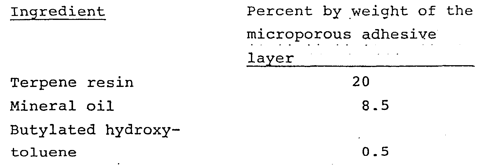
- Following the procedure of Example 1 but employing the following ingredients in microporous
adhesive layer 31 of component C other skin barriers within the scope of this invention are prepared. The ingredients are listed in percent by weight of the adhesive layer.

Claims (22)
including a first component comprising an adhesive layer and an outer polymeric film said first component having a centrally located stomal opening adapted to fit the skin barrier around a stoma, a second component comprising a concentrically shaped coupling element including an outwardly extending flange wherein said flange is permanently affixed to the polymeric film of said first component in an area surrounding said stomal opening, and a third component comprising a microporous adhesive layer and an outer porous backing layer said microporous adhesive layer overlapping said coupling element flange and polymeric film and extending beyond the borders of said first component.
Priority Applications (1)
| Application Number | Priority Date | Filing Date | Title |
|---|---|---|---|
| AT82305995T ATE19943T1 (en) | 1981-11-27 | 1982-11-11 | SEALANT FOR OSTOMY ARRANGEMENTS. |
Applications Claiming Priority (2)
| Application Number | Priority Date | Filing Date | Title |
|---|---|---|---|
| US32546581A | 1981-11-27 | 1981-11-27 | |
| US325465 | 1981-11-27 |
Publications (2)
| Publication Number | Publication Date |
|---|---|
| EP0081907A1 true EP0081907A1 (en) | 1983-06-22 |
| EP0081907B1 EP0081907B1 (en) | 1986-05-28 |
Family
ID=23267992
Family Applications (1)
| Application Number | Title | Priority Date | Filing Date |
|---|---|---|---|
| EP19820305995 Expired EP0081907B1 (en) | 1981-11-27 | 1982-11-11 | Sealing means for ostomy appliances |
Country Status (10)
| Country | Link |
|---|---|
| EP (1) | EP0081907B1 (en) |
| JP (1) | JPS58103452A (en) |
| AT (1) | ATE19943T1 (en) |
| AU (1) | AU567864B2 (en) |
| CA (1) | CA1187368A (en) |
| DE (1) | DE3271449D1 (en) |
| DK (1) | DK159641C (en) |
| IE (1) | IE54788B1 (en) |
| NO (1) | NO156514C (en) |
| ZA (1) | ZA827903B (en) |
Cited By (15)
| Publication number | Priority date | Publication date | Assignee | Title |
|---|---|---|---|---|
| EP0092999A2 (en) * | 1982-04-22 | 1983-11-02 | E.R. Squibb & Sons, Inc. | Dressing |
| GB2148716A (en) * | 1983-11-01 | 1985-06-05 | Craig Med Prod Ltd | Ostomy appliance |
| EP0146367A2 (en) * | 1983-12-19 | 1985-06-26 | E.R. Squibb & Sons, Inc. | Ostomy appliance |
| EP0206646A2 (en) * | 1985-06-20 | 1986-12-30 | E.R. Squibb & Sons, Inc. | Attachment assembly for use on the human skin |
| US4723951A (en) * | 1985-07-15 | 1988-02-09 | Craig Medical Products Ltd. | Gas filter arrangement for ostomy or ileostomy bags |
| FR2635261A1 (en) * | 1988-08-10 | 1990-02-16 | Matysiak Lucien | DEVICE FOR THE POST-OPERATIVE APPARATUS OF LATERAL COLOSTOMY |
| EP0315333A3 (en) * | 1987-11-02 | 1990-08-01 | Dow Corning Corporation | Moldable elastomeric pressure sensitive adhesives |
| EP0591898A1 (en) * | 1992-10-05 | 1994-04-13 | Minnesota Mining And Manufacturing Company | Adhesive compositions, wound dressings and methods |
| WO1999011302A1 (en) * | 1997-08-29 | 1999-03-11 | Coloplast A/S | A pressure sensitive adhesive composition |
| US6437038B1 (en) | 1998-03-12 | 2002-08-20 | Coloplast | Pressure sensitive adhesive composition |
| GB2397230A (en) * | 2003-01-16 | 2004-07-21 | Clinimed | A support for an ostomy bag |
| GB2405348B (en) * | 2002-07-06 | 2005-11-16 | Kapitex Healthcare Ltd | Tracheostoma cannula mounting |
| US7192420B2 (en) * | 2003-08-08 | 2007-03-20 | Whiteford Bruce W | Ostomy adapter with multiple adhesives for reliable sealing |
| GB2432120A (en) * | 2005-11-09 | 2007-05-16 | Welland Medical Ltd | A support for an ostomy device with silicone adhesive |
| DE102010048316A1 (en) * | 2010-10-14 | 2012-04-19 | Primed Halberstadt Medizintechnik Gmbh | Ventilation device with a holder for speaking valves and / or heat-moisture exchanger without cannula attachment |
Families Citing this family (7)
| Publication number | Priority date | Publication date | Assignee | Title |
|---|---|---|---|---|
| US4553967A (en) * | 1983-10-14 | 1985-11-19 | E. R. Squibb & Sons, Inc. | Wound care and drainage system having hand access port |
| US4710182A (en) * | 1986-12-04 | 1987-12-01 | Hollister Incorporated | Ostomy appliance and method of making |
| JPS63186416U (en) * | 1987-05-23 | 1988-11-30 | ||
| US4973323A (en) * | 1989-09-01 | 1990-11-27 | Hollister Incorporated | Ostomy appliance |
| US20050096611A1 (en) * | 2003-10-30 | 2005-05-05 | Stoyer Brian C. | Multi-adhesive medical appliance |
| SE0500062A0 (en) * | 2005-01-11 | 2006-07-12 | Moelnlycke Health Care Ab | Component to facilitate attachment of an ostomy dressing to the skin |
| US20070185464A1 (en) * | 2006-02-03 | 2007-08-09 | Bristol-Myers Squibb Company | Ostomy appliance with recovery resistant moldable adhesive |
Citations (6)
| Publication number | Priority date | Publication date | Assignee | Title |
|---|---|---|---|---|
| GB839818A (en) * | 1957-08-01 | 1960-06-29 | Jacobsen & Frederiksen As | Improvements in or relating to a colostomy container |
| CH531353A (en) * | 1969-06-23 | 1972-12-15 | Minnesota Mining & Mfg | Sealing ring for surgical drainage bags |
| US3712304A (en) * | 1970-11-17 | 1973-01-23 | A Marsan | Starch seal and appliance for ostomy |
| US3804091A (en) * | 1972-09-18 | 1974-04-16 | Hollister Inc | Ostomy appliance |
| US3814648A (en) * | 1971-06-30 | 1974-06-04 | A Brondberg | Method of manufacturing a colostomy,ileostomy or ureterostomy bag |
| EP0024253A1 (en) * | 1979-08-08 | 1981-02-25 | Brigitte De Zaepffel | Ileostomy bag |
Family Cites Families (2)
| Publication number | Priority date | Publication date | Assignee | Title |
|---|---|---|---|---|
| US3906951A (en) * | 1974-08-05 | 1975-09-23 | Squibb & Sons Inc | Stomal device including means to prolong attachment of flange |
| IE46487B1 (en) * | 1977-03-31 | 1983-06-29 | Hollister Inc | Improvements relating to drainage pouches |
-
1982
- 1982-10-28 ZA ZA827903A patent/ZA827903B/en unknown
- 1982-11-04 AU AU90161/82A patent/AU567864B2/en not_active Expired
- 1982-11-09 CA CA000415175A patent/CA1187368A/en not_active Expired
- 1982-11-11 AT AT82305995T patent/ATE19943T1/en not_active IP Right Cessation
- 1982-11-11 EP EP19820305995 patent/EP0081907B1/en not_active Expired
- 1982-11-11 DE DE8282305995T patent/DE3271449D1/en not_active Expired
- 1982-11-25 NO NO823958A patent/NO156514C/en not_active IP Right Cessation
- 1982-11-25 IE IE2805/82A patent/IE54788B1/en not_active IP Right Cessation
- 1982-11-26 DK DK529082A patent/DK159641C/en not_active IP Right Cessation
- 1982-11-26 JP JP57208372A patent/JPS58103452A/en active Granted
Patent Citations (6)
| Publication number | Priority date | Publication date | Assignee | Title |
|---|---|---|---|---|
| GB839818A (en) * | 1957-08-01 | 1960-06-29 | Jacobsen & Frederiksen As | Improvements in or relating to a colostomy container |
| CH531353A (en) * | 1969-06-23 | 1972-12-15 | Minnesota Mining & Mfg | Sealing ring for surgical drainage bags |
| US3712304A (en) * | 1970-11-17 | 1973-01-23 | A Marsan | Starch seal and appliance for ostomy |
| US3814648A (en) * | 1971-06-30 | 1974-06-04 | A Brondberg | Method of manufacturing a colostomy,ileostomy or ureterostomy bag |
| US3804091A (en) * | 1972-09-18 | 1974-04-16 | Hollister Inc | Ostomy appliance |
| EP0024253A1 (en) * | 1979-08-08 | 1981-02-25 | Brigitte De Zaepffel | Ileostomy bag |
Cited By (34)
| Publication number | Priority date | Publication date | Assignee | Title |
|---|---|---|---|---|
| EP0092999A3 (en) * | 1982-04-22 | 1986-02-26 | E.R. Squibb & Sons, Inc. | Dressing, granules, and their use in treating wounds |
| EP0092999A2 (en) * | 1982-04-22 | 1983-11-02 | E.R. Squibb & Sons, Inc. | Dressing |
| GB2148716A (en) * | 1983-11-01 | 1985-06-05 | Craig Med Prod Ltd | Ostomy appliance |
| EP0276043A3 (en) * | 1983-12-19 | 1989-05-03 | Craig Medical Products Limited | Ostomy appliance |
| EP0146367A3 (en) * | 1983-12-19 | 1985-11-21 | Craig Medical Products Limited | Ostomy appliance |
| US4701169A (en) * | 1983-12-19 | 1987-10-20 | Craig Medical Products | Ostomy appliance with improved attachment means |
| EP0276042A2 (en) * | 1983-12-19 | 1988-07-27 | E.R. Squibb & Sons, Inc. | Ostomy aplliance |
| EP0276043A2 (en) * | 1983-12-19 | 1988-07-27 | E.R. Squibb & Sons, Inc. | Ostomy appliance |
| EP0276898A2 (en) * | 1983-12-19 | 1988-08-03 | E.R. Squibb & Sons, Inc. | Ostomy appliance |
| EP0146367A2 (en) * | 1983-12-19 | 1985-06-26 | E.R. Squibb & Sons, Inc. | Ostomy appliance |
| EP0276898A3 (en) * | 1983-12-19 | 1989-05-03 | Craig Medical Products Limited | Ostomy appliance |
| EP0276042A3 (en) * | 1983-12-19 | 1989-05-17 | Craig Medical Products Limited | Ostomy aplliance |
| EP0206646A2 (en) * | 1985-06-20 | 1986-12-30 | E.R. Squibb & Sons, Inc. | Attachment assembly for use on the human skin |
| EP0206646A3 (en) * | 1985-06-20 | 1987-06-10 | E.R. Squibb & Sons, Inc. | Attachment assembly for use on the human skin |
| US4723951A (en) * | 1985-07-15 | 1988-02-09 | Craig Medical Products Ltd. | Gas filter arrangement for ostomy or ileostomy bags |
| EP0315333A3 (en) * | 1987-11-02 | 1990-08-01 | Dow Corning Corporation | Moldable elastomeric pressure sensitive adhesives |
| EP0356363A1 (en) * | 1988-08-10 | 1990-02-28 | Lucien Matysiak | Device for the post-operative assembly of a lateral colostomy |
| US5026361A (en) * | 1988-08-10 | 1991-06-25 | Lucien Matysiak | Post-operative fitting device for a lateral colostomy |
| FR2635261A1 (en) * | 1988-08-10 | 1990-02-16 | Matysiak Lucien | DEVICE FOR THE POST-OPERATIVE APPARATUS OF LATERAL COLOSTOMY |
| EP0591898A1 (en) * | 1992-10-05 | 1994-04-13 | Minnesota Mining And Manufacturing Company | Adhesive compositions, wound dressings and methods |
| US5622711A (en) * | 1992-10-05 | 1997-04-22 | Minnesota Mining And Manufacturing Company | Adhesive composition for use as a wound dressing or ostomy/prosthesis adhesive |
| US5633010A (en) * | 1992-10-05 | 1997-05-27 | Minnesota Mining And Manufacturing Company | Adhesive compositions, wound dressings and methods |
| WO1999011302A1 (en) * | 1997-08-29 | 1999-03-11 | Coloplast A/S | A pressure sensitive adhesive composition |
| US6451883B1 (en) | 1997-08-29 | 2002-09-17 | Coloplast A/S | Pressure Sensitive Adhesive Composition |
| US6437038B1 (en) | 1998-03-12 | 2002-08-20 | Coloplast | Pressure sensitive adhesive composition |
| US7506647B2 (en) | 2002-07-06 | 2009-03-24 | Kapitex Healthcare Limited | Tracheostoma cannula mounting |
| GB2405348B (en) * | 2002-07-06 | 2005-11-16 | Kapitex Healthcare Ltd | Tracheostoma cannula mounting |
| GB2397230A (en) * | 2003-01-16 | 2004-07-21 | Clinimed | A support for an ostomy bag |
| AU2004204399B2 (en) * | 2003-01-16 | 2007-11-22 | Clinimed (Holdings) Limited | A support for an ostomy bag |
| GB2397230B (en) * | 2003-01-16 | 2006-08-23 | Clinimed | A support for an ostomy bag |
| US7192420B2 (en) * | 2003-08-08 | 2007-03-20 | Whiteford Bruce W | Ostomy adapter with multiple adhesives for reliable sealing |
| GB2432120A (en) * | 2005-11-09 | 2007-05-16 | Welland Medical Ltd | A support for an ostomy device with silicone adhesive |
| DE102010048316A1 (en) * | 2010-10-14 | 2012-04-19 | Primed Halberstadt Medizintechnik Gmbh | Ventilation device with a holder for speaking valves and / or heat-moisture exchanger without cannula attachment |
| DE102010048316B4 (en) * | 2010-10-14 | 2016-02-11 | Primed Halberstadt Medizintechnik Gmbh | Ventilation device with a holder for speaking valves and / or heat-moisture exchanger without cannula attachment |
Also Published As
| Publication number | Publication date |
|---|---|
| DK159641B (en) | 1990-11-12 |
| CA1187368A (en) | 1985-05-21 |
| NO823958L (en) | 1983-05-30 |
| ATE19943T1 (en) | 1986-06-15 |
| EP0081907B1 (en) | 1986-05-28 |
| AU567864B2 (en) | 1987-12-10 |
| DK529082A (en) | 1983-05-28 |
| NO156514C (en) | 1987-10-07 |
| DK159641C (en) | 1991-04-08 |
| AU9016182A (en) | 1983-06-02 |
| IE822805L (en) | 1983-05-27 |
| ZA827903B (en) | 1983-08-31 |
| DE3271449D1 (en) | 1986-07-03 |
| IE54788B1 (en) | 1990-02-14 |
| NO156514B (en) | 1987-06-29 |
| JPS58103452A (en) | 1983-06-20 |
| JPH0341178B2 (en) | 1991-06-21 |
Similar Documents
| Publication | Publication Date | Title |
|---|---|---|
| US4775374A (en) | Skin barrier for use by ostomates | |
| EP0081907B1 (en) | Sealing means for ostomy appliances | |
| US5074852A (en) | Occlusive attaching device for ostomy appliance | |
| US4393080A (en) | Adhesive compositions | |
| US4253460A (en) | Ostomy adhesive | |
| EP1541180B1 (en) | Pressure sensitive adhesive composition for medical use | |
| EP1066357B1 (en) | A pressure sensitive adhesive composition | |
| US4551490A (en) | Adhesive composition resistant to biological fluids | |
| CN1233945B (en) | Ostomy appliance | |
| AU598068B2 (en) | Ostomy appliance and method of making | |
| US5593397A (en) | Fecal collector with elastic attachment patch | |
| US4192785A (en) | Ostomy adhesive | |
| EP0984751B1 (en) | An ostomy appliance | |
| EP0954342B2 (en) | Ostomy appliance and wound drainage device | |
| US6293930B1 (en) | Low-profile ostomy faceplate with recessed coupling ring | |
| EP1440697B1 (en) | Hydrocolloid adhesive tape | |
| CN102883691A (en) | Iris diaphragm seal for an ostomy bag | |
| EP0122344B1 (en) | Adhesive composition | |
| JPH06285103A (en) | Two-piece ostomy apparatus | |
| DK174511B1 (en) | Sealing device for ostomy appliances - has first adhesive component to fit round stoma, coupling element and porous adhesive element to contact skin at distance from stoma | |
| GB2142543A (en) | Stoma bag with locking ring | |
| DD298046A5 (en) | OCCLUSIVE INSTALLATION EQUIPMENT FOR OSTOMATIC INSPECTION |
Legal Events
| Date | Code | Title | Description |
|---|---|---|---|
| PUAI | Public reference made under article 153(3) epc to a published international application that has entered the european phase |
Free format text: ORIGINAL CODE: 0009012 |
|
| AK | Designated contracting states |
Designated state(s): AT BE CH DE FR GB IT LI LU NL SE |
|
| 17P | Request for examination filed |
Effective date: 19831214 |
|
| GRAA | (expected) grant |
Free format text: ORIGINAL CODE: 0009210 |
|
| AK | Designated contracting states |
Kind code of ref document: B1 Designated state(s): AT BE CH DE FR GB IT LI LU NL SE |
|
| REF | Corresponds to: |
Ref document number: 19943 Country of ref document: AT Date of ref document: 19860615 Kind code of ref document: T |
|
| ITF | It: translation for a ep patent filed |
Owner name: JACOBACCI & PERANI S.P.A. |
|
| REF | Corresponds to: |
Ref document number: 3271449 Country of ref document: DE Date of ref document: 19860703 |
|
| ET | Fr: translation filed | ||
| PLBE | No opposition filed within time limit |
Free format text: ORIGINAL CODE: 0009261 |
|
| STAA | Information on the status of an ep patent application or granted ep patent |
Free format text: STATUS: NO OPPOSITION FILED WITHIN TIME LIMIT |
|
| 26N | No opposition filed | ||
| ITTA | It: last paid annual fee | ||
| EPTA | Lu: last paid annual fee | ||
| EAL | Se: european patent in force in sweden |
Ref document number: 82305995.1 |
|
| PGFP | Annual fee paid to national office [announced via postgrant information from national office to epo] |
Ref country code: SE Payment date: 20011106 Year of fee payment: 20 |
|
| PGFP | Annual fee paid to national office [announced via postgrant information from national office to epo] |
Ref country code: LU Payment date: 20011108 Year of fee payment: 20 |
|
| PGFP | Annual fee paid to national office [announced via postgrant information from national office to epo] |
Ref country code: FR Payment date: 20011113 Year of fee payment: 20 Ref country code: AT Payment date: 20011113 Year of fee payment: 20 |
|
| PGFP | Annual fee paid to national office [announced via postgrant information from national office to epo] |
Ref country code: GB Payment date: 20011114 Year of fee payment: 20 |
|
| PGFP | Annual fee paid to national office [announced via postgrant information from national office to epo] |
Ref country code: DE Payment date: 20011126 Year of fee payment: 20 |
|
| PGFP | Annual fee paid to national office [announced via postgrant information from national office to epo] |
Ref country code: NL Payment date: 20011129 Year of fee payment: 20 |
|
| PGFP | Annual fee paid to national office [announced via postgrant information from national office to epo] |
Ref country code: CH Payment date: 20011130 Year of fee payment: 20 |
|
| REG | Reference to a national code |
Ref country code: GB Ref legal event code: IF02 |
|
| PGFP | Annual fee paid to national office [announced via postgrant information from national office to epo] |
Ref country code: BE Payment date: 20020121 Year of fee payment: 20 |
|
| PG25 | Lapsed in a contracting state [announced via postgrant information from national office to epo] |
Ref country code: LI Free format text: LAPSE BECAUSE OF EXPIRATION OF PROTECTION Effective date: 20021110 Ref country code: GB Free format text: LAPSE BECAUSE OF EXPIRATION OF PROTECTION Effective date: 20021110 Ref country code: CH Free format text: LAPSE BECAUSE OF EXPIRATION OF PROTECTION Effective date: 20021110 |
|
| PG25 | Lapsed in a contracting state [announced via postgrant information from national office to epo] |
Ref country code: NL Free format text: LAPSE BECAUSE OF EXPIRATION OF PROTECTION Effective date: 20021111 Ref country code: LU Free format text: LAPSE BECAUSE OF EXPIRATION OF PROTECTION Effective date: 20021111 Ref country code: AT Free format text: LAPSE BECAUSE OF EXPIRATION OF PROTECTION Effective date: 20021111 |
|
| REG | Reference to a national code |
Ref country code: GB Ref legal event code: PE20 Effective date: 20021110 |
|
| REG | Reference to a national code |
Ref country code: CH Ref legal event code: PL |
|
| NLV7 | Nl: ceased due to reaching the maximum lifetime of a patent |
Effective date: 20021111 |
|
| EUG | Se: european patent has lapsed |