EP0079880A2 - Retaining structure - Google Patents
Retaining structure Download PDFInfo
- Publication number
- EP0079880A2 EP0079880A2 EP82890167A EP82890167A EP0079880A2 EP 0079880 A2 EP0079880 A2 EP 0079880A2 EP 82890167 A EP82890167 A EP 82890167A EP 82890167 A EP82890167 A EP 82890167A EP 0079880 A2 EP0079880 A2 EP 0079880A2
- Authority
- EP
- European Patent Office
- Prior art keywords
- anchoring
- support structure
- prefabricated parts
- building
- parts
- Prior art date
- Legal status (The legal status is an assumption and is not a legal conclusion. Google has not performed a legal analysis and makes no representation as to the accuracy of the status listed.)
- Granted
Links
Images

Classifications
-
- E—FIXED CONSTRUCTIONS
- E02—HYDRAULIC ENGINEERING; FOUNDATIONS; SOIL SHIFTING
- E02D—FOUNDATIONS; EXCAVATIONS; EMBANKMENTS; UNDERGROUND OR UNDERWATER STRUCTURES
- E02D29/00—Independent underground or underwater structures; Retaining walls
- E02D29/02—Retaining or protecting walls
- E02D29/0225—Retaining or protecting walls comprising retention means in the backfill
- E02D29/0233—Retaining or protecting walls comprising retention means in the backfill the retention means being anchors
Definitions
- the invention relates to a method for producing support structures and support structures produced by this method.
- the invention is based on buildings as described in Austrian Patent 367,129.
- loop-shaped or ring-shaped tension members enclose the components in a comprehensive or penetrating manner and connect them to one another in this way.
- the object of the present invention is to create structures which are distinguished by particular stability and structural toughness and in which the tension members are largely included in the composite construction consisting of the components and the backfilling material, by systematically equalizing the backfilling material enforce moderate distribution and high density.
- the structure Furthermore, it is an object of the invention to give the structure a structure which makes it possible to vary its contour to a large extent, and to adapt it to the different local terrain. According to the invention, these objects are primarily achieved by first laying prefabricated parts arranged in approximately the same level in a continuous succession, and connecting them to one another by means of preferably loop-shaped anchoring members and finally backfilling in layers with an embedding backing material embedding these anchoring members.
- the method according to the invention allows place the anchoring elements comfortably on the top, exposed, last inserted layer of the backfill material and embed them in it by applying the next layer of the backfill material.
- This considerably simplifies both the laying of the anchoring members and their anchoring; these anchoring elements can be fixed very easily and conveniently to abutments inside the supporting structure or - in the case of dams and walls - on the opposite the outside of the building.
- the method according to the invention ensures an extremely even distribution of the anchoring members within the building body, which, thanks to this even distribution, can be regarded as a real composite construction.
- the contour-forming finished parts anchored in the interior of the building, emerging on the outside of the building do not need to lie exactly on top of one another in a load-bearing manner and also do not have to form a rigid bond between one another by positive locking of the finished parts, the structure can be in its Shaping can be designed and manufactured completely freely, so that it can be largely adapted to local requirements, taking into account the respective terrain.
- the backfilling material is synchronous with the laying of level coulters of prefabricated parts and the laying of the anchoring elements in each case in step with the production of the respective level material layer in which these anchoring elements run, but also brings additional advantages with regard to water retention in the building structure.
- the individual anchoring members can in each case be coated with a water-conductive material before the next higher layer of the backfill material is introduced.
- These anchoring elements can be placed on the free upper side of the last layer of backfill material introduced in each case with a minimum of time and effort, and in this state and during the laying phase they can be easily embedded in water-conductive material.
- small trenches to be filled with the water-conductive material can be provided for the anchoring members in the uppermost layer of the backfill material, or such material can be poured onto the anchoring members lying on this layer in small walls.
- the anchoring members embedded in such a water-conductive material result in an extremely effective duct system, particularly suitable for cohesive soils to reduce the pore water pressure in the structure, which penetrates this structure with a high density as an evenly distributed network.
- a retaining wall composed of any prefabricated parts 1 is equipped by means of anchoring links 2, which can be attached to the prefabricated parts 1 as desired, preferably they loop around parts of these prefabricated parts 1.
- the structure rests on the solid floor 3.
- the individual anchoring members 2 consist, for example, of plastic-coated steels, wires, ropes and so-called steel cords, of plastic or glass fiber strands or rods, preferably of aramids, polyesters or the like. Plastics, and are attached to any design anchor 4 anchored.
- the anchoring members 2 are embedded in a water-permeable material 5 and penetrate the backfill material 6. The excess water accumulating in this backfill 6 is discharged to the outside of the building through the strands formed from this water-conductive material 5.
- the prefabricated parts 1 can be freely offset in their horizontal levels because they do not need any connection in the vertical direction and are completely independent of one another.
- FIG. 2 shows, in the same way as FIG. 1, a building in which the anchoring members 2 embedded in the backfill material 6 are anchored to the solid floor 3 with their ends on the slope side.
- the support structure according to FIG. 3 is a dam that only has a covering made of prefabricated parts 1 on one side, which at most - in areas to be left free for this purpose - can be seen with vegetation.
- the water accumulating in the dam body is fed to the clad flank of the building via the strands consisting of the water-conductive material 5 and enveloping the obliquely inclined anchoring members 2.
- both sides of such a dam are to be equipped with a covering consisting of prefabricated parts 1, the anchoring members 2 can be led away to one of the two flanks and arranged inclined. If - on the left in Figure 4 - the outside is at least occasionally and temporarily flushed with water 7, the water seeping through the joints between the prefabricated parts can be drained into the interior of the building and collected, for example, in a shaft with a drainage channel or on the opposite free flank of the Building are guided, as shown in Figure 4.
- the anchoring members 2 can also be inclined towards the two flanks starting from the center of the building.
- Figure 6 shows on a larger scale in cross section an anchoring member 2 which is embedded in a loose or bound granular water-conductive material 5, i.e. in a gravel bed or in a mass bound by an initially pourable, later hardening binder, e.g. Einkornbeton.
- the water-conductive material for covering the anchoring members 2 and for draining off the water obtained can also be obtained from drainage pipes or the like.
- the production of the water-conductive strands does not cause any appreciable additional costs, because their production can be carried out at the same time as the anchoring members are laid and the backfill material 6 is introduced in layers.
- Figures 9 to 11 show different structures in which the prefabricated parts 1 embody a closed cover of the backfill material 6.
- the finished parts 1 are wrapped around a projecting part 1 ', extensively closed flexible anchoring members 2 anchored and held in the backfill 6; such an embodiment is, for example, well suited for the support of fillings, dams and landfills.
- anchoring members 2 instead of being anchored to only one prefabricated part 1, such anchoring members 2 can also loop around several, for example groups or pairs of such prefabricated parts, as is indicated by dashed lines.
- the individual prefabricated parts 1 can also be looped around by several anchoring members 2.
- the anchors 4 provided for anchoring the anchoring members 2 in the backfilling can in principle be of any design, e.g. also consist of precast concrete elements, which are wrapped around by the anchoring members 2, remain invisible and can therefore be arranged in any size, shape and number, since they only serve the purpose of holding the anchoring members 2 in the backing material 6.
- FIG. 10 shows C-shaped precast concrete parts 1, in which the legs facing the backfill 6 lie directly on one another and thus embody a closed, erosion-proof cover of the backfill 6 together with the webs facing the visible surface.
- the anchoring members 2 can easily be attached to the legs protruding into the back filling 6, e.g. on projections l 'of these legs, are anchored by looping.
- FIG. 11 shows prefabricated parts 1 with an angular profile, the vertically upright legs of which are at a distance from one another in the horizontal direction, which can be bridged, for example, with plates 10, mats, nonwovens or coarse fillings in order to achieve a desirable closed armoring of the backfill material 6.
- the lying leg of the angle-shaped Vertigmaschine 1 nen again for fixing the anchoring members 2 by means of projections 1. 1
- the anchors 4 used to anchor the anchoring members 2 are arranged in the interior of the building against erosion, but also against other dangers, such as, for example, against willful damage.
- seals which are to be arranged between the superimposed and superimposed prefabricated parts 1 of a prefabricated assembly which completely covers the backfill material and which can be formed either from circularly profiled strands, cords 11 or from band-shaped strip seals 12.
- the anchors 4 embedded in the backfill material 6 for the loop-shaped anchoring members 2 consist of curved shells.
- the prefabricated parts 1 lie with their faces on each other like a checkerboard, and their position can also be varied as desired in the transverse direction of the building
- the prefabricated elements 1 show the figures 15 and 16.
Abstract
Description
Die Erfindung betrifft ein Verfahren zur Herstellung von Stützbauwerken sowie nach diesem Verfahren hergestellte Stützbauwerke.The invention relates to a method for producing support structures and support structures produced by this method.
Insbesondere geht die Erfindung von Bauwerken aus, wie sie in der österreichischen Patentschrift 367 129 beschrieben sind. Solche Bauwerke bestehen aus einer Anzahl übereinander angeordneter, zumindest teilweise in einem Hinterfüllungs= material eingebetteter und dieses stützender Bauelemente, mit Zuggliedern, die sich im wesentlichen waagrecht zwischen zumindest einem im Bereich der Außenseite des Bauwerkes befindlichen, dessen Kontur bestimmenden Bauelement und zumindest einem in dem Hinterfüllungsmaterial eingebetteten Bauelement oder zu einem an der gegenüberliegenden Seite des Bauwerkes angeordneten Bauelement erstrecken und das in Schichten eingebrachte Hinterfüllungsmaterial durch= setzen, wobei diese Schichten von dem gegen die Bauelemente wirkenden Bodendruck voneinander unabhängig verspannt und zusammengehalten sind.In particular, the invention is based on buildings as described in Austrian Patent 367,129. Such structures consist of a number of superimposed components, at least partially embedded in a backfill = material and supporting them, with tension members that are essentially horizontal between at least one component located in the area of the outside of the structure, the contour of which determines the component and at least one in the Backfill embedded component or extend to a component arranged on the opposite side of the building and enforce the backfill material introduced into layers, these layers being independently braced and held together by the ground pressure acting against the components.
Diese schlaufen- oder ringförmig gestalteten Zugglieder schließen die Bauelemente umfassend oder durchsetzend ein und verbinden sie auf diese Weise miteinander.These loop-shaped or ring-shaped tension members enclose the components in a comprehensive or penetrating manner and connect them to one another in this way.
Aufgabe vorliegender Erfindung ist es, Bauwerke zu schaffen, die sich durch besondere Standfestigkeit und strukturelle Zähigkeit auszeichnen und bei denen die Zugglieder weitest= gehend in die aus den Bauelementen und dem Hinterfüllungs= material bestehende Verbundkonstruktion einbezogen sind, indem sie das Hinterfüllungsmaterial systematisch in gleich= mäßiger Verteilung und mit hoher Dichte durchsetzen.The object of the present invention is to create structures which are distinguished by particular stability and structural toughness and in which the tension members are largely included in the composite construction consisting of the components and the backfilling material, by systematically equalizing the backfilling material enforce moderate distribution and high density.
Weiters ist es Aufgabe der Erfindung, dem Bauwerk eine Struktur zu verleihen, die es ermöglicht, dessen Kontur wünschenswert weitgehend zu variieren und sie den örtlichen verschiedenen Geländeverhältnissen individuell anzupassen. Diese Aufgaben werden erfindungsgemäß primär dadurch gelöst, daß in steter Aufeinanderfolge zunächst etwa im selben Niveau angeordnete Fertigteile verlegt, sowie mittels vorzugsweise schlaufenförmig geführter Ver= ankerungsglieder miteinander verbunden und schließlich schichtweise mit einem diese Verankerungsglieder ein= bettenden Hinterfüllungsmaterial'hinterfüllt werden.Furthermore, it is an object of the invention to give the structure a structure which makes it possible to vary its contour to a large extent, and to adapt it to the different local terrain. According to the invention, these objects are primarily achieved by first laying prefabricated parts arranged in approximately the same level in a continuous succession, and connecting them to one another by means of preferably loop-shaped anchoring members and finally backfilling in layers with an embedding backing material embedding these anchoring members.
Während nach einem bekannten Verfahren die Verankerungs= glieder, die sich in das zu stützende Material erstrecken, in Bohrungen verlegt wurden, die von der Luftseite des Materiales ausgehend mit erheblichem Zeit-, Mühe- und Kostenaufwand angefertigt werden mußten, erlaubt es das erfindungsgemäße Verfahren, die Verankerungsglieder bequem auf die jeweils oberste, freiliegende, letzteingebrachte Schicht des Hinterfüllungsmateriales aufzulegen und durch Aufbringung der nächsten Schicht des Hinterfüllungsmateria= les darin einzubetten. Dadurch vereinfacht sich sowohl das Verlegen der Verankerungsglieder erheblich als auch deren Verankerung; man kann diese Verankerungsglieder höchst einfach und bequem an Widerlagern im Inneren des Stützbau= werkes oder - bei Dämmen und Wänden - an der gegenüberliegen= den Außenseite des Bauwerkes fixieren. Außerdem gewährleis= tet das erfindungsgemäße Verfahren eine überaus gleichmäßige Verteilung der Verankerungsglieder innerhalb des Bauwerks= körpers, der dank dieser gleichmäßigen Verteilung als echte Verbundkonstruktion angesehen werden kann.While, according to a known method, the anchoring elements, which extend into the material to be supported, were laid in bores which had to be made from the air side of the material with considerable time, effort and cost, the method according to the invention allows place the anchoring elements comfortably on the top, exposed, last inserted layer of the backfill material and embed them in it by applying the next layer of the backfill material. This considerably simplifies both the laying of the anchoring members and their anchoring; these anchoring elements can be fixed very easily and conveniently to abutments inside the supporting structure or - in the case of dams and walls - on the opposite = the outside of the building. In addition, the method according to the invention ensures an extremely even distribution of the anchoring members within the building body, which, thanks to this even distribution, can be regarded as a real composite construction.
Da bei der Durchführung des erfindungsgemäßen Verfahrens die im Inneren des Bauwerkes verankerten, an der Außenseite des Bauwerkes zutagetretenden, konturbildenden Fertigteile nicht lastabtragend exakt aufeinanderliegen brauchen und auch keinen starren, durch Formschluß der Fertigteile unter= einander fixierten Verband bilden müssen, kann das Bauwerk in seiner Formgebung völlig frei konzipiert und angefertigt werden, so daß es unter Bedachtnahme auf die jeweilige Ge= ländeform jeweils weitgehend den örtlichen Erfordernissen angepaßt werden kann.Since when carrying out the method according to the invention, the contour-forming finished parts anchored in the interior of the building, emerging on the outside of the building, do not need to lie exactly on top of one another in a load-bearing manner and also do not have to form a rigid bond between one another by positive locking of the finished parts, the structure can be in its Shaping can be designed and manufactured completely freely, so that it can be largely adapted to local requirements, taking into account the respective terrain.
Die erfindungsgemäße Bauweise, derzufolge das Hinterfüllungs= material synchron mit der Verlegung niveaugleicher Scharen von Fertigteilen eingebracht wird und auch die Verlegung der Verankerungsglieder jeweils im Gleichschritt mit der Herstellung der jeweils niveaugleichen Materialschicht, in der diese Verankerungsglieder verlaufen, erfolgt, bringt aber auch noch zusätzliche Vorteile hinsichtlich der Wasserhaltung im Bauwerkskörper.The construction according to the invention, consequently the backfilling material is synchronous with the laying of level coulters of prefabricated parts and the laying of the anchoring elements in each case in step with the production of the respective level material layer in which these anchoring elements run, but also brings additional advantages with regard to water retention in the building structure.
Nach einer bevorzugten Ausführungsform des Verfahrens können nämlich die einzelnen Verankerungsglieder jeweils vor dem Einbringen der nächsthöheren Schicht des Hinter= füllungsmateriales mit einem wasserleitfähigen Material umhüllt werden. Man kann diese Verankerungsglieder mit minimalem Zeit- und Müheaufwand auf die freie Oberseite der jeweils zuletzt eingebrachten Schicht des Hinterfüllungs= materiales auflegen und kann sie in diesem Zustand und in der Phase ihrer Verlegung unschwer in wasserleitfähigem Material einbetten. Beispielsweise kann man für die Ver= ankerungsglieder kleine mit dem wasserleitfähigen Material zu füllende Gräben in der obersten Schicht des Hinter= füllungsmateriales vorsehen oder man kann auf die auf dieser Schicht aufliegenden Verankerungsglieder solches Material in kleinen Wällen aufschütten. In jedem Fall ergeben die in solches wasserleitfähiges Material eingebetteten Ver= ankerungsglieder ein überaus wirksames, insbesondere bei bindigen Böden zur Verringerung des Porenwasserdruckes im Bauwerkskörper geeignetes Kanalsystem, das diesen Bauwerks= körper mit hoher Dichte als gleichmäßig verteiltes Netzwerk durchsetzt.According to a preferred embodiment of the method, the individual anchoring members can in each case be coated with a water-conductive material before the next higher layer of the backfill material is introduced. These anchoring elements can be placed on the free upper side of the last layer of backfill material introduced in each case with a minimum of time and effort, and in this state and during the laying phase they can be easily embedded in water-conductive material. For example, small trenches to be filled with the water-conductive material can be provided for the anchoring members in the uppermost layer of the backfill material, or such material can be poured onto the anchoring members lying on this layer in small walls. In any case, the anchoring members embedded in such a water-conductive material result in an extremely effective duct system, particularly suitable for cohesive soils to reduce the pore water pressure in the structure, which penetrates this structure with a high density as an evenly distributed network.
Weitere Vorteile der erfindungsgemäßen Lösung ergeben sich, wenn die an der Außenseite des Bauwerkes zutagetretenden Betonfertigteile eine das Hinterfüllungsmaterial durchgehend abdeckende und gegen Erosion befestigende Schutzverbauung bilden. Die Möglichkeit, die Fertigteile zu einer solchen geschlossenen Panzerung des Hinterfüllungsmateriales zu= sammenzufügen, ergibt sich letzten Endes daraus, daß jeder Fertigteile mit Hilfe der Verankerungsglieder in der Hinter= füllung verankert und dadurch- unabhängig von den anderen - in dem Bauwerksverband festgehalten ist.Further advantages of the solution according to the invention result if the prefabricated concrete parts emerging on the outside of the building form a protective covering that continuously covers the backfill material and secures it against erosion. The possibility of assembling the prefabricated parts to form such a closed armor of the backfill material ultimately results from the fact that each prefabricated part is anchored in the backfill with the aid of the anchoring members and is thereby - independent of the others - retained in the structure association.
Zahlreiche weitere Erfindungsmerkmale sind der besseren Verständlichkeit wegen nachstehend an Hand der Zeichnungen erläutert, die verschiedene Ausführungsbeispiele erfin= dungsgemäßer Stützbauwerke veranschaulichen. Im einzelnen zeigen die
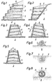
Figuren 1 bis 5 in schematischen Querschnitten verschieden gestaltete Stützbauwerke, dieFiguren 6 bis 8 zeigen in Querschnitten größeren Maßstabes die Einbettung der Verankerungsglieder im Hinterfüllungs= material, die- Figur 9 ist die Draufsicht auf eine fertiggestellte Schicht eines erfindungsgemäßen Bauwerkes, die
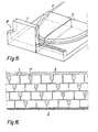
Figuren 10 und 11 zeigen wiederum schematische Querschnitte durch solche Stützbauwerke, dieFigur 12 zeigt in einem Querschnitt die Möglichkeiten einer Abdichtung aufeinanderliegender Fertigteilscharen solcher Bauwerke, die- Figur 13 stellt schaubildlich ein erfindungsgemäßes Bauwerk während dessen Herstellung dar und
- Figur 14 zeigt gleichfalls schaubildlich in größerem Maßstab einen einzelnen Fertigteil für ein solches Bauwerk.
- Figur 15 zeigt eine Variante solcher Fertigteile schaubild= lich und die
- Figur 16 ist die Vorderansicht eines aus solchen Fertigteilen nach Figur 15 hergestellten Bauwerkes.
- Figures 1 to 5 in schematic cross sections of differently designed support structures
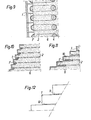
- Figures 6 to 8 show in cross sections on a larger scale the embedding of the anchoring members in the backfill material
- FIG. 9 is a top view of a finished layer of a building according to the invention
- FIGS. 10 and 11 again show schematic cross sections through such supporting structures that
- Figure 12 shows in a cross section the possibilities of sealing superimposed panels of such structures, the
- FIG. 13 shows a structure according to the invention during its manufacture and
- FIG. 14 likewise shows a single prefabricated part for such a structure on a larger scale.
- FIG. 15 shows a variant of such finished parts
- FIG. 16 is the front view of a building made from such prefabricated parts according to FIG. 15.
Gemäß Figur 1 ist eine aus beliebig gestaltbaren Fertig= teilen 1 zusammengesetzte Stützmauer mittels Verankerungs= gliedern 2 ausgestattet, die an den Fertigteilen 1 beliebig befestigt sein können, vorzugsweise umschlingen sie als Schlaufen oder Schlingen Teile dieser Fertigteile 1. Das Bauwerk ruht auf dem festen Boden 3. Die einzelnen Verankerungsglieder 2 bestehen beispielsweise aus kunst= stoffbeschichten Stählen, Drähten, Seilen und sogenannten Stahl-Cords, aus Kunststoff- oder Glasfasersträngen oder -stäben, vorzugsweise aus Aramiden, Polyestern od.dgl. Kunststoffen, und sind an beliebig gestaltbaren Ankern 4 verankert. Bei dem dargestellten Ausführungsbeispiel sind die Verankerungsglieder 2 in einem wasserdurchlässigen Material 5 eingebettet und durchsetzen das Hinterfüllungs= material 6. Das in dieser Hinterfüllung 6 anfallende überschüssige Wasser wird durch die aus diesem wasserleit= fähigen Material 5 gebildeten Stränge zur Außenseite des Bauwerkes abgeführt.According to FIG. 1, a retaining wall composed of any
Wie die Darstellung lehrt, sind die Fertigteile 1 in ihren horizontalen Niveaus beliebig gegeneinander versetzbar, weil sie in vertikaler Richtung keiner Verbindung miteinan= der bedürfen und völlig unabhängig voneinander sind.As the illustration teaches, the
Figur 2 zeigt in gleicher Weise wie Figur 1 ein Bauwerk, bei dem die im Hinterfüllungsmaterial 6 eingebetteten Verankerungsglieder 2 mit ihren hangseitigen Enden am festen Boden 3 verankert sind.FIG. 2 shows, in the same way as FIG. 1, a building in which the
Bei dem Stützbauwerk nach Figur 3 handelt es sich um einen Damm, der nur an einer Seite eine aus Fertigteilen 1 bestehende Verkleidung trägt, die allenfalls - in hiefür freizulassenden Flächenteilen - mit einem Bewuchs ver= sehen werden kann. Das im Dammkörper anfallende Wasser wird der verkleideten Flanke des Bauwerkes über die aus dem wasserleitfähigen Material 5 bestehenden, die schräg geneigt verlaufenden Verankerungsglieder 2 umhüllenden Stränge zugeführt.The support structure according to FIG. 3 is a dam that only has a covering made of
Sind - gemäß Figur 4 - beide Seiten eines solchen Dammes mit einer aus Fertigteilen 1 bestehenden Verkleidung aus= zustatten, können die Verankerungsglieder 2 nach einer der beiden Flanken abgeführt und geneigt angeordnet wer= den. Wird eine - in Figur 4 linke - Außenseite zumindest fallweise und zeitweise von Wasser 7 bespült, kann das durch die Fugen zwischen den Fertigteilen durchsickernde Wasser in das Innere des Bauwerkes abgeführt und beispiels= weise in einem Schacht mit Entwässerungskanal gesammelt oder zur gegenüberliegenden freien Flanke des Bauwerkes geleitet werden, wie dies die Figur 4 zeigt.If - according to FIG. 4 - both sides of such a dam are to be equipped with a covering consisting of
Man kann aber auch gemäß Figur 5 die Verankerungsglieder 2 von der Mitte des Bauwerkes ausgehend nach beiden Flanken hin geneigt verlaufen lassen.However, according to FIG. 5, the anchoring
Figur 6 zeigt in größerem Maßstab im Schnitt ein Veran= kerungsglied 2, das in einem losen oder gebundenen körnigen wasserleitfähigen Material 5 eingebettet ist, also bei= spielsweise in einer Kiesschüttung oder in einer durch ein zunächst gießfähiges, später erhärtendes Bindemittel gebundenen Masse, z.B. Einkornbeton.Figure 6 shows on a larger scale in cross section an anchoring
Die Einbettung kann - gemäß Figur 6 - dadurch erfolgen, daß das Verankerungsglied 2 zunächst lose auf der zuletzt eingebrachten Schicht des Hinterfüllungsmateriales 6 aufgelegt und sodann mit einem kleinen Wall des wasser= leitfähigen Materiales 5 beschüttet und darin eingerüttelt wird, um eingebettet zu werden.The embedding can - according to Figure 6 - take place in that the
Ebensogut kann man aber auch - gemäß Figur 7 -,in der jeweils obersten Schicht des Hinterfüllungsmateriales 6 kleine Gräben herstellen und in diesen Gräben die Verankerungs= glieder 2 in wasserleitfähigem Material 5 einbetten.However, it is equally possible - according to FIG. 7 - to produce 6 small trenches in the uppermost layer of the backfill material and to embed the anchoring
Schließlich kann - gemäß Figur 7 - das wasserleitfähige Material zur Umhüllung der Verankerungsglieder 2 und zur Ableitung des anfallenden Wassers auch aus Drainagerohren od.dgl. hohlen, zu einem Strang aneinanderreihbaren Fertig= teilen 8 bestehen, die Perforationen 9 ihrer Wandung auf= weisen und/oder aus einem wasserdurchlässigen, porösen Material bestehen.Finally, according to FIG. 7, the water-conductive material for covering the anchoring
Dank dieser erfindungsgemäßen systematischen und hochwirk= samen Entwässerung des Hinterfüllungsmateriales 6 kann im Rahmen der Erfindung auch ansonsten ungeeignetes Material für die Hinterfüllung verwendet werden.Thanks to this systematic and highly effective = draining of the
Dank der erfindungsgemäßen Lösung verursacht die Herstellung der wasserleitfähigen Stränge keine nennenswerten Mehrkosten, weil deren Herstellung gleichzeitig mit dem Verlegen der Verankerungsglieder und mit dem schichtweisen Einbringen des Hinterfüllungsmateriales 6 durchführbar ist.Thanks to the solution according to the invention, the production of the water-conductive strands does not cause any appreciable additional costs, because their production can be carried out at the same time as the anchoring members are laid and the
Die Figuren 9 bis 11 zeigen verschiedene Bauwerke, bei denen die Fertigteile 1 eine geschlossene Abdeckung des Hinterfüllungsmateriales 6 verkörpern.Figures 9 to 11 show different structures in which the
Gemäß der Variante nach Figur 8 sind die Fertigteile 1 mittels einen vorspringenden Teil l' umschlingender, umfanggeschlossener flexibler Verankerungsglieder 2 in der Hinterfüllung 6 verankert und festgehalten; eine solche Ausführungsform eignet sich beispielsweise gut für die Abstützung von Schüttungen, Dämmen und Deponien. Selbstverständlich können solche Verankerungsglieder 2 statt an jeweils nur einem Fertigteil 1 verankert zu sein, auch mehrere, z.B. Gruppen oder Paare solcher Fertigteile, umschlingen, wie dies gestrichelt angedeutet ist. Ander= seits können auch die einzelnen Fertigteile 1 von jeweils mehreren Verankerungsgliedern 2 umschlungen sein.According to the variant according to FIG. 8, the finished
Die zur Verankerung der Verankerungsglieder 2 in der Hinter= füllung vorgesehenen Anker 4 können grundsätzlich beliebig gestaltet sein, z.B. gleichfalls aus Betonfertigteilen bestehen, die von den Verankerungsgliedern 2 umschlungen werden, unsichtbar bleiben und deshalb in beliebiger Größe, Form und Anzahl angeordnet werden können, da sie nur dem Zweck dienen, die Verankerungsglieder 2 im Hinter= füllungsmaterial 6 festzuhalten.The anchors 4 provided for anchoring the anchoring
Figur 10 zeigt C-förmig profilierte Betonfertigteile 1, bei denen die zur Hinterfüllung 6 weisenden Schenkel unmittel= bar aufeinanderliegen und solcherart mit den zur Sichtfläche weisenden Stegen gemeinsam eine geschlossene, erosions= sichere Abdeckung der Hinterfüllung 6 verkörpern. Die Ver= ankerungsglieder 2 können unschwer an den in die Hinter= füllung 6 ragenden Schenkeln, z.B. an Vorsprüngen l' dieser Schenkel, durch Umschlingen verankert werden.FIG. 10 shows C-shaped
Figur 11 zeigt winkelförmig profilierte Fertigteile 1, deren senkrecht aufrechtstehende Schenkel voneinander Abstände in horizontaler Richtung'aufweisen, die beispielsweise mit Platten 10, Matten, Vliesen oder Grobsteinschüttungen über= brückt werden können, um eine wünschenswert geschlossene Panzerung des Hinterfüllungsmateriales 6 zu erzielen. Die liegenden Schenkel dieser winkelförmigen Vertigteile 1 die= nen wiederum zur Befestigung der Verankerungsglieder 2 mittels Vorsprüngen 11.FIG. 11 shows prefabricated
In allen Fällen sind die zur Verankerung der Verankerungs= glieder 2 dienenden Anker 4 im Inneren des Bauwerkes gegen Erosion, aber auch gegen sonstige Gefahren, wie etwa auch gegen mutwillige Beschädigungen geschützt angeordnet.In all cases, the anchors 4 used to anchor the
Die Fig.12 zeigt Abdichtungen, die zwischen den jeweils übereinander- und aufeinanderliegenden Fertigteilen 1 eines das Hinterfüllungsmaterial gänzlich abdeckenden Fertigteilverbandes anzuordnen sind und die entweder aus kreisförmig profilierten Strängen, Schnüren 11 oder aus bandförmigen Streifendichtungen 12 gebildet sein können. In jedem Fall soll eine gewisse zähplastische Nachgiebigkeit des Bauwerkes gewährleistet werden, um bei Bodenbewegungen, z.B. Setzungen der Hinterfüllung 6, eine örtliche Überbeanspruchung und einen durch Spannungs= spitzen verursachten Sprödbruch der Fertigteile 1 aus= zuschließen.12 shows seals which are to be arranged between the superimposed and superimposed
In den Figuren 14 und 15 ist eine weitere Ausgührungs= variante dargestellt, derzufolge die außenliegenden Fertig= teile 1 in Form zweiseitig offener länglicher Kästen und mit vom Boden aufwärts vorspringenden Teilen 11 gestaltet sind, die von den Verankerungsgliedern 2 umschlungen werden. Die im Hinterfüllungsmaterial 6 eingebetteten Anker 4 für die schlaufenförmig geführten Verankerungsglieder 2 bestehen aus bogenförmig gestalteten Schalen. Die Fertig= teile 1 liegen schachbrettartig versetzt mit ihren Stirn= seiten aufeinander und ihre Lage ist in Querrichtung des Bauwerkes gleichfalls beliebig variierbarIn the figures 14 and 15 a further Ausgührungs = is represented variant, according to which the external Ready =
Eine Variante dieser Ausführungsform der Fertigteile 1 zeigen die Figuren 15 und 16. Die Figur 16 zeigt schau= bildlich ein Paar zusammengehöriger, spiegelbildlich gestalteter Fertigteile l, von denen jeder die Hälfte eines halbkreisförmig profilierten Vorsprunges 11 trägt. Werden diese Fertigteile 1 in spiegelbildlicher Anordnung verlegt, wie dies die Figur 15 zeigt, ergänzen sich die Vorsprünge 1' wie dargestellt und können vom Verankerungsglied 2 schlaufenförmig umschlungen werden. Diese Fertigteile 1 können dank ihrer Gestaltung besonders rationell gefertigt werden, wobei auch noch die Möglichkeit besteht, in den aufrechten Schenkeln dieser winkelförmig profilierten Fertig= teile 1 Ausnehmungen l" vorzusehen, in denen - wie die Figur 16 in einer Vorderansicht des Bauwerkes zeigt - das Hinterfüllungsmaterial 6 vorteilhaft zutagetritt und mit einem Bewuchs versehen werden kann.A variant of this embodiment, the
Claims (21)
Applications Claiming Priority (4)
| Application Number | Priority Date | Filing Date | Title |
|---|---|---|---|
| AT248279A AT362234B (en) | 1978-05-29 | 1979-04-04 | HIGH PRESSURE CENTRIFUGAL PUMP UNIT |
| AT487681A AT380288B (en) | 1981-11-12 | 1981-11-12 | CONSTRUCTION, PREFERABLY STUETZMAUER, DAMM OD. DGL. |
| AT4876/81 | 1981-11-12 | ||
| AT24/82 | 1982-01-05 |
Publications (3)
| Publication Number | Publication Date |
|---|---|
| EP0079880A2 true EP0079880A2 (en) | 1983-05-25 |
| EP0079880A3 EP0079880A3 (en) | 1983-08-03 |
| EP0079880B1 EP0079880B1 (en) | 1986-09-17 |
Family
ID=25598534
Family Applications (1)
| Application Number | Title | Priority Date | Filing Date |
|---|---|---|---|
| EP82890167A Expired EP0079880B1 (en) | 1979-04-04 | 1982-11-12 | Retaining structure |
Country Status (1)
| Country | Link |
|---|---|
| EP (1) | EP0079880B1 (en) |
Cited By (11)
| Publication number | Priority date | Publication date | Assignee | Title |
|---|---|---|---|---|
| DE3516969A1 (en) * | 1985-05-10 | 1986-11-13 | Hans 7932 Munderkingen Reinschütz | Plantable support structure and method for its manufacture |
| GB2261244A (en) * | 1991-11-06 | 1993-05-12 | Vidal Henri Brevets | Facing element and facing system |
| WO1995030057A1 (en) * | 1994-04-30 | 1995-11-09 | Michael John Turner | Ground support |
| US5474405A (en) * | 1993-03-31 | 1995-12-12 | Societe Civile Des Brevets Henri C. Vidal | Low elevation wall construction |
| US5487623A (en) * | 1993-03-31 | 1996-01-30 | Societe Civile Des Brevets Henri C. Vidal | Modular block retaining wall construction and components |
| US5568999A (en) * | 1995-04-03 | 1996-10-29 | The Tensar Corporation | Retaining wall block system |
| US5595460A (en) * | 1994-06-06 | 1997-01-21 | The Tensar Corporation | Modular block retaining wall system and method of constructing same |
| US5624211A (en) * | 1993-03-31 | 1997-04-29 | Societe Civile Des Brevets Henri C. Vidal | Modular block retaining wall construction and components |
| US5797706A (en) * | 1993-06-24 | 1998-08-25 | Societe Civile Des Brevets Henri Vidal | Earth structures |
| WO1998058133A1 (en) * | 1997-06-17 | 1998-12-23 | Northern Stresswall Canada Ltd. | Retaining wall system |
| US20230279631A1 (en) * | 2016-10-04 | 2023-09-07 | Mark Robert Edmund CURTIS | Bulwark structure and method |
Families Citing this family (1)
| Publication number | Priority date | Publication date | Assignee | Title |
|---|---|---|---|---|
| DE3913335A1 (en) * | 1989-04-22 | 1990-10-25 | Rolf Hoelzer | WALL |
Citations (13)
| Publication number | Priority date | Publication date | Assignee | Title |
|---|---|---|---|---|
| FR656692A (en) * | 1927-06-25 | 1929-05-11 | Construction system for quay walls, dikes or retaining walls | |
| US2138037A (en) * | 1937-12-29 | 1938-11-29 | Orley B Lane | Earth retainer |
| FR1112729A (en) * | 1954-07-29 | 1956-03-19 | Hersent Sa | Process for the economical construction of quays and retaining walls |
| FR2175291A5 (en) * | 1972-03-08 | 1973-10-19 | Houy Genevieve | |
| CH545892A (en) * | 1973-05-08 | 1974-02-15 | ||
| FR2221588A1 (en) * | 1973-01-18 | 1974-10-11 | Petit Jacques | Reinforced embankment for roads - uses multiple transverse reinforcement wires to maintain walls vert. |
| FR2233857A5 (en) * | 1973-06-14 | 1975-01-10 | Maymont Paul | Temporary retaining or stabilising wall - has front panels anchored by a chain link mesh embedded in the soil |
| US3922864A (en) * | 1974-02-25 | 1975-12-02 | Hilfiker Pipe Co | Stringer for retaining wall construction |
| FR2303121A1 (en) * | 1975-03-03 | 1976-10-01 | Vidal Henri | Reinforced embankment with retaining screen - has reinforcement mesh sections folded into U-shapes so webs form screen (BR210976) |
| GB1485004A (en) * | 1974-09-06 | 1977-09-08 | Environment Sec Of State For T | Reinforced earth structures |
| US4068482A (en) * | 1976-08-02 | 1978-01-17 | Hilfiker Pipe Company | Retaining wall structure using precast stretcher sections |
| DE2805096A1 (en) * | 1977-02-09 | 1978-08-10 | Ebenseer Betonwerke Gmbh | STRUCTURE, PREFERABLY RETAINING WALL, DAM OR DGL. |
| EP0021449A1 (en) * | 1979-06-29 | 1981-01-07 | QUADIE-Bausysteme GmbH | Construction such as a retaining wall or the like |
-
1982
- 1982-11-12 EP EP82890167A patent/EP0079880B1/en not_active Expired
Patent Citations (13)
| Publication number | Priority date | Publication date | Assignee | Title |
|---|---|---|---|---|
| FR656692A (en) * | 1927-06-25 | 1929-05-11 | Construction system for quay walls, dikes or retaining walls | |
| US2138037A (en) * | 1937-12-29 | 1938-11-29 | Orley B Lane | Earth retainer |
| FR1112729A (en) * | 1954-07-29 | 1956-03-19 | Hersent Sa | Process for the economical construction of quays and retaining walls |
| FR2175291A5 (en) * | 1972-03-08 | 1973-10-19 | Houy Genevieve | |
| FR2221588A1 (en) * | 1973-01-18 | 1974-10-11 | Petit Jacques | Reinforced embankment for roads - uses multiple transverse reinforcement wires to maintain walls vert. |
| CH545892A (en) * | 1973-05-08 | 1974-02-15 | ||
| FR2233857A5 (en) * | 1973-06-14 | 1975-01-10 | Maymont Paul | Temporary retaining or stabilising wall - has front panels anchored by a chain link mesh embedded in the soil |
| US3922864A (en) * | 1974-02-25 | 1975-12-02 | Hilfiker Pipe Co | Stringer for retaining wall construction |
| GB1485004A (en) * | 1974-09-06 | 1977-09-08 | Environment Sec Of State For T | Reinforced earth structures |
| FR2303121A1 (en) * | 1975-03-03 | 1976-10-01 | Vidal Henri | Reinforced embankment with retaining screen - has reinforcement mesh sections folded into U-shapes so webs form screen (BR210976) |
| US4068482A (en) * | 1976-08-02 | 1978-01-17 | Hilfiker Pipe Company | Retaining wall structure using precast stretcher sections |
| DE2805096A1 (en) * | 1977-02-09 | 1978-08-10 | Ebenseer Betonwerke Gmbh | STRUCTURE, PREFERABLY RETAINING WALL, DAM OR DGL. |
| EP0021449A1 (en) * | 1979-06-29 | 1981-01-07 | QUADIE-Bausysteme GmbH | Construction such as a retaining wall or the like |
Cited By (15)
| Publication number | Priority date | Publication date | Assignee | Title |
|---|---|---|---|---|
| DE3516969A1 (en) * | 1985-05-10 | 1986-11-13 | Hans 7932 Munderkingen Reinschütz | Plantable support structure and method for its manufacture |
| GB2261244A (en) * | 1991-11-06 | 1993-05-12 | Vidal Henri Brevets | Facing element and facing system |
| GB2261244B (en) * | 1991-11-06 | 1995-09-20 | Vidal Henri Brevets | Earth structure and facing element therefor |
| US5624211A (en) * | 1993-03-31 | 1997-04-29 | Societe Civile Des Brevets Henri C. Vidal | Modular block retaining wall construction and components |
| US5474405A (en) * | 1993-03-31 | 1995-12-12 | Societe Civile Des Brevets Henri C. Vidal | Low elevation wall construction |
| US5487623A (en) * | 1993-03-31 | 1996-01-30 | Societe Civile Des Brevets Henri C. Vidal | Modular block retaining wall construction and components |
| US5507599A (en) * | 1993-03-31 | 1996-04-16 | Societe Civile Des Brevets Henri C. Vidal | Modular block retaining wall construction and components |
| US5797706A (en) * | 1993-06-24 | 1998-08-25 | Societe Civile Des Brevets Henri Vidal | Earth structures |
| WO1995030057A1 (en) * | 1994-04-30 | 1995-11-09 | Michael John Turner | Ground support |
| US5595460A (en) * | 1994-06-06 | 1997-01-21 | The Tensar Corporation | Modular block retaining wall system and method of constructing same |
| US5568999A (en) * | 1995-04-03 | 1996-10-29 | The Tensar Corporation | Retaining wall block system |
| WO1998058133A1 (en) * | 1997-06-17 | 1998-12-23 | Northern Stresswall Canada Ltd. | Retaining wall system |
| US6113316A (en) * | 1997-06-17 | 2000-09-05 | Northern Stresswall Canada Ltd. | Retaining wall system |
| AU731399B2 (en) * | 1997-06-17 | 2001-03-29 | Northern Stresswall Canada Ltd. | Retaining wall system |
| US20230279631A1 (en) * | 2016-10-04 | 2023-09-07 | Mark Robert Edmund CURTIS | Bulwark structure and method |
Also Published As
| Publication number | Publication date |
|---|---|
| EP0079880B1 (en) | 1986-09-17 |
| EP0079880A3 (en) | 1983-08-03 |
Similar Documents
| Publication | Publication Date | Title |
|---|---|---|
| DE1684357A1 (en) | Method and device for the production of wall structures or the like. | |
| CH666510A5 (en) | ARRANGEMENT FOR CREATING A GROUNDABLE STEEP SLOPE. | |
| DE2628618B2 (en) | Process for building a quay wall in the water and structural element for carrying out the process | |
| EP0079880A2 (en) | Retaining structure | |
| EP2110477A2 (en) | Gabions | |
| EP0234175B1 (en) | Building set for the erection of walls | |
| DE3917357A1 (en) | Embankments and flood dams - prepd. from rammed posts and rock filled netting based on plastic material | |
| DE2618459A1 (en) | METHOD OF FASTENING FLOOR TO EMBROIDERY | |
| DE2646020C2 (en) | Concrete component for a space lattice wall | |
| DE1947249C3 (en) | Method for producing a diaphragm wall in the ground and prefabricated part for carrying out the method | |
| DE2062477A1 (en) | Method and device for protecting and / or stabilizing inclined surfaces | |
| DE3516044C2 (en) | Method of shielding objects from vibrations propagated above the ground | |
| DE102010054364A1 (en) | Method for constructing gabion wall used in construction of e.g. road, involves forming sound-absorbing boundary layer between concrete core and fill material after partial penetration of fresh concrete of core through fill material | |
| EP1054110A1 (en) | Method for forming a vegetation support layer on an sloping earth structure | |
| DE2805096A1 (en) | STRUCTURE, PREFERABLY RETAINING WALL, DAM OR DGL. | |
| EP1514998A1 (en) | Tunnel drainage construction | |
| DE2826324A1 (en) | Retaining wall made of prefabricated concrete beams - has stacked beam and connector assembly filled with granular material | |
| DE2803860C2 (en) | Method of making a retaining wall | |
| AT398994B (en) | PLANTABLE SUPPORT BUILDING AND METHOD FOR THE PRODUCTION THEREOF | |
| DE4126657C1 (en) | Vegetative sound barrier with longitudinal walls - has each wall of longitudinal elements with vertical, tightly packed willow braches | |
| DE202017106103U1 (en) | Wire basket and protective wall against noise and / or flood | |
| DE3335950A1 (en) | Structure designed as a back-filled openwork wall, such as, for example, a supporting wall, a sound-proofing wall or the like | |
| DE102004060090B4 (en) | Component and method for its production | |
| DE2614539C3 (en) | Method and kit for manufacturing slurry tanks | |
| DE10039769C2 (en) | Procedure for stabilizing embankments |
Legal Events
| Date | Code | Title | Description |
|---|---|---|---|
| PUAI | Public reference made under article 153(3) epc to a published international application that has entered the european phase |
Free format text: ORIGINAL CODE: 0009012 |
|
| AK | Designated contracting states |
Designated state(s): AT BE CH DE FR GB IT LI LU NL SE |
|
| PUAL | Search report despatched |
Free format text: ORIGINAL CODE: 0009013 |
|
| AK | Designated contracting states |
Designated state(s): AT BE CH DE FR GB IT LI LU NL SE |
|
| 17P | Request for examination filed |
Effective date: 19840202 |
|
| GRAA | (expected) grant |
Free format text: ORIGINAL CODE: 0009210 |
|
| AK | Designated contracting states |
Kind code of ref document: B1 Designated state(s): AT BE CH DE FR GB IT LI LU NL SE |
|
| REF | Corresponds to: |
Ref document number: 22333 Country of ref document: AT Date of ref document: 19861015 Kind code of ref document: T |
|
| ITF | It: translation for a ep patent filed |
Owner name: BUGNION S.P.A. |
|
| REF | Corresponds to: |
Ref document number: 3273374 Country of ref document: DE Date of ref document: 19861023 |
|
| ET | Fr: translation filed | ||
| PLBI | Opposition filed |
Free format text: ORIGINAL CODE: 0009260 |
|
| REG | Reference to a national code |
Ref country code: GB Ref legal event code: 732 |
|
| 26 | Opposition filed |
Opponent name: GEOTECH-LIZENZ AG Effective date: 19870619 |
|
| NLR1 | Nl: opposition has been filed with the epo |
Opponent name: GEOTECH-LIZENZ AG |
|
| PLBM | Termination of opposition procedure: date of legal effect published |
Free format text: ORIGINAL CODE: 0009276 |
|
| STAA | Information on the status of an ep patent application or granted ep patent |
Free format text: STATUS: OPPOSITION PROCEDURE CLOSED |
|
| 27C | Opposition proceedings terminated |
Effective date: 19880215 |
|
| REG | Reference to a national code |
Ref country code: CH Ref legal event code: PUE Owner name: EBENSEER BETONWERKE GMBH |
|
| REG | Reference to a national code |
Ref country code: FR Ref legal event code: TP |
|
| ITPR | It: changes in ownership of a european patent |
Owner name: CESSIONE;EBENSEER BETONWERKE GMBH |
|
| ITPR | It: changes in ownership of a european patent |
Owner name: CESSIONE;FUCHS PETER |
|
| NLS | Nl: assignments of ep-patents |
Owner name: EBENSEER BETONWERKE GESELLSCHAFT M.B.H. TE WENEN, |
|
| PGFP | Annual fee paid to national office [announced via postgrant information from national office to epo] |
Ref country code: LU Payment date: 19921014 Year of fee payment: 11 |
|
| PGFP | Annual fee paid to national office [announced via postgrant information from national office to epo] |
Ref country code: FR Payment date: 19921019 Year of fee payment: 11 |
|
| ITTA | It: last paid annual fee | ||
| EPTA | Lu: last paid annual fee | ||
| PGFP | Annual fee paid to national office [announced via postgrant information from national office to epo] |
Ref country code: GB Payment date: 19931102 Year of fee payment: 12 |
|
| PG25 | Lapsed in a contracting state [announced via postgrant information from national office to epo] |
Ref country code: LU Free format text: LAPSE BECAUSE OF NON-PAYMENT OF DUE FEES Effective date: 19931112 |
|
| PG25 | Lapsed in a contracting state [announced via postgrant information from national office to epo] |
Ref country code: FR Effective date: 19940729 |
|
| NLR2 | Nl: decision of opposition | ||
| REG | Reference to a national code |
Ref country code: FR Ref legal event code: ST |
|
| PG25 | Lapsed in a contracting state [announced via postgrant information from national office to epo] |
Ref country code: GB Effective date: 19941112 |
|
| EAL | Se: european patent in force in sweden |
Ref document number: 82890167.8 |
|
| GBPC | Gb: european patent ceased through non-payment of renewal fee |
Effective date: 19941112 |
|
| PGFP | Annual fee paid to national office [announced via postgrant information from national office to epo] |
Ref country code: SE Payment date: 19951018 Year of fee payment: 14 |
|
| PG25 | Lapsed in a contracting state [announced via postgrant information from national office to epo] |
Ref country code: SE Effective date: 19961113 |
|
| PGFP | Annual fee paid to national office [announced via postgrant information from national office to epo] |
Ref country code: NL Payment date: 19961129 Year of fee payment: 15 |
|
| PGFP | Annual fee paid to national office [announced via postgrant information from national office to epo] |
Ref country code: BE Payment date: 19970116 Year of fee payment: 15 |
|
| EUG | Se: european patent has lapsed |
Ref document number: 82890167.8 |
|
| PG25 | Lapsed in a contracting state [announced via postgrant information from national office to epo] |
Ref country code: BE Free format text: LAPSE BECAUSE OF NON-PAYMENT OF DUE FEES Effective date: 19971130 |
|
| BERE | Be: lapsed |
Owner name: EBENSEER BETONWERKE G.M.B.H. Effective date: 19971130 |
|
| PG25 | Lapsed in a contracting state [announced via postgrant information from national office to epo] |
Ref country code: NL Free format text: LAPSE BECAUSE OF NON-PAYMENT OF DUE FEES Effective date: 19980601 |
|
| NLV4 | Nl: lapsed or anulled due to non-payment of the annual fee |
Effective date: 19980601 |
|
| PGFP | Annual fee paid to national office [announced via postgrant information from national office to epo] |
Ref country code: CH Payment date: 19991126 Year of fee payment: 18 |
|
| PGFP | Annual fee paid to national office [announced via postgrant information from national office to epo] |
Ref country code: DE Payment date: 20000112 Year of fee payment: 18 |
|
| PG25 | Lapsed in a contracting state [announced via postgrant information from national office to epo] |
Ref country code: LI Free format text: LAPSE BECAUSE OF NON-PAYMENT OF DUE FEES Effective date: 20001130 Ref country code: CH Free format text: LAPSE BECAUSE OF NON-PAYMENT OF DUE FEES Effective date: 20001130 |
|
| PGFP | Annual fee paid to national office [announced via postgrant information from national office to epo] |
Ref country code: AT Payment date: 20001130 Year of fee payment: 19 |
|
| REG | Reference to a national code |
Ref country code: CH Ref legal event code: PL |
|
| PG25 | Lapsed in a contracting state [announced via postgrant information from national office to epo] |
Ref country code: DE Free format text: LAPSE BECAUSE OF NON-PAYMENT OF DUE FEES Effective date: 20010801 |
|
| PG25 | Lapsed in a contracting state [announced via postgrant information from national office to epo] |
Ref country code: AT Free format text: LAPSE BECAUSE OF NON-PAYMENT OF DUE FEES Effective date: 20011112 |