EP0079441A1 - Endoprosthesis for replacement of rod-shaped bones - Google Patents
Endoprosthesis for replacement of rod-shaped bones Download PDFInfo
- Publication number
- EP0079441A1 EP0079441A1 EP82108411A EP82108411A EP0079441A1 EP 0079441 A1 EP0079441 A1 EP 0079441A1 EP 82108411 A EP82108411 A EP 82108411A EP 82108411 A EP82108411 A EP 82108411A EP 0079441 A1 EP0079441 A1 EP 0079441A1
- Authority
- EP
- European Patent Office
- Prior art keywords
- endoprosthesis according
- parts
- endoprosthesis
- designed
- rod
- Prior art date
- Legal status (The legal status is an assumption and is not a legal conclusion. Google has not performed a legal analysis and makes no representation as to the accuracy of the status listed.)
- Granted
Links
Images


Classifications
-
- A—HUMAN NECESSITIES
- A61—MEDICAL OR VETERINARY SCIENCE; HYGIENE
- A61F—FILTERS IMPLANTABLE INTO BLOOD VESSELS; PROSTHESES; DEVICES PROVIDING PATENCY TO, OR PREVENTING COLLAPSING OF, TUBULAR STRUCTURES OF THE BODY, e.g. STENTS; ORTHOPAEDIC, NURSING OR CONTRACEPTIVE DEVICES; FOMENTATION; TREATMENT OR PROTECTION OF EYES OR EARS; BANDAGES, DRESSINGS OR ABSORBENT PADS; FIRST-AID KITS
- A61F2/00—Filters implantable into blood vessels; Prostheses, i.e. artificial substitutes or replacements for parts of the body; Appliances for connecting them with the body; Devices providing patency to, or preventing collapsing of, tubular structures of the body, e.g. stents
- A61F2/02—Prostheses implantable into the body
- A61F2/30—Joints
- A61F2/38—Joints for elbows or knees
- A61F2/3836—Special connection between upper and lower leg, e.g. constrained
- A61F2/384—Special connection between upper and lower leg, e.g. constrained hinged, i.e. with transverse axle restricting the movement
- A61F2/3845—Special connection between upper and lower leg, e.g. constrained hinged, i.e. with transverse axle restricting the movement allowing only for single rotation
-
- A—HUMAN NECESSITIES
- A61—MEDICAL OR VETERINARY SCIENCE; HYGIENE
- A61F—FILTERS IMPLANTABLE INTO BLOOD VESSELS; PROSTHESES; DEVICES PROVIDING PATENCY TO, OR PREVENTING COLLAPSING OF, TUBULAR STRUCTURES OF THE BODY, e.g. STENTS; ORTHOPAEDIC, NURSING OR CONTRACEPTIVE DEVICES; FOMENTATION; TREATMENT OR PROTECTION OF EYES OR EARS; BANDAGES, DRESSINGS OR ABSORBENT PADS; FIRST-AID KITS
- A61F2/00—Filters implantable into blood vessels; Prostheses, i.e. artificial substitutes or replacements for parts of the body; Appliances for connecting them with the body; Devices providing patency to, or preventing collapsing of, tubular structures of the body, e.g. stents
- A61F2/02—Prostheses implantable into the body
- A61F2/28—Bones
-
- A—HUMAN NECESSITIES
- A61—MEDICAL OR VETERINARY SCIENCE; HYGIENE
- A61F—FILTERS IMPLANTABLE INTO BLOOD VESSELS; PROSTHESES; DEVICES PROVIDING PATENCY TO, OR PREVENTING COLLAPSING OF, TUBULAR STRUCTURES OF THE BODY, e.g. STENTS; ORTHOPAEDIC, NURSING OR CONTRACEPTIVE DEVICES; FOMENTATION; TREATMENT OR PROTECTION OF EYES OR EARS; BANDAGES, DRESSINGS OR ABSORBENT PADS; FIRST-AID KITS
- A61F2/00—Filters implantable into blood vessels; Prostheses, i.e. artificial substitutes or replacements for parts of the body; Appliances for connecting them with the body; Devices providing patency to, or preventing collapsing of, tubular structures of the body, e.g. stents
- A61F2/02—Prostheses implantable into the body
- A61F2/30—Joints
- A61F2/32—Joints for the hip
- A61F2/36—Femoral heads ; Femoral endoprostheses
- A61F2/3607—Femoral heads ; Femoral endoprostheses including proximal or total replacement of the femur
-
- A—HUMAN NECESSITIES
- A61—MEDICAL OR VETERINARY SCIENCE; HYGIENE
- A61F—FILTERS IMPLANTABLE INTO BLOOD VESSELS; PROSTHESES; DEVICES PROVIDING PATENCY TO, OR PREVENTING COLLAPSING OF, TUBULAR STRUCTURES OF THE BODY, e.g. STENTS; ORTHOPAEDIC, NURSING OR CONTRACEPTIVE DEVICES; FOMENTATION; TREATMENT OR PROTECTION OF EYES OR EARS; BANDAGES, DRESSINGS OR ABSORBENT PADS; FIRST-AID KITS
- A61F2/00—Filters implantable into blood vessels; Prostheses, i.e. artificial substitutes or replacements for parts of the body; Appliances for connecting them with the body; Devices providing patency to, or preventing collapsing of, tubular structures of the body, e.g. stents
- A61F2/02—Prostheses implantable into the body
- A61F2/30—Joints
- A61F2/38—Joints for elbows or knees
- A61F2/3804—Joints for elbows or knees for elbows
-
- A—HUMAN NECESSITIES
- A61—MEDICAL OR VETERINARY SCIENCE; HYGIENE
- A61F—FILTERS IMPLANTABLE INTO BLOOD VESSELS; PROSTHESES; DEVICES PROVIDING PATENCY TO, OR PREVENTING COLLAPSING OF, TUBULAR STRUCTURES OF THE BODY, e.g. STENTS; ORTHOPAEDIC, NURSING OR CONTRACEPTIVE DEVICES; FOMENTATION; TREATMENT OR PROTECTION OF EYES OR EARS; BANDAGES, DRESSINGS OR ABSORBENT PADS; FIRST-AID KITS
- A61F2/00—Filters implantable into blood vessels; Prostheses, i.e. artificial substitutes or replacements for parts of the body; Appliances for connecting them with the body; Devices providing patency to, or preventing collapsing of, tubular structures of the body, e.g. stents
- A61F2/02—Prostheses implantable into the body
- A61F2/30—Joints
- A61F2/40—Joints for shoulders
-
- A—HUMAN NECESSITIES
- A61—MEDICAL OR VETERINARY SCIENCE; HYGIENE
- A61F—FILTERS IMPLANTABLE INTO BLOOD VESSELS; PROSTHESES; DEVICES PROVIDING PATENCY TO, OR PREVENTING COLLAPSING OF, TUBULAR STRUCTURES OF THE BODY, e.g. STENTS; ORTHOPAEDIC, NURSING OR CONTRACEPTIVE DEVICES; FOMENTATION; TREATMENT OR PROTECTION OF EYES OR EARS; BANDAGES, DRESSINGS OR ABSORBENT PADS; FIRST-AID KITS
- A61F2/00—Filters implantable into blood vessels; Prostheses, i.e. artificial substitutes or replacements for parts of the body; Appliances for connecting them with the body; Devices providing patency to, or preventing collapsing of, tubular structures of the body, e.g. stents
- A61F2/02—Prostheses implantable into the body
- A61F2/28—Bones
- A61F2002/2825—Femur
-
- A—HUMAN NECESSITIES
- A61—MEDICAL OR VETERINARY SCIENCE; HYGIENE
- A61F—FILTERS IMPLANTABLE INTO BLOOD VESSELS; PROSTHESES; DEVICES PROVIDING PATENCY TO, OR PREVENTING COLLAPSING OF, TUBULAR STRUCTURES OF THE BODY, e.g. STENTS; ORTHOPAEDIC, NURSING OR CONTRACEPTIVE DEVICES; FOMENTATION; TREATMENT OR PROTECTION OF EYES OR EARS; BANDAGES, DRESSINGS OR ABSORBENT PADS; FIRST-AID KITS
- A61F2/00—Filters implantable into blood vessels; Prostheses, i.e. artificial substitutes or replacements for parts of the body; Appliances for connecting them with the body; Devices providing patency to, or preventing collapsing of, tubular structures of the body, e.g. stents
- A61F2/02—Prostheses implantable into the body
- A61F2/30—Joints
- A61F2002/30001—Additional features of subject-matter classified in A61F2/28, A61F2/30 and subgroups thereof
- A61F2002/30108—Shapes
- A61F2002/3011—Cross-sections or two-dimensional shapes
- A61F2002/30159—Concave polygonal shapes
- A61F2002/30171—Concave polygonal shapes rosette- or star-shaped
-
- A—HUMAN NECESSITIES
- A61—MEDICAL OR VETERINARY SCIENCE; HYGIENE
- A61F—FILTERS IMPLANTABLE INTO BLOOD VESSELS; PROSTHESES; DEVICES PROVIDING PATENCY TO, OR PREVENTING COLLAPSING OF, TUBULAR STRUCTURES OF THE BODY, e.g. STENTS; ORTHOPAEDIC, NURSING OR CONTRACEPTIVE DEVICES; FOMENTATION; TREATMENT OR PROTECTION OF EYES OR EARS; BANDAGES, DRESSINGS OR ABSORBENT PADS; FIRST-AID KITS
- A61F2/00—Filters implantable into blood vessels; Prostheses, i.e. artificial substitutes or replacements for parts of the body; Appliances for connecting them with the body; Devices providing patency to, or preventing collapsing of, tubular structures of the body, e.g. stents
- A61F2/02—Prostheses implantable into the body
- A61F2/30—Joints
- A61F2002/30001—Additional features of subject-matter classified in A61F2/28, A61F2/30 and subgroups thereof
- A61F2002/30108—Shapes
- A61F2002/30199—Three-dimensional shapes
- A61F2002/30224—Three-dimensional shapes cylindrical
-
- A—HUMAN NECESSITIES
- A61—MEDICAL OR VETERINARY SCIENCE; HYGIENE
- A61F—FILTERS IMPLANTABLE INTO BLOOD VESSELS; PROSTHESES; DEVICES PROVIDING PATENCY TO, OR PREVENTING COLLAPSING OF, TUBULAR STRUCTURES OF THE BODY, e.g. STENTS; ORTHOPAEDIC, NURSING OR CONTRACEPTIVE DEVICES; FOMENTATION; TREATMENT OR PROTECTION OF EYES OR EARS; BANDAGES, DRESSINGS OR ABSORBENT PADS; FIRST-AID KITS
- A61F2/00—Filters implantable into blood vessels; Prostheses, i.e. artificial substitutes or replacements for parts of the body; Appliances for connecting them with the body; Devices providing patency to, or preventing collapsing of, tubular structures of the body, e.g. stents
- A61F2/02—Prostheses implantable into the body
- A61F2/30—Joints
- A61F2002/30001—Additional features of subject-matter classified in A61F2/28, A61F2/30 and subgroups thereof
- A61F2002/30108—Shapes
- A61F2002/30199—Three-dimensional shapes
- A61F2002/30301—Three-dimensional shapes saddle-shaped
-
- A—HUMAN NECESSITIES
- A61—MEDICAL OR VETERINARY SCIENCE; HYGIENE
- A61F—FILTERS IMPLANTABLE INTO BLOOD VESSELS; PROSTHESES; DEVICES PROVIDING PATENCY TO, OR PREVENTING COLLAPSING OF, TUBULAR STRUCTURES OF THE BODY, e.g. STENTS; ORTHOPAEDIC, NURSING OR CONTRACEPTIVE DEVICES; FOMENTATION; TREATMENT OR PROTECTION OF EYES OR EARS; BANDAGES, DRESSINGS OR ABSORBENT PADS; FIRST-AID KITS
- A61F2/00—Filters implantable into blood vessels; Prostheses, i.e. artificial substitutes or replacements for parts of the body; Appliances for connecting them with the body; Devices providing patency to, or preventing collapsing of, tubular structures of the body, e.g. stents
- A61F2/02—Prostheses implantable into the body
- A61F2/30—Joints
- A61F2002/30001—Additional features of subject-matter classified in A61F2/28, A61F2/30 and subgroups thereof
- A61F2002/30316—The prosthesis having different structural features at different locations within the same prosthesis; Connections between prosthetic parts; Special structural features of bone or joint prostheses not otherwise provided for
- A61F2002/30329—Connections or couplings between prosthetic parts, e.g. between modular parts; Connecting elements
- A61F2002/30331—Connections or couplings between prosthetic parts, e.g. between modular parts; Connecting elements made by longitudinally pushing a protrusion into a complementarily-shaped recess, e.g. held by friction fit
- A61F2002/30332—Conically- or frustoconically-shaped protrusion and recess
-
- A—HUMAN NECESSITIES
- A61—MEDICAL OR VETERINARY SCIENCE; HYGIENE
- A61F—FILTERS IMPLANTABLE INTO BLOOD VESSELS; PROSTHESES; DEVICES PROVIDING PATENCY TO, OR PREVENTING COLLAPSING OF, TUBULAR STRUCTURES OF THE BODY, e.g. STENTS; ORTHOPAEDIC, NURSING OR CONTRACEPTIVE DEVICES; FOMENTATION; TREATMENT OR PROTECTION OF EYES OR EARS; BANDAGES, DRESSINGS OR ABSORBENT PADS; FIRST-AID KITS
- A61F2/00—Filters implantable into blood vessels; Prostheses, i.e. artificial substitutes or replacements for parts of the body; Appliances for connecting them with the body; Devices providing patency to, or preventing collapsing of, tubular structures of the body, e.g. stents
- A61F2/02—Prostheses implantable into the body
- A61F2/30—Joints
- A61F2002/30001—Additional features of subject-matter classified in A61F2/28, A61F2/30 and subgroups thereof
- A61F2002/30316—The prosthesis having different structural features at different locations within the same prosthesis; Connections between prosthetic parts; Special structural features of bone or joint prostheses not otherwise provided for
- A61F2002/30329—Connections or couplings between prosthetic parts, e.g. between modular parts; Connecting elements
- A61F2002/30331—Connections or couplings between prosthetic parts, e.g. between modular parts; Connecting elements made by longitudinally pushing a protrusion into a complementarily-shaped recess, e.g. held by friction fit
- A61F2002/30362—Connections or couplings between prosthetic parts, e.g. between modular parts; Connecting elements made by longitudinally pushing a protrusion into a complementarily-shaped recess, e.g. held by friction fit with possibility of relative movement between the protrusion and the recess
- A61F2002/30364—Rotation about the common longitudinal axis
- A61F2002/30367—Rotation about the common longitudinal axis with additional means for preventing said rotation
-
- A—HUMAN NECESSITIES
- A61—MEDICAL OR VETERINARY SCIENCE; HYGIENE
- A61F—FILTERS IMPLANTABLE INTO BLOOD VESSELS; PROSTHESES; DEVICES PROVIDING PATENCY TO, OR PREVENTING COLLAPSING OF, TUBULAR STRUCTURES OF THE BODY, e.g. STENTS; ORTHOPAEDIC, NURSING OR CONTRACEPTIVE DEVICES; FOMENTATION; TREATMENT OR PROTECTION OF EYES OR EARS; BANDAGES, DRESSINGS OR ABSORBENT PADS; FIRST-AID KITS
- A61F2/00—Filters implantable into blood vessels; Prostheses, i.e. artificial substitutes or replacements for parts of the body; Appliances for connecting them with the body; Devices providing patency to, or preventing collapsing of, tubular structures of the body, e.g. stents
- A61F2/02—Prostheses implantable into the body
- A61F2/30—Joints
- A61F2002/30001—Additional features of subject-matter classified in A61F2/28, A61F2/30 and subgroups thereof
- A61F2002/30316—The prosthesis having different structural features at different locations within the same prosthesis; Connections between prosthetic parts; Special structural features of bone or joint prostheses not otherwise provided for
- A61F2002/30329—Connections or couplings between prosthetic parts, e.g. between modular parts; Connecting elements
- A61F2002/30405—Connections or couplings between prosthetic parts, e.g. between modular parts; Connecting elements made by screwing complementary threads machined on the parts themselves
-
- A—HUMAN NECESSITIES
- A61—MEDICAL OR VETERINARY SCIENCE; HYGIENE
- A61F—FILTERS IMPLANTABLE INTO BLOOD VESSELS; PROSTHESES; DEVICES PROVIDING PATENCY TO, OR PREVENTING COLLAPSING OF, TUBULAR STRUCTURES OF THE BODY, e.g. STENTS; ORTHOPAEDIC, NURSING OR CONTRACEPTIVE DEVICES; FOMENTATION; TREATMENT OR PROTECTION OF EYES OR EARS; BANDAGES, DRESSINGS OR ABSORBENT PADS; FIRST-AID KITS
- A61F2/00—Filters implantable into blood vessels; Prostheses, i.e. artificial substitutes or replacements for parts of the body; Appliances for connecting them with the body; Devices providing patency to, or preventing collapsing of, tubular structures of the body, e.g. stents
- A61F2/02—Prostheses implantable into the body
- A61F2/30—Joints
- A61F2002/30001—Additional features of subject-matter classified in A61F2/28, A61F2/30 and subgroups thereof
- A61F2002/30316—The prosthesis having different structural features at different locations within the same prosthesis; Connections between prosthetic parts; Special structural features of bone or joint prostheses not otherwise provided for
- A61F2002/30329—Connections or couplings between prosthetic parts, e.g. between modular parts; Connecting elements
- A61F2002/30448—Connections or couplings between prosthetic parts, e.g. between modular parts; Connecting elements using adhesives
-
- A—HUMAN NECESSITIES
- A61—MEDICAL OR VETERINARY SCIENCE; HYGIENE
- A61F—FILTERS IMPLANTABLE INTO BLOOD VESSELS; PROSTHESES; DEVICES PROVIDING PATENCY TO, OR PREVENTING COLLAPSING OF, TUBULAR STRUCTURES OF THE BODY, e.g. STENTS; ORTHOPAEDIC, NURSING OR CONTRACEPTIVE DEVICES; FOMENTATION; TREATMENT OR PROTECTION OF EYES OR EARS; BANDAGES, DRESSINGS OR ABSORBENT PADS; FIRST-AID KITS
- A61F2/00—Filters implantable into blood vessels; Prostheses, i.e. artificial substitutes or replacements for parts of the body; Appliances for connecting them with the body; Devices providing patency to, or preventing collapsing of, tubular structures of the body, e.g. stents
- A61F2/02—Prostheses implantable into the body
- A61F2/30—Joints
- A61F2002/30001—Additional features of subject-matter classified in A61F2/28, A61F2/30 and subgroups thereof
- A61F2002/30316—The prosthesis having different structural features at different locations within the same prosthesis; Connections between prosthetic parts; Special structural features of bone or joint prostheses not otherwise provided for
- A61F2002/30329—Connections or couplings between prosthetic parts, e.g. between modular parts; Connecting elements
- A61F2002/30476—Connections or couplings between prosthetic parts, e.g. between modular parts; Connecting elements locked by an additional locking mechanism
- A61F2002/30492—Connections or couplings between prosthetic parts, e.g. between modular parts; Connecting elements locked by an additional locking mechanism using a locking pin
-
- A—HUMAN NECESSITIES
- A61—MEDICAL OR VETERINARY SCIENCE; HYGIENE
- A61F—FILTERS IMPLANTABLE INTO BLOOD VESSELS; PROSTHESES; DEVICES PROVIDING PATENCY TO, OR PREVENTING COLLAPSING OF, TUBULAR STRUCTURES OF THE BODY, e.g. STENTS; ORTHOPAEDIC, NURSING OR CONTRACEPTIVE DEVICES; FOMENTATION; TREATMENT OR PROTECTION OF EYES OR EARS; BANDAGES, DRESSINGS OR ABSORBENT PADS; FIRST-AID KITS
- A61F2/00—Filters implantable into blood vessels; Prostheses, i.e. artificial substitutes or replacements for parts of the body; Appliances for connecting them with the body; Devices providing patency to, or preventing collapsing of, tubular structures of the body, e.g. stents
- A61F2/02—Prostheses implantable into the body
- A61F2/30—Joints
- A61F2002/30001—Additional features of subject-matter classified in A61F2/28, A61F2/30 and subgroups thereof
- A61F2002/30316—The prosthesis having different structural features at different locations within the same prosthesis; Connections between prosthetic parts; Special structural features of bone or joint prostheses not otherwise provided for
- A61F2002/30329—Connections or couplings between prosthetic parts, e.g. between modular parts; Connecting elements
- A61F2002/30476—Connections or couplings between prosthetic parts, e.g. between modular parts; Connecting elements locked by an additional locking mechanism
- A61F2002/30507—Connections or couplings between prosthetic parts, e.g. between modular parts; Connecting elements locked by an additional locking mechanism using a threaded locking member, e.g. a locking screw or a set screw
-
- A—HUMAN NECESSITIES
- A61—MEDICAL OR VETERINARY SCIENCE; HYGIENE
- A61F—FILTERS IMPLANTABLE INTO BLOOD VESSELS; PROSTHESES; DEVICES PROVIDING PATENCY TO, OR PREVENTING COLLAPSING OF, TUBULAR STRUCTURES OF THE BODY, e.g. STENTS; ORTHOPAEDIC, NURSING OR CONTRACEPTIVE DEVICES; FOMENTATION; TREATMENT OR PROTECTION OF EYES OR EARS; BANDAGES, DRESSINGS OR ABSORBENT PADS; FIRST-AID KITS
- A61F2/00—Filters implantable into blood vessels; Prostheses, i.e. artificial substitutes or replacements for parts of the body; Appliances for connecting them with the body; Devices providing patency to, or preventing collapsing of, tubular structures of the body, e.g. stents
- A61F2/02—Prostheses implantable into the body
- A61F2/30—Joints
- A61F2002/30001—Additional features of subject-matter classified in A61F2/28, A61F2/30 and subgroups thereof
- A61F2002/30316—The prosthesis having different structural features at different locations within the same prosthesis; Connections between prosthetic parts; Special structural features of bone or joint prostheses not otherwise provided for
- A61F2002/30535—Special structural features of bone or joint prostheses not otherwise provided for
- A61F2002/30537—Special structural features of bone or joint prostheses not otherwise provided for adjustable
- A61F2002/3055—Special structural features of bone or joint prostheses not otherwise provided for adjustable for adjusting length
-
- A—HUMAN NECESSITIES
- A61—MEDICAL OR VETERINARY SCIENCE; HYGIENE
- A61F—FILTERS IMPLANTABLE INTO BLOOD VESSELS; PROSTHESES; DEVICES PROVIDING PATENCY TO, OR PREVENTING COLLAPSING OF, TUBULAR STRUCTURES OF THE BODY, e.g. STENTS; ORTHOPAEDIC, NURSING OR CONTRACEPTIVE DEVICES; FOMENTATION; TREATMENT OR PROTECTION OF EYES OR EARS; BANDAGES, DRESSINGS OR ABSORBENT PADS; FIRST-AID KITS
- A61F2/00—Filters implantable into blood vessels; Prostheses, i.e. artificial substitutes or replacements for parts of the body; Appliances for connecting them with the body; Devices providing patency to, or preventing collapsing of, tubular structures of the body, e.g. stents
- A61F2/02—Prostheses implantable into the body
- A61F2/30—Joints
- A61F2002/30001—Additional features of subject-matter classified in A61F2/28, A61F2/30 and subgroups thereof
- A61F2002/30316—The prosthesis having different structural features at different locations within the same prosthesis; Connections between prosthetic parts; Special structural features of bone or joint prostheses not otherwise provided for
- A61F2002/30535—Special structural features of bone or joint prostheses not otherwise provided for
- A61F2002/30599—Special structural features of bone or joint prostheses not otherwise provided for stackable
-
- A—HUMAN NECESSITIES
- A61—MEDICAL OR VETERINARY SCIENCE; HYGIENE
- A61F—FILTERS IMPLANTABLE INTO BLOOD VESSELS; PROSTHESES; DEVICES PROVIDING PATENCY TO, OR PREVENTING COLLAPSING OF, TUBULAR STRUCTURES OF THE BODY, e.g. STENTS; ORTHOPAEDIC, NURSING OR CONTRACEPTIVE DEVICES; FOMENTATION; TREATMENT OR PROTECTION OF EYES OR EARS; BANDAGES, DRESSINGS OR ABSORBENT PADS; FIRST-AID KITS
- A61F2/00—Filters implantable into blood vessels; Prostheses, i.e. artificial substitutes or replacements for parts of the body; Appliances for connecting them with the body; Devices providing patency to, or preventing collapsing of, tubular structures of the body, e.g. stents
- A61F2/02—Prostheses implantable into the body
- A61F2/30—Joints
- A61F2002/30001—Additional features of subject-matter classified in A61F2/28, A61F2/30 and subgroups thereof
- A61F2002/30316—The prosthesis having different structural features at different locations within the same prosthesis; Connections between prosthetic parts; Special structural features of bone or joint prostheses not otherwise provided for
- A61F2002/30535—Special structural features of bone or joint prostheses not otherwise provided for
- A61F2002/30604—Special structural features of bone or joint prostheses not otherwise provided for modular
- A61F2002/30616—Sets comprising a plurality of prosthetic parts of different sizes or orientations
-
- A—HUMAN NECESSITIES
- A61—MEDICAL OR VETERINARY SCIENCE; HYGIENE
- A61F—FILTERS IMPLANTABLE INTO BLOOD VESSELS; PROSTHESES; DEVICES PROVIDING PATENCY TO, OR PREVENTING COLLAPSING OF, TUBULAR STRUCTURES OF THE BODY, e.g. STENTS; ORTHOPAEDIC, NURSING OR CONTRACEPTIVE DEVICES; FOMENTATION; TREATMENT OR PROTECTION OF EYES OR EARS; BANDAGES, DRESSINGS OR ABSORBENT PADS; FIRST-AID KITS
- A61F2/00—Filters implantable into blood vessels; Prostheses, i.e. artificial substitutes or replacements for parts of the body; Appliances for connecting them with the body; Devices providing patency to, or preventing collapsing of, tubular structures of the body, e.g. stents
- A61F2/02—Prostheses implantable into the body
- A61F2/30—Joints
- A61F2/32—Joints for the hip
- A61F2/36—Femoral heads ; Femoral endoprostheses
- A61F2/3609—Femoral heads or necks; Connections of endoprosthetic heads or necks to endoprosthetic femoral shafts
- A61F2002/3611—Heads or epiphyseal parts of femur
-
- A—HUMAN NECESSITIES
- A61—MEDICAL OR VETERINARY SCIENCE; HYGIENE
- A61F—FILTERS IMPLANTABLE INTO BLOOD VESSELS; PROSTHESES; DEVICES PROVIDING PATENCY TO, OR PREVENTING COLLAPSING OF, TUBULAR STRUCTURES OF THE BODY, e.g. STENTS; ORTHOPAEDIC, NURSING OR CONTRACEPTIVE DEVICES; FOMENTATION; TREATMENT OR PROTECTION OF EYES OR EARS; BANDAGES, DRESSINGS OR ABSORBENT PADS; FIRST-AID KITS
- A61F2220/00—Fixations or connections for prostheses classified in groups A61F2/00 - A61F2/26 or A61F2/82 or A61F9/00 or A61F11/00 or subgroups thereof
- A61F2220/0025—Connections or couplings between prosthetic parts, e.g. between modular parts; Connecting elements
- A61F2220/0033—Connections or couplings between prosthetic parts, e.g. between modular parts; Connecting elements made by longitudinally pushing a protrusion into a complementary-shaped recess, e.g. held by friction fit
-
- A—HUMAN NECESSITIES
- A61—MEDICAL OR VETERINARY SCIENCE; HYGIENE
- A61F—FILTERS IMPLANTABLE INTO BLOOD VESSELS; PROSTHESES; DEVICES PROVIDING PATENCY TO, OR PREVENTING COLLAPSING OF, TUBULAR STRUCTURES OF THE BODY, e.g. STENTS; ORTHOPAEDIC, NURSING OR CONTRACEPTIVE DEVICES; FOMENTATION; TREATMENT OR PROTECTION OF EYES OR EARS; BANDAGES, DRESSINGS OR ABSORBENT PADS; FIRST-AID KITS
- A61F2220/00—Fixations or connections for prostheses classified in groups A61F2/00 - A61F2/26 or A61F2/82 or A61F9/00 or A61F11/00 or subgroups thereof
- A61F2220/0025—Connections or couplings between prosthetic parts, e.g. between modular parts; Connecting elements
- A61F2220/005—Connections or couplings between prosthetic parts, e.g. between modular parts; Connecting elements using adhesives
-
- A—HUMAN NECESSITIES
- A61—MEDICAL OR VETERINARY SCIENCE; HYGIENE
- A61F—FILTERS IMPLANTABLE INTO BLOOD VESSELS; PROSTHESES; DEVICES PROVIDING PATENCY TO, OR PREVENTING COLLAPSING OF, TUBULAR STRUCTURES OF THE BODY, e.g. STENTS; ORTHOPAEDIC, NURSING OR CONTRACEPTIVE DEVICES; FOMENTATION; TREATMENT OR PROTECTION OF EYES OR EARS; BANDAGES, DRESSINGS OR ABSORBENT PADS; FIRST-AID KITS
- A61F2230/00—Geometry of prostheses classified in groups A61F2/00 - A61F2/26 or A61F2/82 or A61F9/00 or A61F11/00 or subgroups thereof
- A61F2230/0002—Two-dimensional shapes, e.g. cross-sections
- A61F2230/0028—Shapes in the form of latin or greek characters
- A61F2230/005—Rosette-shaped, e.g. star-shaped
-
- A—HUMAN NECESSITIES
- A61—MEDICAL OR VETERINARY SCIENCE; HYGIENE
- A61F—FILTERS IMPLANTABLE INTO BLOOD VESSELS; PROSTHESES; DEVICES PROVIDING PATENCY TO, OR PREVENTING COLLAPSING OF, TUBULAR STRUCTURES OF THE BODY, e.g. STENTS; ORTHOPAEDIC, NURSING OR CONTRACEPTIVE DEVICES; FOMENTATION; TREATMENT OR PROTECTION OF EYES OR EARS; BANDAGES, DRESSINGS OR ABSORBENT PADS; FIRST-AID KITS
- A61F2230/00—Geometry of prostheses classified in groups A61F2/00 - A61F2/26 or A61F2/82 or A61F9/00 or A61F11/00 or subgroups thereof
- A61F2230/0063—Three-dimensional shapes
- A61F2230/0069—Three-dimensional shapes cylindrical
-
- A—HUMAN NECESSITIES
- A61—MEDICAL OR VETERINARY SCIENCE; HYGIENE
- A61F—FILTERS IMPLANTABLE INTO BLOOD VESSELS; PROSTHESES; DEVICES PROVIDING PATENCY TO, OR PREVENTING COLLAPSING OF, TUBULAR STRUCTURES OF THE BODY, e.g. STENTS; ORTHOPAEDIC, NURSING OR CONTRACEPTIVE DEVICES; FOMENTATION; TREATMENT OR PROTECTION OF EYES OR EARS; BANDAGES, DRESSINGS OR ABSORBENT PADS; FIRST-AID KITS
- A61F2230/00—Geometry of prostheses classified in groups A61F2/00 - A61F2/26 or A61F2/82 or A61F9/00 or A61F11/00 or subgroups thereof
- A61F2230/0063—Three-dimensional shapes
- A61F2230/0095—Saddle-shaped
-
- A—HUMAN NECESSITIES
- A61—MEDICAL OR VETERINARY SCIENCE; HYGIENE
- A61F—FILTERS IMPLANTABLE INTO BLOOD VESSELS; PROSTHESES; DEVICES PROVIDING PATENCY TO, OR PREVENTING COLLAPSING OF, TUBULAR STRUCTURES OF THE BODY, e.g. STENTS; ORTHOPAEDIC, NURSING OR CONTRACEPTIVE DEVICES; FOMENTATION; TREATMENT OR PROTECTION OF EYES OR EARS; BANDAGES, DRESSINGS OR ABSORBENT PADS; FIRST-AID KITS
- A61F2250/00—Special features of prostheses classified in groups A61F2/00 - A61F2/26 or A61F2/82 or A61F9/00 or A61F11/00 or subgroups thereof
- A61F2250/0058—Additional features; Implant or prostheses properties not otherwise provided for
- A61F2250/006—Additional features; Implant or prostheses properties not otherwise provided for modular
- A61F2250/0063—Nested prosthetic parts
-
- A—HUMAN NECESSITIES
- A61—MEDICAL OR VETERINARY SCIENCE; HYGIENE
- A61F—FILTERS IMPLANTABLE INTO BLOOD VESSELS; PROSTHESES; DEVICES PROVIDING PATENCY TO, OR PREVENTING COLLAPSING OF, TUBULAR STRUCTURES OF THE BODY, e.g. STENTS; ORTHOPAEDIC, NURSING OR CONTRACEPTIVE DEVICES; FOMENTATION; TREATMENT OR PROTECTION OF EYES OR EARS; BANDAGES, DRESSINGS OR ABSORBENT PADS; FIRST-AID KITS
- A61F2310/00—Prostheses classified in A61F2/28 or A61F2/30 - A61F2/44 being constructed from or coated with a particular material
- A61F2310/00005—The prosthesis being constructed from a particular material
- A61F2310/00011—Metals or alloys
- A61F2310/00023—Titanium or titanium-based alloys, e.g. Ti-Ni alloys
-
- A—HUMAN NECESSITIES
- A61—MEDICAL OR VETERINARY SCIENCE; HYGIENE
- A61F—FILTERS IMPLANTABLE INTO BLOOD VESSELS; PROSTHESES; DEVICES PROVIDING PATENCY TO, OR PREVENTING COLLAPSING OF, TUBULAR STRUCTURES OF THE BODY, e.g. STENTS; ORTHOPAEDIC, NURSING OR CONTRACEPTIVE DEVICES; FOMENTATION; TREATMENT OR PROTECTION OF EYES OR EARS; BANDAGES, DRESSINGS OR ABSORBENT PADS; FIRST-AID KITS
- A61F2310/00—Prostheses classified in A61F2/28 or A61F2/30 - A61F2/44 being constructed from or coated with a particular material
- A61F2310/00005—The prosthesis being constructed from a particular material
- A61F2310/00011—Metals or alloys
- A61F2310/00029—Cobalt-based alloys, e.g. Co-Cr alloys or Vitallium
-
- A—HUMAN NECESSITIES
- A61—MEDICAL OR VETERINARY SCIENCE; HYGIENE
- A61F—FILTERS IMPLANTABLE INTO BLOOD VESSELS; PROSTHESES; DEVICES PROVIDING PATENCY TO, OR PREVENTING COLLAPSING OF, TUBULAR STRUCTURES OF THE BODY, e.g. STENTS; ORTHOPAEDIC, NURSING OR CONTRACEPTIVE DEVICES; FOMENTATION; TREATMENT OR PROTECTION OF EYES OR EARS; BANDAGES, DRESSINGS OR ABSORBENT PADS; FIRST-AID KITS
- A61F2310/00—Prostheses classified in A61F2/28 or A61F2/30 - A61F2/44 being constructed from or coated with a particular material
- A61F2310/00005—The prosthesis being constructed from a particular material
- A61F2310/00179—Ceramics or ceramic-like structures
Definitions
- the invention relates to an endoprosthesis for the replacement of rod-shaped bones with at least one connecting part and one rod part.
- endoprostheses of this type have secured a permanent place for the care of patients in whom bone defects usually only occur at one end of a rod-shaped bone.
- the installation of such endoprostheses with regard to the individual requirements of a particular patient is possible by the fact that the corresponding endoprosthesis is inserted more or less far into the bone to be treated to compensate for differences in length.
- endoprostheses are also used in cases where a whole rod-shaped bone has to be replaced.
- surgical techniques are known in which a total femur is replaced by an endoprosthesis.
- the rod part has a connecting part at both ends.
- the length of the endoprosthesis must be determined in such a way that the two connecting parts can be installed according to the individual needs of a patient, without length changes occurring unintentionally.
- Such shifts in length generally lead to the fact that the patient supplied with such an endoprosthesis has to accept physical difficulties.
- an incorrectly dimensioned replacement for a femur can result in the leg being treated in this way Patient is longer than the other.
- the preoperative measurement of the lengths to be produced can be difficult, so that errors cannot always be excluded. In extreme cases, this can lead to the impossibility of installation in the operative situation.
- the object of the present invention is therefore to improve the endoprosthesis of the type mentioned in the introduction in such a way that difficulties in installing the endoprosthesis are prevented which can arise from an insufficient dimensioning of the prosthesis.
- the situation may arise intraoperatively that the prefabricated, planned connecting part cannot be implanted and another is desired.
- the rod part consists of a number of rod-shaped individual pieces which have couplings at their respective connection points.
- connection points lie at a point which is necessary for the implementation of the Operation is particularly cheap.
- the rod part is expediently designed so that it runs in one piece within the tubular bone, so that couplings for connecting to other rod parts or the connecting parts are only present outside the tubular bone.
- the tubular bone is provided with an internal splint on the one hand, and on the other hand, the forces to be transmitted from the tubular bone can now be easily transmitted through the endoprosthesis.
- This surgical technique is particularly advantageous when the rest of the tubular bone is no longer sufficient for biomechanical reasons to attach partial endoprostheses on both sides that can establish the connection to the adjacent bone. For example, it is conceivable to pass a total femoral endoprosthesis through the healthy parts of a femur, which is connected on the one hand to a hip joint and on the other hand to a knee joint.
- This design of a push-through prosthesis leaves as much bone that is worth preserving as long as it is not destroyed by infections, trauma, tumor, etc. In this way, the implant is covered as much as possible.
- the bones that are worth preserving offer an approach for tendons and muscles. So much for the bones parts that are worth preserving, they can still be used to perform their functions. In particular, it proves to be expedient to maintain the patellar slide bearing if, for example, the femur is replaced by a push-through prosthesis.
- connection parts necessary for the connection of the femur can be set up and fixed both proximally and distally with respect to the central part in certain angular positions. This adaptability is of considerable importance with regard to individual differences that can occur from case to case. Furthermore, individually necessary connection parts can be put on, in the case of a femur proximally a head end or a saddle prosthesis, distally a hinge knee or a rotating knee.
- An endoprosthesis essentially consists of a rod part 1 and two connecting parts 2, 3.
- the connecting parts 2, 3 are attached to two opposite ends 4, 5 of the rod part 1.
- the connecting parts 2, 3 are designed as bearings 6, 7, via which the rod part 1 is pivotally connected to adjacent bones 8, 9.
- the bearing 6 formed at the upper end 4 is designed as a hip joint formed in the pelvic bone 8, the socket 10 of which is fastened in the bone 8.
- the bearing 7 is designed as a hinge, the two side parts 12, 13 of which are formed in the connection 3. Between these two side parts 12, 13, a slot 14 is formed, in which a central part 15 is pivotally mounted about an axis, not shown, in the sides share 12, 13 is attached.
- the rod part 1 replaces a femur. It is composed of several parts 18, 19, 20, which are of different lengths. These parts 18, 19, 20 are connected to one another and to the connecting parts 2, 3 via plug connections 21, 22, 23, 24. In the area of these plug connections 21, 22, 23, 24, one of the two parts to be connected is provided with a sleeve-like hole into which the other part projects with a shaft provided at its end. In order to prevent twisting of the individual parts 18, 19, 20 against one another and with respect to the connecting parts 2, 3, the plug connections are each secured with locking pins 25, 26, 27, 28. These protrude through corresponding securing holes which are drilled through the individual parts 18, 19, 20 in the region of the plug connections 21, 22, 23, 24. When dimensioning the locking pins 25, 26, 27, 28, care must be taken that their length is adapted to the diameter of the rod part 1, in order to prevent them from protruding on one side or on both sides from the holes accommodating them in the installed state.
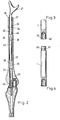
- a prosthesis designed in this way as a push-through prosthesis 34.
- This serves to be inserted through a defective bone 33.
- the defect on this bone 33 is so extensive in such cases that it is not possible to attach endoprostheses to its two ends 35, 36.
- the defective bone 33 is unable to transmit the forces introduced into it by the prosthesis without being further destroyed.
- a hole 37 extending through it in the longitudinal direction is drilled therein.
- the width of this hole 37 is to be determined so that the push-through prosthesis 34 with its plug connections can be inserted into the hole 37.
- the plug connections 38, 39 with sleeves 40, 41 which are pushed over the respective ends of the mutually adjacent parts 42, 43, 44. These sleeves are connected with locking pins 45 to the parts 42, 43, 44 projecting into them.
- the defective bone 33 is a femur, it can be provided with a rotary knee joint 46 at its lower end 36, while a saddle prosthesis 47 is provided at its upper end 35, which connects directly to that adjacent to the upper end 35 Pelvic bone allows.
- the push-through prosthesis 34 must be better adapted to the individual circumstances of the patient, it is conceivable to also use intermediate pieces 34 in the context of the push-through prosthesis, which serve to compensate for differences in length.
- a further adaptation of the push-through prosthesis 34 to the individual circumstances of the patient is possible in that the connecting parts 2, 3 are set proximally and distally on the central part in certain angular positions relative to one another and can be fixed in these angular positions.
- a serration 52 can be provided, which should have a module that is as small as possible.
- While the toothing of one of the two parts 18 to be connected to one another is provided in the region of its end 4 facing a connecting part 2 on a cylindrical projection 57 rising in the center of this end 4, a central bore 58 provided at a corresponding point is provided in the adjacent connecting part 2, into which the protrusion 57 protrudes.
- the projection 57 is provided on its cylindrical outer surface with a toothing 52 which corresponds to a toothing which rises on the cylindrical inner surfaces of the central bore 58.
- the modules of the toothing 53 are selected so that the two toothings can be guided into one another when the connecting part 2 is plugged onto the part 18.
- an angular position of the connecting part 2 relative to the part 18 can be selected. In this angular position, the toothings 52 snap into one another, so that the connecting part 2 cannot be rotated relative to the part 18.
- a similar adjustment possibility is possible in that the parts 2, 3; 18, '19, 20; 42, 43, 44 are connected to one another via conical connection points.
- It can for example, on the end 5 of a part 20 there is an outer cone 54 which corresponds in terms of the angular position of its conical surfaces to an inner cone 55 which is introduced into the adjacent end of a connecting part 3.
- the cone surfaces of the outer cone 54 are pressed onto those of the inner cone 55 with the aid of a clamping screw 56 which extends in the longitudinal direction through the part 20 and cooperates with an internal thread provided in the connecting part 3.
- this clamping screw 56 which is freely rotatable in part 20, the conical surfaces are pressed so tightly against one another that twisting of the two parts 20, 3 relative to one another is not possible.
- the individual parts 18, 19, 20; 42, 43, 44 to be connected to one another via screw connections 48, 49.
- two rod parts 1 are screwed together; while one rod part has an internal thread 50 at one end, the rod part adjacent to it is provided with an external thread 51 with its end facing it.
- the length of the two threads 50, 51 is such that the external thread 51 completely disappears in the internal thread when the two parts of the rod part 1 are screwed together.
- the two threads 50, 51 can be designed as a fine thread, which shows a self-locking effect when the two parts are firmly screwed together. In addition, however, it can also be secured against rotation, for example with additional locking pins.
- the endoprosthesis is expediently manufactured and supplied in the form of kits. These kits contain all the individual parts requested by the user. In addition, compensating pieces are provided in the kit, the length of which is based on the usual dimensional tolerances. These compensating pieces can be used by the surgeon depending on the individual circumstances that he finds in the patient.
- the endoprosthesis can be used in all cases in which rod-shaped bones have defects.
- a push-through prosthesis 34 it can be used in particular for long bones. It can therefore also be used in the area of the arm bones; as a push-through prosthesis for an upper arm bone, it is provided on the one hand with a shoulder joint and on the other hand with an elbow joint.
- the connecting parts 2, 3 can be used as part of the kit to be used as a push-through prosthesis 34 already be prefabricated. It is molich that the distal connector 3 can be prefabricated as a simultaneous replacement of the condyles. In this way, parts 18, 19, 20; 42, 43, 44 a knee joint endoprosthesis, of whatever type, or else a knee joint endoprosthesis with condyle replacement, of whatever type (rotary or hinge endoprosthesis) are mounted.
- the distal connecting part 3, namely the hinge or rotary endoprosthesis is optionally mounted with a condyle replacement that can possibly be pushed on, that a patellar plain bearing can also be used if necessary, and that finally both the condyles and the patellar one Plain bearings can be replaced.
- the surgeon receives an optimal kit system, which brings considerable cost savings in both assembly and manufacture.
- Metal is essentially considered as the material for the manufacture of the prosthesis.
- a cobalt-chromium-molybdenum alloy which is known in the field of medical technology as a vitalium, is particularly worth considering.
- the parts can also be made from a titanium alloy.
- the head 11 of a hip joint will be made of ceramic, while the pan 10 or other plain bearings are made of polyethylene.
Abstract
Eine Endoprothese zum Ersatz stabförmiger Knochen besteht mindestens aus einem Anschlußteil (2, 3) und einem Stabteil (1). Mindestens einer dieser beiden Teile ist im Sinn der Anpassung an individuelle Verhältnisse veränderlich gestaltet. Der Stabteil (1) kann aus einer Anzahl von stabförmigen Teilen (42, 43, 44) bestehen, die an ihren jeweiligen Verbindungsstellen Kupplungen aufweisen. Eine Kupplung kann als Hülse (40, 41) ausgebildet sein, in die ein Stift (45) des benachbarten Teils hineinragt. Dieser Stift ist am Ende dieses Nachbarteils ausgebildet und in der Hülse befestigt. Der Anschlußteil kann als ein Lager ausgebildet sein, über das der Stabteil mit einem benachbarten Knochen verbunden ist. Für dieses Lager kommen die im menschlichen Körper vorhandenen Gelenke in Betracht. Die eine Endoprothese bildenden Teile können als vorgefertigte Einheiten ausgebildet sein, die zum Zwecke des vorteilhaften Einbaus in einzelne Teile zerlegt werden können.An endoprosthesis for the replacement of rod-shaped bones consists of at least one connecting part (2, 3) and one rod part (1). At least one of these two parts is designed to be adaptable to individual circumstances. The rod part (1) can consist of a number of rod-shaped parts (42, 43, 44) which have couplings at their respective connection points. A coupling can be designed as a sleeve (40, 41) into which a pin (45) of the adjacent part projects. This pin is formed at the end of this neighboring part and fastened in the sleeve. The connecting part can be designed as a bearing via which the rod part is connected to an adjacent bone. The joints present in the human body come into consideration for this camp. The parts forming an endoprosthesis can be designed as prefabricated units which can be disassembled into individual parts for the purpose of advantageous installation.
Description
Die Erfindung betrifft eine Endoprothese zum Ersatz stabförmiger Knochen mit mindestens je einem Anschlußteil und einem Stabteil.The invention relates to an endoprosthesis for the replacement of rod-shaped bones with at least one connecting part and one rod part.
Derartige Endoprothesen haben sich in der Praxis einen festen Platz für die Versorgung von Kranken gesichert, bei denen Knochendefekte im Regelfall nur an einem Ende eines stabförmigen Knochens auftreten. Der Einbau derartiger Endoprothesen mit Rücksicht auf die individuellen Erfordernisse eines bestimmten Patienten ist dädurch möglich, daß zum Ausgleich von Längenunterschieden die entsprechende Endoprothese mehr oder minder weit in den zu versorgenden Knochen eingesetzt wird.In practice, endoprostheses of this type have secured a permanent place for the care of patients in whom bone defects usually only occur at one end of a rod-shaped bone. The installation of such endoprostheses with regard to the individual requirements of a particular patient is possible by the fact that the corresponding endoprosthesis is inserted more or less far into the bone to be treated to compensate for differences in length.
Darüber hinaus werden aber auch Endoprothesen in den Fällen verwendet, in denen ein ganzer stabförmiger Knochen ersetzt werden muß. Beispielsweise sind Operationstechniken bekannt, bei denen ein totaler Femur durch eine Endoprothese ersetzt wird. In diesen Fällen besitzt der Stabteil an seinen beiden Enden je ein Anschlußteil. Die Länge der Endoprothese muß so bestimmt werden, daß die beiden Anschlußteile den individuellen Bedürfnissen eines Patienten entsprechend eingebaut werden können, ohne daß Längenverschiebungen ungewollt auftreten. Derartige Längenverschiebungen führen im Regelfall dazu, daß der mit einer solchen Endoprothese versorgte Patient körperliche Schwierigkeiten in Kauf nehmen muß. Beispielsweise kann ein nicht richtig bemessener Ersatz für einen Femur dazu führen, daß das auf diese Weise versorgte Bein eines Patienten länger ist als das andere. Ferner bereitet die präoperative Vermessung der Längen, die herzustellen sind, mitunter Schwierigkeiten, so daß Fehler nicht immer ausgeschlossen werden können. Dies kann im Extremfall zur Unmöglichkeit des Einbaus in der operativen Situation führen.In addition, endoprostheses are also used in cases where a whole rod-shaped bone has to be replaced. For example, surgical techniques are known in which a total femur is replaced by an endoprosthesis. In these cases, the rod part has a connecting part at both ends. The length of the endoprosthesis must be determined in such a way that the two connecting parts can be installed according to the individual needs of a patient, without length changes occurring unintentionally. Such shifts in length generally lead to the fact that the patient supplied with such an endoprosthesis has to accept physical difficulties. For example, an incorrectly dimensioned replacement for a femur can result in the leg being treated in this way Patient is longer than the other. Furthermore, the preoperative measurement of the lengths to be produced can be difficult, so that errors cannot always be excluded. In extreme cases, this can lead to the impossibility of installation in the operative situation.
Aufgabe der vorliegenden Erfindung ist es daher, die Endoprothese der einleitend genannten Art so zu verbessern, daß Schwierigkeiten beim Einbau der Endoprothese verhindert werden, die durch eine nicht ausreichende Bemessung der Prothese entstehen können. Darüber hinaus kann sich intraoperativ die Situation ergeben, daß das vorgefertigte, geplante Anschlußteil nicht implantierbar ist und ein anderes gewünscht wird.The object of the present invention is therefore to improve the endoprosthesis of the type mentioned in the introduction in such a way that difficulties in installing the endoprosthesis are prevented which can arise from an insufficient dimensioning of the prosthesis. In addition, the situation may arise intraoperatively that the prefabricated, planned connecting part cannot be implanted and another is desired.
Diese Aufgabe wird erfindungsgemäß dadurch gelöst, daß mindestens eines der Teile im Sinne der Anpassung an individuelle Verhältnisse veränderlich gestaltet ist.This object is achieved in that at least one of the parts is designed to be adaptable to individual circumstances.
Durch diese Anpaßbarkeit mindestens eines der Teile ist es möglich, noch während der Operation die gesamte Endoprothese so zu wählen, daß sie den individuellen Bedürfnissen ihres Trägers exakt Rechnung tragen kann. Eine derartige Anpassung kann vor Beginn der Operation durch eine entsprechende Operationsplanung außerordentlich schwierig sein, da die für die Bemessung der Endoprothese notwendigen röntgenologischen Aufnahmen den Abstand relativ ungenau wiedergeben. Die erfindungsgemäßeEnäoprothese kann noch während der Operation den jeweiligen Verhältnissen genau angepaßt werden, ohne daß die Operationszeit dadurch wesentlich verlängert wird. Durch eine entsprechende Bemessung und Auswahl der Form sowohl der Anschlußteile als auch des Stabteils ist eine Feinanpassung hinsichtlich der benötigten Längen und der Lage möglich, in der die Endoprothese nach ihrem Einbau verlaufen soll. Ferner können die notwendigen Anschlußteile variiert werden.This adaptability of at least one of the parts makes it possible to select the entire endoprosthesis during the operation in such a way that it can take the individual needs of its wearer exactly into account. Such an adjustment can be extremely difficult before the start of the operation by planning the operation accordingly, since the radiographic recordings necessary for dimensioning the endoprosthesis reflect the distance relatively imprecisely. The endoprosthesis according to the invention can still be adapted precisely to the prevailing conditions during the operation, without the operation time being thereby extended significantly. By appropriate dimensioning and selection of the shape of both the connecting parts and the rod part, a fine adjustment with regard to the required lengths and the position in which the endoprosthesis is to run after its installation is possible. Furthermore, the necessary connecting parts can be varied.
Schwierig ist insbesondere die Versorgung solcher Knochen, die sowohl proximal als auch distal Defekte aufweisen. Das zwischen den Defekten liegende Knochenstück ist häufig so kurz, daß Endoprothesen an ihm nicht mehr befestigt werden können. Bisher war es notwendig, den Restknochen durch eine vollständige Endoprothese zu ersetzen.It is particularly difficult to care for bones that have defects both proximally and distally. The piece of bone lying between the defects is often so short that endoprostheses can no longer be attached to it. Previously, it was necessary to replace the residual bone with a complete endoprosthesis.
Aufgabe der vorliegenden Erfindung ist es daher weiterhin, die einleitend genannte Endoprothese so zu verbessern, daß auch kurze Reststücke von Röhrenknochen erhalten werden können, wenn sowohl proximale als auch distale Defekte die Montage einer Totalendoprothese erforderlich machen.It is therefore an object of the present invention to improve the endoprosthesis mentioned in the introduction in such a way that even short remnants of long bones can be obtained if both proximal and distal defects necessitate the installation of a total endoprosthesis.
Diese Aufgabe wird erfindungsgemäß durch eine bevorzugte Ausführungsform der Erfindung gelöst, bei der der Stabteil aus einer Anzahl von stabförmigen Einzelstücken besteht, die an ihren jeweiligen Verbindungsstellen Kupplungen aufweisen.This object is achieved according to the invention by a preferred embodiment of the invention, in which the rod part consists of a number of rod-shaped individual pieces which have couplings at their respective connection points.
Diese Einzelstücke können vom Chirurgen so ausgewählt werden, daß die Verbindungsstellen an einer Stelle liegen, die für die Durchführung der Operation besonders günstig ist. Beispielsweise ist es denkbar, bei einem großen Defekt eines Röhrenknochens die Endoprothese mit ihrem Stabteil durch diesen hindurchzustecken und anschließend die beiden Anschlußteile mit dem Stabteil zu verbinden. In diesem Falle wird der Stabteil zweckmäßigerweise so ausgeführt, daß er innerhalb des Röhrenknochens einteilig verläuft, so daß Kupplungen zum Verbinden mit anderen Stabteilen bzw. den Anschlußteilen lediglich außerhalb des Röhrenknochens vorhanden sind.These individual pieces can be selected by the surgeon in such a way that the connection points lie at a point which is necessary for the implementation of the Operation is particularly cheap. For example, in the event of a major defect in a tubular bone, it is conceivable to insert the endoprosthesis with its rod part through it and then to connect the two connecting parts to the rod part. In this case, the rod part is expediently designed so that it runs in one piece within the tubular bone, so that couplings for connecting to other rod parts or the connecting parts are only present outside the tubular bone.
Auf diese Weise wird der Röhrenknochen einerseits mit einer inneren Schienung versehen und andererseits können die von dem Röhrenknochen zu übertragenden Kräfte nunmehr problemlos durch die Endoprothese übertragen werden. Diese Operationstechnik hat insbesondere dann Vorteile, wenn der Rest des Röhrenknochens aus biomechanischen Gründen nicht mehr ausreicht, um in ihm beidseitig Teilendoprothesen zu befestigen, die den Anschluß zu dem benachbarten Knochen herstellen können. Beispielsweise ist es denkbar, durch die gesunden Teile eines Femurs eine totale Femur-Endoprothese hindurchzuführen, die einerseits mit einem Hüftgelenk und andererseits mit einem Kniegelenk verbunden ist.In this way, the tubular bone is provided with an internal splint on the one hand, and on the other hand, the forces to be transmitted from the tubular bone can now be easily transmitted through the endoprosthesis. This surgical technique is particularly advantageous when the rest of the tubular bone is no longer sufficient for biomechanical reasons to attach partial endoprostheses on both sides that can establish the connection to the adjacent bone. For example, it is conceivable to pass a total femoral endoprosthesis through the healthy parts of a femur, which is connected on the one hand to a hip joint and on the other hand to a knee joint.
Durch diese Ausbildung einer Durchsteckprothese wird soviel wie möglich erhaltenswerter Knochen belassen, sofern dieser nicht durch Infektionen, Trauma, Tumor usw. zerstört ist. Auf diese Weise wird das Implantat so weit wie möglich knöchern gedeckt. Die erhaltenswerten Knochen bieten Ansatz für Sehnen und Muskeln. Soweit die Knochenteile erhaltenswerte Gelenkteile aufweisen, können diese weiterhin zur Ausführung ihrer Funktionen herangezogen werden. Insbesondere erweist es sich als zweckmäßig, das patellare Gleitlager zu erhalten, wenn beispielsweise das Femur durch eine Durchsteckprothese ersetzt wird.This design of a push-through prosthesis leaves as much bone that is worth preserving as long as it is not destroyed by infections, trauma, tumor, etc. In this way, the implant is covered as much as possible. The bones that are worth preserving offer an approach for tendons and muscles. So much for the bones parts that are worth preserving, they can still be used to perform their functions. In particular, it proves to be expedient to maintain the patellar slide bearing if, for example, the femur is replaced by a push-through prosthesis.
Diese Durchsteckprothese kann den individuellen Bedürfnissen genau angepaßt werden, da die für den Anschluß des Femurs notwendigen Anschlußteile sowohl proximal als auch distal bezüglich des Mittelteils in bestimmten Winkelstellungen zueinander eingerichtet und fixiert werden können. Diese Anpaßbarkeit ist im Hinblick auf individuelle Unterschiede, die von Fall zu Fall auftreten können, von erheblicher Wichtigkeit. Ferner können Individuell notwendige Anschlußteile aufgesetzt werden, im Falle eines Femurs proximal ein Kopfabschluß oder eine Sattelprothese, distal ein Scharnierknie oder ein Rotationsknie.This push-through prosthesis can be adapted precisely to individual needs, since the connection parts necessary for the connection of the femur can be set up and fixed both proximally and distally with respect to the central part in certain angular positions. This adaptability is of considerable importance with regard to individual differences that can occur from case to case. Furthermore, individually necessary connection parts can be put on, in the case of a femur proximally a head end or a saddle prosthesis, distally a hinge knee or a rotating knee.
Weitere Einzelheiten der Erfindung ergeben sich aus der nachfolgenden ausführlichen Beschreibung und den beigefügten Zeichnungen, in denen eine bevorzugte Ausführungsform der Erfindung beispielsweise veranschaulicht ist.Further details of the invention will become apparent from the following detailed description and the accompanying drawings, in which a preferred embodiment of the invention is illustrated, for example.
In den Zeichnungen zeigen:
- Fig. 1 ; Eine Ansicht eines zusammengesetzten Bausatzes einer Endoprothese,
- Fig. 2 ; eine Ansicht einer in einen Knochen eingesetzten Endoprothese aus mehreren Bauteilen,
- Fig. 3 ; einen Schnitt durch einen Stabteil einer Endoprothese mit Gewindeanschluß,
- Fig. 4 : einen Längsschnitt durch einen Zwischenteil einer Endoprothese mit Gewindeanschlüssen,
- Fig. 5 : eine teilweise geschnittene Längsdarstellung einer konischen Verbindungsstelle,
- Fig. 6 : eine teilweise geschnittene Längsdarstellung einer mit einer Zähnelung versehenen Verbindung und
- Fig. 7: einen Querschnitt entlang der Schnittlinie VII-VII in Figur 6.
- Fig. 1; A view of an assembled kit of an endoprosthesis,
- Fig. 2; 1 shows a view of an endoprosthesis inserted into a bone from several components,
- Fig. 3; a section through a rod part an endoprosthesis with threaded connection,
- 4: a longitudinal section through an intermediate part of an endoprosthesis with threaded connections,
- 5: a partially sectioned longitudinal representation of a conical connection point,
- 6 shows a partially sectioned longitudinal illustration of a connection provided with a toothing and
- 7 shows a cross section along the section line VII-VII in FIG. 6.
Eine Endoprothese besteht im wesentlichen aus einem Stabteil 1-und zwei Anschlußteilen 2, 3. Die Anschlußteile 2, 3 sind an zwei einander sich gegenüberliegenden Enden 4, 5 des Stabteils 1 befestigt. Die Anschlußteile 2, 3 sind als Lager-6, 7 ausgebildet, über die der Stabteil 1 mit benachbarten Knochen 8, 9 schwenkbar in Verbindung steht. Das am oberen Ende 4 ausgebildete Lager 6 ist als ein im Beckenknochen 8 ausgebildetes Hüftgelenk ausgebildet, dessen Pfanne 10 im Knochen 8 befestigt ist. In diese Pfanne 10 faßt ein Kopf 11 des Hüftgelenkes formschlüssig hinein, der mit dem Anschlußteil 2 fest verbunden ist.An endoprosthesis essentially consists of a
Im Bereich des unteren Endes 5 ist das Lager 7 als ein Scharnier ausgebildet, dessen beiden Seitenteile 12, 13 im Anschluß 3 ausgebildet sind. Zwischen diesen beiden Seitenteilen 12, 13 ist ein Schlitz 14 ausgebildet, in dem ein Mittelteil 15 schwenkbar um eine nicht dargestellte Achse gelagert ist, die in den Seitenteilen 12, 13 befestigt ist. An das Mittelteil 15 schließt sich in Richtung auf den Unterschenkelknochen 9 über einen Teller 16 ein Schaft 17 an, der im Knochen 9 befestigt ist.In the area of the
Der Stabteil 1 ersetzt einen Oberschenkelknochen. Er ist aus mehreren Teilen 18, 19, 20 zusammengesetzt, die von verschiedener Länge sind. Diese Teile 18, 19, 20 sind untereinander und mit den Anschlußteilen 2, 3 über Steckverbindungen 21, 22, 23, 24 verbunden. Im Bereich dieser Steckverbindungen 21, 22, 23, 24 ist eines der beiden zu verbindenden Teile mit einem hülsenartigen Loch versehen, in das der andere Teil mit einem an seinem Ende vorgesehenenSchaft hineinragt. Um ein Verdrehen der einzelnen Teile 18, 19, 20 gegeneinander und gegenüber den Anschlußteilen 2, 3 zu verhindern, werden die Steckverbindungen jeweils mit Sicherungsstiften 25, 26, 27, 28 gesichert. Diese ragen durch entsprechende Sicherungslöcher hindurch, die im Bereich der Steckverbindungen 21, 22, 23, 24 durch die einzelnen Teile 18, 19, 20 hindurchgebohrt sind. Bei der Bemessung der Sicherungsstifte 25, 26, 27, 28 ist darauf zu achten, daß diese in ihrer Länge dem Durchmesser des Stabteiles 1 angepaßt sind, um zu verhindern, daß sie im eingebauten Zustand aus den sie aufnehmenden Löchern einseitig oder beidseitig herausragen.The
Es ist auch möglich, die Steckverbindungen 21, 22, 23, 24 in der Weise herzustellen, daß sämtliche Teile 18, 19, 20 und die Anschlußteile 2, 3 an den einander zugewandten Enden mit hülsenartigen Bohrungen versehen werden. In diesem Falle werden in die entsprechenden Bohrungen lose Stifte hineingesteckt, die allerdings in den beiden sich gegenüber liegenden Enden der Teile 18, 19, 20 bzw. der Anschlußteile 2, 3 durch entsprechende Sicherungsstifte 29, 30, 31, 32 zusätzlich gesichert werden müssen. Diese Ausführungsform hat den Vorteil, daß die Anzahl der Kombinationsmöglichkeiten der Teile 18, 19, 20 vergrößert wird.It is also possible to produce the
Es ist auch denkbar, aufgrund einer Operationsplanung mindestens einige der miteinander zu verbindenden Teile 18, 19', 20 so vorzufertigen, daß sie während der Operation nur noch zusammengesteckt werden brauchen. In manchen Fällen wird aber eine derartige Operationsplanung nicht möglich sein, so daß mit Hilfe von kurzen Teilen 20 noch während der Operation ein Längenausgleich vorgenommen werden muß, falls sich dieserals notwendig erweisen sollte.It is also conceivable, on the basis of operation planning, to prefabricate at least some of the
Es ist auch möglich, eine in dieser Weise konzipierte Prothese als Durchsteckprothese 34 zu konzipieren. Diese dient dazu, durch einen defekten Knochen 33 hindurchgesteckt zu werden. Der Defekt an diesem Knochen 33 ist in solchen Fällen derartig umfangreich, daß eine Befestigung von Endoprothesen an seinen beiden Enden 35, 36 nicht möglich ist. Der defekte Knochen 33 ist nicht in der Lage, die von den Prothesen in ihn eingeleiteten Kräfte zu übertragen, ohne dabei weiter zerstört zu werden.It is also possible to design a prosthesis designed in this way as a push-through
Zum Zwecke der Befestigung einer Durchsteckprothese 34 durch einen Knochen 33 wird in diesen ein sich in Längsrichtung durch ihn erstreckendes Loch 37 gebohrt. Die Weite dieses Loches 37 ist so zu bestimmen, daß die Durchsteckprothese 34 mit ihren Steckverbindungen in das Loch 37 eingeführt werden kann. Dabei ist es denkbar, die Steckverbindungen 38, 39 mit Hülsen 40, 41 vorzunehmen, die über die jeweiligen Enden der einander benachbarten Teile 42, 43, 44 passend geschoben werden. Diese Hülsen werden mit Sicherungsstiften 45 mit den jeweils in sie hineinragenden Teilen 42, 43, 44 verbunden.For the purpose of fastening a push-through
Falls es sich bei dem defekten Knochen 33 um einen Oberschenkelknochen handelt, kann dieser an seinem unteren Ende 36 mit einem Rotationskniegelenk 46 versehen sein, während an seinem oberen Ende 35 eine Sattelprothese 47 vorgesehen ist, die eine unmittelbare Verbindung mit dem dem oberen Ende 35 benachbarten Beckenknochen ermöglicht.If the
Auch bei dieser Durchsteckprothese 34 können wesentliche Teile bereits vor Beginn der Operation vorgefertigt und miteinander verbunden werden.With this push-through
Falls sich beim Einbau der Durchsteckprothese 34 in den Knochen 33 herausstellen sollte, daß die Durchsteckprothese 34 den individuellen Verhältnissen des Patienten besser angepaßt werden muß, ist es denkbar, auch im Rahmen der Durchsteckprothese 34 Zwischenstücke zu verwenden, die einem Ausgleich von Längendifferenzen dienen. Eine weitere Anpassung der Durchsteckprothese 34 an die individuellen Verhältnisse des Patienten ist dadurch möglich, daß die Anschlußteile 2, 3 proximal und distal am Mittelteil in bestimmten Winkelstellungen zueinander eingerichtet werden und in diesen Winkelstellungen fixierbar sind. Zu diesem Zwecke kann eine Zähnelung 52 vorgesehen sein, die einen möglichst kleinen Modul aufweisen sollte. Während die Zähnelung eines der beiden aneinander anzuschließenden Teile 18 im Bereich seines einem Anschlußteil 2 zugewandten Endes 4 auf einem sich im Zentrum dieses Endes 4 erhebenden zylinderartigen Vorsprung 57 vorgesehen ist, ist im benachbarten Anschlußteil 2 eine an entsprechender Stelle vorgesehene Mittelbohrung 58 vorgesehen, in die der Vorsprung 57 hineinragt. Der Vorsprung 57 ist an seiner zylindrischen Außenfläche mit einer Zähnelung 52 versehen, der eine Zähnelung entspricht, die sich auf den zylindrischen Innenflächen der Mittelbohrung 58 erhebt. Die Module der Zähnelung 53 sind so gewählt, daß die beiden Zähnelungen ineinander geführt werden können, wenn das Anschlußteil 2 auf das Teil 18 aufgesteckt wird. Je nach den beim Patienten vorgefundenen anatomischen Verhältnissen kann eine Winkelstellung des Anschlußteils 2 gegenüber dem Teil 18 gewählt werden. In dieser Winkelstellung rasten die Zähnelungen 52 ineinander ein, so daß das Anschlußteil 2 gegenüber dem Teil 18 nicht verdrehbar ist.If it should turn out during the installation of the push-through
Eine ähnliche Justiermöglichkeit ist dadurch möglich, daß die miteinander zu verbindenden Teile 2, 3; 18,' 19, 20; 42, 43, 44 über konische Verbindungsstellen miteinander verbunden werden. Dabei kann sich beispielsweise auf dem Ende 5 eines Teiles 20 ein Außenkonus 54 erheben, der hinsichtlich der Winkelstellung seiner Konusflächen mit einem Innenkonus 55 übereinstimmt, der in das benachbarte Ende eines Anschlußteiles 3 eingebracht ist. Die Konusflächen des Außenkonus 54 werden auf die des Innenkonus 55 mit Hilfe einer Spannschraube 56 gedrückt, die sich in Längsrichtung durch das Teil 20 erstreckt und mit einem im Anschlußteil 3 vorgesehenen Innengewinde zusammenarbeitet. Mit Hilfe dieser Spannschraube 56, die im Teil 20 frei drehbar ist, werden die Konusflächen so fest aufeinander gepreßt, daß eine Verdrehung der beiden Teile 20, 3 gegeneinander nicht möglich ist.A similar adjustment possibility is possible in that the
Das Teil 20 kann seinerseits gegenüber dem benachbarten Teil 19 über eine Konusverbindung verbunden sein. In diesem Falle stützt sich die Spannschraube 56 mit ihrem Kopf 59 auf dem Boden 60 eines nicht dargestellten Innenkonus ab, mit dem ein entsprechender Außenkonus des benachbarten Teiles 19 zusammenarbeitet. Darüber hinaus ist es aber auch denkbar, die Teile 19, 20 auf andere Weise miteinander zu verbinden, beispielsweise durch Sicherungsstifte 29, 30, 31, 32. Mit Hilfe der Konen 53, 54 ist eine stufenlose Anpaßbarkeit der Winkelstellung an die jeweils aufgefundenen anatomischen Verhältnisse eines Patienten möglich. Knochenteile müssen nicht deswegen entfernt werden, damit die Durchsteckprothese 34 in den jeweiligen Knochenbau des Patienten eingefügt werden kann. Auf diese Weise wird ein Maximum erhaltenswerter Knochen belassen, sofern dieser nicht durch Infektion, Trauma, Tumor usw. zerstört ist. Die Erhaltung des Knochens ist wichtig, um
- 1. das Implantat knöchern zu decken,
- 2. einen Ansatz für Sehnen und Muskeln zu bieten und
- 3. falls der erhaltene Knochen erhaltenswerte Gelenkteile beinhaltet, diese weiterhin so weit wie möglich zu nutzen.
- 1. to cover the implant bones,
- 2. to offer an approach to tendons and muscles and
- 3. If the bone obtained contains joint parts worth preserving, continue to use them as far as possible.
Schließlich ist es denkbar, die einzelnen Teile 18, 19, 20; 42, 43, 44 über Schraubverbindungen 48, 49 miteinander zu verbinden. In diesem Falle werden zwei Stabteile 1 zusammengeschraubt; während der eine Stabteil an seinem einen Ende ein Innengewinde 50 aufweist, ist der ihm benachbarte Stabteil mit seinem ihn zugewandten Ende mit einem Außengewinde 51 versehen. Die beiden Gewinde 50, 51 sind hinsichtlich ihrer Länge so eingerichtet, daß das Außengewinde 51 vollkommen im Innengewinde verschwindet, wenn die beiden Teile des Stabteils 1 fest miteinander verschraubt sind. Gleichzeitig können die beiden Gewinde 50, 51 als Feingewinde ausgeführt werden, das eine selbsthemmende Wirkung zeigt, wenn die beiden Teile fest miteinander verschraubt werden. Darüber hinaus kann aber auch noch eine Sicherung gegen Verdrehen beispielsweise mit zusätzlichen Sicherungsstiften vorgenommen werden.Finally, it is conceivable for the
Schließlich ist es denkbar, eine Verbindung zwischen den Teilen 18, 19, 20; 42, 43, 44 dadurch herbeizuführen, daß die jeweils benachbarten Teile miteinander verklebt werden. Außerdem ist daran zu denken, daß an den jeweiligen Verbindungsstellen eine gegen Verdrehung sichere Verbindung dadurch zustande kommt, daß die einander benachbarten Teile durch Ultraschall miteinander verbunden werden.Finally, it is conceivable to establish a connection between the
Um einen gleichmäßigen Längenausgleich herbeiführen zu können, ist es darüber hinaus denkbar, die einzelnen Teile 18, 19, 20; 42, 43, 44 einzeln oder in ihrer Gesamtheit als Teleskopteile auszubilden. Diese können je nach Bedarf weiter oder weniger weit auseinander gezogen und anschließend durch geeignete Maßnahmen beispielsweise Sicherungsstifte gegen Verschieben gesichert werden.In order to be able to achieve a uniform length compensation, it is also conceivable for the
Zweckmäßigerweise wird die Endoprothese in Form von Bausätzen hergestellt und geliefert. Diese Bausätze enthalten sämtliche vom Anwender gewünschten Einzelteile. Darüber hinaus sind in dem Bausatz Ausgleichsstücke vorgesehen, deren Länge auf übliche Maßtoleranzen abgestellt sind. Diese Ausgleichsstücke können vom Chirurgen je nach den individuellen Verhältnissen, die er beim Patienten vorfindet, angewendet werden.The endoprosthesis is expediently manufactured and supplied in the form of kits. These kits contain all the individual parts requested by the user. In addition, compensating pieces are provided in the kit, the length of which is based on the usual dimensional tolerances. These compensating pieces can be used by the surgeon depending on the individual circumstances that he finds in the patient.
Die Endoprothese ist in allen Fällen einsetzbar, in denen stabförmige Knochen Defekte aufweisen. In ihrer Version als Durchsteckprothese 34 ist sie insbesondere für Röhrenknochen anwendbar. Sie kann daher auch im Bereich der Armknochen Verwendung finden; als Durchsteckprothese für einen Oberarmknochen ist sie einerseits mit einem Schultergelenk und andererseits mit einem Ellenbogengelenk versehen.The endoprosthesis can be used in all cases in which rod-shaped bones have defects. In its version as a push-through
Die Anschlußteile 2, 3 können im Rahmen des als Durchsteckprothese 34 zu verwendenden Bausatzes bereits vorgefertigt sein. Dabei ist es molich, daß das distale Anschlußteil 3 vorgefertigt als gleichzeitiger Ersatz der Condylen montierbar ist. Auf diese Weise kann wahlweise mit den Teilen 18, 19, 20; 42, 43, 44 eine Kniegelenk-Endoprothese, welcher Art auch immer, oder aber eine Kniegelenk-Endoprothese mit Condylenersatz, welcher Art auch immer (Rotations- oder Scharnier-Endoprothese) montiert werden. Es ist jedoch auch möglich, daß das distale Anschlußteil 3, nämlich die Scharnier- oder Rotations-Endoprothese wahlweise mit einem möglicherweise aufschiebbaren Condylenersatz montiert wird, daß ferner im Bedarfsfalle ein patellares Gleitlager eingesetzt werden kann, und daß schließlich sowohl die Condylen als auch das patellare Gleitlager ersetzt werden können. Auf diese Weise erhält der Chirurg ein optimales Bausatzsystem, das erhebliche Kosteneinsparungen sowohl bei der Montage als auch bei der Herstellung mit sich bringt. Beispielsweise ist es denkbar, eine Durchsteckprothese 34 zu fertigen, die distal das Anschlußteil 3 aufweist. Im Bedarfsfalle können dazu entweder die Condylen oder das patellare Gleitlager oder beide gemeinsam zusätzlich montiert werden.The connecting
Als Material für die Herstellung der Prothese kommt im wesentlichen Metall in Betracht. Zu denken ist insbesondere an eine Kobalt-Chrom-Molybdän-Legierung, die im Bereich der medizinischen Technik als Vitalium bekannt ist. Darüber hinaus können die Teile aber auch aus einer Titanlegierung hergestellt werden. In diesem Falle wird der Kopf 11 eines Hüftgelenkes aus Keramik gefertigt werden, während die Pfanne 10 bzw. andere Gleitlager aus Polyäthylen bestehen.Metal is essentially considered as the material for the manufacture of the prosthesis. A cobalt-chromium-molybdenum alloy, which is known in the field of medical technology as a vitalium, is particularly worth considering. In addition, the parts can also be made from a titanium alloy. In this case, the
Claims (39)
Applications Claiming Priority (2)
| Application Number | Priority Date | Filing Date | Title |
|---|---|---|---|
| DE19813138848 DE3138848A1 (en) | 1981-09-30 | 1981-09-30 | ENDOPROTHESIS TO REPLACE ROD-SHAPED BONES |
| DE3138848 | 1981-09-30 |
Publications (2)
| Publication Number | Publication Date |
|---|---|
| EP0079441A1 true EP0079441A1 (en) | 1983-05-25 |
| EP0079441B1 EP0079441B1 (en) | 1988-05-04 |
Family
ID=6143007
Family Applications (1)
| Application Number | Title | Priority Date | Filing Date |
|---|---|---|---|
| EP82108411A Expired EP0079441B1 (en) | 1981-09-30 | 1982-09-11 | Endoprosthesis for replacement of rod-shaped bones |
Country Status (3)
| Country | Link |
|---|---|
| US (1) | US5026399A (en) |
| EP (1) | EP0079441B1 (en) |
| DE (1) | DE3138848A1 (en) |
Cited By (4)
| Publication number | Priority date | Publication date | Assignee | Title |
|---|---|---|---|---|
| EP0144667A1 (en) * | 1983-10-27 | 1985-06-19 | Wright Manufacturing Company | Adjustable length prosthetic joint implant |
| EP0163121A1 (en) * | 1984-05-11 | 1985-12-04 | Waldemar Link (GmbH & Co.) | Arrangement for producing an endoprosthesis anatomically made to measure |
| EP0228511A2 (en) * | 1985-10-02 | 1987-07-15 | GMT Gesellschaft für medizinische Technik mbH | Saddle-shaped prosthesis |
| EP0300131A2 (en) * | 1987-03-27 | 1989-01-25 | GMT Gesellschaft für medizinische Technik mbH | Saddle prosthesis |
Families Citing this family (29)
| Publication number | Priority date | Publication date | Assignee | Title |
|---|---|---|---|---|
| DE3205577C2 (en) * | 1981-02-23 | 1989-11-02 | Inc. Zweigniederlassung Kiel 2314 Schönkirchen Howmedica International | Endoprosthesis for femoral or tibial articular bone parts and adjacent femoral or tibial bone sections |
| DE3336004C2 (en) * | 1983-10-04 | 1986-10-16 | S + G Implants GmbH, 2400 Lübeck | Adapter for a bone endoprosthesis |
| DE3340767A1 (en) * | 1983-11-08 | 1985-05-15 | Mecron Medizinische Produkte Gmbh, 1000 Berlin | KIT FOR A RESECTION PROSTHESIS |
| DE8337293U1 (en) * | 1983-12-24 | 1985-07-04 | orthoplant Endoprothetik GmbH, 2800 Bremen | Prosthetic adapter for a bone |
| FR2580171B1 (en) * | 1985-04-10 | 1989-12-01 | Rambert Andre | FEMALE PROSTHESIS FOR HIP JOINT |
| CH668703A5 (en) * | 1985-04-15 | 1989-01-31 | Sulzer Ag | CONNECTION OF TWO IMPLANT PARTS. |
| DE3528728A1 (en) * | 1985-08-09 | 1987-02-12 | Link Waldemar Gmbh Co | ENDOPROTHESIS TO REPLACE THE MEDIUM SECTION OF A LONG-STRETCHED BONE |
| DE3605630A1 (en) * | 1986-02-21 | 1987-09-03 | Orthoplant Endoprothetik | Endoprosthesis to replace rod-shaped bones |
| DE8611697U1 (en) * | 1986-04-25 | 1986-06-19 | Mecron Medizinische Produkte Gmbh, 1000 Berlin | Kit for a stem prosthesis |
| US5108437A (en) * | 1988-09-14 | 1992-04-28 | Pfizer Hospital Products Group, Inc. | Modular prosthesis |
| EP0532585B1 (en) * | 1990-06-01 | 2000-04-12 | Depuy Orthopaedics, Inc. | Metal/composite hybrid orthopedic implants |
| DE4039064A1 (en) * | 1990-12-07 | 1992-06-11 | Eska Medical Gmbh & Co | DEVICE FOR ADAPTING THE LENGTH OF AN ENDOPROTHESIS FOR TUBE BONES |
| US5312216A (en) * | 1991-06-28 | 1994-05-17 | Hogg John M | Artificial joint prosthesis |
| WO1993002641A1 (en) * | 1991-07-29 | 1993-02-18 | Joint Medical Products Corporation | Prosthetic joint system for bone replacement |
| US5658349A (en) * | 1991-07-29 | 1997-08-19 | Joint Medical Products Corporation | Prosthetic joint system for bone replacement |
| EP0649642B1 (en) * | 1993-10-21 | 1998-12-09 | Sulzer Orthopädie AG | Construction kit for a modular femoral head prosthesis, especially a reoperation prosthesis, and femoral head prosthesis made from such a kit |
| US5725592A (en) * | 1996-10-29 | 1998-03-10 | Hayes Medical, Inc. | Modular prosthesis having neck component connected to stem component through cavity in body component |
| US6053945A (en) * | 1997-09-25 | 2000-04-25 | Johnson & Johnson Professional, Inc. | Joint prosthesis having controlled rotation |
| US6010534A (en) * | 1997-09-25 | 2000-01-04 | Johnson & Johnson Professional, Inc. | Rotatable tibial prosthesis with keyed axial securement |
| US5951603A (en) * | 1997-09-25 | 1999-09-14 | Johnson & Johnson Professional, Inc. | Rotatable joint prosthesis with axial securement |
| DE19754079A1 (en) * | 1997-12-05 | 1999-06-10 | Gmt Medizinische Technik Gmbh | Endoprosthesis for at least partial replacement of a tibia |
| WO2000030569A1 (en) * | 1998-11-26 | 2000-06-02 | Eska Implants Gmbh & Co. | Reinforcement endoprosthesis |
| US6440171B1 (en) | 2001-02-27 | 2002-08-27 | Hammill Manuf. Co. | Double D key locking prosthesis |
| US20030204267A1 (en) * | 2002-04-30 | 2003-10-30 | Hazebrouck Stephen A. | Modular limb preservation system |
| US7033399B2 (en) * | 2003-08-22 | 2006-04-25 | Ortho Innovations, Inc. | Welded hip prosthesis |
| US7435263B2 (en) * | 2003-09-30 | 2008-10-14 | Depuy Products, Inc. | Modular long bone prosthesis for partial or total bone replacement |
| US20080140210A1 (en) * | 2006-09-01 | 2008-06-12 | Doubler Robert L | Modular shoulder prosthesis |
| US20080140211A1 (en) * | 2006-09-01 | 2008-06-12 | Doubler Robert L | Modular shoulder prosthesis with load bearing surface |
| US20110112649A1 (en) * | 2009-11-09 | 2011-05-12 | Biomet Manufacturing Corp. | Radial and ulnar replacement |
Citations (8)
| Publication number | Priority date | Publication date | Assignee | Title |
|---|---|---|---|---|
| DE2247560B1 (en) * | 1972-09-28 | 1973-10-04 | Artur Fischer | Hip joint head prosthesis |
| DE2305442A1 (en) * | 1973-02-03 | 1974-08-08 | Rosenthal Stemag Tech Keramik | IMPLANT FOR FASTENING INSIDE TUBE BONES |
| US4016874A (en) * | 1976-05-19 | 1977-04-12 | Maffei Ernest J | Three-part intramedullary bone-setting pin |
| GB1534071A (en) * | 1975-04-21 | 1978-11-29 | Bio Dynamics Inc | Bone fracture fixation and compression device |
| US4190044A (en) * | 1978-08-16 | 1980-02-26 | Wood Eugene W | Telescoping intermedullary pin |
| US4237875A (en) * | 1979-02-23 | 1980-12-09 | Towmotor Corporation | Dynamic intramedullary compression nailing |
| US4262665A (en) * | 1979-06-27 | 1981-04-21 | Roalstad W L | Intramedullary compression device |
| US4293962A (en) * | 1980-02-14 | 1981-10-13 | Zimmer Usa, Inc. | Bone plug inserting system |
Family Cites Families (14)
| Publication number | Priority date | Publication date | Assignee | Title |
|---|---|---|---|---|
| DE8016889U1 (en) * | 1980-09-18 | Waldemar Link (Gmbh & Co), 2000 Hamburg | Spacer for prosthetic vertebral body replacement | |
| DE8108959U1 (en) * | 1981-08-13 | Central'nyj naučno-issledovatel'skij institut travmatologii i ortopedii imeni N.N. Priorova, Moskva | Facility for restoring limb function | |
| US1236145A (en) * | 1916-11-04 | 1917-08-07 | Robert Lee Burns | Drill-stem and method of making the same. |
| US3067740A (en) * | 1959-09-08 | 1962-12-11 | Edward J Haboush | Hip joint prosthesis |
| US3170691A (en) * | 1962-07-23 | 1965-02-23 | Frank C Pritchard | Golf club shaft and hosel connector |
| GB1360485A (en) * | 1971-04-21 | 1974-07-17 | Helfet Arthur Jacob | Replacements for bicondylar joints in natural or artificial human limbs |
| CH568753A5 (en) * | 1973-08-31 | 1975-11-14 | Oscobal Ag | |
| DE2454181C3 (en) * | 1974-11-15 | 1980-02-21 | Rosenthal Technik Ag, 8672 Selb | Ceramic implant |
| US4051559A (en) * | 1974-12-27 | 1977-10-04 | Mahay & Cie | Total prosthesis of the hip |
| US4187559A (en) * | 1975-04-04 | 1980-02-12 | Sybron Corporation | Body joint endoprosthesis |
| DE2839093C3 (en) * | 1978-09-08 | 1981-10-01 | Reimer, Hans, Dr., 5609 Hückeswagen | Thigh part of a hip joint prosthesis |
| IE50750B1 (en) * | 1980-03-11 | 1986-07-09 | Howmedica | A set for assembly into a modular prosthesis |
| GB2070939B (en) * | 1980-03-11 | 1984-01-11 | Howmedica | Prosthetic joint |
| DE3205577C2 (en) * | 1981-02-23 | 1989-11-02 | Inc. Zweigniederlassung Kiel 2314 Schönkirchen Howmedica International | Endoprosthesis for femoral or tibial articular bone parts and adjacent femoral or tibial bone sections |
-
1981
- 1981-09-30 DE DE19813138848 patent/DE3138848A1/en active Granted
-
1982
- 1982-09-11 EP EP82108411A patent/EP0079441B1/en not_active Expired
-
1985
- 1985-08-14 US US06/766,072 patent/US5026399A/en not_active Expired - Lifetime
Patent Citations (8)
| Publication number | Priority date | Publication date | Assignee | Title |
|---|---|---|---|---|
| DE2247560B1 (en) * | 1972-09-28 | 1973-10-04 | Artur Fischer | Hip joint head prosthesis |
| DE2305442A1 (en) * | 1973-02-03 | 1974-08-08 | Rosenthal Stemag Tech Keramik | IMPLANT FOR FASTENING INSIDE TUBE BONES |
| GB1534071A (en) * | 1975-04-21 | 1978-11-29 | Bio Dynamics Inc | Bone fracture fixation and compression device |
| US4016874A (en) * | 1976-05-19 | 1977-04-12 | Maffei Ernest J | Three-part intramedullary bone-setting pin |
| US4190044A (en) * | 1978-08-16 | 1980-02-26 | Wood Eugene W | Telescoping intermedullary pin |
| US4237875A (en) * | 1979-02-23 | 1980-12-09 | Towmotor Corporation | Dynamic intramedullary compression nailing |
| US4262665A (en) * | 1979-06-27 | 1981-04-21 | Roalstad W L | Intramedullary compression device |
| US4293962A (en) * | 1980-02-14 | 1981-10-13 | Zimmer Usa, Inc. | Bone plug inserting system |
Cited By (6)
| Publication number | Priority date | Publication date | Assignee | Title |
|---|---|---|---|---|
| EP0144667A1 (en) * | 1983-10-27 | 1985-06-19 | Wright Manufacturing Company | Adjustable length prosthetic joint implant |
| EP0163121A1 (en) * | 1984-05-11 | 1985-12-04 | Waldemar Link (GmbH & Co.) | Arrangement for producing an endoprosthesis anatomically made to measure |
| EP0228511A2 (en) * | 1985-10-02 | 1987-07-15 | GMT Gesellschaft für medizinische Technik mbH | Saddle-shaped prosthesis |
| EP0228511A3 (en) * | 1985-10-02 | 1988-01-07 | GMT Gesellschaft für medizinische Technik mbH | Saddle-shaped prosthesis |
| EP0300131A2 (en) * | 1987-03-27 | 1989-01-25 | GMT Gesellschaft für medizinische Technik mbH | Saddle prosthesis |
| EP0300131A3 (en) * | 1987-03-27 | 1989-12-20 | Gmt Gesellschaft Fur Medizinische Technik Mbh | Saddle prosthesis |
Also Published As
| Publication number | Publication date |
|---|---|
| US5026399A (en) | 1991-06-25 |
| EP0079441B1 (en) | 1988-05-04 |
| DE3138848A1 (en) | 1983-04-21 |
| DE3138848C2 (en) | 1987-02-05 |
Similar Documents
| Publication | Publication Date | Title |
|---|---|---|
| EP0079441B1 (en) | Endoprosthesis for replacement of rod-shaped bones | |
| DE69628272T2 (en) | Femoral stem kit for a modular knee prosthesis | |
| EP1642552B1 (en) | Endoprothesis for a metatarsophalangeal joint | |
| DE60224470T2 (en) | Hüftimplantataufbau | |
| EP0791342B1 (en) | Femoral neck endoprosthesis for an artificial hip joint | |
| DE60303749T2 (en) | Humerusschulterprothese | |
| DE69822266T2 (en) | Modular elbow prosthesis | |
| DE60115289T2 (en) | SOLID MODULE SYSTEM | |
| DE102007028087B4 (en) | Modular implant part and knee joint prosthesis | |
| EP1133267B1 (en) | Reinforcement endoprosthesis | |
| EP0165947B1 (en) | Artificial joint cavity | |
| DE2320683A1 (en) | ENDOPROSTHESIS FOR THE PROXIMAL HIP PART | |
| EP2394606A1 (en) | Prosthetic for partial replacement of a long bone | |
| EP0622056A2 (en) | Implantable anchoring organ for receiving prostheses and the like | |
| EP0295200A1 (en) | Endoprosthesis | |
| DE2610922A1 (en) | STEM FOR KNEE JOINT ENDOPROSTHESES | |
| DE3205577A1 (en) | Bone prosthesis | |
| DE112004001893B4 (en) | Conical joint prosthesis | |
| EP0636016B1 (en) | Shaft component for a joint endoprosthesis | |
| EP0290735A1 (en) | Kit for the intraoperative construction of a femoral head prosthesis | |
| EP1168989B1 (en) | Condyle prosthesis and kit for producing same | |
| EP0198163B1 (en) | Connection of two parts of an implant | |
| DE3336004C2 (en) | Adapter for a bone endoprosthesis | |
| DE3336005A1 (en) | Endoprosthesis, especially tumour prosthesis | |
| EP2066265B1 (en) | Hip implant |
Legal Events
| Date | Code | Title | Description |
|---|---|---|---|
| PUAI | Public reference made under article 153(3) epc to a published international application that has entered the european phase |
Free format text: ORIGINAL CODE: 0009012 |
|
| AK | Designated contracting states |
Designated state(s): CH FR GB LI NL SE |
|
| 17P | Request for examination filed |
Effective date: 19831119 |
|
| GRAA | (expected) grant |
Free format text: ORIGINAL CODE: 0009210 |
|
| AK | Designated contracting states |
Kind code of ref document: B1 Designated state(s): CH FR GB LI NL SE |
|
| ET | Fr: translation filed | ||
| GBT | Gb: translation of ep patent filed (gb section 77(6)(a)/1977) | ||
| PLBI | Opposition filed |
Free format text: ORIGINAL CODE: 0009260 |
|
| 26 | Opposition filed |
Opponent name: MECRON MEDIZINISCHE PRODUKTE GMBH Effective date: 19890205 |
|
| NLR1 | Nl: opposition has been filed with the epo |
Opponent name: MECRON MEDIZINISCHE PRODUKTE GMBH |
|
| PLBN | Opposition rejected |
Free format text: ORIGINAL CODE: 0009273 |
|
| STAA | Information on the status of an ep patent application or granted ep patent |
Free format text: STATUS: OPPOSITION REJECTED |
|
| 27O | Opposition rejected |
Effective date: 19900427 |
|
| NLR2 | Nl: decision of opposition | ||
| EAL | Se: european patent in force in sweden |
Ref document number: 82108411.8 |
|
| PGFP | Annual fee paid to national office [announced via postgrant information from national office to epo] |
Ref country code: GB Payment date: 20010911 Year of fee payment: 20 |
|
| PGFP | Annual fee paid to national office [announced via postgrant information from national office to epo] |
Ref country code: FR Payment date: 20010917 Year of fee payment: 20 |
|
| PGFP | Annual fee paid to national office [announced via postgrant information from national office to epo] |
Ref country code: NL Payment date: 20010920 Year of fee payment: 20 |
|
| PGFP | Annual fee paid to national office [announced via postgrant information from national office to epo] |
Ref country code: SE Payment date: 20010921 Year of fee payment: 20 Ref country code: CH Payment date: 20010921 Year of fee payment: 20 |
|
| REG | Reference to a national code |
Ref country code: GB Ref legal event code: IF02 |
|
| PG25 | Lapsed in a contracting state [announced via postgrant information from national office to epo] |
Ref country code: LI Free format text: LAPSE BECAUSE OF EXPIRATION OF PROTECTION Effective date: 20020910 Ref country code: GB Free format text: LAPSE BECAUSE OF EXPIRATION OF PROTECTION Effective date: 20020910 Ref country code: CH Free format text: LAPSE BECAUSE OF EXPIRATION OF PROTECTION Effective date: 20020910 |
|
| PG25 | Lapsed in a contracting state [announced via postgrant information from national office to epo] |
Ref country code: NL Free format text: LAPSE BECAUSE OF EXPIRATION OF PROTECTION Effective date: 20020911 |
|
| REG | Reference to a national code |
Ref country code: GB Ref legal event code: PE20 Effective date: 20020910 |
|
| REG | Reference to a national code |
Ref country code: CH Ref legal event code: PL |
|
| EUG | Se: european patent has lapsed |
Ref document number: 82108411.8 |
|
| NLV7 | Nl: ceased due to reaching the maximum lifetime of a patent |