EP0077694A2 - Illuminated moving display for variable information, method and electronic apparatus therefor - Google Patents
Illuminated moving display for variable information, method and electronic apparatus therefor Download PDFInfo
- Publication number
- EP0077694A2 EP0077694A2 EP82400728A EP82400728A EP0077694A2 EP 0077694 A2 EP0077694 A2 EP 0077694A2 EP 82400728 A EP82400728 A EP 82400728A EP 82400728 A EP82400728 A EP 82400728A EP 0077694 A2 EP0077694 A2 EP 0077694A2
- Authority
- EP
- European Patent Office
- Prior art keywords
- diodes
- fact
- electronic device
- matrix
- variable information
- Prior art date
- Legal status (The legal status is an assumption and is not a legal conclusion. Google has not performed a legal analysis and makes no representation as to the accuracy of the status listed.)
- Withdrawn
Links
Images

Classifications
-
- G—PHYSICS
- G09—EDUCATION; CRYPTOGRAPHY; DISPLAY; ADVERTISING; SEALS
- G09G—ARRANGEMENTS OR CIRCUITS FOR CONTROL OF INDICATING DEVICES USING STATIC MEANS TO PRESENT VARIABLE INFORMATION
- G09G3/00—Control arrangements or circuits, of interest only in connection with visual indicators other than cathode-ray tubes
- G09G3/004—Control arrangements or circuits, of interest only in connection with visual indicators other than cathode-ray tubes to give the appearance of moving signs
Landscapes
- Engineering & Computer Science (AREA)
- Physics & Mathematics (AREA)
- Computer Hardware Design (AREA)
- General Physics & Mathematics (AREA)
- Theoretical Computer Science (AREA)
- Control Of Indicators Other Than Cathode Ray Tubes (AREA)
- Devices For Indicating Variable Information By Combining Individual Elements (AREA)
Abstract
Description
La présente invention a trait à des enseignes lumineuses dans lesquelles l'affichage de l'information, de préférence variable, apparaît sur un support par la sélection ou par la combinaison d'éléments individuels à semi-conducteurs comprenant des composants adaptés pour l'émission de lumière, par exemple des diodes électroluminescentes.The present invention relates to illuminated signs in which the display of the information, preferably variable, appears on a support by the selection or by the combination of individual semiconductor elements comprising components suitable for emission. of light, for example light-emitting diodes.
Dans les dispositifs connus d'affichage d'une information variable, le texte complet de l'information est fixé d'une manière permanente sur un support mobile qui l'amène en position de présentation. Les éléments de présentation se trouvent alors souvent fixés à des disques, à des tambours ou à des axes animés d'un mouvement de rotation.In known devices for displaying variable information, the complete text of the information is permanently fixed on a mobile support which brings it to the position of presentation. The presentation elements are then often attached to discs, drums or axes that rotate.
Cependant, un tel mode d'affichage présente de nombreux inconvénients et parmi ceux-ci, celui de limiter considérablement la longueur du texte de l'information.However, such a display mode has many drawbacks and among these, that of considerably limiting the length of the text of the information.
Le mode d'affichage, objet de la présente invention, permet d'obvier à cet inconvénient tout en offrant une gamme notable d'avantages très appréciés pour un affichage destiné à la publicité. Cet affichage dit lumineux comprend un procédé électronique dans lequel les caractères de l'information sont formés sur un support fixe ou mobile, par l'alimentation sélective et/ou combinée de diodes électroluminescentes ordonnées en matrice sur ledit support. L'originalité de ce procédé réside en ce que les caractères de l'information défilent de droite à gauche sur la longueur des lignes de la matrice du fait d'une alimentation sélective des diodes, répétée successivement colonne par colonne.The display mode, object of the present invention, makes it possible to obviate this drawback while offering a significant range of advantages which are much appreciated for a display intended for advertising. This so-called luminous display comprises an electronic process in which the characters of the information are formed on a fixed or mobile support, by the selective and / or combined supply of light-emitting diodes ordered in a matrix on said support. The originality of this process resides in the fact that the characters of the information scroll from right to left along the length of the rows of the matrix due to a selective supply of diodes, repeated successively column by column.
Bien évidemment le coix d'un défilement de droite à gauche n'est pas limitatif car il est destiné aux lectures s'effectuant de gauche à droite. Pour les lectures de droite à gauche (par exemple celles opérées dans les pays arabes) il va de soi que le défilement s'effectue de gauche à droite, ceci tout en restant dans le contexte de l'invention.Obviously the coix of a scroll from right to left is not limiting because it is intended for readings taking place from left to right. For readings from right to left (for example those carried out in Arab countries) it goes without saying that the scrolling is carried out from left to right, this while remaining within the context of the invention.
Ce procédé est mis en oeuvre par un dispositif électronique, conforme à l'invention et dans lequel les caractères de l'information variable défilent de droite à gauche sur un support, par l'alimentation sélective et/ou combinée de diodes électroluminescentes ordonnées en une matrice N. à m lignes et n colonnes (Mm,n) Un tel dispositif est remarquable par le fait que le susdit support est constitué par la juxtaposition horizontale de n/8 cartes de diodes ordonnées en matrices M'm,8 ; chacune de ces cartes comporte m registres à décalage disposés un par ligne de matrice. Chacune des m entrées de ces registres à décalage reçoit le même signal qui a validé la ligne correspondante de la première colonne de la carte précédente et les huit sorties de chacun desdits registres sont reliées successivement aux diodes formant les huit éléments de matrice de la ligne qui lui est attitrée.This process is implemented by an electronic device, in accordance with the invention and in which the characters of the variable information scroll from right to left on a medium, by selective feeding and / or combined ordinate emitting diodes in a N. matrix with m rows and n columns (M m, n) A t el device is characterized in that the aforesaid support consists of horizontal juxtaposition of n / 8 cards diodes ordinate matrices M ' m, 8 ; each of these cards has m shift registers arranged one per matrix line. Each of the m inputs of these shift registers receives the same signal which validates the corresponding line of the first column of the previous card and the eight outputs of each of said registers are successively connected to the diodes forming the eight matrix elements of the line which is assigned to him.
Selon une réalisation préférentielle de l'invention, les caractères de l'information variable sont visualisés par des sous-matrices M" à sept lignes et cinq colonnes, utilisables notamment pour un affichage alphanumérique.According to a preferred embodiment of the invention, the characters of the variable information are displayed by sub-matrices M "with seven lines and five columns, usable in particular for an alphanumeric display.
Selon une autre réalisation préférentielle de l'invention, toutes les bases de temps de l'ensemble des registres à décalage d'un même support sont alimentées par une horloge unique, réglable pour contrôler la vitesse de défilement de l'information.According to another preferred embodiment of the invention, all the time bases of all the shift registers of the same support are supplied by a single clock, adjustable to control the speed of scrolling of the information.
Ainsi, sur une même longueur de support, une information quelconque défilera sur ladite longueur par décalage successif d'une colonne de diodes alimentées à la suivante, de droite à gauche. Ce mode d'affichage permet de ce fait de ne pas restreindre le message de l'information dont les paramètres - sont transmis sur les entrées des registres à décalage de la première carte, par un organe de-commande approprié se présentant sous la forme d'un clavier, d'une mémoire, etc...Thus, on the same length of support, any information will scroll over said length by successive shifting from one column of diodes supplied to the next, from right to left. This display mode therefore makes it possible not to restrict the message of the information whose parameters - are transmitted on the inputs of the shift registers of the first card, by an appropriate control member in the form of '' a keyboard, a memory, etc ...
. Selon une caractéristique particulièrement avantageuse de l'invention, l'alimentation sélective des susdite diodes est validée par l'état bas d'une des sorties des registres à décalage offrant ainsi un très bon contraste à la visualisation de l'information défilant sur le support.. According to a particularly advantageous characteristic of the invention, the selective supply of the aforesaid diodes is validated by the low state of one of the outputs of the shift registers thus offering a very good contrast to the display of the information scrolling on the support. .
Cette visualisation est également assortie d'un bon angle de vue offert par les trois modes de présentation des éléments de matrice, conformes à l'invention et adaptés à trois hauteurs différentes de caractère. Ces trois modes sont donnés à titre non limitatif et sont illustrés par les dessins ci-après annexés représentant par des vues de face, trois cartes de diodes ordonnées en matrice M'7,8.This display is also accompanied by a good viewing angle offered by the three modes of presentation of the matrix elements, in accordance with the invention and adapted to three different heights of character. These three modes are given without limitation and are illustrated by the appended drawings below representing, from front views, three diode cards ordered in matrix M ′ 7,8 .
Le premier mode représenté à la figure la et qui s'adapte à une hauteur minimale des caractères de l'information, consiste à symboliser l'élément de matrice par une diode D unique.The first mode represented in FIG. 1a and which adapts to a minimum height of the characters of the information, consists in symbolizing the matrix element by a single diode D.
Le deuxième mode représenté à la figure lb et qui s'adapte à une hauteur des caractères 2,5 fois plus importante que celle des précédents, consiste à symboliser l'élément de matrice par quatre diodes D disposées en losange.The second mode represented in FIG. 1b and which adapts to a height of the characters 2.5 times greater than that of the preceding ones, consists in symbolizing the matrix element by four diodes D arranged in a diamond shape.
Le troisième mode représenté à la figure lc et qui s'adapte à une hauteur des caractères 4 fois plus importante que celle des caractères du premier mode, consiste a symboliser l'élément de matrice par sept diodes D disposées aux six sommets et au centre d'un hexagone régulier.The third mode shown in Figure lc and which adapts to a height of the characters 4 times greater than that of the characters of the first mode, consists in symbolizing the element of matrix by seven diodes D arranged at the six vertices and in the center of a regular hexagon.
Pour les deuxième et troisième modes de présentation, une caractéristique préférentielle de l'invention destinée à améliorer la lecture de l'information, consiste à diriger en regard l'une vers l'autre la pointe des losanges ou des hexagones dessinés par deux éléments de matrice linéaires juxtaposés.For the second and third modes of presentation, a preferential characteristic of the invention intended to improve the reading of information, consists in directing opposite the point of the diamonds or hexagons drawn by two elements of linear matrix juxtaposed.
Afin de mieux comprendre l'objet de l'invention, on va décrire un exemple non limitatif de réalisation d'un dispositif électronique conforme à l'invention, cette description se référant aux dessins annexés où :
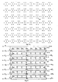
- La figure 2 est une vue de face partielle du support d'un tel dispositif ;
- La figure 3 est une vue schématique illustrant le fonctionnement du dispositif de la figure 2.
- Figure 2 is a partial front view of the support of such a device;
- FIG. 3 is a schematic view illustrating the operation of the device in FIG. 2.
Comme on peut le voir sur le dessin de la figure 2, le dispositif électronique de l'invention se présente sous la forme d'un support 10 découpé dans un matériau isolant et sur lequel sont installés les différents composants dudit dispositif. Ces composants sont constitués notamment par des diodes électroluminescentes D en saillie sur la face apparente du support et ordonnées selon le premier mode de présentation illustré à la figure la, en une matrice M7 ,n,As can be seen in the drawing in FIG. 2, the electronic device of the invention is in the form of a
En fait, pour des commodités pratiques de réalisation d'un tel dispositif, le support 10 est constitué par la juxtaposition de n/8 cartes 20 de diodes D ordonnées en matrice M'7,8 et est inséré dans un boîtier rectangulaire non représenté dont l'une des faces est transparente pour laisser apparaître l'affichage lumineux par des diodes D. Ce boîtier est relié à un organe de commande (clavier mémoire, etc ...) destiné à programmer les paramètres du message de l'information.In fact, for practical convenience of making such a device, the
Le fonctionnement d'une de ces cartes 20, illustré par le dessin de la figure 3 est le suivant.The operation of one of these
Chaque diode D des lignes de la matrice M'7,8 est connectée entre une alimentation en tension V et une des huit sorties (S1, S2, S3, ... S8) des registres à décalage R1, R2, ... R7 correspondant respectivement aux lignes 1, 2, ... 7.Each diode D of the lines of the matrix M ' 7,8 is connected between a voltage supply V and one of the eight outputs (S 1 , S 2 , S 3 , ... S 8 ) of the shift registers R 1 , R 2 , ... R 7 corresponding respectively to
Il en résulte que lorsque l'une des sorties S1, ... S8 est à l'état bas, la diode D branchée sur cette sortie émet de la lumière et valide l'élément de matrice correspondant. Au moyen du susdit organe de commande, il suffit alors d'envoyer sur les sept entrées E1, ... E7 des registres à décalage d'une carte 20, les paramètres du message de l'information sous la forme d'un langage binaire pour que celui-ci, reproduit par les diodes D sous la forme de caractères matriciels M" 7,5 se décale colonne par colonne de droite gauche et selon une vitesse de défilement proportionnelle à la base de temps desdits registres.It follows that when one of the outputs S 1 , ... S 8 is in the low state, the diode D connected to this output emits light and validates the corresponding matrix element. By means of the above-mentioned control member, it is then sufficient to send to the seven inputs E 1 , ... E 7 of the shift registers of a
Afin que le même message puisse défiler sur les autres cartes 20 du support 10, les sorties S8 des sept registres à décalage de la carte 20 sont reliées aux sept entrées E1,... E7 des registres à décalage de la carte suivante.So that the same message can scroll on the
Il est utile de préciser également que pour obtenir un défilement régulier du message, toutes les bases de temps de l'ensemble des registres à décalage installés sur un même support 10, sont déclenchées par une seule horloge réglable H, et de préférence sur le front montant de cette dernière.It is useful to also specify that to obtain a regular scrolling of the message, all the time bases of all the shift registers installed on the
Le message de l'information peut se présenter sur les cartes 20 du support 10 de deux manières différentes.The information message can be presented on the
La première consiste à faire apparaître le message progressivement sur le support de droite à gauche en mettant à l'état haut l'alimentation en tension V des diodes D pendant toute la durée de défilement de l'information.The first consists in making the message appear progressively on the support from right to left by setting high the voltage supply V of the diodes D throughout the duration of scrolling of the information.
La deuxième consiste à envoyer l'information variable des diodes D de la première colonne de la première carte 20 à la dernière colonne de la nème carte, pendant une période où l'alimentation en tension V des diodes est à l'état bas et où l'horloge réglable H est en service, puis la susdite information apparaît sur l'enseigne pendant une période réglable où l'alimentation en tension V des diodes est à l'état haut et l'horloge réglable H n'est pas en service.The second consists in sending the variable information from the diodes D of the first column of the
Cette deuxième possibilité permet ainsi de composer plusieurs lignes d'un message se présentant sous la forme d'un texte et qui apparaîtront simultanément et instantanément sur le support 10.This second possibility thus makes it possible to compose several lines of a message in the form of a text and which will appear simultaneously and instantaneously on the
Bien entendu, l'invention n'est pas limitée au mode de réalisation ci-dessus décrit, mais s'étend à tout variante conforme à son esprit.Of course, the invention is not limited to the embodiment described above, but extends to any variant in accordance with its spirit.
Claims (14)
Applications Claiming Priority (2)
| Application Number | Priority Date | Filing Date | Title |
|---|---|---|---|
| FR8119792A FR2514921A1 (en) | 1981-10-16 | 1981-10-16 | SCREEN DISPLAY LUMINOUS SIGN OF VARIABLE INFORMATION: ELECTRONIC METHOD AND DEVICE IMPLEMENTED THEREIN |
| FR8119792 | 1981-10-16 |
Publications (2)
| Publication Number | Publication Date |
|---|---|
| EP0077694A2 true EP0077694A2 (en) | 1983-04-27 |
| EP0077694A3 EP0077694A3 (en) | 1984-09-19 |
Family
ID=9263256
Family Applications (1)
| Application Number | Title | Priority Date | Filing Date |
|---|---|---|---|
| EP82400728A Withdrawn EP0077694A3 (en) | 1981-10-16 | 1982-04-23 | Illuminated moving display for variable information, method and electronic apparatus therefor |
Country Status (2)
| Country | Link |
|---|---|
| EP (1) | EP0077694A3 (en) |
| FR (1) | FR2514921A1 (en) |
Citations (3)
| Publication number | Priority date | Publication date | Assignee | Title |
|---|---|---|---|---|
| GB1273667A (en) * | 1970-08-05 | 1972-05-10 | Standard Telephones Cables Ltd | Improvements in or relating to display devices |
| US4024531A (en) * | 1974-03-05 | 1977-05-17 | National Research Development Corporation | Display devices |
| US4162493A (en) * | 1976-01-13 | 1979-07-24 | Random Electronics International Pty. Limited | Graphic display systems |
-
1981
- 1981-10-16 FR FR8119792A patent/FR2514921A1/en not_active Withdrawn
-
1982
- 1982-04-23 EP EP82400728A patent/EP0077694A3/en not_active Withdrawn
Patent Citations (3)
| Publication number | Priority date | Publication date | Assignee | Title |
|---|---|---|---|---|
| GB1273667A (en) * | 1970-08-05 | 1972-05-10 | Standard Telephones Cables Ltd | Improvements in or relating to display devices |
| US4024531A (en) * | 1974-03-05 | 1977-05-17 | National Research Development Corporation | Display devices |
| US4162493A (en) * | 1976-01-13 | 1979-07-24 | Random Electronics International Pty. Limited | Graphic display systems |
Also Published As
| Publication number | Publication date |
|---|---|
| EP0077694A3 (en) | 1984-09-19 |
| FR2514921A1 (en) | 1983-04-22 |
Similar Documents
| Publication | Publication Date | Title |
|---|---|---|
| FR2582838A1 (en) | ELECTRONIC CALENDAR ATTAINING ATTENTION AND SHEET USED IN THIS CALENDAR | |
| CH618283A5 (en) | ||
| NO157596B (en) | DEVICE FOR PRESENTATION OF INFORMATION. | |
| FR2524183A1 (en) | DISPLAY APPARATUS COMPRISING A MATRIX COMPOSED OF A NETWORK OF ELEMENTS THAT CAN BE ELECTRICALLY ACTIVE | |
| US4289383A (en) | Lighted dot matrix display | |
| US20070247832A1 (en) | Fan with Bladers and Method for Displaying Illuminated Pictoral Elements | |
| EP0077694A2 (en) | Illuminated moving display for variable information, method and electronic apparatus therefor | |
| US3837102A (en) | Indicia display device | |
| EP0644469A1 (en) | Analogical timepiece with at least an universal time display | |
| FR2576430A1 (en) | Linear analogue watch | |
| FR2543340A3 (en) | Electronic control device comprising a display device using liquid crystals | |
| US3629655A (en) | Luminous display device | |
| EP0054451B1 (en) | Display device employing segments and points, particularly applicable to arabian writing | |
| US6329926B1 (en) | Visual display devices | |
| FR2694116A1 (en) | Route indicator panel for use at bus stop - has illuminated section representing bus on route, allowing estimation of waiting time until arrival of next bus | |
| EP0327787A1 (en) | Binary clock | |
| FR2570537A1 (en) | Method of control of the display of graphics on an assembly of electroluminescent diodes and control means for implementing the method | |
| FR2634432A1 (en) | Device for the control of the direction change indicators of a motor vehicle | |
| FR2466819A1 (en) | Optical fibre enhanced display - uses fibres illuminated from nearby source to form design on fixed reflecting sign | |
| JP2519945B2 (en) | Data imprinting device for camera and camera | |
| EP0054492A1 (en) | Device for displaying information in an image | |
| RU2076469C1 (en) | Multidigit semiconductor indicator | |
| FR2658349A1 (en) | Electronic name display apparatus | |
| FR2743440A1 (en) | Portable writer and eraser to mark prices on thermosensitive paper | |
| FR2646534A1 (en) | Process for the electro-optical display of the time in analog form and electronic device enabling its implementation |
Legal Events
| Date | Code | Title | Description |
|---|---|---|---|
| PUAI | Public reference made under article 153(3) epc to a published international application that has entered the european phase |
Free format text: ORIGINAL CODE: 0009012 |
|
| AK | Designated contracting states |
Designated state(s): AT BE CH DE FR GB IT LI LU NL SE |
|
| PUAL | Search report despatched |
Free format text: ORIGINAL CODE: 0009013 |
|
| AK | Designated contracting states |
Designated state(s): AT BE CH DE FR GB IT LI LU NL SE |
|
| STAA | Information on the status of an ep patent application or granted ep patent |
Free format text: STATUS: THE APPLICATION IS DEEMED TO BE WITHDRAWN |
|
| 18D | Application deemed to be withdrawn |
Effective date: 19841031 |
|
| RIN1 | Information on inventor provided before grant (corrected) |
Inventor name: DAHAN, RENE CLAUDE |