EP0076648A2 - Electrodeless fluorescent light source - Google Patents
Electrodeless fluorescent light source Download PDFInfo
- Publication number
- EP0076648A2 EP0076648A2 EP82305190A EP82305190A EP0076648A2 EP 0076648 A2 EP0076648 A2 EP 0076648A2 EP 82305190 A EP82305190 A EP 82305190A EP 82305190 A EP82305190 A EP 82305190A EP 0076648 A2 EP0076648 A2 EP 0076648A2
- Authority
- EP
- European Patent Office
- Prior art keywords
- envelope
- ultraviolet radiation
- electrodeless lamp
- fill material
- visible light
- Prior art date
- Legal status (The legal status is an assumption and is not a legal conclusion. Google has not performed a legal analysis and makes no representation as to the accuracy of the status listed.)
- Granted
Links
Images
Classifications
-
- H—ELECTRICITY
- H01—ELECTRIC ELEMENTS
- H01J—ELECTRIC DISCHARGE TUBES OR DISCHARGE LAMPS
- H01J65/00—Lamps without any electrode inside the vessel; Lamps with at least one main electrode outside the vessel
- H01J65/04—Lamps in which a gas filling is excited to luminesce by an external electromagnetic field or by external corpuscular radiation, e.g. for indicating plasma display panels
- H01J65/042—Lamps in which a gas filling is excited to luminesce by an external electromagnetic field or by external corpuscular radiation, e.g. for indicating plasma display panels by an external electromagnetic field
- H01J65/046—Lamps in which a gas filling is excited to luminesce by an external electromagnetic field or by external corpuscular radiation, e.g. for indicating plasma display panels by an external electromagnetic field the field being produced by using capacitive means around the vessel
Definitions
- This invention relates to electromagnetic discharge apparatus. More particularly, it is concerned with electrodeless fluorescent light sources.
- Electrodeless light sources which operate by coupling high frequency power to an arc discharge in an electrodeless lamp have been developed. These light sources typically include a high frequency power source connected to a coupling fixture having an inner conductor and an outer conductor disposed around the inner conductor. The electrodeless lamp is positioned adjacent to the. end of the inner conductor. High frequency power is coupled to a light emitting electromagnetic discharge within the electrodeless lamp. A portion of the coupling fixture passes radiation at the frequencies of light produced, this permitting the use of the apparatus as a light source.
- Electrodeless fluorescent light sources are known in which the electrodeless lamp emits ultraviolet radiation which impinges on phosphors which in turn emit visible light when the ultraviolet radiation is absorbed.
- Examples of fluorescent light sources of this general type are disclosed in Patent No. 4,119,889 to Donald D. Hollister, Patent No. 4,005,330 to Homer H. Glascock, Jr. and John M. Anderson, 4,189,661 to Paul 0. Haugsjaa and Edward F. White, and 4,266,167 to Joseph M. Proud and Donald H. Baird.
- the apparatus comprises an electrodeless lamp having an inner envelope of a substance transparent to ultraviolet radiation.
- the inner envelope encloses a fill material comprising a material selected from the group consisting of a metal iodide and iodine.
- Means are provided for coupling high frequency power to the fill material within the inner envelope to vaporize and excite the fill material thus producing ultraviolet radiation.
- An outer envelope of a substance transparent to visible light surrounds the inner envelope and is spaced from it. Fluorescing material which emits visible light upon absorption of ultraviolet radiation is disposed between the outer surface of the inner envelope and the inner surface of the outer envelope.
- the apparatus may comprise an electrodeless lamp having an envelope enclosing a fill material comprising a material selected from the group consisting of a metal iodide and iodine with a coating of solid phosphor material which emits visible light adherent to the surface of the envelope.
- the metal iodide or iodine provides a source of iodine atoms which are excited to a high energy state when high frequency power is applied.
- the excited iodine atoms emit ultraviolet radiation upon photon emission transition to a lower energy state. Further explanation of the manner in which the metal iodide or iodine produces ultraviolet radiation upon high frequency excitation is provided in the above-mentioned application of Proud and Johnson.
- the fluorescing material may be a gaseous phosphor material located in the space between the inner and outer envelopes, a solid phosphor material adherent either to the outer surface of the inner envelope or to the inner surface of the outer envelope, or a combination of gaseous and solid phosphor materials. The fluorescing material is excited by the ultraviolet radiation and in turn emits radiation in the visible light range.
- the apparatus 10 includes an electrodeless lamp 11 containing a fill material 12.
- the electrodeless lamp 11 is supported within a fixture 13 which couples power from a high frequency power source 14 to the fill material of the electrodeless lamp.
- the electrodeless lamp forms a termination load for the fixture.
- the electrodeless lamp 11 has a sealed envelope made of a suitable material which is transparent to ultraviolet radiation, for example, fused silica or aluminum oxide.
- the fill material 12 within the lamp envelope 11 includes a metal iodide or iodine.
- the metal iodide preferably may be either cadmium iodide or mercuric iodide.
- a fill material of a metal iodide also contains a buffer gas, such as argon, xenon, neon, or nitrogen at a pressure of from 1 to 50 torr.
- the coupling fixture 13 includes an inner conductor 15, and an outer conductor 16 disposed around the inner conductor.
- An outer envelope 17 of a material transparent to visible light surrounds and is spaced from the electrodeless lamp 11.
- the outer envelope 17 is appropriately sealed.
- the outer conductor 16 may be of conductive mesh so as to permit visible light to pass therethrough, and may be contained within the outer envelope 17.
- the outer conductor 16 provides shielding at the operating frequencies while permitting the passage of light.
- the electrodeless lamp 11 is supported between a first metal electrode 18 at one end of the inner conductor 15 and a second metal electrode 19 connected to the outer conductor 16.
- the other ends of the inner and outer conductors are arranged in a coaxial configuration for coupling to the power source 14.
- the power source 14 preferably is a source of continuous wave RF excitation in those radio frequencies allocated for industrial, scientific, or medical usage located at 13.56, 27.12, 40.68, 915, or 2450 MHz. Most desirably, the RF frequency is in the range of from 902 to 928 MHz. However, useful frequencies lie within the range of from 1 MHz to 10GHz. Structural details of electromagnetic discharge apparatus related to those illustrated schematically herein are disclosed in application (D-22807) filed concurrently herewith by Joseph M. Proud, Robert K. Smith, and Charles N. Fallier entitled
- the space 20 between the inner envelope of the electrodeless lamp 11 and the outer envelope 17 contains a fluorescing material in the form of a gaseous phosphor.
- the gaseous phosphor composition must be such that it is chemically compatible with the materials forming the sealed space 20.
- the gaseous phosphor may be chosen from the mercury halides, preferably mercuric chloride and mercuric bromide.
- the mercury halides in the gaseous state absorb ultraviolet radiation and subsequently disassociate into a halide atom and an excited mercury-halide molecule.
- the excited mercury-halide molecule then fluoresces emitting visible light.
- the material thus exhibits the characteristics of a phosphor; a material which absorbs radiation at one wave length and fluoresces at some longer wave length.
- the electrodeless lamp 11 thus provides a strong source of ultraviolet radiation which impinges on the gaseous phosphor in the space 20 causing it, in turn, to emit visible light.
- the space 20 reach some equilibrium temperature during operation of the lamp for purposes of creating an appropriate vapor pressure of the gaseous phosphor material.
- the vapor pressure of the gaseous phosphor material should be sufficient to vaporize enough material so as to absorb the exciting ultraviolet radiation before it impinges on the outer envelope.
- Heating to temperatures in the range of 20°C to 100°C may be accomplished by dissipated radio frequency power from the space within the electrodeless lamp 11, and the subsequent transfer of heat from the inner envelope by conduction and infrared radiation to the space 20 and the outer envelope 17.
- the temperature attained at equilibrium depends upon a number of factors including the applied RF power level, the sizes of various elements of the apparatus, and the material composition of those elements.
- Fig. 2 illustrates an electromagnetic discharge apparatus 30 generally similar in physical structure to that of Fig. 1.
- the apparatus 30 includes an electrodeless lamp 31 having a fill material 32 of a metal iodide and a buffer gas or of iodine in accordance with the teachings of the Proud and Johnson application.
- An RF coupling fixture 33 has an inner conductor 35 and an outer mesh conductor 36 which is contained within an outer envelope 37 of a material which is transparent to visible light.
- the electrodess lamp 31 is supported by electrodes 38 and 39 from the inner and outer conductors, respectively, for applying RF power from a source 34 to the fill material within the electrodeless lamp 31.
- the fluorescing material is a layer of a solid phosphor material 41 which is adherent to the inner surface of the outer envelope 37.
- the solid phosphor may be any of the well-known phosphors widely employed in the fluorescent lighting industry.
- the space 40 between the inner and outer envelopes contains a vacuum or an inert gas; that is a material which does not absorb the ultraviolet radiation from the electrodeless lamp 31.
- the space 40 between the inner and outer envelopes may contain a gaseous phosphor material.
- the ultraviolet light radiated from the electrodeless lamp 31 the dimensions of the space 40, and the amount and characteristics of the gaseous and solid phosphor materials must be such that all the ultraviolet is not absorbed before it reaches and impinges upon the solid phosphor 41.
- the optical properties of the gaseous medium used and its density affect the results. The optical properties are largely determined by the vapor pressure in the space 40 and the operating temperature, as well as the cold spot temperature along the boundaries of the space 40.
- Fig. 3 illustrates an electromagnetic discharge apparatus 50 having the same general structural configuration as those illustrated in Figs. 1 and 2.
- the apparatus includes an electrodeless lamp 51 having a fill material 52 of a metal iodide or iodine whereby the lamp is a source of ultraviolet radiation.
- the electrodeless lamp 51 is mounted within an RF coupling fixture 53 having an inner conductor 55 and an outer conductor 56 supported within an outer envelope 57 which is transparent to visible light.
- the electrodeless lamp 51 is supported by electrodes 58 and 59 connected to the inner and outer conductors, respectively.
- the conductors 35, 36 are connected to a high frequency power source 54.
- the fluorescing material is provided by a solid phosphor material 62 which is adherent to the outer surface of the inner envelope of the electrodeless lamp 51.
- the space 60 between the inner and outer envelopes advantageously contain a vacuum or an inert gas.
- the phosphor material 62 may be a standard lighting phosphor similar to that employed in the apparatus of Fig. 2.
- Fig. 4 is a schematic representation of an alternative embodiment of an electromagnetic discharge apparatus 70 in accordance with the present invention.
- the apparatus 70 includes an electrodeless lamp 71 having a sealed envelope in the shape of a reentrant cylinder providing a generally annular discharge region 72.
- the fill material of the lamp within the space 72 includes a metal iodide or iodine as described hereinabove.
- the RF coupling arrangement includes a center electrode 78 disposed within the internal reentrant cavity in the envelope 71.
- An outer conductive mesh 76 encircles the envelope of the lamp 71 and the center electrode 78.
- the center electrode 78 and outer conductor 76 are coupled by a suitable coaxial arrangement to a high frequency power source 74.
- a radio frequency electric field is produced between the center electrode 78 and the mesh 76 causing ionization and breakdown of the fill material 72 which emits ultraviolet radiation.
- the fluorescing material is a solid phosphor material 82 adherent to the inner surface of the envelope of the lamp 71. Electromagnetic discharge apparatus related to that shown in Fig. 4 is described in U.S. Patent No. 4,266,167 to Proud and Baird.
- the apparatus 90 includes an electrodeless lamp 91 having an inner envelope enclosing a fill material 92 of a metal iodide and a buffer gas or of iodine.
- the envelope of the lamp 91 is encircled by an intermediate sealed envelope 93 of a substance which is transparent to ultraviolet and visible light.
- the intermediate envelope 93 is contiguous with the inner envelope and defines therewith an annular region 94 encircling the lamp 91.
- the annular region 94 contains a gaseous phosphor material as described hereinabove.
- An RF coupling fixture 95 includes an inner conductor 96 and an outer conductor 97 which is supported in an outer envelope 98 of a material transparent to visible light.
- the electrodeless lamp 91 together with the intermediate envelope 93 are supported on electrodes 99 and 100 from the inner and outer conductors, respectively.
- R F power is applied to the conductors 96 and 97 through a coaxial arrangement to a high frequency power source 104.
- the space 105 between the intermediate envelope 92 and the outer envelope 98 contains a vacuum or an inert gas.
- a coating of solid phosphor material 102 is adherent to the outer surface of the intermediate envelope 93.
- the fill material therein emits ultraviolet radiation.
- the ultraviolet radiation photoexcites the gaseous phosphor material in the space 94 and it emits visible light. Not all of the ultraviolet radiation is absorbed by the gases in the space 94.
- Some of the ultraviolet radiation passes through the intermediate envelope 93 to impinge on the solid phosphor material 102, which in turn also emits visible light.
- Fig. 6 illustrates a modification of the embodiment of Fig. 5.
- the apparatus 110 includes an electrodeless lamp 111 having an inner envelope enclosing a fill material 112 of a metal iodide and an inert buffer gas or of iodine.
- An intermediate envelope 112 encircles the lamp 111 to form an annular region 114 which contains a gaseous phosphor material.
- An RF coupling fixture 115 includes an inner conductor 116 and a conductive mesh outer conductor 117 contained in an outer envelope 118.
- the combination of the electrodeless lamp 111 and intermediate envelope 112 are supported by electrodes 119 and 120 from the inner and outer conductors, respectively.
- RF power is applied to the conductors 116 and 117 through coaxial connections to a high frequency power source 124.
- the space 125 between the intermediate envelope 112 and the outer envelope 118 contains a vacuum or an inert gas.
- a coating of solid phosphor material 122 is adherent to the inner surface of the outer envelope 118.
- the fill material therein emits ultraviolet radiation.
- the ultraviolet radiation photoexcites the gaseous phosphor material in the space 114 and it emits visible light. Not all of the ultraviolet radiation is absorbed by the gases in the spaces 114.
- Some of the ultraviolet radiation passes through the intermediate envelope 113 and the space 125 to impinge on the solid phosphor material 122, which in turn also emits visible light.
- electromagnetic discharge apparatus which serves as an electrodeless fluorescent light source.
- the apparatus employs an electrodeless lamp as described in the aforementioned application of Proud and Johnson as a source of ultraviolet radiation and fluorescing material arranged to convert the ultraviolet radiation to visible light.
Abstract
Description
- This invention is related to subject matter disclosed in application Serial No. (D-22687) filed concurrently herewith by Joseph M. Proud and Stephen G. Johnson entitled "Electrodeless Ultraviolet Light Source."
- This invention relates to electromagnetic discharge apparatus. More particularly, it is concerned with electrodeless fluorescent light sources.
- Electrodeless light sources which operate by coupling high frequency power to an arc discharge in an electrodeless lamp have been developed. These light sources typically include a high frequency power source connected to a coupling fixture having an inner conductor and an outer conductor disposed around the inner conductor. The electrodeless lamp is positioned adjacent to the. end of the inner conductor. High frequency power is coupled to a light emitting electromagnetic discharge within the electrodeless lamp. A portion of the coupling fixture passes radiation at the frequencies of light produced, this permitting the use of the apparatus as a light source.
- Electrodeless fluorescent light sources are known in which the electrodeless lamp emits ultraviolet radiation which impinges on phosphors which in turn emit visible light when the ultraviolet radiation is absorbed. Examples of fluorescent light sources of this general type are disclosed in Patent No. 4,119,889 to Donald D. Hollister, Patent No. 4,005,330 to Homer H. Glascock, Jr. and John M. Anderson, 4,189,661 to Paul 0. Haugsjaa and Edward F. White, and 4,266,167 to Joseph M. Proud and Donald H. Baird.
- It is an object of the present invention to provide an improved electromagnetic discharge apparatus.
- It is another object of the present invention to provide an electrodeless fluorescent light source.
- An improved fluorescent light source is provided by electromagnetic discharge apparatus in accordance with the present invention. The apparatus comprises an electrodeless lamp having an inner envelope of a substance transparent to ultraviolet radiation. The inner envelope encloses a fill material comprising a material selected from the group consisting of a metal iodide and iodine. Means are provided for coupling high frequency power to the fill material within the inner envelope to vaporize and excite the fill material thus producing ultraviolet radiation. An outer envelope of a substance transparent to visible light surrounds the inner envelope and is spaced from it. Fluorescing material which emits visible light upon absorption of ultraviolet radiation is disposed between the outer surface of the inner envelope and the inner surface of the outer envelope. Alternatively the apparatus may comprise an electrodeless lamp having an envelope enclosing a fill material comprising a material selected from the group consisting of a metal iodide and iodine with a coating of solid phosphor material which emits visible light adherent to the surface of the envelope.
- The metal iodide or iodine provides a source of iodine atoms which are excited to a high energy state when high frequency power is applied. The excited iodine atoms emit ultraviolet radiation upon photon emission transition to a lower energy state. Further explanation of the manner in which the metal iodide or iodine produces ultraviolet radiation upon high frequency excitation is provided in the above-mentioned application of Proud and Johnson. The fluorescing material may be a gaseous phosphor material located in the space between the inner and outer envelopes, a solid phosphor material adherent either to the outer surface of the inner envelope or to the inner surface of the outer envelope, or a combination of gaseous and solid phosphor materials. The fluorescing material is excited by the ultraviolet radiation and in turn emits radiation in the visible light range.
- In the drawings:
- Fig. 1 is a schematic representation of an electrodeless radio frequency coupled discharge fluorescent light source in accordance with the present invention;
- Fig. 2 is a schematic representation of a modification of the fluorescent light source of Fig. 1;
- Fig. 3 is a schematic representation of another modification of the electrodeless light source of Figs. 1 and 2;
- Fig. 4 is a schematic representation of an alternative form of an electrodeless fluorescent light source in accordance with the present invention;
- Fig. 5 is a schematic representation of another alternative form of an electrodeless fluorescent light source in accordance with the present invention; and
- Fig. 6 is a schematic representation of a modification of the alternative form of Fig. 5.
- For a better understanding of the present invention, together with other and further objects, advantages, and capabilities thereof, reference is made to the following discussion and appended claims in connection with the above-described drawings.
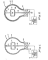
- One embodiment of an electromagnetic discharge apparatus in accordance with the present invention is illustrated in Fig. 1. The
apparatus 10 includes anelectrodeless lamp 11 containing afill material 12. Theelectrodeless lamp 11 is supported within afixture 13 which couples power from a highfrequency power source 14 to the fill material of the electrodeless lamp. The electrodeless lamp forms a termination load for the fixture. - The
electrodeless lamp 11 has a sealed envelope made of a suitable material which is transparent to ultraviolet radiation, for example, fused silica or aluminum oxide. Thefill material 12 within thelamp envelope 11 includes a metal iodide or iodine. The metal iodide preferably may be either cadmium iodide or mercuric iodide. A fill material of a metal iodide also contains a buffer gas, such as argon, xenon, neon, or nitrogen at a pressure of from 1 to 50 torr. - The
coupling fixture 13 includes aninner conductor 15, and anouter conductor 16 disposed around the inner conductor. Anouter envelope 17 of a material transparent to visible light surrounds and is spaced from theelectrodeless lamp 11. Theouter envelope 17 is appropriately sealed. Theouter conductor 16 may be of conductive mesh so as to permit visible light to pass therethrough, and may be contained within theouter envelope 17. Theouter conductor 16 provides shielding at the operating frequencies while permitting the passage of light. Theelectrodeless lamp 11 is supported between afirst metal electrode 18 at one end of theinner conductor 15 and asecond metal electrode 19 connected to theouter conductor 16. The other ends of the inner and outer conductors are arranged in a coaxial configuration for coupling to thepower source 14. - In order to achieve electrodeless discharge it is necessary to employ RF power capable of penetrating the lamp envelope while being absorbed strongly in the low pressure discharge plasma contained therein. The
power source 14 preferably is a source of continuous wave RF excitation in those radio frequencies allocated for industrial, scientific, or medical usage located at 13.56, 27.12, 40.68, 915, or 2450 MHz. Most desirably, the RF frequency is in the range of from 902 to 928 MHz. However, useful frequencies lie within the range of from 1 MHz to 10GHz. Structural details of electromagnetic discharge apparatus related to those illustrated schematically herein are disclosed in application (D-22807) filed concurrently herewith by Joseph M. Proud, Robert K. Smith, and Charles N. Fallier entitled - The
space 20 between the inner envelope of theelectrodeless lamp 11 and theouter envelope 17 contains a fluorescing material in the form of a gaseous phosphor. The gaseous phosphor composition must be such that it is chemically compatible with the materials forming the sealedspace 20. The gaseous phosphor may be chosen from the mercury halides, preferably mercuric chloride and mercuric bromide. The mercury halides in the gaseous state absorb ultraviolet radiation and subsequently disassociate into a halide atom and an excited mercury-halide molecule. The excited mercury-halide molecule then fluoresces emitting visible light. The material thus exhibits the characteristics of a phosphor; a material which absorbs radiation at one wave length and fluoresces at some longer wave length. - As explained in the aforementioned application of Proud and Johnson when high frequency power is applied to the
electrodeless lamp 11, a discharge is initiated in the gas which warms the contents of the lamp causing an increase in the iodide or iodine vapor pressure. Iodide or iodine molecules are dissociated in the discharge to yield iodine atoms. The iodine atoms are electronically excited to a high energy state and emit ultraviolet radiation at 206.2 nm upon photon emission transition to a lower state. Of course, additional emissions will be produced in the visible and ultraviolet portions of the spectrum from radiative transitions in I, I2, Hg, HgI2, HgI, Cd, CdI2, CdI, etc. depending on the composition of the fill material. More than 10% of the applied RF power can be converted to ultraviolet radiation. Theelectrodeless lamp 11 thus provides a strong source of ultraviolet radiation which impinges on the gaseous phosphor in thespace 20 causing it, in turn, to emit visible light. - Generally, it is required that the
space 20 reach some equilibrium temperature during operation of the lamp for purposes of creating an appropriate vapor pressure of the gaseous phosphor material. The vapor pressure of the gaseous phosphor material should be sufficient to vaporize enough material so as to absorb the exciting ultraviolet radiation before it impinges on the outer envelope. Heating to temperatures in the range of 20°C to 100°C may be accomplished by dissipated radio frequency power from the space within theelectrodeless lamp 11, and the subsequent transfer of heat from the inner envelope by conduction and infrared radiation to thespace 20 and theouter envelope 17. The temperature attained at equilibrium depends upon a number of factors including the applied RF power level, the sizes of various elements of the apparatus, and the material composition of those elements. - Fig. 2 illustrates an
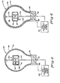
electromagnetic discharge apparatus 30 generally similar in physical structure to that of Fig. 1. Theapparatus 30 includes anelectrodeless lamp 31 having afill material 32 of a metal iodide and a buffer gas or of iodine in accordance with the teachings of the Proud and Johnson application. AnRF coupling fixture 33 has aninner conductor 35 and anouter mesh conductor 36 which is contained within anouter envelope 37 of a material which is transparent to visible light. Theelectrodess lamp 31 is supported byelectrodes source 34 to the fill material within theelectrodeless lamp 31. The fluorescing material is a layer of asolid phosphor material 41 which is adherent to the inner surface of theouter envelope 37. The solid phosphor may be any of the well-known phosphors widely employed in the fluorescent lighting industry. Thespace 40 between the inner and outer envelopes contains a vacuum or an inert gas; that is a material which does not absorb the ultraviolet radiation from theelectrodeless lamp 31. - In an alternative arrangement of the
apparatus 30 illustrated in Fig. 2 thespace 40 between the inner and outer envelopes may contain a gaseous phosphor material. In order to provide effective efficient light producing operation the ultraviolet light radiated from theelectrodeless lamp 31, the dimensions of thespace 40, and the amount and characteristics of the gaseous and solid phosphor materials must be such that all the ultraviolet is not absorbed before it reaches and impinges upon thesolid phosphor 41. In particular, the optical properties of the gaseous medium used and its density affect the results. The optical properties are largely determined by the vapor pressure in thespace 40 and the operating temperature, as well as the cold spot temperature along the boundaries of thespace 40. - Fig. 3 illustrates an
electromagnetic discharge apparatus 50 having the same general structural configuration as those illustrated in Figs. 1 and 2. The apparatus includes anelectrodeless lamp 51 having afill material 52 of a metal iodide or iodine whereby the lamp is a source of ultraviolet radiation. Theelectrodeless lamp 51 is mounted within anRF coupling fixture 53 having aninner conductor 55 and anouter conductor 56 supported within anouter envelope 57 which is transparent to visible light. Theelectrodeless lamp 51 is supported byelectrodes conductors frequency power source 54. - In this apparatus the fluorescing material is provided by a
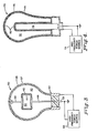
solid phosphor material 62 which is adherent to the outer surface of the inner envelope of theelectrodeless lamp 51. Thespace 60 between the inner and outer envelopes advantageously contain a vacuum or an inert gas. Thephosphor material 62 may be a standard lighting phosphor similar to that employed in the apparatus of Fig. 2. - Fig. 4 is a schematic representation of an alternative embodiment of an
electromagnetic discharge apparatus 70 in accordance with the present invention. Theapparatus 70 includes anelectrodeless lamp 71 having a sealed envelope in the shape of a reentrant cylinder providing a generallyannular discharge region 72. The fill material of the lamp within thespace 72 includes a metal iodide or iodine as described hereinabove. The RF coupling arrangement includes acenter electrode 78 disposed within the internal reentrant cavity in theenvelope 71. An outerconductive mesh 76 encircles the envelope of thelamp 71 and thecenter electrode 78. Thecenter electrode 78 andouter conductor 76 are coupled by a suitable coaxial arrangement to a highfrequency power source 74. A radio frequency electric field is produced between thecenter electrode 78 and themesh 76 causing ionization and breakdown of thefill material 72 which emits ultraviolet radiation. As indicated in Fig. 4 the fluorescing material is asolid phosphor material 82 adherent to the inner surface of the envelope of thelamp 71. Electromagnetic discharge apparatus related to that shown in Fig. 4 is described in U.S. Patent No. 4,266,167 to Proud and Baird. - Another embodiment of the present invention is illustrated in Fig. 5. The
apparatus 90 includes anelectrodeless lamp 91 having an inner envelope enclosing afill material 92 of a metal iodide and a buffer gas or of iodine. The envelope of thelamp 91 is encircled by an intermediate sealedenvelope 93 of a substance which is transparent to ultraviolet and visible light. Theintermediate envelope 93 is contiguous with the inner envelope and defines therewith an annular region 94 encircling thelamp 91. The annular region 94 contains a gaseous phosphor material as described hereinabove. AnRF coupling fixture 95 includes aninner conductor 96 and anouter conductor 97 which is supported in anouter envelope 98 of a material transparent to visible light. Theelectrodeless lamp 91 together with theintermediate envelope 93 are supported onelectrodes conductors frequency power source 104. Thespace 105 between theintermediate envelope 92 and theouter envelope 98 contains a vacuum or an inert gas. A coating ofsolid phosphor material 102 is adherent to the outer surface of theintermediate envelope 93. When high frequency power is applied to theelectrodeless lamp 91, the fill material therein emits ultraviolet radiation. The ultraviolet radiation photoexcites the gaseous phosphor material in the space 94 and it emits visible light. Not all of the ultraviolet radiation is absorbed by the gases in the space 94. Some of the ultraviolet radiation passes through theintermediate envelope 93 to impinge on thesolid phosphor material 102, which in turn also emits visible light. - Fig. 6 illustrates a modification of the embodiment of Fig. 5. The
apparatus 110 includes anelectrodeless lamp 111 having an inner envelope enclosing afill material 112 of a metal iodide and an inert buffer gas or of iodine. Anintermediate envelope 112 encircles thelamp 111 to form anannular region 114 which contains a gaseous phosphor material. AnRF coupling fixture 115 includes aninner conductor 116 and a conductive meshouter conductor 117 contained in anouter envelope 118. The combination of theelectrodeless lamp 111 andintermediate envelope 112 are supported byelectrodes conductors frequency power source 124. Thespace 125 between theintermediate envelope 112 and theouter envelope 118 contains a vacuum or an inert gas. A coating ofsolid phosphor material 122 is adherent to the inner surface of theouter envelope 118. When high frequency power is applied to theelectrodeless lamp 111, the fill material therein emits ultraviolet radiation. The ultraviolet radiation photoexcites the gaseous phosphor material in thespace 114 and it emits visible light. Not all of the ultraviolet radiation is absorbed by the gases in thespaces 114. Some of the ultraviolet radiation passes through theintermediate envelope 113 and thespace 125 to impinge on thesolid phosphor material 122, which in turn also emits visible light. - Thus, there is provided electromagnetic discharge apparatus which serves as an electrodeless fluorescent light source. The apparatus employs an electrodeless lamp as described in the aforementioned application of Proud and Johnson as a source of ultraviolet radiation and fluorescing material arranged to convert the ultraviolet radiation to visible light.
- While there has been shown and described what are considered preferred embodiments of the present invention, it will be obvious to those skilled in the art that various changes and modifications may be made therein without departing- from the invention as defined by the appended claims.
Claims (11)
Applications Claiming Priority (2)
| Application Number | Priority Date | Filing Date | Title |
|---|---|---|---|
| US06/307,556 US4427923A (en) | 1981-10-01 | 1981-10-01 | Electrodeless fluorescent light source |
| US307556 | 1981-10-01 |
Publications (3)
| Publication Number | Publication Date |
|---|---|
| EP0076648A2 true EP0076648A2 (en) | 1983-04-13 |
| EP0076648A3 EP0076648A3 (en) | 1983-10-26 |
| EP0076648B1 EP0076648B1 (en) | 1988-01-07 |
Family
ID=23190265
Family Applications (1)
| Application Number | Title | Priority Date | Filing Date |
|---|---|---|---|
| EP82305190A Expired EP0076648B1 (en) | 1981-10-01 | 1982-09-30 | Electrodeless fluorescent light source |
Country Status (4)
| Country | Link |
|---|---|
| US (1) | US4427923A (en) |
| EP (1) | EP0076648B1 (en) |
| CA (1) | CA1189123A (en) |
| DE (1) | DE3277952D1 (en) |
Cited By (2)
| Publication number | Priority date | Publication date | Assignee | Title |
|---|---|---|---|---|
| EP0515711A1 (en) * | 1991-05-27 | 1992-12-02 | Heraeus Noblelight GmbH | High power radiator |
| CN1294702C (en) * | 2001-07-16 | 2007-01-10 | 格尔德·赖梅 | Optoelectronic device for detecting position and movement and method associated therewith |
Families Citing this family (24)
| Publication number | Priority date | Publication date | Assignee | Title |
|---|---|---|---|---|
| US4792725A (en) * | 1985-12-10 | 1988-12-20 | The United States Of America As Represented By The Department Of Energy | Instantaneous and efficient surface wave excitation of a low pressure gas or gases |
| US4937503A (en) * | 1988-04-11 | 1990-06-26 | Gte Laboratories Incorporated | Fluorescent light source based on a phosphor excited by a molecular discharge |
| US5013976A (en) * | 1989-12-26 | 1991-05-07 | Gte Products Corporation | Electrodeless glow discharge lamp |
| US5493184A (en) * | 1990-10-25 | 1996-02-20 | Fusion Lighting, Inc. | Electrodeless lamp with improved efficiency |
| US5397966A (en) * | 1992-05-20 | 1995-03-14 | Diablo Research Corporation | Radio frequency interference reduction arrangements for electrodeless discharge lamps |
| US5300860A (en) * | 1992-10-16 | 1994-04-05 | Gte Products Corporation | Capacitively coupled RF fluorescent lamp with RF magnetic enhancement |
| US5325024A (en) * | 1992-10-16 | 1994-06-28 | Gte Products Corporation | Light source including parallel driven low pressure RF fluorescent lamps |
| US5289085A (en) * | 1992-10-16 | 1994-02-22 | Gte Products Corporation | Capacitively driven RF light source having notched electrode for improved starting |
| DE19526211A1 (en) * | 1995-07-18 | 1997-01-23 | Patent Treuhand Ges Fuer Elektrische Gluehlampen Mbh | Process for operating discharge lamps or emitters |
| US5990624A (en) * | 1995-09-25 | 1999-11-23 | Matsushita Electric Works R&D Laboratory, Inc. | Color sulfur lamp including means for intercepting and re-mitting light of a desired spectral distribution |
| JP3202910B2 (en) * | 1995-12-04 | 2001-08-27 | 松下電器産業株式会社 | Microwave discharge lamp |
| US5834784A (en) * | 1997-05-02 | 1998-11-10 | Triton Thalassic Technologies, Inc. | Lamp for generating high power ultraviolet radiation |
| JP2002503387A (en) | 1997-06-04 | 2002-01-29 | フュージョン ライティング,インコーポレイテッド | Method and apparatus for an improved electrodeless lamp screen |
| US6034485A (en) * | 1997-11-05 | 2000-03-07 | Parra; Jorge M. | Low-voltage non-thermionic ballast-free energy-efficient light-producing gas discharge system and method |
| US5998941A (en) * | 1997-08-21 | 1999-12-07 | Parra; Jorge M. | Low-voltage high-efficiency fluorescent signage, particularly exit sign |
| US6300722B1 (en) | 1997-11-05 | 2001-10-09 | Jorge M. Parra | Non-thermionic ballast-free energy-efficient light-producing gas discharge system and method |
| US6411041B1 (en) | 1999-06-02 | 2002-06-25 | Jorge M. Parra | Non-thermionic fluorescent lamps and lighting systems |
| US6465971B1 (en) | 1999-06-02 | 2002-10-15 | Jorge M. Parra | Plastic “trofer” and fluorescent lighting system |
| US6201355B1 (en) | 1999-11-08 | 2001-03-13 | Triton Thalassic Technologies, Inc. | Lamp for generating high power ultraviolet radiation |
| KR100369096B1 (en) * | 2000-08-25 | 2003-01-24 | 태원전기산업 (주) | A light bulb for the electrodeless discharge lamp |
| US6806646B2 (en) * | 2001-09-24 | 2004-10-19 | Osram Sylvania Inc. | UV enhancer for a metal halide lamp |
| ITPI20010078A1 (en) * | 2001-11-29 | 2003-05-29 | Cnr Consiglio Naz Delle Rice R | METHOD FOR PRODUCTION WITH A LAMP WITHOUT ELECTRODES OF A UV RADIATION. VISIBLE OR IR AND LAMP THAT IMPLEMENTS THIS METHOD |
| US6936973B2 (en) * | 2002-05-31 | 2005-08-30 | Jorge M. Parra, Sr. | Self-oscillating constant-current gas discharge device lamp driver and method |
| GB2413005B (en) * | 2004-04-07 | 2007-04-04 | Jenact Ltd | UV light source |
Citations (7)
| Publication number | Priority date | Publication date | Assignee | Title |
|---|---|---|---|---|
| US3319119A (en) * | 1965-10-22 | 1967-05-09 | Hewlett Packard Co | Metal vapor spectral lamp with mercury and a metal halide at subatmospheric pressure |
| US3484640A (en) * | 1967-03-17 | 1969-12-16 | Gen Electric | Metal halide vapor photochemical light sources |
| US3596125A (en) * | 1969-06-09 | 1971-07-27 | Wayne A Seigel | Liquid cooled radiation source with filter |
| FR2317766A1 (en) * | 1975-06-27 | 1977-02-04 | Original Hanau Quarzlampen | METAL HALOGENIDE DISCHARGE LAMP FOR CURING POLYMERIZABLE LACQUERS |
| US4065701A (en) * | 1976-07-14 | 1977-12-27 | Gte Laboratories Incorporated | Electrodeless light source with reduced heat losses |
| US4180763A (en) * | 1978-01-25 | 1979-12-25 | General Electric Company | High intensity discharge lamp geometries |
| US4254363A (en) * | 1978-12-22 | 1981-03-03 | Duro-Test Corporation | Electrodeless coupled discharge lamp having reduced spurious electromagnetic radiation |
-
1981
- 1981-10-01 US US06/307,556 patent/US4427923A/en not_active Expired - Fee Related
-
1982
- 1982-09-15 CA CA000411476A patent/CA1189123A/en not_active Expired
- 1982-09-30 DE DE8282305190T patent/DE3277952D1/en not_active Expired
- 1982-09-30 EP EP82305190A patent/EP0076648B1/en not_active Expired
Patent Citations (7)
| Publication number | Priority date | Publication date | Assignee | Title |
|---|---|---|---|---|
| US3319119A (en) * | 1965-10-22 | 1967-05-09 | Hewlett Packard Co | Metal vapor spectral lamp with mercury and a metal halide at subatmospheric pressure |
| US3484640A (en) * | 1967-03-17 | 1969-12-16 | Gen Electric | Metal halide vapor photochemical light sources |
| US3596125A (en) * | 1969-06-09 | 1971-07-27 | Wayne A Seigel | Liquid cooled radiation source with filter |
| FR2317766A1 (en) * | 1975-06-27 | 1977-02-04 | Original Hanau Quarzlampen | METAL HALOGENIDE DISCHARGE LAMP FOR CURING POLYMERIZABLE LACQUERS |
| US4065701A (en) * | 1976-07-14 | 1977-12-27 | Gte Laboratories Incorporated | Electrodeless light source with reduced heat losses |
| US4180763A (en) * | 1978-01-25 | 1979-12-25 | General Electric Company | High intensity discharge lamp geometries |
| US4254363A (en) * | 1978-12-22 | 1981-03-03 | Duro-Test Corporation | Electrodeless coupled discharge lamp having reduced spurious electromagnetic radiation |
Cited By (2)
| Publication number | Priority date | Publication date | Assignee | Title |
|---|---|---|---|---|
| EP0515711A1 (en) * | 1991-05-27 | 1992-12-02 | Heraeus Noblelight GmbH | High power radiator |
| CN1294702C (en) * | 2001-07-16 | 2007-01-10 | 格尔德·赖梅 | Optoelectronic device for detecting position and movement and method associated therewith |
Also Published As
| Publication number | Publication date |
|---|---|
| EP0076648A3 (en) | 1983-10-26 |
| US4427923A (en) | 1984-01-24 |
| DE3277952D1 (en) | 1988-02-11 |
| EP0076648B1 (en) | 1988-01-07 |
| CA1189123A (en) | 1985-06-18 |
Similar Documents
| Publication | Publication Date | Title |
|---|---|---|
| US4427923A (en) | Electrodeless fluorescent light source | |
| US4427921A (en) | Electrodeless ultraviolet light source | |
| US5834895A (en) | Visible lamp including selenium | |
| US4783615A (en) | Electrodeless high pressure sodium iodide arc lamp | |
| JP2931819B2 (en) | Lamps with sulfur or selenium | |
| US5606220A (en) | Visible lamp including selenium or sulfur | |
| US4801846A (en) | Rare earth halide light source with enhanced red emission | |
| US4492898A (en) | Mercury-free discharge lamp | |
| US4480213A (en) | Compact mercury-free fluorescent lamp | |
| US4427922A (en) | Electrodeless light source | |
| US4647821A (en) | Compact mercury-free fluorescent lamp | |
| US4672267A (en) | High intensity discharge device containing oxytrihalides | |
| EP0080799B1 (en) | Electrodeless light source | |
| US4636692A (en) | Mercury-free discharge lamp | |
| US4757236A (en) | High pressure metal halide arc lamp with xenon buffer gas | |
| JP3691591B2 (en) | Electrode-less high-intensity discharge lamp with device for symmetric electric field | |
| JPS61142654A (en) | High pressure halogenated metal arc discharge lamp containing xenon buffer gas | |
| US4745335A (en) | Magnesium vapor discharge lamp | |
| US4769576A (en) | Metal vapor discharge lamp | |
| JPH04284348A (en) | Electrode-less type low pressure discharge lamp | |
| US3821577A (en) | High pressure mercury chromium iodide discharge lamp with phosphor coating | |
| US3513344A (en) | High pressure mercury vapor discharge lamp containing lead iodide | |
| JP2800655B2 (en) | Electrodeless discharge lamp | |
| JPH0582102A (en) | Ultraviolet radiation discharge lamp | |
| JPH06163008A (en) | Rare gas discharge lamp |
Legal Events
| Date | Code | Title | Description |
|---|---|---|---|
| PUAI | Public reference made under article 153(3) epc to a published international application that has entered the european phase |
Free format text: ORIGINAL CODE: 0009012 |
|
| AK | Designated contracting states |
Designated state(s): DE FR GB NL |
|
| PUAL | Search report despatched |
Free format text: ORIGINAL CODE: 0009013 |
|
| AK | Designated contracting states |
Designated state(s): DE FR GB NL |
|
| 17P | Request for examination filed |
Effective date: 19840425 |
|
| GRAA | (expected) grant |
Free format text: ORIGINAL CODE: 0009210 |
|
| AK | Designated contracting states |
Kind code of ref document: B1 Designated state(s): DE FR GB NL |
|
| REF | Corresponds to: |
Ref document number: 3277952 Country of ref document: DE Date of ref document: 19880211 |
|
| ET | Fr: translation filed | ||
| PLBE | No opposition filed within time limit |
Free format text: ORIGINAL CODE: 0009261 |
|
| STAA | Information on the status of an ep patent application or granted ep patent |
Free format text: STATUS: NO OPPOSITION FILED WITHIN TIME LIMIT |
|
| 26N | No opposition filed | ||
| REG | Reference to a national code |
Ref country code: GB Ref legal event code: 732 |
|
| PGFP | Annual fee paid to national office [announced via postgrant information from national office to epo] |
Ref country code: GB Payment date: 19920914 Year of fee payment: 11 |
|
| PGFP | Annual fee paid to national office [announced via postgrant information from national office to epo] |
Ref country code: FR Payment date: 19920928 Year of fee payment: 11 |
|
| PGFP | Annual fee paid to national office [announced via postgrant information from national office to epo] |
Ref country code: NL Payment date: 19920930 Year of fee payment: 11 |
|
| PGFP | Annual fee paid to national office [announced via postgrant information from national office to epo] |
Ref country code: DE Payment date: 19921030 Year of fee payment: 11 |
|
| REG | Reference to a national code |
Ref country code: FR Ref legal event code: TP |
|
| NLS | Nl: assignments of ep-patents |
Owner name: GTE PRODUCTS CORPORATION TE DANVERS, MASSACHUSETTS |
|
| PG25 | Lapsed in a contracting state [announced via postgrant information from national office to epo] |
Ref country code: GB Effective date: 19930930 |
|
| PG25 | Lapsed in a contracting state [announced via postgrant information from national office to epo] |
Ref country code: NL Effective date: 19940401 |
|
| NLV4 | Nl: lapsed or anulled due to non-payment of the annual fee | ||
| GBPC | Gb: european patent ceased through non-payment of renewal fee |
Effective date: 19930930 |
|
| PG25 | Lapsed in a contracting state [announced via postgrant information from national office to epo] |
Ref country code: FR Free format text: LAPSE BECAUSE OF NON-PAYMENT OF DUE FEES Effective date: 19940531 |
|
| PG25 | Lapsed in a contracting state [announced via postgrant information from national office to epo] |
Ref country code: DE Effective date: 19940601 |
|
| REG | Reference to a national code |
Ref country code: FR Ref legal event code: ST |