EP0074428B1 - Method and device for the quantitative determination of dissolved substances in single- or multicomponent systems of laser light scattering - Google Patents
Method and device for the quantitative determination of dissolved substances in single- or multicomponent systems of laser light scattering Download PDFInfo
- Publication number
- EP0074428B1 EP0074428B1 EP81107264A EP81107264A EP0074428B1 EP 0074428 B1 EP0074428 B1 EP 0074428B1 EP 81107264 A EP81107264 A EP 81107264A EP 81107264 A EP81107264 A EP 81107264A EP 0074428 B1 EP0074428 B1 EP 0074428B1
- Authority
- EP
- European Patent Office
- Prior art keywords
- intensity
- signal
- measured
- light
- scattered radiation
- Prior art date
- Legal status (The legal status is an assumption and is not a legal conclusion. Google has not performed a legal analysis and makes no representation as to the accuracy of the status listed.)
- Expired
Links
Images


Classifications
-
- A—HUMAN NECESSITIES
- A61—MEDICAL OR VETERINARY SCIENCE; HYGIENE
- A61B—DIAGNOSIS; SURGERY; IDENTIFICATION
- A61B5/00—Measuring for diagnostic purposes; Identification of persons
- A61B5/145—Measuring characteristics of blood in vivo, e.g. gas concentration, pH value; Measuring characteristics of body fluids or tissues, e.g. interstitial fluid, cerebral tissue
- A61B5/1455—Measuring characteristics of blood in vivo, e.g. gas concentration, pH value; Measuring characteristics of body fluids or tissues, e.g. interstitial fluid, cerebral tissue using optical sensors, e.g. spectral photometrical oximeters
-
- A—HUMAN NECESSITIES
- A61—MEDICAL OR VETERINARY SCIENCE; HYGIENE
- A61B—DIAGNOSIS; SURGERY; IDENTIFICATION
- A61B5/00—Measuring for diagnostic purposes; Identification of persons
- A61B5/145—Measuring characteristics of blood in vivo, e.g. gas concentration, pH value; Measuring characteristics of body fluids or tissues, e.g. interstitial fluid, cerebral tissue
- A61B5/14532—Measuring characteristics of blood in vivo, e.g. gas concentration, pH value; Measuring characteristics of body fluids or tissues, e.g. interstitial fluid, cerebral tissue for measuring glucose, e.g. by tissue impedance measurement
-
- G—PHYSICS
- G01—MEASURING; TESTING
- G01N—INVESTIGATING OR ANALYSING MATERIALS BY DETERMINING THEIR CHEMICAL OR PHYSICAL PROPERTIES
- G01N21/00—Investigating or analysing materials by the use of optical means, i.e. using sub-millimetre waves, infrared, visible or ultraviolet light
- G01N21/17—Systems in which incident light is modified in accordance with the properties of the material investigated
- G01N21/47—Scattering, i.e. diffuse reflection
-
- A—HUMAN NECESSITIES
- A61—MEDICAL OR VETERINARY SCIENCE; HYGIENE
- A61B—DIAGNOSIS; SURGERY; IDENTIFICATION
- A61B2560/00—Constructional details of operational features of apparatus; Accessories for medical measuring apparatus
- A61B2560/02—Operational features
- A61B2560/0242—Operational features adapted to measure environmental factors, e.g. temperature, pollution
- A61B2560/0247—Operational features adapted to measure environmental factors, e.g. temperature, pollution for compensation or correction of the measured physiological value
- A61B2560/0252—Operational features adapted to measure environmental factors, e.g. temperature, pollution for compensation or correction of the measured physiological value using ambient temperature
Definitions
- the invention relates to a method and a highly sensitive device for the quantitative determination of dissolved low-molecular and high-molecular substances, especially glucose, in multi-component aqueous and non-aqueous solutions and in particular in biological systems in vitro and in vivo on or in living organisms by light scattering.
- the invention is based on the physical principle of light scattering. It is known that by interaction e.g. of a monochromatic light beam with a molecule, a light scatter depends on the type and structure of the molecule. In a multi-component system e.g. a biological system such as human blood, however, contains many different molecules of different sizes, so that a selective determination of only one component, e.g. the glucose, not possible due to light scattering.
- a scattered light photometer is already known, which is provided for determining the concentration of colloidal solutions, the scattered light intensity being measured in a predetermined angular range and the central beam intensity, and the ratio of the corresponding two measurement signals using a quotient generator is formed, which is proportional to the concentration of the colloid.
- This device is not suitable for determining the concentration of certain components in systems with a plurality of components to be determined, in particular of the type on which the present invention is based. Accordingly, a usability for determining the concentration of low-molecular or high-molecular dissolved substances in multicomponent systems is also not addressed.
- the invention has for its object a method and a highly sensitive device for the quantitative determination of dissolved low and high molecular substances, such as proteins, as well as blood cells and blood cells, in particular glucose in multicomponent aqueous and non-aqueous solutions and especially in biological systems in vitro and Specify in vivo on or in living organisms, a selective and quantitative determination of one or more specific low or high molecular weight substances or of blood cells or blood cells should also be possible in the presence of other dissolved or dispersed substances.
- dissolved low and high molecular substances such as proteins
- blood cells and blood cells in particular glucose in multicomponent aqueous and non-aqueous solutions and especially in biological systems in vitro and Specify in vivo on or in living organisms
- the method according to the invention can be carried out particularly advantageously without injury to living organisms on a suitable part of the body, for example by transcutaneous measurement on skin folds and in particular on the earlobe.
- the device according to the invention is accordingly preferably designed in a miniaturized form and particularly preferably represents an ear clip-like arrangement with which, for example, the blood glucose concentration can be measured transcutaneously in vivo without injury.
- the invention is based on the surprising finding that, contrary to the professional expectation, low-molecular and high-molecular components, such as proteins and hemoglobin, as well as larger particles, such as blood cells or blood cells, are determined quantitatively and selectively in multi-component systems and in particular in biological systems by laser light scattering can be.
- the size of the glucose molecule is between the size of ions such as K + , Na + , Ca 2+ and the like. and the size of macromolecules such as lipids, proteins and the like, as well as blood cells. While wide-angle scattering is predominantly characteristic of the above ions, small-angle scattering is primarily characteristic of the macromolecules. For molecules in between, such as glucose, a scattering range is decisive that lies between the wide-angle scattering and the small-angle scattering.
- the scattering radius of the central line is here a physical characteristic of the laser line and the pure solvent (eg water).
- the constants R 1 and R 2 depend on the concentration of the respective solution.
- this dependency can be very different for each component of a multi-component solution because of the different interactions, and interactions of molecules of different types with one another must also be taken into account, this dependency is very difficult to determine.
- Solutions with always one dissolved component that is to be determined and 2. Solutions with several components, one or more of which are to be determined, e.g. biological systems.
- the scatter intensities are investigated and calculated as a function of the quantity V M / V o , where V M is the volume of the molecule under consideration and V o is its free volume, which is inversely proportional to the concentration.
- V M / V o 0, the usual shape of a scatter curve (bell curve shape) results, while for V M / V o ) 0.25 the intensity of the central beam initially increases with increasing scatter angle and only then decreases.
- the erythrocytes, the proteins and the like are therefore suitable for determining the concentration in the blood Hemoglobin, resulting in a novel transcutaneous determination of the erythrocyte number, the Hb values and the like. as well as a quantitative determination of glucose in the blood, which initially did not appear possible in this way.
- the invention is therefore based on the completely surprising finding that even low-molecular substances, such as glucose, in multicomponent systems, such as blood, can be determined quantitatively by laser light scattering.
- the protein concentration on the other hand fluctuates in humans between the ages of about 20 to about 70 years only by about 2%, as is also evident from the Geigy Scientific Tables, Sub-Volume Haematology and Human Genetics, CIBA-GEIGY AG, Basel, 8th edition, 1979. This fluctuation is accordingly extremely small. However, pathological changes are known which, if necessary, must be monitored or taken into account; in normal cases, however, it can be assumed that the protein concentration is constant, for example also in diabetics.
- the hemoglobin concentration is also kept largely constant by regulatory mechanisms.
- the small ions Na +, K + and the like, which are still considered as potential interfering substances. are also kept at a constant concentration by very sensitive biological control mechanisms.
- the determination of the concentration of only one component in multicomponent solutions, for example of glucose in the blood can be carried out under the abovementioned conditions by laser light scattering and analysis of the shape of the scatter curve or by corresponding intensity measurements, the change in the presumably for the measurability free volume of the relevant components is responsible; however, this theoretical justification has not yet been confirmed.
- the measurement of the intensity of the scattered radiation for analysis of the scatter curve shape can be carried out in the forward direction at one or more scatter angles in the entire scatter angle range from 0.5 to 180 °.
- the incident light is preferably linearly polarized, but elliptically polarized, circularly polarized or even non-polarized light can also be used.
- incoherent radiation In the transcutaneous measurement of scatter intensities, i.e. when measuring through tissue layers and 10 blood vessels, part of the scattered radiation is present as incoherent radiation. Although this scattered radiation component is greatly weakened by secondary scattering on other layers, it is fundamentally unavoidable.
- the incoherent scatter can be partially suppressed by filters (e.g. polarization filters) if the primary radiation is polarized. Otherwise it must be subtracted from the signal as a background.
- an intensity change of 20% can be expected, which is a quite remarkable value.
- the prerequisite for this is that the angle is measured by 1 °, which requires very good measuring technology. In the case of a coarser measuring technique, a significantly reduced measuring sensitivity can therefore be expected.
- An additional fundamental difficulty in measuring e.g. blood components by laser light scattering on a suitable part of the body, e.g. the earlobe results from the changing blood flow, which can lead to completely different measurement signals being obtained with the same glucose concentration.
- a corresponding correction is, however, technically easily possible according to the invention.
- the intensity of the central beam or the ratio of the intensity of the central beam to the intensity of the scattered radiation is advantageously used for this.
- the intensity of the central beam is measured at a predetermined light intensity and the measurement signal is corrected by forming a difference with an individually predeterminable target value, an empirically determined pre-factor being able to be used.
- Measuring the concentration of a component of a multi-component solution e.g. the glucose concentration in the blood is carried out according to the invention, as explained and derived above, by analyzing the scatter curve shape and determining that angular range of the scattered radiation in which the greatest change in intensity is present as a function of the concentration of the component to be determined.
- the easiest way to carry out the measurement is by the so-called two-signal method, but of course an intensity measurement can also be carried out with a continuous change in the scattering angle, but this requires a greater outlay in terms of apparatus.
- the intensity of the central beam and a scattered light intensity are measured at a certain scattering angle.
- the angular range within which the scattered light intensity is measured is advantageously selected according to the invention such that the change in the intensity of the scattered radiation becomes maximum with the change in the concentration to be measured in this range.
- the mechanical structure depends on the intended use; the mechanical part is designed according to the invention in particular as a folding or sliding measuring structure, which has a fixed or movable light source, fixed or movable deflection devices such as deflection mirrors, a fixed or movable light receiving part, preferably with angular range sectoring, and a fastening device for fastening to a suitable body part, e.g. on the earlobe.
- a suitable body part e.g. on the earlobe.
- An ear clip-like embodiment is particularly suitable for measuring on the ear, and the device according to the invention can also be designed in the form of customary jewelry.
- the individual optical and electrical or electronic components can be distributed to different parts of the device and can be partially or completely integrated with them.
- the electronic part is preferably designed partially or completely in an integrated form;
- the optical part can advantageously also be formed in an integrated form.
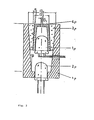
- the optical receiving part which detects at least two angular ranges separately from one another, preferably has a structure which corresponds in principle to the embodiment shown in FIG. 3.
- the device shown in FIG. 3 is characterized by a housing 5p, in the bottom surface of which a light detector 2p is provided centrally, and the inner surface of which, as seen from the light detector 2p, widens conically outwards, one concentrically X on the open side of the housing 5p of the conical surface provided annular glass body 3p, which consists of glass or another translucent material and the inner surface of which, as seen from the light detector 2p, narrows conically outwards, a radiation-impermeable or radiation-impermeable coated sleeve 4p arranged concentrically in the glass body 3p, which at its outward end extends to is closed to a central opening, and a light detector 1p provided concentrically in the sleeve 4p and in the optical axis of the arrangement, the diameter D2 of the central opening of the
- the inner surface of the housing 5p or the outer surface of the glass body 3p and / or the outer surface of the sleeve 4p or the inner surface of the glass body 3p can also advantageously be of parabolic curvature in cross section.
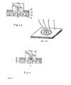
- FIG. 4 shows a further embodiment of the device according to the invention, in which the optical receiving part is designed flat.
- FIG. 4 a shows a sandwich-like arrangement of four layers, of which the bottom layer is a photosensitive layer; layers 2, 3 and 4 can either be light-sensitive or only have a mask function, depending on whether measurements are to be carried out using a two-signal method, a three-signal method or a multi-signal method.
- the variant of the optical receiving part shown in Fig.4a is preferably designed so that the bottom layer is light-sensitive, the second layer 2 above is radiation-opaque and has a central opening in the optical axis with the diameter D1, the third layer 3 above is light-sensitive and has a concentric central opening with the diameter D2, and the fourth layer above it has a central concentric opening with the diameter D3, which acts as an aperture mask.
- the resulting structure is shown schematically in FIG. 4b.
- an uppermost layer 5 made of an opaque material is provided, which has an annular opening with the diameters D2 and D3 and a central opening with the diameter D1 and acts as a mask for the layers 6 and 7 underneath .
- the layer provided under the uppermost layer 5 is light-sensitive and has a central concentric opening, the diameter of which lies between D1 and D2; there is also a light-sensitive layer 7 below it. This arrangement is particularly suitable for the two-signal process.
- the diameters D2 and D3 are selected in the cases of the devices of FIGS. 4a and 4c so that the intended range of scattering angles is detected.
- the devices of FIGS. 4a and 4c Compared to the embodiment of the optical receiving part shown in FIG. 3, the devices of FIGS. 4a and 4c have the advantage of a considerably smaller installation depth; however, these flat receiving parts cannot be constructed using commercially available components.
- the electrical or electronic part of the device according to the invention can be constructed from commercially available components.
- the part that is provided for the intensity control of the light source can, if necessary, be a controller with a special form of the control characteristic, since, for example, laser diodes are known to have a strongly non-linear current-intensity characteristic.
- the signal processing can be carried out both digitally and analogously.
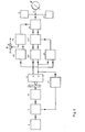
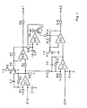
- FIG. 5 shows a basic circuit diagram of the electrical part of a device according to the invention with digital signal processing.
- the arrangement comprises a power supply 8, a control amplifier 9 for the light source, a light source 10 and various light detectors 12 which detect the light transmitted or scattered by the sample 11 and deliver corresponding measurement signals.
- a power supply 8 for the light source
- a light source 10 for the light source
- various light detectors 12 which detect the light transmitted or scattered by the sample 11 and deliver corresponding measurement signals.
- only two light detectors 12 are provided, from whose measurement signals in connection with a reference signal up to a maximum of five signal quantities (two absolute and three relative) can be derived.
- the generation of the relative signal quantities can take place before or after the conversion of the measurement signals into digital signals.
- the measurement signals of the light detectors 12 are amplified by assigned signal amplifiers 13 to 15 and passed via analog-digital converters 22 to a measurement value processing part 1, which can consist of a microprocessor, a microcomputer or another computer.
- a measurement value processing part 1 can consist of a microprocessor, a microcomputer or another computer.
- One or more differential amplifiers 16 or the like provide the relative intensities.
- the measured value processing part generates on the basis of predetermined functions or programs from the measured signal sequence signals that control the signal output, corrects the measured signals by comparison with entered constants and / or in another way, for example by forming differences, forming quotients, addition or subtraction, and also generates the required control variable, which then, for example reaches the control amplifier 9 via the DIA converter 21.
- the measured value processing part 17 may also be designed such that it detects and indicates rising or falling tendencies of the measurement signal or the output signal; the measured value processing part preferably also generates acoustic and / or optical signals with adjustable upper and / or lower limit values, for example warning signals, by means of suitable peripherals.
- the device can also be designed so that it is compatible with other data processing devices and can be connected to other data processing devices.
- the result is output via a display device 18, for example a digital voltmeter, the device further comprises an output device 19 which represents a measured value printer, a recorder or a similar registering and / or indicating instrument and is connected to the measured value processing part 17 via a DIA converter 23.
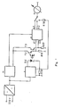
- FIG. 6 shows a block diagram of an embodiment of the electrical part according to the invention, in which the signal processing is carried out analogously.
- the circuit comprises like the circuit shown in FIG. 5 a power supply 8, a control amplifier 9 for the light source, a light source 10 and two light detectors 12 which detect the central beam or the scattered radiation coming from the sample 11.
- the circuit shown in FIG. 6 is designed for the two-signal method; In analog signal processing, methods based on the detection of three or more signals quickly lead to very extensive only two light detectors 12.
- the amplifier 23 ' is controlled by the ratio of the two measured values a / b via the quotient 25 and the amplifier 24 by the difference between the measurement signal a amplified by the amplifier 13 and the voltage which can be set at the resistor R and which is formed by a differential amplifier 16 .
- the measurement signal is correspondingly corrected by the circuit shown in FIG. 6 by amplifier 23 'and absolutely by amplifier 24; the resulting signal is displayed on the display device 18.
- the absolute intensity of the signal b can also be used via a control amplifier 27 to stabilize the intensity of the light source 10.
- the circuit of Figure 6 also includes a limit transmitter 28 which signals an upper and / or lower limit of the signal; (For example, it consists of two Schmitt triggers). The rising or falling tendency of the signal can be derived from the integrator 22 '.
- the circuit also includes an output device 19, i.e. for example a registering and possibly also indicating measuring instrument, e.g. a printer or a writer.
- the circuit of FIG. 6 can also be designed such that it is compatible and can be connected to other, possibly independent data processing devices or systems.
- circuits shown in Figs. 5 and 6 can also be designed so that with the help of the resulting signals, which are displayed by the display device 18 or registered by the output device 19, independent devices such as infusion devices and in particular devices for insulin dosing can optionally also be implantable, can be controlled.
- FIG. 7 shows the basic circuit diagram of a technical embodiment of the device according to the invention, which is based on analog signal processing.
- all functions of the circuit of FIG. 6 are contained with the exception of the control amplifier 27, the limit value transmitter 28 and the output device 19.
- the functions are partially simplified or summarized, the measuring amplifier 30, which is explained in more detail in FIG. 8, the functions of the signal amplifier 13, the integrator 22 ', the amplifiers 23 and 24, the quotient 25 and the differential amplifier 16 of FIG 6 takes over.
- the power supply is based on the mains voltage (e.g. 220 V), which is initially converted into several, for example four, low voltages.
- An alternative power supply from batteries can be provided.
- the circuit has a power supply 29, which supplies the measuring amplifier 30 with a stabilized voltage, for example ⁇ 6 V.
- the two light detectors T2 and T3 are separately supplied by the power supply 29 with a highly stabilized voltage, for example +30 V.
- Resistors R16 and R17 are the signal resistances of light detectors T2 and T3.
- the CW laser diode D5 as a light source is supplied by the power supply with an electronically controlled, also highly stabilized voltage, the power supply being designed in particular in such a way that it also keeps voltage peaks of the mains voltage away from the diode.
- the current of the laser diode D5, which flows through the bypass resistor R18, can, if necessary, be displayed and monitored by the display device 18 with the aid of the series resistor R19.
- the measuring amplifier 30 works both as a differential amplifier and as a single amplifier, as explained in more detail below.
- the measuring amplifier 30 receives the corresponding signals from the light detectors T2 and T3 at its inputs E1 and E2. It has the outputs A1 and A2, which can be connected to the display device 18.
- the measuring amplifier 30 is shown schematically in detail. It forms the difference between the input signals from the signals arriving at inputs E1 and E2 via 1C1 and 1C2 using resistor R11. This difference is sent to output A2 via 1C4 and R15.
- the input signal arriving at E1 is also directly amplified by 1C1 and 1C3 and led to output A1 via R8.
- the gain of the signal channel for the differential signal i.e. the branch E2-IC2-IC4-R15, is regulated depending on the voltage at E1.
- the effectiveness of this control is determined by the resistors R9 and R14 and by the potentiometer P2, which determines the operating point of the operational amplifier 1C4.
- IC5 the voltage at the output of 1C3 is converted via the transistor T1, the diode D4 and the resistor R14 into a control current for the operational amplifier 1C4, whose gain can be regulated.
- the potentiometer P1 is used to set the setpoint for this control, which can be used to set a blood circulation correction on the earlobe, for example, when determining transcutaneous blood glucose.
- the maximum amplification in the signal branch is at least 10,000; an amplification of approximately 1000 is sufficient for the amplification of the branch El-A1.
- this factor is naturally also dependent on the sensitivity of the display instrument.
- the operating points of the operational amplifiers are determined by the following resistances, whereby these also determine the gain: for IC 1 of RI and R2, for IC 3 of R5, R6 and R7, for IC 2 of R10 and R12, for IC 4 besides P 2 also of R13.
- the usual offset zero potentiometers and capacitors for frequency compensation are not shown in the figure.
- the capacitors C1 and C4 serve to reduce the input interference voltages.
- the capacitors C2, C3 and C5 reduce the tendency of the amplifier to oscillate and at the same time serve to integrate the respective signal.
- FIG. 9 shows a device according to the invention for transcutaneous blood glucose determination in vivo on the earlobe, FIG. 9a showing the basic structure of the device and FIG. 9b correspondingly realizing a device to be worn on the body.
- the measurement setup is shown with solid lines; the dashed lines correspond to decorative elements.
- the device is designed as an ear clip, the laser diode D being provided in a cooling block K, which, however, is not absolutely necessary.
- the device also has a deflecting mirror U, which deflects the light emitted by the laser diode by approximately 90 °, so that it passes through the earlobe inserted into the ear clip; the optical receiving part E receives the laser light passing through or scattered through the earlobe, up to 4 or more signals being able to be detected separately from one another.
- the optical receiving part E is in the sandwich technology explained above or approximately in the form of the light pipe arrangement shown in FIG. 3 (cf. Light-pipe cone, in: DE Williamson, Cone Channel Condensor Optics, J. Opt. Soc. Amer.
- the optical receiving part E and the part of the device with the light source also have corresponding electrical supply lines or connecting lines to the current source and, if appropriate, to the signal processing device.
- the optical part is provided in a U-shaped carrier T, which has a resilient joint G in the base area, between the side parts of which an earlobe can be inserted.
- the external design of the device according to the invention shown in FIG. 9a can be chosen freely and is only determined by design considerations, so that it can be adapted to the individual taste of the wearer of the device.
- FIG. 9b The design of the device, indicated by dashed lines in FIG. 9a, is shown in FIG. 9b using a photograph of a specific embodiment. Similar to a conventional ear clip, the device is attached to the earlobe by a simple folding mechanism, the device preferably being made as light and small as possible.
- the power supply for the light source and the signal processing device are preferably provided independently of the ear clip-type actual measuring device and for example at a suitable location, e.g. carried in a bag or under clothing.
- Parts of the device according to the invention, e.g. the output device 19 or the display device 18 can also be designed, for example, in the form of a wristwatch or wristwatch-like device or, for example, a necklace-like device similar to a shoulder clock.
- a paper sample with a thickness such that the resulting mean intensity is equal to that of a biological sample leads to a value for the constant a of 0.19 and for the constant b of 1.15.
- the constants a and b result from an easily feasible curve fitting with pairs of values of the above-mentioned measured variables when measuring several intensities.
- the constants d and e must be determined once for each sample; Surprisingly, however, it has been found that they differ only slightly from sample to sample.
- the measurement correction when measuring biological samples for example with regard to the correction due to changing blood flow to the earlobe must take into account that the effective sample thickness x changes. It can therefore not be carried out simply by forming a ratio, as is possible, for example, with conventional optical two-beam methods.
- the ratio formation provides independence from the absolute intensity, but does not compensate for variable sample thickness.
- the correction function for example to correct different blood flow, must generally have an exponential form.
- the device advantageously has a temperature sensor for measuring the skin temperature at or near the measuring point, the signal of which is used to correct the measuring signals in the signal processing device.
- the measuring device is unchanged at a certain measuring point in all measurements or can be attached in a reproducible manner.
- Such a definition is particularly easy for female users of the ear clip shown in FIG. 9 who have pierced earlobes for jewelry purposes if the measuring device is inserted into the hole in the earlobe.
- the device according to the principle of FIG. 9 therefore advantageously has a corresponding mandrel for such applications, which is inserted through the hole in the earlobe.
- FIG. 10 shows experimental results of a continuous transcutaneous blood glucose measurement carried out with a device according to the invention, a device similar to that of FIG. 9 being used.
- the measurements were carried out on a healthy test subject who, at the start of the experiment, used oral 400 ml of Dextro OG-T to generate a glucose load. were administered.
- Dextro OG-T. solution for oral glucose exposure corresponds to a physiological amount of 100 g anhydrous Glucose.
- 400 ml of juice contain 17 g of anhydrous glucose, 13 g of maltose, 11 g of maltotriose and 53 g of higher oligosaccharides. After hydrolysis in the intestinal tract, this mixture corresponds to the amount of glucose specified above (BM Toleranz-Test, Boehringer Mannheim GmbH, 6800 Mannheim 31).
- the device in the form of an ear clip was attached to the subject's earlobe.
- the device worked according to the two-signal method, with the absolute intensity of the central beam being used for correction.
- the resulting difference signal of the two measurement signals was generated by the signal processing device and recorded with a recorder.
- the method according to the invention and the device according to the invention are particularly suitable due to their underlying technical concept for miniaturization, which can go by orders of magnitude more than the embodiment shown in FIG. 9, micro-miniaturization and consequently also the possibilities of designing implantable devices. are already technically realistic today.
- the method according to the invention and the device according to the invention are not limited to the quantitative determination of glucose in aqueous and, in particular, biological systems, since with a suitable selection of the scattering angle ranges, other dissolved low-molecular and also high-molecular substances can be determined quantitatively in simple and composite systems in principle in the same way .
- the device according to the invention can also be modified to a very large extent within the framework of the inventive concept on the basis of the general technical concept on which it is based.
- the method according to the invention and the device according to the invention thus represent a completely new alternative to previous methods and devices for determining blood glucose as well as for the transcutaneous determination of other blood components and blood values (erythrocyte number, Hb value and the like).
Abstract
Description
Die Erfindung betrifft ein Verfahren sowie eine hochempfindliche Vorrichtung zur quantitativen Bestimmung gelöster niedermolekularer und hochmolekularer Substanzen, besonders von Glucose, in mehrkomponentigen wäßrigen und nichtwäßrigen Lösungen und insbesondere in biologischen Systemen in vitro und in vivo an bzw. in lebenden Organismen durch Lichtstreung.The invention relates to a method and a highly sensitive device for the quantitative determination of dissolved low-molecular and high-molecular substances, especially glucose, in multi-component aqueous and non-aqueous solutions and in particular in biological systems in vitro and in vivo on or in living organisms by light scattering.
Die Erfindung beruht auf dem physikalischen Prinzip der Lichtstreuung. Es ist bekannt, daß durch Wechselwirkung z.B. eines monochromatischen Lichtstrahls mit einem Molekül eine von Art und Struktur des Moleküls abhängige Lichtstreuung auftritt. In einem Mehrkomponentensystem z.B. einem biologischen System wie etwa dem menschlichen Blut, sind jedoch sehr viele verschiedene Moleküle unterschiedlicher Größe enthalten, so daß von vornherein eine selektive Bestimmung nur einer Komponente, z.B. der Glucose, durch Lichtstreuung nicht möglich erscheint.The invention is based on the physical principle of light scattering. It is known that by interaction e.g. of a monochromatic light beam with a molecule, a light scatter depends on the type and structure of the molecule. In a multi-component system e.g. a biological system such as human blood, however, contains many different molecules of different sizes, so that a selective determination of only one component, e.g. the glucose, not possible due to light scattering.
Aus der US-A-3 310 680 ist bereits ein Streulicht-Photometer bekannt, das zur Bestimmung der Konzentration kolloidaler Lösungen vorgesehen ist, wobei die Streulichtintensität in einem vorgegebenen Winkelbereich sowie die Zentralstrahlintensität gemessen werden, und mit einem Quotientenbildner das Verhältnis der entsprechenden beiden Meßsignale gebildet wird, das der Konzentration des Kolloids proportional ist. Diese Vorrichtung eignet sich nicht zur Konzentrationsbestimmung bestimmter Komponenten in Systemen mit mehreren zu bestimmenden Komponenten, insbesondere der der vorliegenden Erfindung zugrundeliegenden Art. Entsprechend ist auch eine Verwendbarkeit zur Konzentrationsbestimmung niedermolekularer oder hochmolekularer gelöster Substanzen in Mehrkomponentensystemen nicht angesprochen.From US-A-3 310 680 a scattered light photometer is already known, which is provided for determining the concentration of colloidal solutions, the scattered light intensity being measured in a predetermined angular range and the central beam intensity, and the ratio of the corresponding two measurement signals using a quotient generator is formed, which is proportional to the concentration of the colloid. This device is not suitable for determining the concentration of certain components in systems with a plurality of components to be determined, in particular of the type on which the present invention is based. Accordingly, a usability for determining the concentration of low-molecular or high-molecular dissolved substances in multicomponent systems is also not addressed.
Der Erfindung liegt die Aufgabe zugrunde, ein Verfahren sowie eine hochempfindliche Vorrichtung zur quantitativen Bestimmung gelöster niedermolekularer sowie hochmolekularer Substanzen, wie etwa von Proteinen, sowie von Blutkörperchen und Blutzellen, insbesondere von Glucose in mehrkomponentigen wäßrigen und nichtwäßrigen Lösungen und besonders in biologischen Systemen in vitro und in vivo an bzw. in lebenden Organismen anzugeben, wobei eine selektive und quantitative Bestimmung einer oder mehrerer bestimmter nieder- oder Hochmolekularer Substanzen oder von Blutkörperchen bzw. Blutzellen auch in Gegenwart anderer gelöster bzw. disperser Substanzen möglich sein soll.The invention has for its object a method and a highly sensitive device for the quantitative determination of dissolved low and high molecular substances, such as proteins, as well as blood cells and blood cells, in particular glucose in multicomponent aqueous and non-aqueous solutions and especially in biological systems in vitro and Specify in vivo on or in living organisms, a selective and quantitative determination of one or more specific low or high molecular weight substances or of blood cells or blood cells should also be possible in the presence of other dissolved or dispersed substances.
Die Aufgabe wird nach den kennzeichnenden Merkmalen der Ansprüche 1 und 15 gelöst.The object is achieved according to the characterizing features of
Das erfindungsgemäße Verfahren erlaubt die quantitative Bestimmung der Konzentration niedermolekularer und hochmolekularer Substanzen sowie von Blutkörperchen und Blutzellen in Mehrkomponentensystemen, wobei sich die Einzelkomponenten in den Lineardimensionen der Moleküle, ihrer Struktur und/oder Zusammensetzung und/oder in der Molekülmasse hinreichend unterscheiden, durch
- (a) Lichtstreuung an der Probe und Analyse der Streukurvenform unter Ermittlung mindestens eines Streuwinkelbereichs pro zu bestimmende Komponente, in dem die stärkste Abhängigkeit der Intensität der Streustrahlung von der Konzentration der jeweiligen Komponente vorliegt,
- (b) Korrektur der gemessenen Intensität der jeweiligen Streustrahlung mit der gemessenen Intensität des Zentralstrahls
und
- (c) Zuordnung der korrigierten Meßgröße zur Konzentration der zu bestimmenden Komponente.
- (a) light scattering on the sample and analysis of the scatter curve shape while determining at least one scattering angle range per component to be determined, in which the greatest dependence of the intensity of the scattered radiation on the concentration of the respective component is present,
- (b) Correction of the measured intensity of the respective scattered radiation with the measured intensity of the central beam
and
- (c) Allocation of the corrected measured variable to the concentration of the component to be determined.
Die erfindungsgemäße Vorrichtung zur Durchführung dieses Verfahrens geht gattungsgemäß von dem Streulichtphotometer gemäß der US-A 33 10 680 aus und umfaßt
- - eine Lichtquelle,
- - ein Probenteil,
- - einen oder mehrere Lichtdetektoren, welche die Intensität des Zentralstrahls und der Streustrahlung in mindestens einem vorgegebenen Winkelbereich erfassen,
- - eine elektronische Signalverarbeitungseinrichtung zur Korrektur der Meßsignale,
- - eine Stromversorgung
sowie
- - eine Signalanzeigeeinrichtung oder einer Signalausgabevorrichtung,
und ist gekennzeichnet durch
- - einen im Prinzip etwa U-förmigen Träger mit einem in seinem Bodenbereich vorgesehenen Gelenk mit einer Feder, die die beiden Seitenteile des Trägers unter einem Federdruck gegeneinander drückt, und einem derartigen Abstand der beiden Seitenteile voneinander, daß in den Zwischenraum zwischen den beiden Seitenteilen des Trägers ein menschliches Ohrläppchen eingeführt und darin festgehalten werden kann,
- - eine an bzw. in einem Seitenteil des Trägers vorgesehene, gegebenenfalls in einem Kühlblock angeordnete Laserdiode als Lichtquelle,
- - einen über der Laserdiode angebrachten Umlenkspiegel, der das von der Laserdiode emittierte Licht um etwa 90° in etwa waagerechte Richtung umlenkt,
und
- - ein gegenüber dem Umlenkspiegel am anderen Seitenteil des Trägers vorgesehenes optisches Empfangsteil mit mindestens einem Lichtdetektor, das die Intensität des Zentralstrahls und der Streustrahlung des durch das in dem Träger eingeführte Ohrläppchen hindurchgehenden bzw. gestreuten Lichts der Laserdiode in mindestens einem vorgegebenen Winkelbereich erfaßt und entsprechende elektrische Signale liefert,
- - wobei die elektronische Signalverarbeitungseinrichtung, die Signalanzeigeeinrichtung und/oder die Signalausgabeeinrichtung sowie die Stromversorgung jeweils mit dem Träger integriert oder von ihm unabhängig vorgesehen sind,
- - a light source,
- - a sample part,
- one or more light detectors which detect the intensity of the central beam and the scattered radiation in at least a predetermined angular range,
- an electronic signal processing device for correcting the measurement signals,
- - a power supply
such as
- a signal display device or a signal output device,
and is characterized by
- - A in principle approximately U-shaped carrier with a joint provided in its bottom region with a spring which presses the two side parts of the carrier against one another under spring pressure, and such a distance between the two side parts that the gap between the two side parts of the A human earlobe can be inserted and held in place,
- a laser diode provided on or in a side part of the carrier, optionally arranged in a cooling block, as the light source,
- a deflection mirror attached above the laser diode, which deflects the light emitted by the laser diode by approximately 90 ° in an approximately horizontal direction,
and
- - An optical receiving part provided with respect to the deflecting mirror on the other side part of the carrier with at least one light detector which detects the intensity of the central beam and the scattered radiation of the laser diode's light passing through or scattered through the earlobe inserted in the carrier in at least a predetermined angular range and corresponding electrical ones Delivers signals,
- - The electronic signal processing device, the signal display device and / or the Signal output device and the power supply are each integrated with the carrier or are provided independently of it,
Vorteilhafte Weiterbildungen der Erfindung sind in den abhängigen Anspruchen angegeben.Advantageous developments of the invention are specified in the dependent claims.
Aus der EP-AI 30 610 ist ferner ein Polarimeter, insbesondere zur Glucosebestimmung, bekannt, dessen optischer Teil ohrclipartig ausgebildet ist.From EP-
Das erfindungsgemäße Verfahren kann besonders günstig verletzungsfrei an lebenden Organismen an einem geeigneten Körperteil durchgeführt werden, beispielsweise durch transcutane Messung an Hautfalten und insbesondere am Ohrläppchen. Die erfindungsgemäße Vorrichtung ist entsprechend vorzugsweise in miniaturisierter Form ausgebildet und stellt besonders bevorzugt eine ohrclipartige Anordnung dar, mit der beispielsweise die Blutglucosekonzentration verletzungsfrei transcutan in vivo gemessen werden kann.The method according to the invention can be carried out particularly advantageously without injury to living organisms on a suitable part of the body, for example by transcutaneous measurement on skin folds and in particular on the earlobe. The device according to the invention is accordingly preferably designed in a miniaturized form and particularly preferably represents an ear clip-like arrangement with which, for example, the blood glucose concentration can be measured transcutaneously in vivo without injury.
Die Erfindung geht von der überraschenden Feststellung aus, daß entgegen der fachmännischen Erwartung gelöste niedermolekulare sowie hochmolekulare Komponenten wie etwa Proteine und Hämoglobin sowie auch größere Partikel, wie Blutkörperchen bzw. Blutzellen, in Mehrkomponentensystemen und insbesondere in biologischen Systemen durch Laser-Lichtstreuung guantitativ und selektiv bestimmt werden können.The invention is based on the surprising finding that, contrary to the professional expectation, low-molecular and high-molecular components, such as proteins and hemoglobin, as well as larger particles, such as blood cells or blood cells, are determined quantitatively and selectively in multi-component systems and in particular in biological systems by laser light scattering can be.
Das Prinzip des erfindungsgemäßen Verfahrens wird im folgenden unter Bezug auf die Bestimmung von Glucose beispielhaft erläutert.The principle of the method according to the invention is explained below by way of example with reference to the determination of glucose.
Die Größe des Glucosemoleküls liegt zwischen der Große von Ionen wie K+, Na+, Ca2+ udgl. und der Größe von Makromolekülen wie etwa Lipiden, Proteinen udgl.sowie den Blutzellen. Während für die obigen Ionen vor wiegend die Weitwinkelstreuung charakteristisch ist, ist für die Makromoleküle in erster Linie die Kleinwinkelstreuung kennzeichnend. Für in der Größe dazwischen liegende Moleküle wie die Glucose ist ein Streubereich maßgebend, der zwischen der Weitwinkelstreuung und der Kleinwinkelstreuung liegt.The size of the glucose molecule is between the size of ions such as K + , Na + , Ca 2+ and the like. and the size of macromolecules such as lipids, proteins and the like, as well as blood cells. While wide-angle scattering is predominantly characteristic of the above ions, small-angle scattering is primarily characteristic of the macromolecules. For molecules in between, such as glucose, a scattering range is decisive that lies between the wide-angle scattering and the small-angle scattering.
Die Methodik der Lichtstreuungsmessung an kleinen Teilchen ist sowohl für Gase als auch für LLösungen theoretisch bestens untersucht (vgl. H.C. van de Hulst, Light Scattering by Small Particles, John Wiley and Sons, New York, 1957, Ch. Tanford, Physical Chemistry of Macromolecules, John Wiley and Sons, New York, 1961; W. Holzmüller, K. Altenburg, Physik der Kunststoffe, Akademie-Verlag, Berlin, 1961, und E.P. Geiduschek und Holtzer, Advances in Biol. and Med. Phys. 6 (1958) 431); aufgrund der vorhandenen theoretischen Grundlagen muß geprüft werden, ob die jeweiligen Voraussetzungen für den in Frage stehenden Winkelbereich gültig sind.The methodology of measuring light scattering on small particles has been theoretically well investigated for both gases and L solutions (cf. HC van de Hulst, Light Scattering by Small Particles, John Wiley and Sons, New York, 1957, Ch. Tanford, Physical Chemistry of Macromolecules , John Wiley and Sons, New York, 1961; W. Holzmüller, K. Altenburg, Physik der Kunststoffe, Akademie-Verlag, Berlin, 1961, and EP Geiduschek and Holtzer, Advances in Biol. And Med. Phys. 6 (1958) 431); on the basis of the existing theoretical basis, it must be checked whether the respective requirements are valid for the angular range in question.
Das Verhältnis der Streulichtintensität I zur Intensität Io des eingestrahlten Lichts ist
- in dieser Gleichung bedeuten:
- Io = Intensität des eingestrahlten Lichts,
- I = Intensität des Streulichts,
- no = Brechungsindex des Lösungsmittels,
- c = molare Konzentration,
- dn/dc = Änderung des Brechungsindex der Lösung mit der Konzentration,
- M = Molekülmasse des gelösten Stoffs,
- N = Avogadrosche Zahl =

- r = Abstand vom Streuzentrum,
- y = Wellenlänge des eingestrahlten Lichts,
- θ = Winkel in Vorwärtsrichtung, gemessen zum Primärstrahl.
- Üblicherweise wird in der Literatur der sog. Streuvektor S
eingeführt, der definiert ist durch
- in this equation mean:
- I o = intensity of the incident light,
- I = intensity of the scattered light,
- n o = refractive index of the solvent,
- c = molar concentration,
- dn / dc = change in the refractive index of the solution with the concentration,
- M = molecular mass of the solute,
- N = Avogadro number =
- r = distance from the center of scattering,
- y = wavelength of the incident light,
- θ = angle in the forward direction, measured to the primary beam.
- Usually, the so-called scatter vector S
introduced, which is defined by
Bei der Laser-Lichtstreuung ist für die Zentrallinie die exponentielle Näherung sinnvoll:
- ζoVo = Zahl der streuenden Teilchen,
- RD = Streumassenradius
- (vgl.W. Koechner, Solid-State Laser Engineering, Springer-Verlag New York, 1976; R. Beck, W. Englisch, K.Cürs, Table of Laser Lines in Gases and Vapors, Springer-Verlag Berlin, 1976, und H. Kressel, Editor, Topics in Applied Physics, Vol. 39, Semiconductor Devices for Optical Communication, Berlin, Heidelberg, New York, 1980).
- ζ o V o = number of scattering particles,
- R D = spreading mass radius
- (see W. Koechner, Solid-State Laser Engineering, Springer-Verlag New York, 1976; R. Beck, W. Englisch, K.Cürs, Table of Laser Lines in Gases and Vapors, Springer-Verlag Berlin, 1976, and H. Kressel, Editor, Topics in Applied Physics, Vol. 39, Semiconductor Devices for Optical Communication, Berlin, Heidelberg, New York, 1980).
Der Streumassenradius der Zentrallinie ist hier in seiner physikalischen Bedeutung ein Charakteristikum für die Laserlinie und das reine Lösungsmittel (z.B. Wasser). Aus dem Verhältnis der Intensitäten bei s = 0 und beispielsweise s = 0,4 läßt sich der Streumassenradius bestimmen. Für Glucose ergibt sich bei einer Wellenlänge von 0,829 um ein Verhältnis von 47,5:1; hieraus folgt ein Streumassenradius RD von 0,233 µm.The scattering radius of the central line is here a physical characteristic of the laser line and the pure solvent (eg water). The radius of the scattering mass can be determined from the ratio of the intensities at s = 0 and, for example, s = 0.4. For glucose at a wavelength of 0.829 around 47.5: 1; this results in a scattering mass radius R D of 0.233 µm.
Um die gesamte Streustrahlung zu erfassen, müssen die auftretenden Interferenzen durch einen zusätzlichen Term berücksichtigt werden. Für die Interferenzfunktion ergibt sich mit der gleichen Näherung, die bei Gleichung (2) verwendet wurde, folgende Beziehung: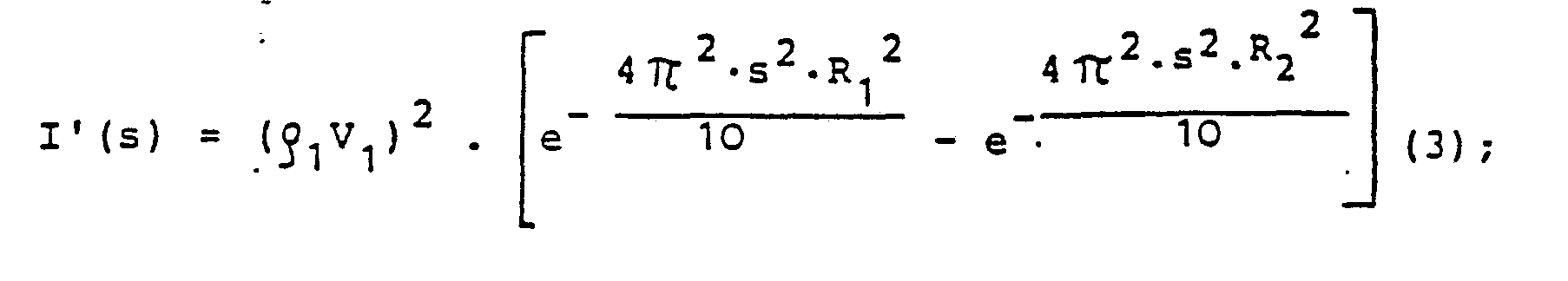
- R1 = innerer Radius der Streuzentren,
- R2 = äußerer Radius der Streuzentren,
- wobei die Streuzonen unterschiedliche Dichte aufweisen.
- R 1 = inner radius of the scattering centers,
- R 2 = outer radius of the scattering centers,
- the scattering zones have different densities.
Die Gesamtintensität setzt sich mit guter Näherung additiv aus den Teilintensitäten zusammen. Da jedoch mit zunehmender Interferenz die Amplitude stets abnimmt, muß I'(s) ein negatives Vorzeichen besitzen. Damit ergibt sich für die gesamte Streuintensität der Lösung die Beziehung
- l(s) = Io(s) - I'(s) (4).
- l (s) = I o (s) - I '(s) (4).
Im Prinzip sind die Konstanten R1 und R2 von der Konzentration der jeweiligen Lösung abhängig. Da diese Abhängigkeit jedoch bei jeder Komponente einer Mehrkomponentenlösung wegen der unterschiedlichen Wechselwirkungen sehr verschieden sein kann, wobei auch Wechselwirkungen von Molekülen unterschiedlicher Art miteinander zu berücksichtigen sind, ist diese Abhängigkeit nur sehr schwer zu ermitteln.In principle, the constants R 1 and R 2 depend on the concentration of the respective solution. However, since this dependency can be very different for each component of a multi-component solution because of the different interactions, and interactions of molecules of different types with one another must also be taken into account, this dependency is very difficult to determine.
Es ist deshalb sinnvoll, den Einfluß der Konzentration der gelösten Substanz, z.B. von Glucose, durch einen formalistischen Produktansatz der Form
- I(s) = Io(s) - F(c) - I'(s) (5)
- zu berücksichtigen, wobei für F(c) folgender Potenzansatz sinnvoll erscheint:
- F(c) = A.cB,
- wobei A und B empirisch zu bestimmende Konstante darstellen.
- I (s) = I o (s) - F (c) - I '(s) (5)
- to be taken into account, whereby the following power approach seems reasonable for F (c):
- F (c) = A.cB,
- where A and B are empirically determinable constants.
Zunächst sollen zur Erläuterung zwei Fälle mit unterschiedlichem Streuverhalten unterschieden werden: 1. Lösungen mit mer einer gelösten Komponenete, die bestimmt werden soll, und 2. Lösungen mit mehreren Komponenten, von denen eine oder mehrere bestimmt werden sollen, z.B. biologische Systeme.First of all, two cases with different scattering behavior are to be differentiated for explanation: 1. Solutions with always one dissolved component that is to be determined, and 2. Solutions with several components, one or more of which are to be determined, e.g. biological systems.
1. Lichstreuung an Lösungen mit nur einer gelösten, zu bestimmenden Komponente, z.B. Lösungen von Glucose in Wasser:
- Aus Formel (1) resultiert Proportionalität der Intensität der Streustrahlung zur Konzentration der streuenden Substanz; diese Proportionalität ist zumindest für niedrige Konzentrationen experimentell zu erwarten, da bei hohen Konzentrationen die Wechselwirkungen der gelösten Moleküle untereinander zu Interferenzerscheinungen führen können (vgl. S. Flügge (Herausgeber) Handbuch der Physik, Band XXXII (Strukturforschung), Prof. Dr. W. W. Beeman, Size of Particles and Lattice Defects, Berlin, Heidelberg, Göttingen, 1957).
- Formula (1) results in proportionality of the intensity of the scattered radiation to the concentration of the scattering substance; this proportionality can be expected experimentally at least for low concentrations, since at high concentrations the interactions of the dissolved molecules with one another can lead to interference phenomena (see S. Flügge (editor) Handbuch der Physik, Volume XXXII (structural research), Prof. Dr. WW Beeman , Size of Particles and Lattice Defects, Berlin, Heidelberg, Göttingen, 1957).
Für Hämoglobinlösungen in Wasser wurde erst im Konzentrationsbereich von 10 % und mehr eine Abnahme der Intensität der Streustrahlung bei einem Streuwinkel von etwa 1° mit steigender Konzentration experimentell festgestellt.For hemoglobin solutions in water there was only a decrease in the concentration range of 10% and more experimentally determined the intensity of the scattered radiation at a scattering angle of approximately 1 ° with increasing concentration.
Für den Fachmann bestand daher bereits für derartige einfachen Systeme keinerlei Erwartungshaltung dafür, daß sich niedermolekulare Substanzen wie etwa Glucose in wäßrigen Lösungen auch bei niedrigen Konzentrationen durch Lichtstreuung quantitativ bestimmen lassen.For simple systems of this type, there was therefore no expectation for the person skilled in the art that low-molecular substances such as glucose in aqueous solutions can be quantified by light scattering, even at low concentrations.
Es ist im Rahmen der Erfindung völlig überraschend, daß sich selbst bei Konzentraticnen von Glucose um 1 % in Wasser bei Verwendung eines He-Ne-Lasers (Leistung etwa 8 mW) als Lichtquelle im Winkelbereich von 0,5 bis 1,5° eine Abnahme der Intensität der Streustrahlung mit der Konzentration ergibt, wobei das Maximun der Intensitätsänderung bei etwa 1,5° liegt.It is completely surprising in the context of the invention that even with concentrates of glucose of 1% in water when using a He-Ne laser (power about 8 mW) as a light source, there is a decrease in the angular range from 0.5 to 1.5 ° of the intensity of the scattered radiation with the concentration, the maximum of the intensity change being about 1.5 °.
Derartige überraschende Meßergebnisse sind in Fig. 1 dargestellt, wo an der Ordinate die Änderung der Intensität mit der Glucosekonzentration und an der Abszisse der Streuwinkel aufgetragen sind.Such surprising measurement results are shown in FIG. 1, where the change in intensity with the glucose concentration is plotted on the ordinate and the scattering angle on the abscissa.
Aus Gleichung (5) ergibt sich für die Änderung der Intensität mit der Glucosekonzentration die Beziehung
-

- mit C = -A. B. cB-1.
-
- with C = -AB cB -1 .
Diese Funktion ist mit den Parametern R, = 3,0 µm, R2 = 3,12 µm und C(ρ1V1/ρoVo)2 = 0,6 in Fig. 1 für eine 1- %ige Lösung von Glucose in Wasser als gestrichelte Linie eingezeichnet. Die Meßergebnisse sind als durchgezogene Kurve eingetragen. Fig. 1 zeigt entsprechend, daß der theoretische Ansatz von Gleichung (6) eine zumindest gualitativ mit der Messung hinsichtlich der Winkellage des Maximums der Intensitätsänderung gute Übereinstimmung liefert.This function is with the parameters R, = 3.0 µm, R 2 = 3.12 µm and C (ρ 1 V 1 / ρ o V o ) 2 = 0.6 in Fig. 1 for a 1% solution of glucose in water as a dashed line. The measurement results are entered as a solid curve. 1 accordingly shows that the theoretical approach of equation (6) provides good correspondence, at least qualitatively, with the measurement with regard to the angular position of the maximum of the intensity change.
Eine bessere Übereinstimmung eines theoretischen Ansatzes mit den in Fig. 1 dargestellten Meßwerten kann durch eine differenziertere Ausarbeitung der Funktion F(c) und/oder durch Untersuchung der Abhängigkeit der Konstanten R, und R2 Von der Konzentration der Lösung erzielt werden.A better agreement of a theoretical approach with the measured values shown in Fig. 1 can be achieved by a more differentiated elaboration of the function F (c) and / or by examining the dependence of the constants R, and R 2 on the concentration of the solution.
Eine mögliche physikalische Interpretation der oben erläuterten überraschenden Lichtstreuerscheinungen in niedrigkonzentrierten Lösungen niedermolekularer Substanzen ist, daß selbst bei kleinen Konzentrationen assoziative Wechselwirkungen zwischen den Glucosemolekülen stattfinden, wobei diese sich zu Assoziaten zusammenlagern und auf diese Weise zu einer Streustrahlung führen, die sich nicht aus den Dimensionen eines Einzelmoleküls ableiten läßt.A possible physical interpretation of the above-mentioned surprising light scattering phenomena in low-concentration solutions of low-molecular substances is that associative interactions take place between the glucose molecules even at small concentrations, whereby these assemble into associations and thus lead to scattered radiation that does not result from the dimensions of one Single molecule can be derived.
Aus den gemessenen Intensitäten bei 1,5° ergibt sich durch Verhältnisbildung aus den Gleichungen (2) und (3) die Beziehung
- hieraus folgt
- n°/

- Dies bedeutet, daß etwa die Hälfte aller Moleküle einen Beitrag zu dieser Streustrahlung leisten.
- 2. Lichtstreuung an Lösungen z.B. biologische Systeme wie Blut:
- it follows from this
- n ° /
- This means that about half of all molecules contribute to this scattered radiation.
- 2. Light scattering on solutions eg biological systems like blood:
Bei solchen Mehrkomponentensystemen und insbesondere biologischen Systemen ist die Wechselwirkung der Moleküle untereinander mit Sicherheit nicht mehr vernachlässigbar. Hierdurch ergibt sich eine zwar nicht grundsätzlich unterschiedliche Form der Streukurve, jedoch ein um Größenordnungen unterschiedliches Verhältnis der Intensitäten bei verschiedenen Streuwinkeln. Während bei einfachen Lösungen etwa beim oben erläuterten Fall 1 ein Intensitätsverhältnis von 0,003 bei einem Streuwinkel von etwa 1,5° vorliegt, sind bei den oben definierten Mehrkomponentensystemen bei gleichem Streuwinkel Intensitäten zu erwarten, deren Verhältnis etwa gleich 1 ist. Theoretisch kann die Intensität des Zentralstrahls unter der Intensität der Streustrahlung bei bestimmten Winkeln liegen (vgl. A. Guinier, X-Ray Diffraction, W. H. Freeman and Company, San Francisco, 1963). In dieser Druckschrift sind die Streuintensitäten als Funktion der Größe VM/Vo untersucht und berechnet, wobei VM das Volumen des betrachteten Moleküls und Vo sein freies Volumen, das umgekehrt proportional zur Konzentration ist, bedeuten. Für VM/Vo = 0 ergibt sich die übliche Form einer Streukurve (Glockenkurvenform), während für VM/Vo) 0,25 die Intensität des Zentralstrahls mit wachsendem Streuwinkel zunächst zunimmt und dann erst abnimmt.In such multicomponent systems and in particular biological systems, the interaction of the molecules with one another is certainly no longer negligible. This results in a shape of the scatter curve that is not fundamentally different, but a ratio of the intensities at different scatter angles that differs by orders of magnitude. While in simple solutions, for example in
Untersucht man nun diese Größe z.B. für Verschiedene Blutkomponenten, so stellt man fest, daß sie bei Glucose den Wert von etwa 10-3 besitzt/ wobei zahlreiche andere Blutkomponenten ähnlich kleine Werte aufweisen, während die Erythrocyten mit 0,4, Proteine mit 0,1 und Hämoglobin mit 0,3 für diese Betrachtungen Werte in einem relevanten Bereich besitzen.If one examines this size, for example for different blood components, one finds that it has the value of about 10- 3 for glucose / whereby numerous other blood components have similarly small values, while the erythrocytes with 0.4, proteins with 0.1 and hemoglobin with 0.3 for these considerations have values in a relevant range.
Für eine Konzentrationsbestimmung im Blut eignen sich daher die Erythrocyten, die Proteine sowie etwa das Hämoglobin, woraus sich erfindungsgemäß eine neuartige transcutane Bestimmung der Erythrocytenzahl, der Hb-Werte udgl. wie auch eine quantitative Bestimmung von Glucose im Blut ergibt, die diese Weise zunächst nicht möglich erschien.The erythrocytes, the proteins and the like are therefore suitable for determining the concentration in the blood Hemoglobin, resulting in a novel transcutaneous determination of the erythrocyte number, the Hb values and the like. as well as a quantitative determination of glucose in the blood, which initially did not appear possible in this way.
Aufgrund der Erfahrungen von Streulichtmessungen bei niedrig konzentrierten Glucoselösungen in Wasser wurde im Rahmen der Erfindung ein Versuch zur Bestimmung der Glucose in mehrkomponentigen Lösungen (wie z.B. Blut) unternommen, der wider Erwarten erfolgreich war.Based on the experience of scattered light measurements with low-concentration glucose solutions in water, an attempt was made within the scope of the invention to determine the glucose in multicomponent solutions (such as blood), which, contrary to expectations, was successful.
Die Erfindung geht also von der völlig überraschenden Feststellung aus, daß auch niedermolekulare Substanzen, wie Glucose, in Mehrkomponentensystemen, wie Blut, durch Laser-Lichtstreuung quantitativ bestimmt werden können.The invention is therefore based on the completely surprising finding that even low-molecular substances, such as glucose, in multicomponent systems, such as blood, can be determined quantitatively by laser light scattering.
Dieser Befund läßt sich theoretisch wie folgt erklären:
- Ändert sich die Konzentration einer niedermolekularen Komponente, wie etwa Glucose im Blut, so ändern sich auch die freien Volumina der übrigen Komponenten und damit die Verhältnisse VMi/V oi (i = 1, 2, 3 ...), wobei die mit i indizierten Komponenten Werte im theoretisch relevanten Bereich 0,1 ≦

- If the concentration of a low molecular weight component, such as glucose in the blood, changes, the free volumes of the other components also change, and with it the ratios VMi / V oi (i = 1, 2, 3 ...), the ones indicated by i Component values in the theoretically relevant range 0.1 ≦
Zur sicheren Identifizierung der zu analysierenden niedermolekularen Komponente, z.B. der Glucose, müssen allerdings noch zusätzliche Informationen herangezogen werden bzw. bestimmte Voraussetzungen erfüllt sein. Dies bedeutet vor allem, daß die Konzentrationen der relevanten Komponenten konstant bleiben müssen. Die Konstanz der Blutzellenkonzentration ist bekannt (Wissenschaftliche Tabellen Geigy, Teilband Hämatologie und Humangenetik, CIBA-GEIGY AG, Basel, 8. Auflage 1979). Eine Beeinflussung des freien Volumens der Blutzellen durch unterschiedliche Glucosekonzentrationen ist jedoch ohnehin wegen des um etwa 7 Größenordnungen verschiedenen Molekül- bzw. Partikelvolumens unwahrscheinlich. Die Proteinkonzentration schwankt andererseits beim Menschen zwischen einem Lebensalter von etwa 20 bis etwa 70 Jahren nur um etwa 2 %, wie ebenfalls aus Wissenschaftliche Tabellen Geigy, Teilband Hämarologie und Humangenetik, CIBA-GEIGY AG, Basel, 8. Auflage, 1979 hervorgeht. Diese Schwankung ist dementsprechend extrem gering. Allerdings sind pathologische Veränderungen bekannt, die erforderlichenfalls überwacht bzw berücksichtigt werden müssen; im Normalfall kann jedoch, beispielsweise auch bei Diabetikern, von einer Konstanz der Proteinkonzentration ausgegangen werden.For reliable identification of the low molecular weight component to be analyzed, e.g. glucose, additional information must be consulted or certain requirements must be met. Above all, this means that the concentrations of the relevant components must remain constant. The constancy of the blood cell concentration is known (scientific tables Geigy, sub-volume hematology and human genetics, CIBA-GEIGY AG, Basel, 8th edition 1979). Anyhow, influencing the free volume of the blood cells by different glucose concentrations is unlikely because of the different molecular or particle volume by about 7 orders of magnitude. The protein concentration on the other hand fluctuates in humans between the ages of about 20 to about 70 years only by about 2%, as is also evident from the Geigy Scientific Tables, Sub-Volume Haematology and Human Genetics, CIBA-GEIGY AG, Basel, 8th edition, 1979. This fluctuation is accordingly extremely small. However, pathological changes are known which, if necessary, must be monitored or taken into account; in normal cases, however, it can be assumed that the protein concentration is constant, for example also in diabetics.
Die Hämoglobinkonzentration wird durch Regulationsmechanismen ebenfalls weitgehend konstantgehalten.The hemoglobin concentration is also kept largely constant by regulatory mechanisms.
Alle übrigen Blutkomponenten können ferner entweder wegen ihrer geringen Konzentration oder wegen ihres geringen Eigenvolumens in Verbindung mit ihrer geringen Konzentration unberücksichtigt bleiben.All other blood components can also be disregarded either because of their low concentration or because of their low intrinsic volume in connection with their low concentration.
Die noch als potentielle Störsubstanzen in Frage kommenden kleinen Ionen Na+, K+ udgl. werden ebenfalls durch sehr empfindliche biologische Regelmechanismen auf konstanter Konzentration gehalten. Erfindungsgemäß kann also die Bestimmung der Konzentration nur einer Komponente in mehrkomponentigen Lösungen, z.B. von Glucose im Blut, unter den oben genannten Voraussetzungen durch Laser-Lichtstreung und Analyse der Form der Streukurve bzw. durch entsprechende Intensitätsmessungen erfolgen, wobei vermutlich für die Meßbarkeit die Veränderung des freien Volumens der relevanten Komponenten verantwortlich ist; diese theoretische Begründung ist allerdings derzeit noch nicht gesichert.The small ions Na +, K + and the like, which are still considered as potential interfering substances. are also kept at a constant concentration by very sensitive biological control mechanisms. According to the invention, the determination of the concentration of only one component in multicomponent solutions, for example of glucose in the blood, can be carried out under the abovementioned conditions by laser light scattering and analysis of the shape of the scatter curve or by corresponding intensity measurements, the change in the presumably for the measurability free volume of the relevant components is responsible; however, this theoretical justification has not yet been confirmed.
Die Messung der Intensität der Streustrahlung zur Analyse der Streukurvenform kann in Vorwärtsrichtung unter einem oder mehreren Streuwinkeln im gesamten Streuwinkelbereich von 0,5 bis 180° erfolgen. Das eingestrahlte Licht ist erfindungsgemäß vorzugsweise linear polarisiert, jedoch kann auch elliptisch polarisiertes, zirkular polarisiertes oder auch unpolarisiertes Licht verwendet werden.The measurement of the intensity of the scattered radiation for analysis of the scatter curve shape can be carried out in the forward direction at one or more scatter angles in the entire scatter angle range from 0.5 to 180 °. According to the invention, the incident light is preferably linearly polarized, but elliptically polarized, circularly polarized or even non-polarized light can also be used.
Bei der transcutanen Messung von Streuintensitäten, d.h. bei der Messung durch Gewebeschichten und 10 Blutgefäße hindurch, liegt ein Teil der Streustrahlung als inkohärente Strahlung vor. Dieser Streustrahlungsanteil wird zwar durch Sekundärstreuung an anderen Schichten stark geschwächt, ist jedoch grundsätzlich nicht vermeidbar. Die inkohärente Streuung kann durch Filter (z.B. Polarisationsfilter) teilweise unterdrückt werden, wenn die Primärstrahlung polarisiert ist. Anderenfalls muß sie als Untergrund vom Signal abgezogen werden.In the transcutaneous measurement of scatter intensities, i.e. when measuring through tissue layers and 10 blood vessels, part of the scattered radiation is present as incoherent radiation. Although this scattered radiation component is greatly weakened by secondary scattering on other layers, it is fundamentally unavoidable. The incoherent scatter can be partially suppressed by filters (e.g. polarization filters) if the primary radiation is polarized. Otherwise it must be subtracted from the signal as a background.
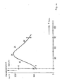
Eine Abschätzung der theoretisch zu erwartenden Änderung der Intensität der Streustrahlung bei einer Änderung der Konzentration einer Komponente ergibt sich aus den Berechnungen von G. Fournet (A. Guinier, X-Ray Diffraction, W. H. Freeman and Company, San Francisco, 1963). Auf dieser Basis ergibt sich für die Abhängigkeit der Intensitätsänderung vom Verhältnis VM/V, das in Fig. 2 dargestellte Bild. An der Ordinate ist die prozentuale Änderung der Streuintensität, bezogen auf die Intensität bei s = 0, und an der Abszisse das Verhältnis der Volumina angetragen. Mit steigender Glucosekonzentration, d.h. fallendem VM/Vo, kann im Streuwinkelbereich um 1° Prinzipiell sowohl eine zunehmende als auch eine abnehmende Signalamplitude erreicht werden, was auch von der Polarität der Teilkomponenten etwa bei einer Differenzbildung abhängt. Außerhalb des Kleinwinkelstreubereichs (z.B. bei θ > 10°) ist jedoch entsprechend Gleichung (1) grundsätzlich eine Zunahme der Intensität der Streustrahlung mit der Konzentration einer niedermolekularen Substanz, z.B. von Glucose, zu erwarten.An estimate of the theoretically expected change in the intensity of the scattered radiation with a change in the concentration of a component results from the calculations by G. Fournet (A. Guinier, X-Ray Diffraction, WH Freeman and Company, San Francisco, 1963). On this basis, the depiction of the change in intensity on the ratio V M / V results in the image shown in FIG. 2. The percentage change in the scattering intensity, based on the intensity at s = 0, is plotted on the ordinate and the ratio of the volumes on the abscissa. With increasing glucose concentration, ie falling V M / V o , in the scattering angle range around 1 ° in principle both an increasing and a decreasing signal amplitude can be achieved, which also depends on the polarity of the subcomponents, for example in the event of a difference. Outside the small-angle scattering range (eg at θ> 10 °), however, an increase in the intensity of the scattered radiation with the concentration of a low-molecular substance, for example of glucose, is generally to be expected according to equation (1).
Die Änderung des freien Volumens insbesondere der Proteine und des Hämoglobins im Fall des Blutes durch eine physiologisch auftretende Änderung der Glucosekonzentration, z.B. bei Diabetikern, von beispielsweise 5 mmol/I auf 15 mmol/I führt zu einer Änderung von VM/Vo um etwa 0,4 im Bereich von 0,2 bis 0,6. Damit ist in erster Näherung eine Intensitätsänderung von 20 % zu erwarten, was ein recht beachtlicher Wert ist. Voraussetzung hierfür ist, daß im Winkelbereich um 1° gemessen wird, was eine sehr gute Meßtechnik erfordert. Bei einer gröberen Meßtechnik daher mit einer wesentlich verringerten Meßempfindlichkeit gerechnet werden.The change in the free volume, in particular of the proteins and of the hemoglobin in the case of blood, due to a physiologically occurring change in the glucose concentration, for example in diabetics, from, for example, 5 mmol / I to 15 mmol / I leads to a change in V M / V o by approximately 0.4 in the range of 0.2 to 0.6. In a first approximation, an intensity change of 20% can be expected, which is a quite remarkable value. The prerequisite for this is that the angle is measured by 1 °, which requires very good measuring technology. In the case of a coarser measuring technique, a significantly reduced measuring sensitivity can therefore be expected.
Eine zusätzliche grundsätzliche Schwierigkeit bei der Messung z.B. von Blutkomponenten durch Laser-Lichtstreuung an einem geeigneten Körperteil, z.B. dem Ohrläppchen, ergibt sich aus dessen wechselnder Durchblutung, was dazu führen kann, daß gänzlich verschiedene Meßsignale bei gleicher Glucosekonzentration erhalten werden. Eine entsprechende Korrektur ist jedoch erfindungsgemäß technisch ohne weiteres möglich. Hierfür wird vorteilhafterweise die Intensität des Zentralstrahls oder das Verhältnis der Intensität des Zentralstrahls zur Intensität der Streustrahlung herangezogen. So wird beispielsweise bei einer fest vorgegebenen Lichtintensität die Intensität des Zentralstrahls gemessen und durch Differenzbildung mit einem individuell vorgebbaren Sollwert eine Korrektur des Meßsignals herbeigeführt, wobei ein empirisch zu bestimmender Vorfaktor benützt werden kann.An additional fundamental difficulty in measuring e.g. blood components by laser light scattering on a suitable part of the body, e.g. the earlobe results from the changing blood flow, which can lead to completely different measurement signals being obtained with the same glucose concentration. A corresponding correction is, however, technically easily possible according to the invention. The intensity of the central beam or the ratio of the intensity of the central beam to the intensity of the scattered radiation is advantageously used for this. For example, the intensity of the central beam is measured at a predetermined light intensity and the measurement signal is corrected by forming a difference with an individually predeterminable target value, an empirically determined pre-factor being able to be used.
Die Messung der Konzentration einer Komponente einer mehrkomponentigen Lösung, z.B. der Glucosekonzentration im Blut, erfolgt erfindungsgemäß, wie oben erläutert und abgeleitet, durch Analyse der Streukurvenform und Ermittlung desjenigen Winkelbereichs der Streustrahlung, in dem die größte Intensitätsänderung in Abhängigkeit von der Konzentration der zu bestimmenden Komponente vorliegt. Am einfachsten kann die Messung erfindungsgemäß nach dem sog. Zweisignalverfahren durchgeführt werden, jedoch ist selbstverständlich auch eine Intensitätsmessung unter kontinuierlicher Änderung des Streuwinkels durchführbar, was jedoch apparativ einen größeren Aufwand erfordert. Beim Zweisignalverfahren wird die Intensität des Zentralstrahls sowie eine Streulichtintensität unter einem bestimmten Streuwinkel gemessen. Der Winkelbereich, innerhalb dessen die Streulichtintensität gemessen wird, wird erfindungsgemäß vorteilhaft so gewählt, daß die Änderung der Intensität der Streustrahlung mit der Änderung der zu messenden Konzentration in diesem Bereich maximal wird.Measuring the concentration of a component of a multi-component solution, e.g. the glucose concentration in the blood is carried out according to the invention, as explained and derived above, by analyzing the scatter curve shape and determining that angular range of the scattered radiation in which the greatest change in intensity is present as a function of the concentration of the component to be determined. According to the invention, the easiest way to carry out the measurement is by the so-called two-signal method, but of course an intensity measurement can also be carried out with a continuous change in the scattering angle, but this requires a greater outlay in terms of apparatus. In the two-signal method, the intensity of the central beam and a scattered light intensity are measured at a certain scattering angle. The angular range within which the scattered light intensity is measured is advantageously selected according to the invention such that the change in the intensity of the scattered radiation becomes maximum with the change in the concentration to be measured in this range.
Die erfindungsgemäße Vorrichtung umfaßt prinzipiell einen optischen Teil, einen elektrischen bzw. elektronischen Teil sowie einen mechanischeh Teil. Sie weist im wesentlichen folgende Bestandteile auf:
- A) Optischer Teil:
- a) Lichtquelle (Laser, Laserdiode)
- b) gegebenenfalls einen Umlenkspiegel (fest oder beweglich)
- c) Probe bzw Probenhalter + Küvette
- d) gegebenenfalls einen Umlenkspiegel (fest oder beweglich)
- e) optisches Empfangsteil mit getrennter Erfassung von mindestens zwei Winkelbereichen, falls die Spiegel
- b) und/oder d) nicht beweglich sind,
und
- f) ein oder mehrere Lichtdetektoren.
- B) Elektrischer Teil:
- a) Stromversorgung für die Lichtguelle, gegebenenfalls steuerbar oder regelbar
- b) Stromversorgung für die Lichtdetektoren
- c) gegebenenfalls Intensitätsregelung für die Lichtquelle
- d) Verstärker für die Signale der Lichtdetektoren der verschiedenen Winkelbereiche, entsprechend der Sektorierung des optischen Empfangsteils
- e) Differenzbildner, Addierglied, Quotientenbildner und/oder Multiplizierer
- f) Signalverarbeitungsteil (Mikroprozessor, Mikrocomputer oder Rechner) mit Speicher, Konstanten, Ein- und Ausgabemöglichkeit
- g) Signalanzeigegerät
- h) Ausgabevorrichtung (Drucker, Schreiber udgl.).
- A) Optical part:
- a) light source (laser, laser diode)
- b) if necessary, a deflecting mirror (fixed or movable)
- c) Sample or sample holder + cuvette
- d) if necessary, a deflecting mirror (fixed or movable)
- e) optical receiving part with separate detection of at least two angular ranges, if the mirror
- b) and / or d) are not movable,
and
- f) one or more light detectors.
- B) Electrical part:
- a) Power supply for the Lichtguelle, possibly controllable or regulatable
- b) Power supply for the light detectors
- c) optionally intensity control for the light source
- d) amplifier for the signals of the light detectors of the different angular ranges, corresponding to the sectoring of the optical receiving part
- e) difference generator, adder, quotient generator and / or multiplier
- f) Signal processing part (microprocessor, microcomputer or computer) with memory, constants, input and output options
- g) signal display device
- h) output device (printer, writer, etc.).
Der mechanische Aufbau hängt vom jeweils vorgesehenen Verwendungszweck ab; der mechanische Teil ist erfindungsgemäß insbesondere als klapp- oder schiebbarer Meßaufbau ausgebildet, der eine feste oder bewegliche Lichtquelle, feste oder bewegliche Umlenkeinrichtungen wie Umlenkspiegel, ein festes oder bewegliches Lichtempfangsteil, vorzugsweise mit Winkelbereichssektorierung, sowie eine Befestigungseinrichtung zur Befestigung an einem geeigneten Körperteil, z.B. am Ohrläppchen, aufweist.The mechanical structure depends on the intended use; the mechanical part is designed according to the invention in particular as a folding or sliding measuring structure, which has a fixed or movable light source, fixed or movable deflection devices such as deflection mirrors, a fixed or movable light receiving part, preferably with angular range sectoring, and a fastening device for fastening to a suitable body part, e.g. on the earlobe.
Zur Messung am Ohr eignet sich besonders eine ohrclipartige Ausführungsform, wobei die erfindungsgemäße Vorrichtung zugleich in Form von üblichem Schmuck augebildet sien kann.An ear clip-like embodiment is particularly suitable for measuring on the ear, and the device according to the invention can also be designed in the form of customary jewelry.
Die einzelnen optischen und elektrischen bzw. elektronischen Komponenten können dabei erfindungsgemäß auf unterschiedliche Vorrichtungsteile verteilt und mit diesen teilweise oder ganz integriert sein. Erfindungsgemäß ist vorzugsweise der elektronische Teil teilweise oder ganz in integrierter Form ausgebildet; vorteilhafterweise kann auch der optische Teil in einer integrierten Form ausgebildet sein.According to the invention, the individual optical and electrical or electronic components can be distributed to different parts of the device and can be partially or completely integrated with them. According to the invention, the electronic part is preferably designed partially or completely in an integrated form; The optical part can advantageously also be formed in an integrated form.
Für die Komponenten des optischen Sendeteils können handelsübliche Bauteile verwendet werden.Commercially available components can be used for the components of the optical transmission part.
Das optische Empfangsteil, das mindestens zwei Winkelbereiche getrennt voneinander erfaßt, besitzt vorzugsweise einen Aufbau, der im Prinzip der in Fig. 3 dargestellten Ausführungsform entspricht. Die in Fig. 3 dargestellte Vorrichtung ist gekennzeichnet durch ein Gehäuse 5p, in dessen Bodenfläche ein Lichtdetektor 2p zentrisch vorgesehen ist, und dessen Innenfläche sich vom Lichtdetektor 2p aus gesehen nach außen konisch erweitert, einen an der offenen Seite des Gehäuses 5p konzentrisch X der Konusfläche vorgesehenen ringförmigen Glaskörper 3p, der aus Glas oder einem anderen-lichtdurchlässigen Material besteht und dessen Innenfläche sich vom Lichtdetektor 2p aus gesehen nach außen konisch verengt, eine im Glaskörper 3p konzentrisch angeordnete strahlungsundurchlässige oder strahlungsundurchlässig beschichtete Hülse 4p, die an ihrem nach außen gerichteten Ende bis auf eine zentrale Öffnung verschlossen ist, und einen in der Hülse 4p konzentrisch und in der optischen Achse der Anordnung vorgesehenen Lichtdetektor 1p, wobei der Durchmesser D2 der zentralen Öffnung der Hülse 4p, der Durchmesser D2 der außen liegenden Bodenfläche der Hülse 4p und der Durchmesser D3 der außen liegenden Bodenfläche des Glaskörpers 3p sowie der Konus-Halbwinkel a der Hülse 4p und der Konus-Halbwinkel β des Gehäuses 5p bzw. des Innenkonus des Glaskörpers 3p so ausgelegt sind, daß die gesamte in den zugrundegelegten Streuwinkelbereich fallende Streustrahlung vom Lichtdetektor 2p erfaßt wird.The optical receiving part, which detects at least two angular ranges separately from one another, preferably has a structure which corresponds in principle to the embodiment shown in FIG. 3. The device shown in FIG. 3 is characterized by a housing 5p, in the bottom surface of which a light detector 2p is provided centrally, and the inner surface of which, as seen from the light detector 2p, widens conically outwards, one concentrically X on the open side of the housing 5p of the conical surface provided annular glass body 3p, which consists of glass or another translucent material and the inner surface of which, as seen from the light detector 2p, narrows conically outwards, a radiation-impermeable or radiation-impermeable coated sleeve 4p arranged concentrically in the glass body 3p, which at its outward end extends to is closed to a central opening, and a light detector 1p provided concentrically in the sleeve 4p and in the optical axis of the arrangement, the diameter D2 of the central opening of the sleeve 4p and the diameter D2 of the outer bottom surface the sleeve 4p and the diameter D3 of the outer bottom surface of the glass body 3p and the cone half angle a of the sleeve 4p and the cone half angle β of the housing 5p and the inner cone of the glass body 3p are designed so that the entire in the underlying scattering angle range falling scattered radiation is detected by the light detector 2p.
Die Innenfläche des Gehäuses 5p bzw. die Außenfläche des Glaskörpers 3p und/oder die Außenfläche der Hülse 4p bzw die Innenfläche des Glaskörpers 3p können auch vorteilhafterweise im Querschnitt parabelförmig gekrümmt ausgebildet sein.The inner surface of the housing 5p or the outer surface of the glass body 3p and / or the outer surface of the sleeve 4p or the inner surface of the glass body 3p can also advantageously be of parabolic curvature in cross section.
In Fig. 4 ist eine weitere Ausführungsform der erfindungsgemäßen Vorrichtung dargestellt, bei der der optische Empfangsteil flach ausgebildet ist. In Fig.4a ist eine sandwichartige Anordnung von vier Schichten dargestellt, von denen die unterste Schicht eine lichtempfindliche Schicht ist; die Schichten 2, 3 und 4 können entweder lichtempfindlich sein oder lediglich Maskenfunktion besitzen, je nachdem, ob nach einem Zweisignalverfahren, einem Dreisignalverfahren oder einem Mehrsignalverfahren gemessen werden soll. Die in Fig.4a dargestellte Variante des optischen Empfangsteils ist vorzugsweise so ausgebildet, daß die unterste Schicht lichtempfindlich ist, die darüberliegende zweite Schicht 2 strahlungsundurchlässig ist und eine in der optischen Achse liegende zentrale Öffnung mit dem Durchmesser D1 aufweist, die darüberliegende dritte Schicht 3 lichtempfindlich ist und eine konzentrische zentrale Öffnung mit dem Durchmesser D2 aufweist, und die darüberliegende vierte Schichte eine zentrale konzentrische Öffnung mit dem Durchmesser D3 besitzt, die als Blendenmaske wirkt.4 shows a further embodiment of the device according to the invention, in which the optical receiving part is designed flat. FIG. 4 a shows a sandwich-like arrangement of four layers, of which the bottom layer is a photosensitive layer;
In Fig. 4b ist die resultierende Struktur schematisch dargestellt.The resulting structure is shown schematically in FIG. 4b.
Eine weitere erfindungsgemäße Ausführungsform zeigt Fig. 4c. Bei dieser Variante des ebenfalls flach ausgebildeten optischen Empfangsteils ist eine oberste Schicht 5 aus einem lichtundurchlässigen Material vorgesehen, die eine ringförmige Öffnung mit den Durchmessern D2 und D3 und eine zentrale Öffnung mit dem Durchmesser D1 aufweist und als Maske für die darunterliegenden Schichten 6 und 7 wirkt. Die unter der obersten Schicht 5 vorgesehene Schicht Ist lichtempfindlich und weist eine zentrale konzentrische Öffnung auf, deren Durchmesser zwischen D1 und D2 liegt; unter ihr befindet sich eine ebenfalls lichtempfindliche Schicht 7. Diese Anordnung eignet sich speziell für das Zweisignalverfahren.4c shows a further embodiment according to the invention. In this variant of the likewise flat optical receiving part, an
Die Durchmesser D2 und D3 werden in den Fällen der Vorrichtungen der Fig. 4a und 4c so gewählt, daß der vorgesehene Streuwinkelbereich erfaßt wird.The diameters D2 and D3 are selected in the cases of the devices of FIGS. 4a and 4c so that the intended range of scattering angles is detected.
Gegenüber der in Fig. 3 dargestellten Ausführungsform des optischen Empfangsteils haben die Vorrichtungen der Fig. 4a und 4c den Vorteil einer erheblich geringeren Einbautiefe; diese flachen Empfangsteile können jedoch nicht mit handelsüblichen Bauelementen aufgebaut werden.Compared to the embodiment of the optical receiving part shown in FIG. 3, the devices of FIGS. 4a and 4c have the advantage of a considerably smaller installation depth; however, these flat receiving parts cannot be constructed using commercially available components.
Der elektrische bzw elektronische Teil der erfindungsgemäßen Vorrichtung kann aus handelsüblichen Bauelementen aufgebaut sein. Derjenige Teil, der zur Intensitätsregelung der Lichtguelle vorgesehen ist, kann erforderlichenfalls ein Regler mit einer speziellen Form der Regelkennlinie sein, da beispielsweise Laserdioden bekanntermaßen eine stark nichtlineare Strom-Intensitäts-Charakteristik aufweisen.The electrical or electronic part of the device according to the invention can be constructed from commercially available components. The part that is provided for the intensity control of the light source can, if necessary, be a controller with a special form of the control characteristic, since, for example, laser diodes are known to have a strongly non-linear current-intensity characteristic.
Die Signalverarbeitung kann erfindungsgemäß sowohl digital als auch analog vorgenommen werden.According to the invention, the signal processing can be carried out both digitally and analogously.
In Fig. 5 ist ein Prinzipschaltbild des elektrischen Teils einer erfindungsgemäßen Vorrichtung mit digitaler Signalverarbeitung dargestellt. Die Anordnung umfaßt eine Stromversorgung 8, einen Regelverstärker 9 für die Lichtquelle, eine Lichtquelle 10 sowie verschiedene Lichtdetektoren 12, die das von der Probe 11 durchgelassene bzw.gestreute Licht erfassen und entsprechende Meßsignale liefern. Im einfachsten Fall sind nur zwei Lichtdetektoren 12 vorgesehen, aus deren Meßsignalen in Verbindung mit einem Referenzsignal bis zu maximal fünf Signalgrößen (zwei absolute und drei relative) abgeleitet werden können. Die Erzeugung der relativen Signalgrößen kann dabei vor oder nach der Umwandlung der Meßsignale in digitale Signale erfolgen.5 shows a basic circuit diagram of the electrical part of a device according to the invention with digital signal processing. The arrangement comprises a
Die Meßsignale der Lichtdetektoren 12 werden durch zugeordnete Signalverstärker 13 bis 15 verstärkt und über Analog-Digital-Wandler 22 zu einem Meßwertverarbeitungsteil 1 geleitet, das aus einem Mikroprozessor, einem Mikrocomputer oder einem sonstigen Rechner bestehen kann. Ein oder mehrere Differenzverstärker 16 oder dergleichen, liefern die relativen Intensitäten. Das Meßwertverarbeitungsteil erzeugt aufgrund vorgegebener Funktionen bzw. Programme aus den Meßsignalensusgangssignale, welche die Signalausgabe steuern, korrigiert die Meßsignale durch Vergleich mit eingegebenen Konstanten und/ oder in anderer Weise, beispielsweise durch Differenzbildung, Quotientenbildung, Addition oder Subtraktion, und erzeugt ferner die erforderliche Regelgröße, die dann z.B. über DIA-Wandler 21 zum Regelverstärker 9 gelangt. Das Meßwertverarbeitungsteil 17 ist ferner gegebenenfalls so ausgebildet, daß es steigende oder fallende Tendenzen des Meßsignals bzw. des ausgegebenen Signals erkennt und anzeigt; das Meßwertverarbeitungsteil erzeugt ferner vorzugsweise durch eine geeignete Peripherie akustische und/oder optische Signale bei einstellbaren oberen und/oder unteren Grenzwerten, beispielsweise Warnsignale. Die Vorrichtung kann weiter so ausgelegt sein, daß sie mit anderen Datenverarbeitungseinrichtungen kompatibel ist und an andere Datenverarbeitungseinrichtungen angeschlossen werden kann. Die Ergebnisausgabe erfolgt über eine Anzeige einrichtung 18, beispielsweise ein Digitalvoltmeter die Vorrichtung umfaßt ferner eine Ausgabeeinrichtung 19, die einen Meßwertdrucker, einen Schreiber oder ein ähnliches registrierendes und/oder anzeigendes Instrument darstellt und über einen DIA-Wandler 23 am Meßwertverarbeitungsteil 17 angeschlossen ist.The measurement signals of the
In Fig. 6 ist ein Blockschaltbild einer erfindungsgemäßen Ausführungsform des elektrischen Teils dargestellt, bei der die Signalverarbeitung analog erfolgt. Die Schaltung umfaßt wie die in Fig. 5 dargestellte Schaltung eine Stromversorgung 8, einen Regelverstärker 9 für die Lichtguelle, eine Lichtguelle 10 und zwei Lichtdetektoren 12, die den Zentralstrahl bzw.die von der Probe 11 kommende Streustrahlung erfassen.6 shows a block diagram of an embodiment of the electrical part according to the invention, in which the signal processing is carried out analogously. The circuit comprises like the circuit shown in FIG. 5 a
Die in Fig. 6 dargestellte Schaltung ist für das Zweisignalverfahren ausgelegt; Verfahren, die auf der Erfassung von drei oder mehr Signalen beruhen,führen bei analoger Signalverarbeitung rasch zu sehr umfangchend nur zwei Lichtdetektoren 12 auf.The circuit shown in FIG. 6 is designed for the two-signal method; In analog signal processing, methods based on the detection of three or more signals quickly lead to very extensive only two
Die Vorrichtung umfaßt ferner einen Differenzverstärker mit Integrator 22', der das Differenzsignal der Signale a und b der Lichtdetektoren 12 integriert (Zeitkonstante τ = 1 bis 10 s); das resultierende Signal wird in den Verstärkern 23' und 24 nochmals verstärkt und mit einer Anzeigeeinrichtung 18 angezeigt. Der Verstärker 23' wird dabei durch das Verhältnis der beiden Meßwerte a/b über den Quotientenbildner 25 und der Verstärker 24 durch die Differenz des durch den Verstärker 13 verstärkten Meßsignals a und der am Widerstand R einstellbaren Spannung die durch einen Differenzverstärker 16 gebildet wird, gesteuert. Das Meßsignal wird durch die in Fig. 6 dargestellte Schaltung entsprechend durch den Verstärker 23' relativ und durch den Verstärker 24 absolut korrigiert; das resultierende Signal wird mit der Anzeigeeinrichtung 18 angezeigt.The device further comprises a differential amplifier with integrator 22 ', which integrates the difference signal of signals a and b from light detectors 12 (time constant τ = 1 to 10 s); the resulting signal is amplified again in the
Die Absolutintensität des Signals b kann ferner erforderlichenfalls über einen Regelverstärker 27 zur Stabilisierung der Intensität der Lichtquelle 10 herangezogen werden. Die Schaltung von Fig.6 umfaßt ferner einen Grenzwertgeber 28, der einen oberen und/oder unteren Grenzwert des Signals signalisiert; (er besteht beispielsweise aus zwei Schmitt-Triggern). Die steigende oder fallende Tendenz des Signals kann vom Integrator 22' abgeleitet werden. Die Schaltung umfaßt schließlich auch eine Ausgabeeinrichtung 19, d.h. beispielsweise ein registrierendes und gegebenenfalls auch anzeigendes Meßinstrument, z.B. einen Drucker oder einen Schreiber.If necessary, the absolute intensity of the signal b can also be used via a
Auch die Schaltung von Fig. 6 kann ferner so ausgelegt sein, daß sie mit anderen, gegebenenfalls unabhängigen Datenverarbeitungseinrichtungen oder -anlagen kompatibel ist und verbunden werden kann.The circuit of FIG. 6 can also be designed such that it is compatible and can be connected to other, possibly independent data processing devices or systems.
Die in den Fig. 5 und 6 dargestellten Schaltungen können ferner auch so ausgelegt sein, daß mit Hilfe der resultierenden Signale, die von der Anzeigeeinrichtung 18 angezeigt oder von der Ausgabeeinrichtung 19 registriert werden, unabhängige Geräte wie beispielsweise Infusionseinrichtungen und insbesondere Vorrichtungen zur Insulindosierung, die gegebenenfalls auch implantierbar sein können, angesteuert werden können.The circuits shown in Figs. 5 and 6 can also be designed so that with the help of the resulting signals, which are displayed by the
In Fig. 7 ist das Prinzipschaltbild einer technischen Ausführungsform der erfindungsgemäßen Vorrichtung dargestellt, die auf der analogen Signalverarbeitung beruht. Auch in dieser Ausführungsform sind alle Funktionen der Schaltung von Fig. 6 mit Ausnahme des Regelverstärkers 27, des Grenzwertgebers 28 und der Ausgabeeinrichtung 19 enthalten. Die Funktionen sind jedoch teilweise vereinfacht bzw. zusammengefaßt, wobei der Meßverstärker 30, der bei Fig. 8 näher erläutert ist, die Funktionen des Signalverstärkers 13, des Integrators 22', der Verstärker 23 und 24, des Quotientenbildners 25 und des Differenzverstärkers 16 von Fig. 6 übernimmt.7 shows the basic circuit diagram of a technical embodiment of the device according to the invention, which is based on analog signal processing. In this embodiment too, all functions of the circuit of FIG. 6 are contained with the exception of the
Zur Stromversorgung wird von der Netzspannung, (z.B. 220 V) ausgegangen, die zunächst in mehrere, beispielsweise vier Niederspannungen umgesetzt wird. Eine alternative Stromversorgung durch Batterien kann vorgesehen sein. Die Schaltung weist eine Stromversorgung 29 auf, die den Meßverstärker 30 mit einer stabilisierten Spannung, beispielsweise ± 6 V, versorgt. Ferner werden die beiden Lichtdetektoren T2 und T3 getrennt davon durch die Stromversorgung 29 mit einer hochstabilisierten Spannung, zB +30 V, versorgt. Die Widerstände R16 und R17 sind die Signalwiderstände der Lichtdetektoren T2 und T3. Die CW-Laserdiode D5 als Lichtquelle wird von der Stromversorgung mit einer elektronisch geregelten, ebenfalls hochstabilisierten Spannung versorgt, wobei die Stromversorgung insbesondere so ausgelegt ist, daß sie auch Spannungsspitzen der Netzspannung in jedem Fall von der Diode fernhält. Der Strom der Laserdiode D5, der über den Bypass-Widerstand R18 fließt, kann mit Hilfe des Serienwiderstands R19 erforderlichenfalls durch die Anzeigeeinrichtung 18 angezeigt und überwacht werden. Der Meßverstärker 30 arbeitet sowohl als Differenzverstärker als auch als Einzelverstärker, wie im folgenden näher erläutert ist.The power supply is based on the mains voltage (e.g. 220 V), which is initially converted into several, for example four, low voltages. An alternative power supply from batteries can be provided. The circuit has a
Der Meßverstärker 30 erhält an seinen Eingängen E1 und E2 die entsprechenden Signale der Lichtdetektoren T2 bzw T3 zugeführt. Er besitzt die Ausgänge A1 und A2, die mit der Anzeigeeinrichtung 18 verbunden werden können.The measuring
In Fig. 8 ist der Meßverstärker 30 im einzelnen schematisch dargestellt. Er bildet aus den an den Eingängen E1 und E2 ankommenden Signalen über 1C1 und 1C2 mit Hilfe des Widerstands R11 die Differenz der Eingangssignale. Diese Differenz wird über 1C4 und R15 zum Ausgang A2 geleitet. Das an E1 ankommende Eingangssignal wird ferner durch 1C1 und 1C3 auch direkt verstärkt und über R8 zum Ausgang A1 geführt.8, the measuring
Die Verstärkung des Signalkanals für das Differenzsignal, also des Zweiges E2-IC2-IC4-R15, wird in Abhängigkeit von der Spannung an E1 geregelt. Die Wirksamkeit dieser Regelung wird durch die Widerstände R9 und R14 sowie durch das Potentiometer P2 bestimmt, das den Arbeitspunkt des Operationsverstärkers 1C4 festlegt. Mit IC5 wird über den Transistor T1, die Diode D4 und den Widerstand R14 die Spannung am Ausgang von 1C3 in einen Steuerstrom für den in seiner Verstärkung regelbaren Operationsverstärker 1C4 umgewandelt. Das Potentiometer P1 dient zur Sollwerteinstellung für diese Steuerung, mit der sich beispielsweise bei der transcutanen Blutglucosebestimmung am Ohrläppchen eine Durchblutungskorrektur einstellen läßt.The gain of the signal channel for the differential signal, i.e. the branch E2-IC2-IC4-R15, is regulated depending on the voltage at E1. The effectiveness of this control is determined by the resistors R9 and R14 and by the potentiometer P2, which determines the operating point of the operational amplifier 1C4. With IC5, the voltage at the output of 1C3 is converted via the transistor T1, the diode D4 and the resistor R14 into a control current for the operational amplifier 1C4, whose gain can be regulated. The potentiometer P1 is used to set the setpoint for this control, which can be used to set a blood circulation correction on the earlobe, for example, when determining transcutaneous blood glucose.
Die maximale Verstärkung im Signalzweig beträgt mindestens 10000, für die Verstärkung des Zweigs El - A1 ist eine Verstärkung von etwa 1000 ausreichend. Dieser Faktor ist aber naturgemäß auch noch von der Empfindlichkeit des Anzeigeinstruments abhängig.The maximum amplification in the signal branch is at least 10,000; an amplification of approximately 1000 is sufficient for the amplification of the branch El-A1. However, this factor is naturally also dependent on the sensitivity of the display instrument.
Die Arbeitspunkte der Operationsverstärker werden durch die folgenden Widerstände bestimmt, wobei diese auch die Verstärkung bestimmen: bei IC 1 von RI und R2, bei IC 3 von R5, R6 und R7, bei IC 2 von R10 und R12, bei IC 4 außer von P 2 auch von R13. Außerdem sind die üblichen, in der Figur nicht wiedergegebenen Offset-Null-Potentiometer und Kondensatoren zur Freguenzkompensation vorgesehen. Die Kondensatoren C1 und C4 dienen zur Senkung der Eingangsstörspannungen. Die Kondensatoren C2, C3 und C5 verringern die Schwingneigung des Verstärkers und dienen gleichzeitig zur Integration des jeweiligen Signals.The operating points of the operational amplifiers are determined by the following resistances, whereby these also determine the gain: for
In Fig. 9 ist eine zur transcutanen Blutglucosebestimmung in vivo am Ohrläppchen vorgesehene erfindungsgemäße Vorrichtung dargestellt, wobei Fig. 9a den prinzipiellen Aufbau der Vorrichtung und Fig. 9b eine entsprechende Realisierung einer am Körper zu tragenden Vorrichtung zeigen.FIG. 9 shows a device according to the invention for transcutaneous blood glucose determination in vivo on the earlobe, FIG. 9a showing the basic structure of the device and FIG. 9b correspondingly realizing a device to be worn on the body.
Der Meßaufbau ist mit durchgezogenen Strichen dargestellt; die gestrichelten Linien entsprechen dekorativen Elementen.The measurement setup is shown with solid lines; the dashed lines correspond to decorative elements.
Die Vorrichtung ist als Ohrclip ausgeführt, wobei die Laserdiode D in einem Kühlblock K vorgesehen ist, der jedoch nicht zwingend erforderlich ist. Die Vorrichtung weist ferner einen Umlenkspiegel U auf, der das von der Laserdiode emittierte Licht um etwa 90° umlenkt, so daß es durch das in den Ohrclip eingeführte Ohrläppchen hindurchgeht; der optische Empfangsteil E empfängt das durch das Ohrläppchen hindurchgehende bzw.gestreute Laserlicht, wobei bis zu 4 oder auch mehr Signale getrennt voneinander erfaßt werden können. Das optische Empfangsteil E ist in der oben erläuterten Sandwichtechnik oder etwa in Form der in Fig. 3 dargestellten Lichtpfeifenanordnung (vgl. Light-pipe cone, in: D.E. Williamson, Cone Channel Condensor Optics, J. Opt. Soc. Amer. 42 (1952) 712) ausgebildet und entsprechend zur Unterscheidung der verschiedenen Winkelbereiche der Strahlung sektoriert. Das optische Empfangsteil E und der Teil der Vorrichtung mit der Lichtquelle weisen ferner entsprechende elektrische Zuleitungen bzw. Verbindungsleitungen zur Stromquelle und gegebenenfalls zur Signalverarbeitungseinrichtung auf. Der optische Teil ist in einem U-förmigen Träger T vorgesehen, der ein federndes Gelenk G im Bodenbereich aufweist, zwischen dessen Seitenteile ein Ohrläppchen eingeführt werden kann.The device is designed as an ear clip, the laser diode D being provided in a cooling block K, which, however, is not absolutely necessary. The device also has a deflecting mirror U, which deflects the light emitted by the laser diode by approximately 90 °, so that it passes through the earlobe inserted into the ear clip; the optical receiving part E receives the laser light passing through or scattered through the earlobe, up to 4 or more signals being able to be detected separately from one another. The optical receiving part E is in the sandwich technology explained above or approximately in the form of the light pipe arrangement shown in FIG. 3 (cf. Light-pipe cone, in: DE Williamson, Cone Channel Condensor Optics, J. Opt. Soc. Amer. 42 (1952 ) 712) and sectored accordingly to differentiate the different angular ranges of the radiation. The optical receiving part E and the part of the device with the light source also have corresponding electrical supply lines or connecting lines to the current source and, if appropriate, to the signal processing device. The optical part is provided in a U-shaped carrier T, which has a resilient joint G in the base area, between the side parts of which an earlobe can be inserted.
Die äußere Gestaltung der in Fig. 9a dargestellten erfindungsgemäßen Vorrichtung kann frei gewählt werden und wird lediglich von Designüberlegungen bestimmt, so daß sie dem individuellen Geschmack des Trägers der Vorrichtung angepaßt werden kann.The external design of the device according to the invention shown in FIG. 9a can be chosen freely and is only determined by design considerations, so that it can be adapted to the individual taste of the wearer of the device.
Das in Fig. 9a gestrichelt angedeutete Design der Vorrichtung ist in Fig. 9b anhand einer Photographie einer konkreten Ausführungsform abgebildet. Die Vorrichtung wird ähnlich wie bei einem üblichen Ohrclip durch einen einfachen Klappmechanismus am Ohrläppchen befestigt, wobei die Vorrichtung vorzugsweise möglichst leicht und klein ausgeführt ist. Die Stromversorgung für die Lichtquelle sowie die Signalverarbeitungseinrichtung werden vorzugsweise unabhängig von der ohrclipartigen eigentlichen Meßeinrichtung vorgesehen und beispielsweise an einer geeigneten Stelle, z.B. in einer Tasche oder unter der Kleidung, getragen. Teile der erfindungsgemäßen Vorrichtung, z.B. die Ausgabeeinrichtung 19 oder die Anzeigeeinrichtung 18, können ferner beispielsweise in Form einer Armbanduhr oder armbanduhrartigen Vorrichtung oder etwa einer halskettenartigen Vorrichtung ähnlich einer Umhängeuhr ausgestaltet sein.The design of the device, indicated by dashed lines in FIG. 9a, is shown in FIG. 9b using a photograph of a specific embodiment. Similar to a conventional ear clip, the device is attached to the earlobe by a simple folding mechanism, the device preferably being made as light and small as possible. The power supply for the light source and the signal processing device are preferably provided independently of the ear clip-type actual measuring device and for example at a suitable location, e.g. carried in a bag or under clothing. Parts of the device according to the invention, e.g. the
Der zu erwartende Verlauf der Signalamplitude in Abhängigkeit von der Konzentration der zu bestimmenden Substanz, beispielsweise Glucose, entspricht im Experiment nicht vollständig dem in Fig. 2 dargestellten theoretischen Signalverlauf, da die Signalamplitude auch von der Dimensionierung und den Eigenschaften der Bauelemente der jeweiligen Vorrichtung abhängt. So resultiert beispielsweise bei einer erfindungsgemäßen Vorrichtung, die etwa Fig. 9 entspricht, ein der Glucosekonzentration zuzuordnender Streuwinkeibereich von etwa 10° gegenüber dem theoretischen Idealwert (mit maximaler Empfindlichkeit) von etwa 1,5°. Untersucht man unter diesen Gegebenheiten den grundsätzlichen Verlauf der Signalamplitude in Abhängigkeit von der Intensität des Zentralstrahls, so kann eine Potenzfunktion etwa der Form
- Δ I(s) = a . I(o) b (7)
- mit 1(0) = Intensität des Zentralstrahls nach Durchgang durch die Probe
- angesetzt werden. Dieser Ansatz gilt zunächst für jede beliebige Probe. Die Probeneigenschaften werden durch die Konstanten a und b berücksichtigt. Während die Konstante a überwiegend durch die Transmissionseigenschaften beeinflußt wird, werden durch die Konstante b vor allem die Struktureinflüsse und bei biologischen proben die Konzentrationen der Teilkomponenten charakterisiert.
- Δ I (s) = a. I (o) b (7)
- with 1 ( 0 ) = intensity of the central beam after passing through the sample
- be scheduled. This approach initially applies to any sample. The sample properties are taken into account by the constants a and b. While the constant a is mainly influenced by the transmission properties, the constant b mainly characterizes the structural influences and the concentrations of the sub-components in biological samples.
Eine Papierprobe mit einer solchen Dicke, daß die resultierende mittlere Intensität gleich der einer biologischen Probe ist (Papierdicke etwa 0,15 mm), führt zu einem Wert für die Konstante a von 0,19 und für die Konstante b von 1,15. Dies bedeutet einen nahezu linearen Zusammenhang zwischen A und 1(0) (vgl Gleichung (7)), wie dies für eine 'physikalische' Probe auch zu erwarten ist. Im Vergleich dazu ergibt sich z.B. bei der Messung am Ohrläppchen im Mittel ein Wert für a von 0,003 und für b von 1,5.A paper sample with a thickness such that the resulting mean intensity is equal to that of a biological sample (paper thickness about 0.15 mm) leads to a value for the constant a of 0.19 and for the constant b of 1.15. This means an almost linear relationship between A and 1 (0) (see equation (7)), as is also to be expected for a 'physical' sample. In comparison to this, for example when measuring on the earlobe, the average value for a is 0.003 and for b 1.5.
Für die Auswertung von transcutanen Messungen der Blutglucosekonzentration in vivo eignet sich folglich ein mathematischer Ansatz einfachster Form wie z.B.
- b = d + e . S bzw S =

- wobei die Konstanten d und e empirisch bestimmt werden können. S bedeutet die Glucosekonzentration. Meßgrößen sind Δ I(s) und I(o).
- b = d + e. S or S =
- where the constants d and e can be determined empirically. S means the glucose concentration. Measured variables are Δ I (s) and I (o) .
Die Konstanten a und b ergeben sich aus einer leicht durchführbaren Kurvenanpassung mit Wertepaaren der oben genannten Meßgrößen bei Messung beimehreren Intensitäten. Die Konstanten d und e sind im Prinzip für jede Probe einmal zu bestimmen; überraschenderweise hat sich jedoch ergeben, daß sie von Probe zu Probe nur wenig verschieden sind.The constants a and b result from an easily feasible curve fitting with pairs of values of the above-mentioned measured variables when measuring several intensities. In principle, the constants d and e must be determined once for each sample; Surprisingly, however, it has been found that they differ only slightly from sample to sample.
Die Meßwertkorrektur bei der Messung biologischer Proben, z.B. im Hinblick auf die Korrektur wegen wechselnder Durchblutung des Ohrläppchens, muß berücksichtigen, daß sich die effektiven Probendicke x ändert. Sie kann deshalb auch nicht einfach durch Verhältnisbildung vorgenommen werden, wie dies z.B. bei üblichen optischen Zweistrahlverfahren möglich ist. Die Verhältnisbildung liefert zwar Unabhängigkeit von der Absolutintensität, jedoch keinen Ausgleich für veränderliche Probendicke. Die Korrekturfunktion z.B. zur Korrektur unterschiedlicher Durchblutung muß im allgemeinen eine exponentielle Form haben.The measurement correction when measuring biological samples, for example with regard to the correction due to changing blood flow to the earlobe must take into account that the effective sample thickness x changes. It can therefore not be carried out simply by forming a ratio, as is possible, for example, with conventional optical two-beam methods. The ratio formation provides independence from the absolute intensity, but does not compensate for variable sample thickness. The correction function, for example to correct different blood flow, must generally have an exponential form.
Für die Signalbildung ist andererseits erfindungsgemäß stets eine Differenzbildung notwendig, da sich nur so eine Aussage über die Form der Streukurve mit einfachen Mitteln ergibt.On the other hand, according to the invention, a difference formation is always necessary for the signal formation, since this is the only way to make a statement about the shape of the scatter curve with simple means.
Zur Herleitung der Korrekturfunktion kann wie folgt vorgegangen werden:.The following can be used to derive the correction function:
Die Abhängigkeit der Lichtintensität beim Durchstrahlen eines absorbierenden Mediums ist in bekannter Weise durch das Absorptionsgesetz
- I = Io.e-m.x
- gegeben, wobei
- x die Probendicke und
- m den Absorptionskoeffizienten
- bedeuten.
- Der Absorptionskoeffizient m ist definiert als

- mit k =

- wobei
- λ die Wellenlänge des verwendeten Lichts,
- c die Dielektrizitätskonstante und
- µ die Permeabilität
- bedeuten.
- Ferner gilt
n2 = 1 + 4 π.α.N,- wobei a die Polarisierbarkeit und
- N die Anzahl der streuenden Teilchen pro ml bedeuten.
- I = I o .e -mx
- given where
- x the sample thickness and
- m the absorption coefficient
- mean.
- The absorption coefficient m is defined as
- with k =
- in which
- λ the wavelength of the light used,
- c the dielectric constant and
- µ the permeability
- mean.
- Furthermore applies
-
n2 = 1 + 4 π.α.N, - where a is the polarizability and
- N is the number of scattering particles per ml.
Bei Durchblutungsänderungen ändert sich naturgemäß auch die Anzahl der streuenden Teilchen pro ml:With changes in the blood flow, the number of scattering particles per ml changes naturally:
Wenn ein Blutgefäß mit einer Lineardimension xo (z.B. dem Durchmesser) angenommen wird, das sich in einem Abstand x1 zum nächsten Blutgefäß befindet, gilt für das Volumen 'ohne Blut':
- Vo - x1 3;
- für das Volumen "mit Blut' gilt
- V1 ~ (x1 + xo)3.
- Daraus folgt für das Verhältnis der Volumina
-

- Das Volumen, in dem sich Blut befindet, ergibt sich also zu
-

- im Bereich
- 0 ≦ x0 ≦ x1.
- V o - x 1 3 ;
- for the volume "with blood"
- V 1 ~ (x 1 + x o ) 3 .
- It follows for the ratio of the volumes
-
- The volume in which blood is located is therefore increased
-
- in the area
- 0 ≦ x 0 ≦ x 1 .
Untersucht man das Verhältnis x0/x1, wie es im Mittel im Gewebe beispielsweise des Ohrläppchens vorliegt, ergibt sich ein Wert von etwa 0,5 bis 0,8. In diesem Bereich ändert sich das Volumen, in dem sich Blut befindet, in guter Näherung quadratisch, wie aus Gleichung (11) folgt. Somit resultiert für die Anzahl der streuenden Teilchen näherungsweise
- N - (x0/x1)2
- und daraus mit Gleichung (9) die Beziehung
- k - xo/xi (12).
- Als Probendicke x in Gleichung (9) ist ebenfalls xo einzusetzen, so daß sich insgesamt die Beziehung
- I = I0.eβ x0 2 (13)
- ergibt, in der ß einen entsprechenden Koeffizienten bedeutet.
- N - (x 0 / x 1 ) 2
- and from it the relation with equation (9)
- k - x o / x i (12).
- As sample thickness x in equation (9), x o is also to be used, so that the relationship as a whole
- I = I 0 .e β x 0 2 (13)
- results in ß means a corresponding coefficient.
Zur mathematischen Berechnung muß Gleichung (13) differenziert werden, wobei sich der einfache Zusammenhang
- d I ~ xo (14)
- ergibt, da xo selbst sehr klein ist, und sich die Exponentialfunktion infolge der nur kleinen Änderungen ebenfalls nur wenig ändert.
- d I ~ x o (14)
- results because x o itself is very small and the exponential function also changes only slightly due to the small changes.
Durch Umkehrung von Gleichung (14) wird die an sich unbekannte Größe xo aus der Intensitätsänderung erhalten
- x0 = γ(I - I0') (15),
- wobei lo' die Intensität bei normaler Durchblutung bedeutet.
- Daraus folgt als Korrekturfunktion

- x 0 = γ (I - I 0 ') (15),
- where l o 'means the intensity with normal blood circulation.
- From this follows as a correction function
Gegenüber der normalen Durchblutung kann, sowohl eine stärkere als auch eine schwächere Durchblutung vorliegen, so daß die Korrektur sowohl positiv als auch negativ sein kann; das Vorzeichen der Korrektur muß entsprechend bestimmt werden. Dies geschieht am besten wiederum mit der bereits benutzten Größe I - lo', so daß sich als endgültige Korrekturformel ergibt:
Die Konstanten 8, y und lo' sind experimentell bestimmbar; in einfachen Fällen können sie auch theoretisch ermittelt werden, da ihre physikalischen Bedeutungen klar definiert sind.The
Aus den Meßdaten, also z.B. aus den Spannungen an E1 und E2 in Fig. 7, kann die Meßgröße, z.B. die Glucosekonzentration, auf drei verschiedene Weisen ermittelt werden, und zwar:
- 1. Aus Gleichung (8), wobei die Konstante b aus Gleichung (7) mit E1 = A l(s) und E2 = I(0), unter Verwendung eines Mittelwerts für a, errechnet wird;
- 2. aus Gleichung (7) mit einem oder mehreren Wertepaaren (E1; E2) zur Ermittlung der Konstanten a und b nach der "Best-fit'-Methode und durch iterative Angleichung von S nach Gleichung (8);
- 3. durch Messung von E1 und E2 bei einer festen Bezugsintensität 10 und unter Verwendung der Mittelwerte der Konstanten a und b und Δ I(s) aus Gleichung (7), wobei E2 = I(0) gesetzt wird. Dann kann durch einen linearen Ansatz (oder in anderen Fällen durch einen anderen mathematischen Zusammenhang) die direkte Beziehung zwischen der Meßgröße und der Signalgröße hergestellt werden.
- Dieser Zusammenhang kann beispielsweise die Form
- S = K. Δ.I(s) - A (18)
- besitzen, in der
- S die Glucosekonzentration
- und
- A und K Konstante
- bedeuten.
- 1. From equation (8), wherein the constant b is calculated from equation (7) with E1 = A l (s) and E2 = I (0) , using an average for a;
- 2. from equation (7) with one or more pairs of values (E1; E2) for determining the constants a and b according to the "best fit" method and by iteratively matching S according to equation (8);
- 3. by measuring E1 and E2 at a
fixed reference intensity 1 0 and using the mean values of the constants a and b and Δ I (s) from equation (7), E2 = I (0) being set. The direct relationship between the measured variable and the signal variable can then be established using a linear approach (or in another case using a different mathematical relationship).- This relationship can include the shape
- S = K. Δ.I (s) - A (18)
- own in which
- S the glucose concentration
- and
- A and K constant
- mean.
Alle drei Korrekturen sollten zum gleichen Ergebnis führen. Da jedoch die Meßdaten auch bei sorgfältiger Meßweise bei biologischen Proben naturgemäß besonderen Schwankungen unterworfen sind, ist es in vielen Fällen zweckmäßig, alle drei Auswertungsverfahren parallel zu verwenden und ihre Ergebnisse zu kombinieren, um so zu einer von Einzelmeßfehlern weitgehend unabhängigen Meßwertanzeige zu gelangen. Am einfachsten geschieht dies durch eine geeignete Mittelwertbildung.All three corrections should lead to the same result. However, since the measurement data are naturally subject to special fluctuations even with careful measurement of biological samples, it is advisable in many cases to use all three evaluation methods in parallel and to combine their results in order to arrive at a measurement value display that is largely independent of individual measurement errors. The easiest way to do this is by a suitable averaging.
Eine einfache und zugleich sehr günstige Möglichkeit der Korrektur der Meßsignale für unterschiedliche Durchblutung bei transcutanen Messungen in vivo, insbesondere am Ohrläppchen, besteht in der Berücksichtigung der Hauttemperatur an der Meßstelle, die in einer relativ direkten Beziehung zur Gewebedurchblutung an der betreffenden Meßstelle steht. Durch eine entsprechende mathematische Korrekturfunktion, die z.B. empirisch bestimmt werden kann, können die Meßsignale aufgrund der gemessenen Hauttemperatur auf einen bestimmten Durchblutungszustand hin korrigiert werden. Die erfindungsgemäße Vorrichtung weist entsprechend günstigerweise einen Temperaturfühler zur Messung der Hauttemperatur an bzw. in der Nähe der Meßstelle auf, dessen Signal zur Korrektur der Meßsignale in der Signalverarbeitungseinrichtung herangezogen wird.A simple and at the same time very inexpensive way of correcting the measurement signals for different blood flow in transcutaneous measurements in vivo, in particular on the earlobe, is to take into account the skin temperature at the measuring point, which is in a relatively direct relationship to the tissue blood flow at the measuring point in question. A corresponding mathematical correction function, e.g. can be determined empirically, the measurement signals can be corrected based on the measured skin temperature to a specific blood flow condition. Accordingly, the device according to the invention advantageously has a temperature sensor for measuring the skin temperature at or near the measuring point, the signal of which is used to correct the measuring signals in the signal processing device.
Für diese Korrektur nach der Hauttemperatur ist es erforderlich, daß sich die Meßvorrichtung bei allen Messungen unverändert an einer bestimmten Meßstelle befindet bzw. in reproduzierbarer Weise angebracht werden kann.For this correction according to the skin temperature, it is necessary that the measuring device is unchanged at a certain measuring point in all measurements or can be attached in a reproducible manner.
Eine derartige Festlegung ist insbesondere bei weiblichen Anwendern des in Fig. 9 dargestellten Ohrclips, die für Schmuckzwecke durchstochene Ohrläppchen besitzen, in besonders einfacher Weise möglich, wenn die Meßvvorrichtung in das Loch im Ohrläppchen eingesteckt wird.Such a definition is particularly easy for female users of the ear clip shown in FIG. 9 who have pierced earlobes for jewelry purposes if the measuring device is inserted into the hole in the earlobe.
Die erfindungsgemäße Vorrichtung gemäß dem Prinzip von Fig. 9 weist daher günstigerweise für solche Anwendungsfälle einen entsprechenden Dorn auf, der durch das Loch im Ohrläppchen durchgesteckt wird.The device according to the principle of FIG. 9 therefore advantageously has a corresponding mandrel for such applications, which is inserted through the hole in the earlobe.
Die oben erläuterten mathematischen Operationen sind beispielsweise auf üblichen programmierbaren Taschenrechnern durchführbar. Selbstverständlich können zur Auswertung auch Mikroprozessoren bzw. andere Rechner und Rechenanlagen herangezogen werden. Ein Programm in einer "Low level'-Programmiersprache benötigt zur Kombination der drei Verfahren samt Mittelwertbildung etwa 220 Programmschritte.The mathematical operations explained above can be carried out, for example, on conventional programmable pocket calculators. Of course, microprocessors or other computers and computing systems can also be used for the evaluation. A program in a "low level" programming language requires about 220 program steps to combine the three methods including averaging.
In Fig. 10 sind experimentelle Ergebnisse einer mit einer erfindungsgemäßen Vorrichtung durchgeführten kontinuierlichen transcutanen Blutglucosemessung dargestellt, wobei eine Vorrichtung ähnlich der von Fig. 9 verwendet wurde. Die Messungen wurden an einer gesunden Versuchsperson durchgeführt, der zu Versuchsbeginn zur Erzeugung einer Glucosebelastung oral 400 ml Dextro O.G.-T. verabreicht wurden. Dextro O.G.-T.-Lösung zur oralen Glucosebelastung entspricht einer physiologischen Menge von 100 g wasserfreier Glucose. In 400 ml Saft sind 17 g wasserfreie Glucose, 13 g Maltose, 11 g Maltotriose und 53 g höhere Oligosaccharide enthalten. Dieses Gemisch entspricht nach Hydrolyse im Darmtrakt der oben angegebenen Menge Glucose (BM Toleranz-Test, Boehringer Mannheim GmbH, 6800 Mannheim 31).FIG. 10 shows experimental results of a continuous transcutaneous blood glucose measurement carried out with a device according to the invention, a device similar to that of FIG. 9 being used. The measurements were carried out on a healthy test subject who, at the start of the experiment, used oral 400 ml of Dextro OG-T to generate a glucose load. were administered. Dextro OG-T. solution for oral glucose exposure corresponds to a physiological amount of 100 g anhydrous Glucose. 400 ml of juice contain 17 g of anhydrous glucose, 13 g of maltose, 11 g of maltotriose and 53 g of higher oligosaccharides. After hydrolysis in the intestinal tract, this mixture corresponds to the amount of glucose specified above (BM Toleranz-Test, Boehringer Mannheim GmbH, 6800 Mannheim 31).
Die in Form eines Ohrclips ausgeführte Vorrichtung wurde am Ohrläppchen der Versuchsperson angebracht. Die Vorrichtung arbeitete nach dem Zweisignalverfahren, wobei die Absolutintensität des Zentralstrahls zur Korrektur herangezogen wurde. Das resultierende Differenzsignal der beiden Meßsignale wurde durch die Signalverarbeitungsvorrichtung erzeugt und mit einem Schreiber aufgezeichnet.The device in the form of an ear clip was attached to the subject's earlobe. The device worked according to the two-signal method, with the absolute intensity of the central beam being used for correction. The resulting difference signal of the two measurement signals was generated by the signal processing device and recorded with a recorder.
Zu Vergleichszwecken wurde die Differenz der beiden Meßsignale ohne vorherige Korrektur ebenfalls aufgezeichnet. Hierbei ergab sich, daß die erfindungsgemäß durchgeführte Korrektur zur Erzielung quantitativer Meßergebnisse erforderlich ist.For comparison purposes, the difference between the two measurement signals was also recorded without prior correction. It was found that the correction carried out according to the invention is necessary to achieve quantitative measurement results.
Alle 20 min wurden der Versuchsperson Blutproben entnommen, die routinemäßig nach dem in der klinischen Analytik üblichen Hexokinaseverfahren mit einem Autoanalyzer auf den Gehalt an Blutglucose untersucht wurden. Die mit dem Autoanalyzer nach dem herkömmlichen Verfahren ermittelten Meßergebnisse sind als Kreuze in Fig. 10 eingetragen. Von dieser Methodik ist bekannt, daß sie im Vergleich mit anderen herkömmlichen Methoden die höchsten Werte liefert, wie etwa aus H. Förster und M. Haslbeck, Diagnostik 5 (1972) 311 - 315, hervorgeht. Die mit der erfindungsgemäßen Vorrichtung kontinuierlich erhaltenen Meßergebnisse sind als durchgezogene Linie dargestellt. Die Ergebnisse zeigen, daß das erfindungsgemäße Verfahren und die erfindungsgemäße Vorrichtung zu einer quantitativen Blutglucosebestimmung geeignet sind, da ausgezeichnete Übereinstimmung der erhaltenen Meßergebnisse mit den Vergleichswerten besteht.Blood samples were taken from the test subject every 20 minutes, which were routinely tested for the blood glucose content using an autoanalyzer using the hexokinase method customary in clinical analysis. The measurement results determined with the autoanalyzer according to the conventional method are entered as crosses in FIG. 10. This methodology is known to give the highest values in comparison with other conventional methods, such as is evident from H. Förster and M. Haslbeck, Diagnostik 5 (1972) 311-315. The measurement results obtained continuously with the device according to the invention are shown as a solid line. The results show that the method and the device according to the invention are suitable for a quantitative blood glucose determination, since there is excellent agreement between the measurement results obtained and the comparison values.
Zusätzlich zu diesen Messungen wurden kontinuierliche Messungen nach dem erfindungsgemäßen Verfahren an einer kranken Versuchsperson (Diabetiker) durchgeführt, bei der ferner laufend Blutglucosebestimmungen nach der oben angegebenen herkömmlichen Verfahrensweise durchgeführt wurden. Da der Ohrclip von Messung zu Messung jeweils verändert angebracht bzw. wegen der Abnahme zwischen den Messungen nicht in völlig reproduzierbarer Weise angelegt werden kann, läßt sich durch derartige Messungen, bei den mit Sicherheit bei jeder Messung jeweils eine andere Durchstrahlungsstelle erfaßt wird, der entsprechende Korrelationskoeffizient ermitteln. Bei 10 derartigen Messungen wurde ein Korrelationskoeffizient von r = 0,4 erreicht, was einer ausgezeichneten Reproduzierbarkeit der Messungen auch bei jeweils geänderter Durchstrahlungsstelle entspricht.In addition to these measurements, continuous measurements according to the method according to the invention were carried out on a sick test person (diabetic), in which blood glucose determinations were also carried out continuously according to the conventional method specified above. Since the ear clip can be attached changed from measurement to measurement or cannot be created in a completely reproducible manner due to the decrease between measurements, measurements of this type, in which a different radiography point is definitely detected for each measurement, can be used to determine the corresponding correlation coefficient determine. With 10 such measurements, a correlation coefficient of r = 0.4 was achieved, which corresponds to an excellent reproducibility of the measurements, even with a different radiation point.
Das erfindungsgemäße Verfahren sowie die erfindungsgemäße Vorrichtung eignen sich aufgrund ihres zugrundeliegenden technischen Konzepts in besonderem Maße für eine Miniaturisierung, die noch um Größenordnungen über die in Fig. 9 dargestellte Ausführungsform hinausgehen kann, wobei auch Mikrominiaturisierung und folglich auch die Möglichkeiten der Konzeption implantierbarer Vorrichtungen. bereits heute technisch durchaus realistisch sind.The method according to the invention and the device according to the invention are particularly suitable due to their underlying technical concept for miniaturization, which can go by orders of magnitude more than the embodiment shown in FIG. 9, micro-miniaturization and consequently also the possibilities of designing implantable devices. are already technically realistic today.
Das erfindungsgemäße Verfahren sowie die erfindungsgemäße Vorrichtung sind nicht auf die quantitative Bestimmung von Glucose in wäßrigen und insbesondere biologischen Systemen beschränkt, da sich bei geeigneter Auswahl der Streuwinkelbereiche auch andere gelöste niedermolekulare und auch hochmolekulare Substanzen in einfachen und zusammengesetzten Systemen in prinzipiell gleicher Weise quantitativ bestimmen lassen.The method according to the invention and the device according to the invention are not limited to the quantitative determination of glucose in aqueous and, in particular, biological systems, since with a suitable selection of the scattering angle ranges, other dissolved low-molecular and also high-molecular substances can be determined quantitatively in simple and composite systems in principle in the same way .
Die erfindungsgemäße Vorrichtung kann ferner aufgrund des zugrundeliegenden allgemeinen technischen Konzepts in sehr weitem Maße im Rahmen des Erfindungsgedankens modifiziert werden.The device according to the invention can also be modified to a very large extent within the framework of the inventive concept on the basis of the general technical concept on which it is based.
Das erfindungsgemäße Verfahren sowie die erfindungsgemäße Vorrichtung stellen somit eine völlig neuartige Alternative zu bisherigen Verfahren und Vorrichtungen zur Blutglucosebestimmung wie auch zur transcutanen Bestimmung anderer Blutkomponenten und Blutwerte (Erythrocytenzahl, Hb-Wert udgl.) dar.The method according to the invention and the device according to the invention thus represent a completely new alternative to previous methods and devices for determining blood glucose as well as for the transcutaneous determination of other blood components and blood values (erythrocyte number, Hb value and the like).
Claims (34)
by
and
characterized by
and
and
Priority Applications (3)
| Application Number | Priority Date | Filing Date | Title |
|---|---|---|---|
| EP81107264A EP0074428B1 (en) | 1981-09-15 | 1981-09-15 | Method and device for the quantitative determination of dissolved substances in single- or multicomponent systems of laser light scattering |
| AT81107264T ATE26485T1 (en) | 1981-09-15 | 1981-09-15 | METHOD AND DEVICE FOR THE QUANTITATIVE DETERMINATION OF SOLUTES IN SINGLE AND MULTI-COMPONENT SYSTEMS BY LASER LIGHT SCATTERING. |
| DE8181107264T DE3176091D1 (en) | 1981-09-15 | 1981-09-15 | Method and device for the quantitative determination of dissolved substances in single- or multicomponent systems of laser light scattering |
Applications Claiming Priority (1)
| Application Number | Priority Date | Filing Date | Title |
|---|---|---|---|
| EP81107264A EP0074428B1 (en) | 1981-09-15 | 1981-09-15 | Method and device for the quantitative determination of dissolved substances in single- or multicomponent systems of laser light scattering |
Publications (2)
| Publication Number | Publication Date |
|---|---|
| EP0074428A1 EP0074428A1 (en) | 1983-03-23 |
| EP0074428B1 true EP0074428B1 (en) | 1987-04-08 |
Family
ID=8187912
Family Applications (1)
| Application Number | Title | Priority Date | Filing Date |
|---|---|---|---|
| EP81107264A Expired EP0074428B1 (en) | 1981-09-15 | 1981-09-15 | Method and device for the quantitative determination of dissolved substances in single- or multicomponent systems of laser light scattering |
Country Status (3)
| Country | Link |
|---|---|
| EP (1) | EP0074428B1 (en) |
| AT (1) | ATE26485T1 (en) |
| DE (1) | DE3176091D1 (en) |
Cited By (27)
| Publication number | Priority date | Publication date | Assignee | Title |
|---|---|---|---|---|
| EP0160768A1 (en) * | 1984-05-04 | 1985-11-13 | Kurabo Industries Ltd. | Spectrophotometric apparatus for the non-invasive determination of glucose in body tissues |
| US4657383A (en) * | 1983-10-31 | 1987-04-14 | Bellhouse Brian John | Optical assay method for stored human platelets |
| US4830510A (en) * | 1983-10-31 | 1989-05-16 | Bellhouse Brian John | Optical assay method for stored human platelets |
| EP0426358A1 (en) * | 1989-10-28 | 1991-05-08 | Won Suck Yang | A non-invasive method and apparatus for measuring blood chemical concentration |
| WO1991015992A1 (en) * | 1990-04-19 | 1991-10-31 | Worcester Polytechnic Institute | Method and apparatus for measuring the concentration of absorbing substances |
| EP0456716A1 (en) * | 1989-01-19 | 1991-11-21 | Futrex, Inc. | Non-invasive measurement of blood glucose |
| US5204532A (en) * | 1989-01-19 | 1993-04-20 | Futrex, Inc. | Method for providing general calibration for near infrared instruments for measurement of blood glucose |
| US5218207A (en) * | 1989-01-19 | 1993-06-08 | Futrex, Inc. | Using led harmonic wavelengths for near-infrared quantitative |
| US5237178A (en) * | 1990-06-27 | 1993-08-17 | Rosenthal Robert D | Non-invasive near-infrared quantitative measurement instrument |
| EP0576560A1 (en) * | 1991-03-21 | 1994-01-05 | Masimo Corporation | Low noise optical probe |
| US5324979A (en) * | 1990-09-26 | 1994-06-28 | Futrex, Inc. | Method and means for generating synthetic spectra allowing quantitative measurement in near infrared measuring instruments |
| DE4393335D2 (en) * | 1992-11-09 | 1994-07-21 | Boehringer Mannheim Gmbh | Method and device for analyzing glucose in a biological matrix |
| US5574283A (en) * | 1990-06-27 | 1996-11-12 | Futrex, Inc. | Non-invasive near-infrared quantitative measurement instrument |
| GB2304187A (en) * | 1995-08-07 | 1997-03-12 | Dia Stron Ltd | Translucency measurement |
| US5638818A (en) * | 1991-03-21 | 1997-06-17 | Masimo Corporation | Low noise optical probe |
| US5692504A (en) * | 1993-11-04 | 1997-12-02 | Boehringer Mannheim Gmbh | Method and apparatus for the analysis of glucose in a biological matrix |
| US5710630A (en) * | 1994-05-05 | 1998-01-20 | Boehringer Mannheim Gmbh | Method and apparatus for determining glucose concentration in a biological sample |
| US6066847A (en) * | 1989-01-19 | 2000-05-23 | Futrex Inc. | Procedure for verifying the accuracy of non-invasive blood glucose measurement instruments |
| US6110522A (en) * | 1995-06-07 | 2000-08-29 | Masimo Laboratories | Blood glucose monitoring system |
| US6329139B1 (en) | 1995-04-25 | 2001-12-11 | Discovery Partners International | Automated sorting system for matrices with memory |
| US6541756B2 (en) | 1991-03-21 | 2003-04-01 | Masimo Corporation | Shielded optical probe having an electrical connector |
| US6627911B2 (en) | 1999-12-01 | 2003-09-30 | Fresenius Hemocare Gmbh | Method for determining a particle concentration and device for implementing the method |
| WO2003079899A1 (en) * | 2002-03-27 | 2003-10-02 | MCC Gesellschaft für Diagnosesysteme in Medizin und Technik mbH & Co. KG | Device and method for measuring constituents in blood |
| US7003337B2 (en) | 2002-04-26 | 2006-02-21 | Vivascan Corporation | Non-invasive substance concentration measurement using and optical bridge |
| DE19519051B4 (en) * | 1995-05-24 | 2007-05-03 | Diabetic Trust Ag | Method and device for the polarimetric determination of the blood sugar concentration |
| US8175666B2 (en) | 2002-04-26 | 2012-05-08 | Grove Instruments, Inc. | Three diode optical bridge system |
| US9560998B2 (en) | 2006-10-12 | 2017-02-07 | Masimo Corporation | System and method for monitoring the life of a physiological sensor |
Families Citing this family (7)
| Publication number | Priority date | Publication date | Assignee | Title |
|---|---|---|---|---|
| US6952603B2 (en) | 2001-03-16 | 2005-10-04 | Roche Diagnostics Operations, Inc. | Subcutaneous analyte sensor |
| US10188348B2 (en) | 2006-06-05 | 2019-01-29 | Masimo Corporation | Parameter upgrade system |
| US8571619B2 (en) | 2009-05-20 | 2013-10-29 | Masimo Corporation | Hemoglobin display and patient treatment |
| DE102010014775A1 (en) * | 2010-04-13 | 2011-10-13 | Vivantum Gmbh | Apparatus and method for determining a biological, chemical and / or physical parameter in living biological tissue |
| DE102011119824B4 (en) | 2011-12-01 | 2013-07-04 | Fresenius Medical Care Deutschland Gmbh | Method and device for determining a blood component |
| WO2015106220A1 (en) * | 2014-01-10 | 2015-07-16 | Glucovista, Inc. | Non-invasive system and method for measuring a substance concentration |
| EP3624679B1 (en) | 2017-05-19 | 2023-09-13 | GlucoVista Inc. | Glucose concentration nir monitoring apparatuses and methods |
Family Cites Families (7)
| Publication number | Priority date | Publication date | Assignee | Title |
|---|---|---|---|---|
| US3310680A (en) * | 1964-03-06 | 1967-03-21 | Hasegawa Toshitsune | Photosensitive concentration measuring apparatus for colloidal solutions |
| US3659946A (en) * | 1969-12-10 | 1972-05-02 | Shimadzu Corp | Automated light scattering photometer |
| US3786261A (en) * | 1971-10-12 | 1974-01-15 | Coulter Electronics | Optical scanning device |
| CH595113A5 (en) * | 1976-03-18 | 1978-01-31 | Cerberus Ag | |
| GB1556029A (en) * | 1976-10-29 | 1979-11-14 | Standard Telephones Cables Ltd | Oil in water detection |
| US4118625A (en) * | 1977-05-02 | 1978-10-03 | Dynatech Laboratories Incorporated | Nephelometer having pulsed energy source |
| DE2944113A1 (en) * | 1979-10-31 | 1981-05-14 | Arno Dipl.-Phys. Dr. 7900 Ulm Müller | METHOD AND DEVICE FOR THE QUANTITATIVE ABSOLUTE DETERMINATION OF OPTICALLY ACTIVE SUBSTANCES |
-
1981
- 1981-09-15 EP EP81107264A patent/EP0074428B1/en not_active Expired
- 1981-09-15 AT AT81107264T patent/ATE26485T1/en not_active IP Right Cessation
- 1981-09-15 DE DE8181107264T patent/DE3176091D1/en not_active Expired
Cited By (34)
| Publication number | Priority date | Publication date | Assignee | Title |
|---|---|---|---|---|
| US4657383A (en) * | 1983-10-31 | 1987-04-14 | Bellhouse Brian John | Optical assay method for stored human platelets |
| US4682887A (en) * | 1983-10-31 | 1987-07-28 | Brian J. Bellhouse | Optical assay for stored human platelets |
| US4830510A (en) * | 1983-10-31 | 1989-05-16 | Bellhouse Brian John | Optical assay method for stored human platelets |
| EP0160768A1 (en) * | 1984-05-04 | 1985-11-13 | Kurabo Industries Ltd. | Spectrophotometric apparatus for the non-invasive determination of glucose in body tissues |
| US5204532A (en) * | 1989-01-19 | 1993-04-20 | Futrex, Inc. | Method for providing general calibration for near infrared instruments for measurement of blood glucose |
| EP0456716A1 (en) * | 1989-01-19 | 1991-11-21 | Futrex, Inc. | Non-invasive measurement of blood glucose |
| EP0456716A4 (en) * | 1989-01-19 | 1992-06-03 | Futrex, Inc. | Non-invasive measurement of blood glucose |
| US5218207A (en) * | 1989-01-19 | 1993-06-08 | Futrex, Inc. | Using led harmonic wavelengths for near-infrared quantitative |
| US6066847A (en) * | 1989-01-19 | 2000-05-23 | Futrex Inc. | Procedure for verifying the accuracy of non-invasive blood glucose measurement instruments |
| US5576544A (en) * | 1989-01-19 | 1996-11-19 | Futrex, Inc. | Method for providing general calibration for near infrared instruments for measurement of blood glucose |
| JPH03146032A (en) * | 1989-10-28 | 1991-06-21 | Won S Yang | Method and device for measuring noninvasive blood sugar concentration |
| EP0426358A1 (en) * | 1989-10-28 | 1991-05-08 | Won Suck Yang | A non-invasive method and apparatus for measuring blood chemical concentration |
| JPH0581253B2 (en) * | 1989-10-28 | 1993-11-12 | Gencho Yana | |
| WO1991015992A1 (en) * | 1990-04-19 | 1991-10-31 | Worcester Polytechnic Institute | Method and apparatus for measuring the concentration of absorbing substances |
| US5574283A (en) * | 1990-06-27 | 1996-11-12 | Futrex, Inc. | Non-invasive near-infrared quantitative measurement instrument |
| US5237178A (en) * | 1990-06-27 | 1993-08-17 | Rosenthal Robert D | Non-invasive near-infrared quantitative measurement instrument |
| US5324979A (en) * | 1990-09-26 | 1994-06-28 | Futrex, Inc. | Method and means for generating synthetic spectra allowing quantitative measurement in near infrared measuring instruments |
| US5638818A (en) * | 1991-03-21 | 1997-06-17 | Masimo Corporation | Low noise optical probe |
| US6541756B2 (en) | 1991-03-21 | 2003-04-01 | Masimo Corporation | Shielded optical probe having an electrical connector |
| EP0576560A1 (en) * | 1991-03-21 | 1994-01-05 | Masimo Corporation | Low noise optical probe |
| US6088607A (en) * | 1991-03-21 | 2000-07-11 | Masimo Corporation | Low noise optical probe |
| DE4393335D2 (en) * | 1992-11-09 | 1994-07-21 | Boehringer Mannheim Gmbh | Method and device for analyzing glucose in a biological matrix |
| US5692504A (en) * | 1993-11-04 | 1997-12-02 | Boehringer Mannheim Gmbh | Method and apparatus for the analysis of glucose in a biological matrix |
| US5710630A (en) * | 1994-05-05 | 1998-01-20 | Boehringer Mannheim Gmbh | Method and apparatus for determining glucose concentration in a biological sample |
| US6329139B1 (en) | 1995-04-25 | 2001-12-11 | Discovery Partners International | Automated sorting system for matrices with memory |
| DE19519051B4 (en) * | 1995-05-24 | 2007-05-03 | Diabetic Trust Ag | Method and device for the polarimetric determination of the blood sugar concentration |
| US6110522A (en) * | 1995-06-07 | 2000-08-29 | Masimo Laboratories | Blood glucose monitoring system |
| GB2304187B (en) * | 1995-08-07 | 1998-12-30 | Dia Stron Ltd | Translucency measurement |
| GB2304187A (en) * | 1995-08-07 | 1997-03-12 | Dia Stron Ltd | Translucency measurement |
| US6627911B2 (en) | 1999-12-01 | 2003-09-30 | Fresenius Hemocare Gmbh | Method for determining a particle concentration and device for implementing the method |
| WO2003079899A1 (en) * | 2002-03-27 | 2003-10-02 | MCC Gesellschaft für Diagnosesysteme in Medizin und Technik mbH & Co. KG | Device and method for measuring constituents in blood |
| US7003337B2 (en) | 2002-04-26 | 2006-02-21 | Vivascan Corporation | Non-invasive substance concentration measurement using and optical bridge |
| US8175666B2 (en) | 2002-04-26 | 2012-05-08 | Grove Instruments, Inc. | Three diode optical bridge system |
| US9560998B2 (en) | 2006-10-12 | 2017-02-07 | Masimo Corporation | System and method for monitoring the life of a physiological sensor |
Also Published As
| Publication number | Publication date |
|---|---|
| ATE26485T1 (en) | 1987-04-15 |
| DE3176091D1 (en) | 1987-05-14 |
| EP0074428A1 (en) | 1983-03-23 |
Similar Documents
| Publication | Publication Date | Title |
|---|---|---|
| EP0074428B1 (en) | Method and device for the quantitative determination of dissolved substances in single- or multicomponent systems of laser light scattering | |
| EP1518495B1 (en) | Method and device for continuous monitoring of analyte concentration | |
| DE19952215C2 (en) | Test element analysis system | |
| DE69721732T2 (en) | DEVICE FOR MULTISPEKTRAL ANALYSIS IN NON-INVASIVE NIR SPECTROSCOPY | |
| DE69723548T2 (en) | METHOD AND DEVICE FOR MULTISPEKTRAL ANALYSIS IN NONINVASIVE INFRARED SPECTROSCOPY | |
| DE69837425T2 (en) | Method and device for non-invasive photoacoustic measurement of blood glucose | |
| EP0659055B1 (en) | Process and device for glucose determination in a biological matrix | |
| EP2046190B1 (en) | Measure of glucose concentration in pulsating blood | |
| DE2944113C2 (en) | ||
| DE69636403T2 (en) | Spectrometry and optical measuring method and device | |
| EP3051272B1 (en) | Method and automatic analyzer for assaying lipids and other interferents in body fluid samples | |
| EP0774658A2 (en) | Method and apparatus for obtaining analytical data on the interior of a scattering medium | |
| DE2428884A1 (en) | ABSORPTION SPECTROGRAPHIC ANALYSIS PROCEDURE AND EQUIPMENT FOR ITS PERFORMANCE | |
| DD300132A5 (en) | DEVICE AND METHOD FOR DETECTING AND MEASURING THE CONCENTRATION OF SUBSTANCES IN A SAMPLE THROUGH OPTOACUSTIC SPECTROSCOPY | |
| EP0634644A1 (en) | Device for determining the 13CO2/12CO2 concentration ratio in a gas sample | |
| DE3814718A1 (en) | MEASURING DEVICE FOR ANALYZING BY INFRARED RADIATION | |
| DE2431323A1 (en) | PROCESS FOR ANALYSIS AND DETERMINATION OF THE CONCENTRATION OF COMPONENTS OF A SUBSTANCE MIXTURE AND DEVICE FOR CARRYING OUT THE PROCESS | |
| DE602004001794T2 (en) | Method and device for in vitro or in vivo measurement of the concentration of a substance | |
| CH640350A5 (en) | Instrument for the quantitative determination of optically active substances | |
| DE2319465A1 (en) | ANALYSIS SYSTEM | |
| DE2927156A1 (en) | DEVICE FOR MEASURING THE OXYGEN CONCENTRATION | |
| DE4314835A1 (en) | Method and device for analysing glucose in a biological matrix | |
| DE102008023725B4 (en) | Method and device for noninvasive blood glucose measurement | |
| EP1793321B1 (en) | Evaluation method and analysis system of an analyte in the bodily fluid of a human or animal | |
| EP0679064A1 (en) | Method and device for the non-invasive transcutanean determination of the concentrations of substances in human body fluids or tissues |
Legal Events
| Date | Code | Title | Description |
|---|---|---|---|
| PUAI | Public reference made under article 153(3) epc to a published international application that has entered the european phase |
Free format text: ORIGINAL CODE: 0009012 |
|
| AK | Designated contracting states |
Designated state(s): AT CH DE FR GB LI NL |
|
| 17P | Request for examination filed |
Effective date: 19830915 |
|
| GRAA | (expected) grant |
Free format text: ORIGINAL CODE: 0009210 |
|
| AK | Designated contracting states |
Kind code of ref document: B1 Designated state(s): AT CH DE FR GB LI NL |
|
| REF | Corresponds to: |
Ref document number: 26485 Country of ref document: AT Date of ref document: 19870415 Kind code of ref document: T |
|
| REF | Corresponds to: |
Ref document number: 3176091 Country of ref document: DE Date of ref document: 19870514 |
|
| ET | Fr: translation filed | ||
| PLBE | No opposition filed within time limit |
Free format text: ORIGINAL CODE: 0009261 |
|
| STAA | Information on the status of an ep patent application or granted ep patent |
Free format text: STATUS: NO OPPOSITION FILED WITHIN TIME LIMIT |
|
| 26N | No opposition filed | ||
| REG | Reference to a national code |
Ref country code: CH Ref legal event code: PUE Owner name: BANG & OLUFSEN TECHNOLOGY A/S |
|
| REG | Reference to a national code |
Ref country code: GB Ref legal event code: 732E |
|
| REG | Reference to a national code |
Ref country code: FR Ref legal event code: TP |
|
| NLS | Nl: assignments of ep-patents |
Owner name: BANG & OLUFSEN TECHNOLOGY A/S TE STRUER, DENEMARKE |
|
| PGFP | Annual fee paid to national office [announced via postgrant information from national office to epo] |
Ref country code: DE Payment date: 20000710 Year of fee payment: 20 |
|
| PGFP | Annual fee paid to national office [announced via postgrant information from national office to epo] |
Ref country code: NL Payment date: 20000711 Year of fee payment: 20 |
|
| PGFP | Annual fee paid to national office [announced via postgrant information from national office to epo] |
Ref country code: FR Payment date: 20000712 Year of fee payment: 20 |
|
| PGFP | Annual fee paid to national office [announced via postgrant information from national office to epo] |
Ref country code: GB Payment date: 20000904 Year of fee payment: 20 |
|
| PGFP | Annual fee paid to national office [announced via postgrant information from national office to epo] |
Ref country code: AT Payment date: 20000928 Year of fee payment: 20 |
|
| PGFP | Annual fee paid to national office [announced via postgrant information from national office to epo] |
Ref country code: CH Payment date: 20001204 Year of fee payment: 20 |
|
| PG25 | Lapsed in a contracting state [announced via postgrant information from national office to epo] |
Ref country code: LI Free format text: LAPSE BECAUSE OF EXPIRATION OF PROTECTION Effective date: 20010914 Ref country code: GB Free format text: LAPSE BECAUSE OF EXPIRATION OF PROTECTION Effective date: 20010914 Ref country code: CH Free format text: LAPSE BECAUSE OF EXPIRATION OF PROTECTION Effective date: 20010914 |
|
| PG25 | Lapsed in a contracting state [announced via postgrant information from national office to epo] |
Ref country code: NL Free format text: LAPSE BECAUSE OF EXPIRATION OF PROTECTION Effective date: 20010915 Ref country code: AT Free format text: LAPSE BECAUSE OF EXPIRATION OF PROTECTION Effective date: 20010915 |
|
| REG | Reference to a national code |
Ref country code: GB Ref legal event code: PE20 Effective date: 20010914 |
|
| REG | Reference to a national code |
Ref country code: CH Ref legal event code: PL |
|
| NLV7 | Nl: ceased due to reaching the maximum lifetime of a patent |
Effective date: 20010915 |