EP0074055A2 - Fiber optic pressure sensor - Google Patents
Fiber optic pressure sensor Download PDFInfo
- Publication number
- EP0074055A2 EP0074055A2 EP82107979A EP82107979A EP0074055A2 EP 0074055 A2 EP0074055 A2 EP 0074055A2 EP 82107979 A EP82107979 A EP 82107979A EP 82107979 A EP82107979 A EP 82107979A EP 0074055 A2 EP0074055 A2 EP 0074055A2
- Authority
- EP
- European Patent Office
- Prior art keywords
- diaphragm
- fiber optic
- pressure
- light
- fiber
- Prior art date
- Legal status (The legal status is an assumption and is not a legal conclusion. Google has not performed a legal analysis and makes no representation as to the accuracy of the status listed.)
- Withdrawn
Links
Images
Classifications
-
- G—PHYSICS
- G01—MEASURING; TESTING
- G01L—MEASURING FORCE, STRESS, TORQUE, WORK, MECHANICAL POWER, MECHANICAL EFFICIENCY, OR FLUID PRESSURE
- G01L9/00—Measuring steady of quasi-steady pressure of fluid or fluent solid material by electric or magnetic pressure-sensitive elements; Transmitting or indicating the displacement of mechanical pressure-sensitive elements, used to measure the steady or quasi-steady pressure of a fluid or fluent solid material, by electric or magnetic means
- G01L9/0041—Transmitting or indicating the displacement of flexible diaphragms
- G01L9/0076—Transmitting or indicating the displacement of flexible diaphragms using photoelectric means
- G01L9/0077—Transmitting or indicating the displacement of flexible diaphragms using photoelectric means for measuring reflected light
-
- A—HUMAN NECESSITIES
- A61—MEDICAL OR VETERINARY SCIENCE; HYGIENE
- A61B—DIAGNOSIS; SURGERY; IDENTIFICATION
- A61B5/00—Measuring for diagnostic purposes; Identification of persons
- A61B5/02—Detecting, measuring or recording pulse, heart rate, blood pressure or blood flow; Combined pulse/heart-rate/blood pressure determination; Evaluating a cardiovascular condition not otherwise provided for, e.g. using combinations of techniques provided for in this group with electrocardiography or electroauscultation; Heart catheters for measuring blood pressure
- A61B5/021—Measuring pressure in heart or blood vessels
- A61B5/0215—Measuring pressure in heart or blood vessels by means inserted into the body
- A61B5/02154—Measuring pressure in heart or blood vessels by means inserted into the body by optical transmission
Definitions
- the present invention relates to a fiber optic pressure sensor according to the preamble of claim 1.
- a pressure sensor preferably is used in the field of measuring of intravascular blood pressure.
- Measurements of intravascular blood pressure are usually performed with a hollow catheter tube filled with saline solution and attached to an external transducer. This has the drawback of poor frequency response due to the long fluid column.
- saline solution is a poor dielectric, making electrical shock hazards a concern.
- Catheter tip sensors have been proposed in which light from one or more fibers in a bundle is reflected off a mirrored diaphragm and back into different optical fibers. Pressure induced motion of the diaphragm modulates the intensity of the returned light which is then measured to infer pressure.
- One such pressure transducer is disclosed in U.S. patents 3,503,116 and 3,580,082.
- a fiber optic pressure sensor in which a reflecting diaphragm modulates the focal length of a lens-mirror combination.
- a pressure deformable single reflecting curved diaphragm is used as an optical element together with a lens or refracting element on the optical fiber end.
- the lens element collimates the cone of light emanating from the fiber and directs the light in a column towards the reflecting diaphragm, the diaphragm being separated by a very small distance fran the lens.
- This refracting element on the end of the optic fiber preferably is a molded optical plastic lens such as a lucite member with a spherically curved surface.
- the sensing tip 10 comprises a molded optical plastic lens 11 having a spherically curved surface 12 at the face opposite that into which the optic fiber 13 is fastened.
- the tip also comprises a thin polyester reflecting diaphragm 14 which is spaced and fastened a smal-1 distance away from the lens by a cylinder member 15.
- the diaphragm is pressure responsive.
- An air vent 16 in the form of a small hole through the lens allows the pressure to equalize with the atmosphere on the fiber side.
- the lens 11 is specifically designed to collimate or nearly collimate the cone of light emanating from the fiber 13 and to direct the light to the reflecting diaphragm 14.
- the lens is described above as a conventional molded optical plastic lens, no such limitation is intended and the lens may be of other types such as a graded index lens, often called GRIN or Selfoc, for example.
- the pressure deformable mirror diaphragm cooperates with the lens as a lens-mirror-lens optical system, with the diaphragm modulating the effective focal length of the lens-mirror combination.
- the diaphragm is shown in a deformed position resulting from pressure against the outside, with no pressure the diaphragm will be more flat.
- the sensing tip is affixed at the end of a catheter 20.
- the sensor tip is of the same diameter as the catheter and the optical fiber 13 is small in diameter and fits inside the hollow catheter.
- the catheter 20 near the connector has an aperture for communicating atmospheric pressure to the inside of diaphragm 14.
- the sensing tip portion 10 of the pressure catheter is shown much enlarged in Figure 1 for purposes of clarity in explanation.
- a light source 21 and suitable lens 22 focuses the light into the other end 23 of the fiber optic.
- the light source 21 may also be a solid state light source which abuts directly against the end of the fiber.
- a conventional directional coupler 24 transmits the light from the source to the fiber 13 and channels the reflected light to a detector 25.
- the electrical signal processing electronics such as an amplifier 26 and display 27 receive the signals from the detector 25 for converting the optical signal to an electrical signal which can be further conditioned. displayed or recorded.
- the fiber end In the undistorted position of the mirror diaphragm the fiber end is imaged onto itself with unit magnification.
- the radiation is spread to cover a larger area, that is, the focal length of the lens-mirror combination is changed.
- the amount of reflected light collected by the fiber varies as a function of the pressure.
- Figure 2 discloses diagrammatically another embodiment of the sensing head 10' in which a dual optic fiber, that is, an input fiber 13 and an output fiber ist is fastened to the lens 11'.
- a dual optic fiber that is, an input fiber 13 and an output fiber ist is fastened to the lens 11'.
- Light emanating from the input fiber 13 is collimated by the lens 11'towards the reflecting diaphragm 14'.
- the reflected light is refocused by the lens 11' toward the output fiber 13'.
- Pressure applied to the diaphragm 14' produces a spherical curvature of radius R which causes the image to be magnified and focussed beyond the end of the output fiber 13'.
- the Figure 2 modification of the sensing head is currently the preferred embodiment because it is more amenable to reproducibility.
- reflecting diaphragm has been indicated above as being formed of polyester film, other diaphragm materials have been tested including stainless steel, aluminum and brass.
Abstract
A fiber optic pressure sensor apparatus, in particular an intravascular catheter tip fiber optic pressure sensor is disclosed, wherein a lens element (11) at the end of the fiber optic (13) collimates the light emanating from the fiber and directs the light in a column towards a closely spaced reflecting diaphragm (14). The diaphragm is pressure responsive and modulates the focal length of the lens- diaphragm-mirror combination (Figure 1).
Description
- The present invention relates to a fiber optic pressure sensor according to the preamble of claim 1. Such a pressure sensor preferably is used in the field of measuring of intravascular blood pressure.
- Measurements of intravascular blood pressure are usually performed with a hollow catheter tube filled with saline solution and attached to an external transducer. This has the drawback of poor frequency response due to the long fluid column. In addition, saline solution is a poor dielectric, making electrical shock hazards a concern.
- Catheter tip sensors have been proposed in which light from one or more fibers in a bundle is reflected off a mirrored diaphragm and back into different optical fibers. Pressure induced motion of the diaphragm modulates the intensity of the returned light which is then measured to infer pressure. One such pressure transducer is disclosed in U.S. patents 3,503,116 and 3,580,082.
- Departing from said known fiber optic pressure sensor, it is the object of the present invention to improve its performance and reliability. This object is achieved according to the characterizing features of claim 1. Further advantageous embodiments of the present invention may be taken from the subclaims.
- In the present invention a fiber optic pressure sensor is described in which a reflecting diaphragm modulates the focal length of a lens-mirror combination. A pressure deformable single reflecting curved diaphragm is used as an optical element together with a lens or refracting element on the optical fiber end. The lens element collimates the cone of light emanating from the fiber and directs the light in a column towards the reflecting diaphragm, the diaphragm being separated by a very small distance fran the lens. This refracting element on the end of the optic fiber preferably is a molded optical plastic lens such as a lucite member with a spherically curved surface.
-
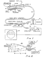
- Figure- 1 is a partial block and partial schematic diagram of one embodiment of the fiber optic pressure sensor according to the invention.
- Figure 2 is a schematic representation of another embodiment of the fiber optic pressure sensor.
- Referring now to Figure 1 there is shown in somewhat schematic form a single fiber embodiment of the fiber optic pressure sensor apparatus commencing with a
catheter sensing tip 10. Thesensing tip 10 comprises a molded optical plastic lens 11 having a sphericallycurved surface 12 at the face opposite that into which theoptic fiber 13 is fastened. The tip also comprises a thinpolyester reflecting diaphragm 14 which is spaced and fastened a smal-1 distance away from the lens by acylinder member 15. The diaphragm is pressure responsive. An air vent 16 in the form of a small hole through the lens allows the pressure to equalize with the atmosphere on the fiber side. The lens 11 is specifically designed to collimate or nearly collimate the cone of light emanating from thefiber 13 and to direct the light to the reflectingdiaphragm 14. Although the lens is described above as a conventional molded optical plastic lens, no such limitation is intended and the lens may be of other types such as a graded index lens, often called GRIN or Selfoc, for example. The pressure deformable mirror diaphragm cooperates with the lens as a lens-mirror-lens optical system, with the diaphragm modulating the effective focal length of the lens-mirror combination. The diaphragm is shown in a deformed position resulting from pressure against the outside, with no pressure the diaphragm will be more flat. - The sensing tip is affixed at the end of a
catheter 20. The sensor tip is of the same diameter as the catheter and theoptical fiber 13 is small in diameter and fits inside the hollow catheter. Thecatheter 20 near the connector has an aperture for communicating atmospheric pressure to the inside ofdiaphragm 14. Thesensing tip portion 10 of the pressure catheter is shown much enlarged in Figure 1 for purposes of clarity in explanation. Alight source 21 andsuitable lens 22 focuses the light into theother end 23 of the fiber optic. Thelight source 21 may also be a solid state light source which abuts directly against the end of the fiber. A conventionaldirectional coupler 24 transmits the light from the source to thefiber 13 and channels the reflected light to adetector 25. The electrical signal processing electronics such as anamplifier 26 anddisplay 27 receive the signals from thedetector 25 for converting the optical signal to an electrical signal which can be further conditioned. displayed or recorded. - In the undistorted position of the mirror diaphragm the fiber end is imaged onto itself with unit magnification. When the mirror diaphragm is distorted by pressure, the radiation is spread to cover a larger area, that is, the focal length of the lens-mirror combination is changed. Thus the amount of reflected light collected by the fiber varies as a function of the pressure.
- Figure 2 discloses diagrammatically another embodiment of the sensing head 10' in which a dual optic fiber, that is, an
input fiber 13 and an output fiber ist is fastened to the lens 11'. Light emanating from theinput fiber 13 is collimated by the lens 11'towards the reflecting diaphragm 14'. The reflected light is refocused by the lens 11' toward the output fiber 13'. Pressure applied to the diaphragm 14' produces a spherical curvature of radius R which causes the image to be magnified and focussed beyond the end of the output fiber 13'. The Figure 2 modification of the sensing head is currently the preferred embodiment because it is more amenable to reproducibility. - While the reflecting diaphragm has been indicated above as being formed of polyester film, other diaphragm materials have been tested including stainless steel, aluminum and brass.
Claims (5)
1. Fiber optic pressure sensor apparatus, in particular intravascular blood pressure catheter, comprising a light source, fiber optic means, a pressure responsive reflecting diaphragm and means for detecting the reflected lignt, characterized by light-collimating lens means (11, 11') at the end of the fiber optic means (13, 13') and positioned for directing a column of light to the pressure-deformable reflecting diaphragm (14, 14'), with said diaphragm when being un- . deformed reflecting maximum light back to said lens means and when being distorted by increasing pressure reflecting less of the light in a direction to fall on said lens means.
2. Sensor according to claim 1, characterized in that said fiber optic means comprises a transmit (13) and a return (13') optic fiber.
3. Sensor according to claim 1 or 2, character- ized in that the fiber optic means (13, 13') extends into a sensor tip (10, 10') including the pressure deformable diaphragm (14, 14') and the light-collimating lens means (11, 11').
4. Sensor according to claim 3, characterized in that said sensor tip (10, 10') is hollow and comprises a sealed air chamber between said diaphragm (14, 14') and said lens means (11, 11').
5. Sensor according to claim 4, characterized by an air passage (16) through said lens means (11) so that ambient atmospheric pressure can be communicated to said chamber.
Applications Claiming Priority (2)
| Application Number | Priority Date | Filing Date | Title |
|---|---|---|---|
| US29897281A | 1981-09-03 | 1981-09-03 | |
| US298972 | 1981-09-03 |
Publications (2)
| Publication Number | Publication Date |
|---|---|
| EP0074055A2 true EP0074055A2 (en) | 1983-03-16 |
| EP0074055A3 EP0074055A3 (en) | 1984-09-12 |
Family
ID=23152792
Family Applications (1)
| Application Number | Title | Priority Date | Filing Date |
|---|---|---|---|
| EP82107979A Withdrawn EP0074055A3 (en) | 1981-09-03 | 1982-08-31 | Fiber optic pressure sensor |
Country Status (2)
| Country | Link |
|---|---|
| EP (1) | EP0074055A3 (en) |
| JP (1) | JPS5847232A (en) |
Cited By (8)
| Publication number | Priority date | Publication date | Assignee | Title |
|---|---|---|---|---|
| EP0183329A2 (en) * | 1984-11-28 | 1986-06-04 | The Regents Of The University Of California | Pressure-sensitive optrode |
| EP0184721A2 (en) * | 1984-12-13 | 1986-06-18 | Kabushiki Kaisha Toshiba | Pressure measuring system |
| DE3614659A1 (en) * | 1985-04-30 | 1986-10-30 | Metatech Corp., Northbrook, Ill. | GLASS FIBER OPTIC TRANSMITTER |
| EP0286374A2 (en) * | 1987-04-07 | 1988-10-12 | Qwikcall! Corporation | Apparatus and method for sensing and preventing incontinent episodes |
| FR2638523A1 (en) * | 1988-11-03 | 1990-05-04 | Serbe | Pressure microsensor, in particular for medical studies |
| GB2234344A (en) * | 1989-06-05 | 1991-01-30 | Medical & Diagnostic Systems L | Fibre optic pressure or temperature transducers |
| US5045282A (en) * | 1987-10-16 | 1991-09-03 | Optical Chemical Tech. Ltd. | Optical fiber sensing device for analysis |
| GB2374925A (en) * | 2001-04-24 | 2002-10-30 | Anant Sharma | Pressure detectors |
Citations (7)
| Publication number | Priority date | Publication date | Assignee | Title |
|---|---|---|---|---|
| US3249105A (en) * | 1963-04-19 | 1966-05-03 | American Optical Corp | Devices for measuring blood pressure |
| US3273447A (en) * | 1963-08-26 | 1966-09-20 | Franklin Institute | Detection and measurement device having a small flexible fiber transmission line |
| US4201222A (en) * | 1977-08-31 | 1980-05-06 | Thomas Haase | Method and apparatus for in vivo measurement of blood gas partial pressures, blood pressure and blood pulse |
| FR2444258A1 (en) * | 1978-12-13 | 1980-07-11 | United Technologies Corp | ELECTRO-OPTICAL OSCILLATOR AND METHOD FOR OPERATING IT |
| EP0025566A2 (en) * | 1979-09-17 | 1981-03-25 | Siemens Aktiengesellschaft | Optical device for measuring small pressure differences by means of light intensity changes |
| JPS5760239A (en) * | 1980-09-29 | 1982-04-12 | Mitsubishi Electric Corp | Pressure sensor |
| GB2086572A (en) * | 1980-10-27 | 1982-05-12 | Rosemount Eng Co Ltd | Differential pressure measuring apparatus |
-
1982
- 1982-08-31 EP EP82107979A patent/EP0074055A3/en not_active Withdrawn
- 1982-09-01 JP JP15081482A patent/JPS5847232A/en active Pending
Patent Citations (7)
| Publication number | Priority date | Publication date | Assignee | Title |
|---|---|---|---|---|
| US3249105A (en) * | 1963-04-19 | 1966-05-03 | American Optical Corp | Devices for measuring blood pressure |
| US3273447A (en) * | 1963-08-26 | 1966-09-20 | Franklin Institute | Detection and measurement device having a small flexible fiber transmission line |
| US4201222A (en) * | 1977-08-31 | 1980-05-06 | Thomas Haase | Method and apparatus for in vivo measurement of blood gas partial pressures, blood pressure and blood pulse |
| FR2444258A1 (en) * | 1978-12-13 | 1980-07-11 | United Technologies Corp | ELECTRO-OPTICAL OSCILLATOR AND METHOD FOR OPERATING IT |
| EP0025566A2 (en) * | 1979-09-17 | 1981-03-25 | Siemens Aktiengesellschaft | Optical device for measuring small pressure differences by means of light intensity changes |
| JPS5760239A (en) * | 1980-09-29 | 1982-04-12 | Mitsubishi Electric Corp | Pressure sensor |
| GB2086572A (en) * | 1980-10-27 | 1982-05-12 | Rosemount Eng Co Ltd | Differential pressure measuring apparatus |
Non-Patent Citations (1)
| Title |
|---|
| PATENTS ABSTRACTS OF JAPAN, vol. 6, no. 137 (P-130)[1015], 24th July 1982 & JP - A - 57 60 239 (MITSUBISHI DENKI K.K.) 12-04-1982 * |
Cited By (13)
| Publication number | Priority date | Publication date | Assignee | Title |
|---|---|---|---|---|
| EP0183329A3 (en) * | 1984-11-28 | 1989-07-26 | The Regents Of The University Of California | Pressure-sensitive optrode |
| EP0183329A2 (en) * | 1984-11-28 | 1986-06-04 | The Regents Of The University Of California | Pressure-sensitive optrode |
| EP0184721A3 (en) * | 1984-12-13 | 1989-04-19 | Kabushiki Kaisha Toshiba | Pressure measuring system |
| EP0184721A2 (en) * | 1984-12-13 | 1986-06-18 | Kabushiki Kaisha Toshiba | Pressure measuring system |
| GB2174805B (en) * | 1985-04-30 | 1989-07-05 | Metatech Corp | Fiber optic transducers |
| GB2174805A (en) * | 1985-04-30 | 1986-11-12 | Metatech Corp | Fiber optic transducers |
| DE3614659A1 (en) * | 1985-04-30 | 1986-10-30 | Metatech Corp., Northbrook, Ill. | GLASS FIBER OPTIC TRANSMITTER |
| EP0286374A2 (en) * | 1987-04-07 | 1988-10-12 | Qwikcall! Corporation | Apparatus and method for sensing and preventing incontinent episodes |
| EP0286374A3 (en) * | 1987-04-07 | 1990-05-16 | Qwikcall! Corporation | Apparatus and method for sensing and preventing incontinent episodes |
| US5045282A (en) * | 1987-10-16 | 1991-09-03 | Optical Chemical Tech. Ltd. | Optical fiber sensing device for analysis |
| FR2638523A1 (en) * | 1988-11-03 | 1990-05-04 | Serbe | Pressure microsensor, in particular for medical studies |
| GB2234344A (en) * | 1989-06-05 | 1991-01-30 | Medical & Diagnostic Systems L | Fibre optic pressure or temperature transducers |
| GB2374925A (en) * | 2001-04-24 | 2002-10-30 | Anant Sharma | Pressure detectors |
Also Published As
| Publication number | Publication date |
|---|---|
| EP0074055A3 (en) | 1984-09-12 |
| JPS5847232A (en) | 1983-03-18 |
Similar Documents
| Publication | Publication Date | Title |
|---|---|---|
| US4487206A (en) | Fiber optic pressure sensor with temperature compensation and reference | |
| US3215135A (en) | Miniature pressure gauge for the measurement of intravascular blood pressure | |
| US4653905A (en) | Fiber optic range finder systems | |
| US6320184B1 (en) | Optoelectric measuring device for monitoring combustion processes | |
| JP3040130B2 (en) | Optical fiber sensor and system for measuring three parameters | |
| US5422478A (en) | Fiberoptic pressure sensor having drift correction means for insitu calibration | |
| US4734577A (en) | Continuous strain measurement along a span | |
| US4158310A (en) | Optical pressure transducer of randomly distributed fiber optics | |
| US3686958A (en) | Fiber optic pressure detector | |
| EP0815434B1 (en) | Diffuse reflectance probe | |
| US3249105A (en) | Devices for measuring blood pressure | |
| CA2088167A1 (en) | Fibre-optical pressure sensor | |
| EP0348224A1 (en) | Pressure-pulse-wave detecting apparatus | |
| GB2037448A (en) | Optical temperature sensor | |
| JPS6399839A (en) | Optical fiber pressure converter using single optical fiber and its production | |
| JPH037370B2 (en) | ||
| EP0074055A2 (en) | Fiber optic pressure sensor | |
| EP0403630A1 (en) | Infrared thermometer with fiber optic remote pickup and method | |
| JPS6354146A (en) | Pressure monitor apparatus | |
| US6462808B2 (en) | Small optical microphone/sensor | |
| US4666304A (en) | Optical measurement apparatus | |
| GB2160310A (en) | Optical displacement sensor | |
| JPH0311644B2 (en) | ||
| US3338090A (en) | Applanation tonometer | |
| KR910001840B1 (en) | Displacement detection |
Legal Events
| Date | Code | Title | Description |
|---|---|---|---|
| PUAI | Public reference made under article 153(3) epc to a published international application that has entered the european phase |
Free format text: ORIGINAL CODE: 0009012 |
|
| AK | Designated contracting states |
Designated state(s): DE FR GB IT NL |
|
| PUAL | Search report despatched |
Free format text: ORIGINAL CODE: 0009013 |
|
| AK | Designated contracting states |
Designated state(s): DE FR GB IT NL |
|
| STAA | Information on the status of an ep patent application or granted ep patent |
Free format text: STATUS: THE APPLICATION IS DEEMED TO BE WITHDRAWN |
|
| 18D | Application deemed to be withdrawn |
Effective date: 19850303 |
|
| RIN1 | Information on inventor provided before grant (corrected) |
Inventor name: AAGARD, ROGER L. |