EP0073614A2 - Double-tuned single coil probe for nuclear magnetic resonance spectrometer - Google Patents
Double-tuned single coil probe for nuclear magnetic resonance spectrometer Download PDFInfo
- Publication number
- EP0073614A2 EP0073614A2 EP82304397A EP82304397A EP0073614A2 EP 0073614 A2 EP0073614 A2 EP 0073614A2 EP 82304397 A EP82304397 A EP 82304397A EP 82304397 A EP82304397 A EP 82304397A EP 0073614 A2 EP0073614 A2 EP 0073614A2
- Authority
- EP
- European Patent Office
- Prior art keywords
- probe
- transmission line
- sample
- low frequency
- high frequency
- Prior art date
- Legal status (The legal status is an assumption and is not a legal conclusion. Google has not performed a legal analysis and makes no representation as to the accuracy of the status listed.)
- Granted
Links
Images

Classifications
-
- G—PHYSICS
- G01—MEASURING; TESTING
- G01R—MEASURING ELECTRIC VARIABLES; MEASURING MAGNETIC VARIABLES
- G01R33/00—Arrangements or instruments for measuring magnetic variables
- G01R33/20—Arrangements or instruments for measuring magnetic variables involving magnetic resonance
- G01R33/28—Details of apparatus provided for in groups G01R33/44 - G01R33/64
- G01R33/32—Excitation or detection systems, e.g. using radio frequency signals
- G01R33/36—Electrical details, e.g. matching or coupling of the coil to the receiver
- G01R33/3628—Tuning/matching of the transmit/receive coil
- G01R33/3635—Multi-frequency operation
-
- G—PHYSICS
- G01—MEASURING; TESTING
- G01R—MEASURING ELECTRIC VARIABLES; MEASURING MAGNETIC VARIABLES
- G01R33/00—Arrangements or instruments for measuring magnetic variables
- G01R33/20—Arrangements or instruments for measuring magnetic variables involving magnetic resonance
- G01R33/62—Arrangements or instruments for measuring magnetic variables involving magnetic resonance using double resonance
Definitions
- This invention relates to nuclear magnetic resonance (NMR) spectrometers and more particularly to NMR spectrometers suitable for double-resonance experiments.
- NMR nuclear magnetic resonance
- a sample is irradiated with radio frequency fields of two different frequencies at.relatively high power levels, for example, 300-500 watts. It is important that good coupling to the sample be achieved at both frequencies.
- the efficiency of prior art probes is limited because of the size and magnetic restrictions for probe components.
- the present invention involves a double-tuned circuit which may be remotely disposed from the magnetic field which greatly reduces probe design problems because the size and magnetic restrictions for probe components are eliminated which results in enhanced sensitivity and a more efficient system.
- an improved double-tuned single coil probe for a nuclear magnetic resonance (NMR) spectrometer in which all the tuning elements can be situated remote from the sample coil outside of the magnetic field. This permits high power levels without break down of components which is especially advantageous for solids experiments.
- the improved probe has excellent efficiency for both irradiation of the sample and detection of the induced nuclear resonance signals.
- the probe comprises a sample coil connected to a double-tuned circuit means comprising a high frequency irradiation means and a low frequency irradiation means.
- the two frequencies have a ratio of about at least three to one or more and are in the radio frequency (RF) range.
- the high frequency irradiation means is connected to the sample coil through a transmission line means comprising a transmission line of a length of about one half of the high frequency wavelength-
- a preferred transmission line is a coaxial cable transmission line, more preferably a low-loss coaxial cable transmission line.
- the low frequency irradiation means is connected to the sample coil through the aforesaid transmission line means through an inductor means connected to the transmission line at the point along the transmission line where the magnitude of the impedance for the high frequency irradiation is at or about minimum.
- the probe is capable of sufficiently radiating a sample with both high and low frequency to excite the NMR of the sample nuclei at both frequencies and transmitting the signals generated by the sample NMR to a high frequency detection means and a low frequency detection means.
- An important feature of the invention is an inductor means disposed between the high frequency means comprising a conventional coupling circuit, and the low frequency means comprising a conventional coupling circuit.
- An example of a suitable coupling circuit is a circuit containing fixed and variable capacitors by which tuning can be achieved.
- the inductor means for example, an inductor coil, provides an inductive impedance to match the impedance of the low frequency means to the impedance of the transmission line means.
- the low frequency irradiation means comprises an RF generator connected to the inductor means through a capacitive tuning and matching circuit.
- the high frequency irradiation means comprises an RF generator connected to the transmission line through a capacitive tuning and matching circuit which circuit also contains a low frequency trap.
- Spectrometer 1 includes a sample coil 2 for exciting and detecting the NMR of the sample under analysis. Signals are transmitted to and from sample coil 2 through transmission line segments 3 and 4. Input excitation low' frequency (If) RF irradiation is fed to transmission line segment 3 through a circuit comprising tuner 11 and filter 12. The remainder of the lf input RF circuit comprises switch 13 connected to watt meter 14 connected to RF amplifier 15 which amplifier 15 connects through attenuator 16 to low frequency RF generator 17. The portion of the circuit from sample coil 2 through switch 13 also serves as part of the output low frequency RF detection system. From switch 13 the low frequency RF NMR output passes-through amplifier 18 to RF quadrature detectors 30.
- Input excitation low' frequency (If) RF irradiation is fed to transmission line segment 3 through a circuit comprising tuner 11 and filter 12.
- the remainder of the lf input RF circuit comprises switch 13 connected to watt meter 14 connected to RF amplifier 15 which amplifier 15 connects through attenuator 16
- Input excitation high frequency (hf) RF irradiation is fed to transmission line segment 4 through a circuit comprising tuner 21 and filter 22.
- Tuners 11 and 21, transmission line segments 3 and 4, and sample coil 2 comprise the probe circuit.
- the remainder of the hf input RF circuit comprises switch 23 connected to watt meter 24 connected to RF amplifier 25 which amplifier 25 connects through attenuator 26 to high frequency RF generator 27.
- the portion of the circuit from sample coil 2 through switch 23 also serves as part of the output high frequency RF detection system.
- From switch 23 the high frequency RF NMR output passes through amplifier 28 to RF quadrature detectors 30.
- a circuit also connects tuner 21 through RF pulse monitor 29 to control panel and oscilloscope system 31. Associated with control panel and oscilloscope system 31 is Magic Angle Spinner counter and monitor 32.
- Computer 34 capable of Fourier Transform analysis is connected to RF generators 17 and 27 and RF quadrature detectors 30.
- Sample coil 50 receives and transmits RF signals through a transmission line having a length d 2 of about X/2, where 1 is the wavelength of the high frequency irradiation.
- the transmission line comprises segment 51 of length dl and segment 52 of length d.
- Length d 1 is critical and determines the location of Junction Point B where the low frequency input and detection circuit connects with the aforesaid transmission line.
- Junction Point B must be located along the transmission line where the high frequency impedance is or about minimum. A method for calculating the location of Junction Point B and the corresponding length d l are described below.
- a low frequency circuit suitable for Carbon-13 irradiation comprises 22.6 Megahertz input port 56 adapted for a characteristic impedance, for example, 50 ohms, and a conventional coupling circuit comprising grounded capacitor 55 and variable capacitor 54 which coupling circuit is connected at point B through high Q inductor coil 53.
- a Q value as high as possible is desirable, but a Q value of at least 200 is satisfactory.
- Inductor coil 53' has sufficient inductance so that the impedance at point A looking toward Junction point B is inductive.
- the low frequency RF generator connects inductor coil 53 through a capacitive tuning and matching circuit.
- inductor coil 53 is illustrated in series, a suitable alternative comprises connecting an inductor coil in parallel at point B and impedance matching by tapping the inductor at the appropriate point.
- a high frequency circuit suitable for proton irradiation comprises a 90 Megahertz input port 61 adapted for a characteristic impedance, for example, 50 ohms, and a conventional coupling circuit comprising grounded capacitor 58 and variable capacitor 57.
- a trapping circuit for isolating low frequency irradiation comprising variable capacitor 59 in parallel with inductor coil 60 is connected between the high frequency generator and the coupling circuit.
- junction Point B where the minimum impedance occurs can be calculated from the transmission line equation 1.
- Z s is the input impedance for a transmission line of length d l
- Z r the receiving end impedance, in this case the sample coil 50
- Z o the characteristic impedance of the transmission line segment 51
- y ⁇ +j ⁇
- Junction Point B may be located experimentally by use of an RF impedance meter or volt meter.
- the probe of the invention gives a high operating Q resulting in a good signal-to-noise ratio, provides uniformity of irradiation at both frequencies since only a single coil is used, reduces design problems in the magnet gap since many of the circuit components may be located outside the magnetic field, and eliminates break down problems which occur in crossed coil systems.
Abstract
Description
- This invention relates to nuclear magnetic resonance (NMR) spectrometers and more particularly to NMR spectrometers suitable for double-resonance experiments.
- For some NMR analyses, a sample is irradiated with radio frequency fields of two different frequencies at.relatively high power levels, for example, 300-500 watts. It is important that good coupling to the sample be achieved at both frequencies. The efficiency of prior art probes is limited because of the size and magnetic restrictions for probe components. The present invention involves a double-tuned circuit which may be remotely disposed from the magnetic field which greatly reduces probe design problems because the size and magnetic restrictions for probe components are eliminated which results in enhanced sensitivity and a more efficient system.
- In accordance with this invention, an improved double-tuned single coil probe for a nuclear magnetic resonance (NMR) spectrometer is provided in which all the tuning elements can be situated remote from the sample coil outside of the magnetic field. This permits high power levels without break down of components which is especially advantageous for solids experiments. The improved probe has excellent efficiency for both irradiation of the sample and detection of the induced nuclear resonance signals. The probe comprises a sample coil connected to a double-tuned circuit means comprising a high frequency irradiation means and a low frequency irradiation means. The two frequencies have a ratio of about at least three to one or more and are in the radio frequency (RF) range. The high frequency irradiation means is connected to the sample coil through a transmission line means comprising a transmission line of a length of about one half of the high frequency wavelength- A preferred transmission line is a coaxial cable transmission line, more preferably a low-loss coaxial cable transmission line. The low frequency irradiation means is connected to the sample coil through the aforesaid transmission line means through an inductor means connected to the transmission line at the point along the transmission line where the magnitude of the impedance for the high frequency irradiation is at or about minimum.
- It is understood that the probe is capable of sufficiently radiating a sample with both high and low frequency to excite the NMR of the sample nuclei at both frequencies and transmitting the signals generated by the sample NMR to a high frequency detection means and a low frequency detection means.
- An important feature of the invention is an inductor means disposed between the high frequency means comprising a conventional coupling circuit, and the low frequency means comprising a conventional coupling circuit. An example of a suitable coupling circuit is a circuit containing fixed and variable capacitors by which tuning can be achieved. The inductor means, for example, an inductor coil, provides an inductive impedance to match the impedance of the low frequency means to the impedance of the transmission line means. Thus, the low frequency irradiation means comprises an RF generator connected to the inductor means through a capacitive tuning and matching circuit. The high frequency irradiation means comprises an RF generator connected to the transmission line through a capacitive tuning and matching circuit which circuit also contains a low frequency trap.
- These and other features of the invention will become more apparent by referring to the drawings and descriptions thereof.
-
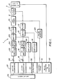
- Fig. 1 is a schematic view in block diagram form of the major components of an NMR spectrometer containing the improved probe of the present invention.
- Fig. 2 is a detailed circuit diagram illustrating an embodiment of the improved probe of the invention.
- Referring to Fig. 1, there is shown a double-tuned NMR spectrometer 1 of the invention. Spectrometer 1 includes a sample coil 2 for exciting and detecting the NMR of the sample under analysis. Signals are transmitted to and from sample coil 2 through
transmission line segments transmission line segment 3 through a circuit comprising tuner 11 andfilter 12. The remainder of the lf input RF circuit comprisesswitch 13 connected towatt meter 14 connected toRF amplifier 15 whichamplifier 15 connects throughattenuator 16 to lowfrequency RF generator 17. The portion of the circuit from sample coil 2 throughswitch 13 also serves as part of the output low frequency RF detection system. Fromswitch 13 the low frequency RF NMR output passes-throughamplifier 18 toRF quadrature detectors 30. - Input excitation high frequency (hf) RF irradiation is fed to
transmission line segment 4 through acircuit comprising tuner 21 andfilter 22.Tuners 11 and 21,transmission line segments switch 23 connected towatt meter 24 connected toRF amplifier 25 whichamplifier 25 connects throughattenuator 26 to highfrequency RF generator 27. The portion of the circuit from sample coil 2 throughswitch 23 also serves as part of the output high frequency RF detection system. Fromswitch 23 the high frequency RF NMR output passes throughamplifier 28 toRF quadrature detectors 30. A circuit also connectstuner 21 throughRF pulse monitor 29 to control panel andoscilloscope system 31. Associated with control panel andoscilloscope system 31 is Magic Angle Spinner counter andmonitor 32.Computer 34 capable of Fourier Transform analysis is connected toRF generators RF quadrature detectors 30. - A double-tuned single coil probe illustrative of an embodiment of the invention is shown in Fig. 2.
Sample coil 50 receives and transmits RF signals through a transmission line having a length d2 of about X/2, where 1 is the wavelength of the high frequency irradiation. The transmission line comprisessegment 51 of length dl andsegment 52 of length d. Length d1 is critical and determines the location of Junction Point B where the low frequency input and detection circuit connects with the aforesaid transmission line. Junction Point B must be located along the transmission line where the high frequency impedance is or about minimum. A method for calculating the location of Junction Point B and the corresponding length dl are described below. A low frequency circuit suitable for Carbon-13 irradiation comprises 22.6Megahertz input port 56 adapted for a characteristic impedance, for example, 50 ohms, and a conventional coupling circuit comprising groundedcapacitor 55 andvariable capacitor 54 which coupling circuit is connected at point B through highQ inductor coil 53. A Q value as high as possible is desirable, but a Q value of at least 200 is satisfactory. Inductor coil 53'has sufficient inductance so that the impedance at point A looking toward Junction point B is inductive. Thus, the low frequency RF generator connectsinductor coil 53 through a capacitive tuning and matching circuit. Althoughinductor coil 53 is illustrated in series, a suitable alternative comprises connecting an inductor coil in parallel at point B and impedance matching by tapping the inductor at the appropriate point. - A high frequency circuit suitable for proton irradiation comprises a 90
Megahertz input port 61 adapted for a characteristic impedance, for example, 50 ohms, and a conventional coupling circuit comprisinggrounded capacitor 58 andvariable capacitor 57. A trapping circuit for isolating low frequency irradiation comprisingvariable capacitor 59 in parallel withinductor coil 60 is connected between the high frequency generator and the coupling circuit. - Junction Point B where the minimum impedance occurs can be calculated from the transmission line equation 1.

sample coil 50, Zo the characteristic impedance of thetransmission line segment 51, and y =α+jβ where a is the attenuation constant in Nepers/unit length of the transmission line and β=2π/λ, where λ is the wavelength of the high frequency irradiation in the transmission line. - As an example, for an NMR spectrometer operating at a high frequency of 90 MHz, a transmission line with
Z o=50 ohms (RG-225/U) and a sample coil with an inductance of 0.64 µh and a Q of 200, Junction Point a can be calculated. If the sample coil inductor is assumed to be purely reactive and the transmission line lossless (a=0) then Eq. 1 can be simplified and d1/λ is equal to .272 or dl =272λ. - The error involved by assuming that Zs is purely inductive and the transmission line lossless, is that a zero null is implied, whereas, actually a finite but low value exists. However, at Junction Point B there is a minimum voltage and low impedance which means it is the least sensitive spot to connect the low frequency circuit provided the added circuit's impedance is 10 or more times the impedance at point B. Impedance measurements indicated that the impedance at point B is less than about 5 ohms.
- Alernatively, Junction Point B may be located experimentally by use of an RF impedance meter or volt meter.
- The probe of the invention gives a high operating Q resulting in a good signal-to-noise ratio, provides uniformity of irradiation at both frequencies since only a single coil is used, reduces design problems in the magnet gap since many of the circuit components may be located outside the magnetic field, and eliminates break down problems which occur in crossed coil systems.
- Although the invention has been illustrated by typical examples, it is not limited thereto. Changes and modifications of the examples of the invention herein chosen for purposes of disclosure can be made which do not constitute departure from the spirit and scope of the invention.
Claims (8)
Applications Claiming Priority (2)
| Application Number | Priority Date | Filing Date | Title |
|---|---|---|---|
| US295940 | 1981-08-24 | ||
| US06/295,940 US4446431A (en) | 1981-08-24 | 1981-08-24 | Double-tuned single coil probe for nuclear magnetic resonance spectrometer |
Publications (3)
| Publication Number | Publication Date |
|---|---|
| EP0073614A2 true EP0073614A2 (en) | 1983-03-09 |
| EP0073614A3 EP0073614A3 (en) | 1983-04-06 |
| EP0073614B1 EP0073614B1 (en) | 1986-02-05 |
Family
ID=23139883
Family Applications (1)
| Application Number | Title | Priority Date | Filing Date |
|---|---|---|---|
| EP82304397A Expired EP0073614B1 (en) | 1981-08-24 | 1982-08-20 | Double-tuned single coil probe for nuclear magnetic resonance spectrometer |
Country Status (5)
| Country | Link |
|---|---|
| US (1) | US4446431A (en) |
| EP (1) | EP0073614B1 (en) |
| JP (1) | JPS5835451A (en) |
| CA (1) | CA1193657A (en) |
| DE (1) | DE3268959D1 (en) |
Cited By (9)
| Publication number | Priority date | Publication date | Assignee | Title |
|---|---|---|---|---|
| EP0155978A1 (en) * | 1984-03-29 | 1985-10-02 | Oxford Research Systems Limited | Method of operating a nuclear magnetic resonance spectrometer |
| EP0166953A1 (en) * | 1984-06-07 | 1986-01-08 | Siemens Aktiengesellschaft | Apparatus for nuclear spin tomography |
| EP0171972A2 (en) * | 1984-08-16 | 1986-02-19 | Picker International, Inc. | Nuclear magnetic resonance radio frequency antenna |
| EP0173363A1 (en) * | 1984-07-30 | 1986-03-05 | Koninklijke Philips Electronics N.V. | MR-apparatus having a transmission-measuring coil for high frequencies |
| EP0196134A1 (en) * | 1985-03-22 | 1986-10-01 | Koninklijke Philips Electronics N.V. | Magnetic resonance imaging apparatus including two orthogonal r.f. coils |
| FR2590993A1 (en) * | 1985-11-29 | 1987-06-05 | Thomson Cgr | DEVICE AND METHOD FOR ADJUSTING A RADIO FREQUENCY ANTENNA OF A NUCLEAR MAGNETIC RESONANCE APPARATUS |
| EP0256370A1 (en) * | 1986-08-12 | 1988-02-24 | Siemens Aktiengesellschaft | Antenna arrangement for exciting and recording nuclear magnetic resonance |
| EP0336591A2 (en) * | 1988-04-08 | 1989-10-11 | Varian Associates, Inc. | Double tuned circuit for distrubuted lumped capacitance observe coils |
| EP1607760A1 (en) * | 2004-06-18 | 2005-12-21 | Bruker Biospin SA | Circuit for supplying power to a coil and NMR spectrometer comprising such a circuit |
Families Citing this family (20)
| Publication number | Priority date | Publication date | Assignee | Title |
|---|---|---|---|---|
| US4656281A (en) * | 1983-03-18 | 1987-04-07 | Usv Pharmaceutical Corp. | Imidazo quinoline compounds useful as anti-allergy agents |
| US4641098A (en) * | 1985-03-15 | 1987-02-03 | Doty Scientific, Inc. | Parallel single turn saddle resonator for nuclear magnetic resonance signal reception |
| US4691163A (en) * | 1985-03-19 | 1987-09-01 | Elscint Ltd. | Dual frequency surface probes |
| JPS62227342A (en) * | 1986-03-31 | 1987-10-06 | 株式会社東芝 | Quadrature detector |
| US4742304A (en) * | 1986-05-02 | 1988-05-03 | Phospho-Energetics, Inc. | Multiple tuning NMR probe |
| US5170789A (en) * | 1987-06-17 | 1992-12-15 | Perinchery Narayan | Insertable NMR coil probe |
| US4792759A (en) * | 1987-07-29 | 1988-12-20 | Elscint Ltd. | Multi-frequency surface probe |
| DE4002160A1 (en) * | 1990-01-25 | 1991-08-08 | Bruker Analytische Messtechnik | Double tuned single coil sampling head for NMR measurements - allows transmission line to be shortened if capacitors are includes in lower end of inner conductor |
| US5038105A (en) * | 1990-02-09 | 1991-08-06 | Spectroscopy Imaging Systems Corporation | Series/parallel double-tuned NMR coils |
| US5162739A (en) * | 1991-04-05 | 1992-11-10 | F. David Doty | Balanced multi-tuned high-power broadband coil for nmr |
| US5675254A (en) * | 1993-06-02 | 1997-10-07 | The Board Of Trustees Of The University Of Illinois | Double-resonance MRI coil |
| US5424645A (en) * | 1993-11-18 | 1995-06-13 | Doty Scientific, Inc. | Doubly broadband triple resonance or quad resonance NMR probe circuit |
| AU5369398A (en) | 1996-12-02 | 1998-06-29 | Trustees Of Columbia University In The City Of New York, The | Multiple resonance superconducting probe |
| CA2279505A1 (en) * | 1997-02-03 | 1998-08-06 | The Trustees Of Columbia University In The City Of New York | Formation of superconducting devices using a selective etching technique |
| US5861748A (en) * | 1997-07-10 | 1999-01-19 | Schaefer; Jacob | Multi-tuned single coil transmission line probe for nuclear magnetic resonance spectrometer |
| DE10004423C2 (en) * | 2000-02-02 | 2002-01-31 | Siemens Ag | Additional device for a control device for a magnetic resonance tomograph |
| DE10019990C2 (en) * | 2000-04-22 | 2002-04-04 | Bruker Analytik Gmbh | Probe head for nuclear magnetic resonance measurements |
| FR2871891B1 (en) * | 2004-06-18 | 2006-09-01 | Bruker Biospin Sa Sa | MULTIFREQUENCIAL POWER SUPPLY CIRCUIT AND PROBE AND NMR SPECTROMETER COMPRISING SUCH A CIRCUIT |
| US7615997B2 (en) * | 2005-10-28 | 2009-11-10 | Koninklijke Philips Electronics N.V. | Simultaneous MR-excitation of multiple nuclei with a single RF amplifier |
| WO2008086031A1 (en) * | 2007-01-10 | 2008-07-17 | University Of Florida Research Foundation, Inc. | Method and apparatus for tuning and matching mri/nmr probe |
Citations (3)
| Publication number | Priority date | Publication date | Assignee | Title |
|---|---|---|---|---|
| US3434043A (en) * | 1966-02-14 | 1969-03-18 | Varian Associates | Nuclear magnetic resonance probe apparatus having double tuned coil systems for spectrometers employing an internal reference |
| US3777254A (en) * | 1968-01-15 | 1973-12-04 | J Kleiman | Nuclear magnetic resonance spectrometer with jointly functioning external and internal resonance stabilization systems |
| US4051429A (en) * | 1975-02-04 | 1977-09-27 | Nihon Denshi Kabushiki Kaisha | Nuclear magnetic resonance apparatus |
Family Cites Families (4)
| Publication number | Priority date | Publication date | Assignee | Title |
|---|---|---|---|---|
| US3795855A (en) * | 1971-12-08 | 1974-03-05 | Cyclotron Corp | Magnetic resonance probe system |
| US3858112A (en) * | 1973-09-20 | 1974-12-31 | Nippon Electric Varian Ltd | A receiver circuit including a crystal resonator for nuclear magnetic resonance signals of two different frequencies |
| US4129822A (en) * | 1975-04-24 | 1978-12-12 | Traficante D | Wide-band nuclear magnetic resonance spectrometer |
| US4095168A (en) * | 1977-02-22 | 1978-06-13 | Varian Associates, Inc. | Rf pick-up coil circuit for a wide tuning range nuclear magnetic resonance probe |
-
1981
- 1981-08-24 US US06/295,940 patent/US4446431A/en not_active Expired - Lifetime
-
1982
- 1982-07-19 JP JP57125612A patent/JPS5835451A/en active Pending
- 1982-08-20 EP EP82304397A patent/EP0073614B1/en not_active Expired
- 1982-08-20 DE DE8282304397T patent/DE3268959D1/en not_active Expired
- 1982-08-23 CA CA000409902A patent/CA1193657A/en not_active Expired
Patent Citations (3)
| Publication number | Priority date | Publication date | Assignee | Title |
|---|---|---|---|---|
| US3434043A (en) * | 1966-02-14 | 1969-03-18 | Varian Associates | Nuclear magnetic resonance probe apparatus having double tuned coil systems for spectrometers employing an internal reference |
| US3777254A (en) * | 1968-01-15 | 1973-12-04 | J Kleiman | Nuclear magnetic resonance spectrometer with jointly functioning external and internal resonance stabilization systems |
| US4051429A (en) * | 1975-02-04 | 1977-09-27 | Nihon Denshi Kabushiki Kaisha | Nuclear magnetic resonance apparatus |
Non-Patent Citations (1)
| Title |
|---|
| JOURNAL OF PHYSICS E, SCIENT. INSTR., Vol. 13, No. 3, March 1980 Bristol A.G. FERRIGE et al. "Improvement of FTNMR sensitivity on a spectrometer normally using a double-tuned receiver coil" pages 283, 284 * |
Cited By (15)
| Publication number | Priority date | Publication date | Assignee | Title |
|---|---|---|---|---|
| EP0155978A1 (en) * | 1984-03-29 | 1985-10-02 | Oxford Research Systems Limited | Method of operating a nuclear magnetic resonance spectrometer |
| EP0166953A1 (en) * | 1984-06-07 | 1986-01-08 | Siemens Aktiengesellschaft | Apparatus for nuclear spin tomography |
| EP0173363A1 (en) * | 1984-07-30 | 1986-03-05 | Koninklijke Philips Electronics N.V. | MR-apparatus having a transmission-measuring coil for high frequencies |
| EP0171972A2 (en) * | 1984-08-16 | 1986-02-19 | Picker International, Inc. | Nuclear magnetic resonance radio frequency antenna |
| EP0171972A3 (en) * | 1984-08-16 | 1987-04-15 | Picker International, Inc. | Nuclear magnetic resonance radio frequency antenna |
| EP0196134A1 (en) * | 1985-03-22 | 1986-10-01 | Koninklijke Philips Electronics N.V. | Magnetic resonance imaging apparatus including two orthogonal r.f. coils |
| FR2590993A1 (en) * | 1985-11-29 | 1987-06-05 | Thomson Cgr | DEVICE AND METHOD FOR ADJUSTING A RADIO FREQUENCY ANTENNA OF A NUCLEAR MAGNETIC RESONANCE APPARATUS |
| EP0230168A1 (en) * | 1985-11-29 | 1987-07-29 | General Electric Cgr S.A. | Device and method for adjusting a radio frequency antenna in a nuclear magnetic resonance apparatus |
| US4843323A (en) * | 1985-11-29 | 1989-06-27 | Thomson-Cgr | Device and method for adjusting a radiofrequency antenna of a nuclear magnetic resonance apparatus |
| EP0256370A1 (en) * | 1986-08-12 | 1988-02-24 | Siemens Aktiengesellschaft | Antenna arrangement for exciting and recording nuclear magnetic resonance |
| EP0336591A2 (en) * | 1988-04-08 | 1989-10-11 | Varian Associates, Inc. | Double tuned circuit for distrubuted lumped capacitance observe coils |
| EP0336591A3 (en) * | 1988-04-08 | 1991-01-02 | Varian Associates, Inc. | Double tuned circuit for distrubuted lumped capacitance observe coils |
| EP1607760A1 (en) * | 2004-06-18 | 2005-12-21 | Bruker Biospin SA | Circuit for supplying power to a coil and NMR spectrometer comprising such a circuit |
| FR2871892A1 (en) * | 2004-06-18 | 2005-12-23 | Bruker Biospin Sa Sa | POWER SUPPLY CIRCUIT OF A COIL AND PROBE AND NMR SPECTROMETER COMPRISING SUCH A CIRCUIT |
| US7196522B2 (en) | 2004-06-18 | 2007-03-27 | Bruker Biospin Sa (Societe Anonyme) | Power circuit of a coil and probe and NMR spectrometer comprising such a circuit |
Also Published As
| Publication number | Publication date |
|---|---|
| CA1193657A (en) | 1985-09-17 |
| DE3268959D1 (en) | 1986-03-20 |
| EP0073614B1 (en) | 1986-02-05 |
| JPS5835451A (en) | 1983-03-02 |
| EP0073614A3 (en) | 1983-04-06 |
| US4446431A (en) | 1984-05-01 |
Similar Documents
| Publication | Publication Date | Title |
|---|---|---|
| US4446431A (en) | Double-tuned single coil probe for nuclear magnetic resonance spectrometer | |
| US4916398A (en) | Efficient remote transmission line probe tuning for NMR apparatus | |
| US4691163A (en) | Dual frequency surface probes | |
| EP0522037B1 (en) | Double tuned nmr coils | |
| Froncisz et al. | Inductive (flux linkage) coupling to local coils in magnetic resonance imaging and spectroscopy | |
| US4833412A (en) | Double tuned circuit for distributed lumped capacitance observe coils | |
| Bendall et al. | Elimination of coupling between cylindrical transmit coils and surface‐receive coils for in vivo NMR | |
| US4792759A (en) | Multi-frequency surface probe | |
| EP0551441B1 (en) | Multi-resonant nmr coils | |
| US5038105A (en) | Series/parallel double-tuned NMR coils | |
| US6150817A (en) | Magnetic resonance apparatus having reduced "dead time" | |
| US5861748A (en) | Multi-tuned single coil transmission line probe for nuclear magnetic resonance spectrometer | |
| US3434043A (en) | Nuclear magnetic resonance probe apparatus having double tuned coil systems for spectrometers employing an internal reference | |
| JPH08252237A (en) | Magnetic resonance diagnostic system | |
| EP0312586B1 (en) | Spurious resonance control for nmr observe coils | |
| EP0937262B1 (en) | Method for reducing "dead time" in a magnetic resonance apparatus | |
| JPH0556828B2 (en) | ||
| JP2714044B2 (en) | Double tuning high frequency coil for magnetic resonance equipment. | |
| US3502963A (en) | Single coil nuclear resonance spectrometer having the radio frequency excitation directionally coupled into the coil | |
| US5055792A (en) | Miniaturized surface probes | |
| JP2965178B2 (en) | Transmitter / receiver circuit in nuclear magnetic resonance equipment | |
| GB2343000A (en) | NMR spectrometer with protection from reflected harmonics | |
| SU721735A1 (en) | Magnetic resonance signal sensor | |
| JPS6246242A (en) | Detection circuit of fourier transformation type nuclear magnetic resonance apparatus | |
| JPS60181670A (en) | Resonance signal detection circuit of nuclear magnetic resonance apparatus |
Legal Events
| Date | Code | Title | Description |
|---|---|---|---|
| PUAI | Public reference made under article 153(3) epc to a published international application that has entered the european phase |
Free format text: ORIGINAL CODE: 0009012 |
|
| PUAL | Search report despatched |
Free format text: ORIGINAL CODE: 0009013 |
|
| AK | Designated contracting states |
Designated state(s): BE CH DE GB LI |
|
| AK | Designated contracting states |
Designated state(s): BE CH DE GB LI |
|
| 17P | Request for examination filed |
Effective date: 19830509 |
|
| GRAA | (expected) grant |
Free format text: ORIGINAL CODE: 0009210 |
|
| AK | Designated contracting states |
Designated state(s): BE CH DE GB LI |
|
| REF | Corresponds to: |
Ref document number: 3268959 Country of ref document: DE Date of ref document: 19860320 |
|
| PLBE | No opposition filed within time limit |
Free format text: ORIGINAL CODE: 0009261 |
|
| STAA | Information on the status of an ep patent application or granted ep patent |
Free format text: STATUS: NO OPPOSITION FILED WITHIN TIME LIMIT |
|
| 26N | No opposition filed | ||
| PG25 | Lapsed in a contracting state [announced via postgrant information from national office to epo] |
Ref country code: GB Effective date: 19890820 |
|
| PG25 | Lapsed in a contracting state [announced via postgrant information from national office to epo] |
Ref country code: LI Effective date: 19890831 Ref country code: CH Effective date: 19890831 Ref country code: BE Effective date: 19890831 |
|
| BERE | Be: lapsed |
Owner name: MONSANTO CY Effective date: 19890831 |
|
| GBPC | Gb: european patent ceased through non-payment of renewal fee | ||
| REG | Reference to a national code |
Ref country code: CH Ref legal event code: PL |
|
| PG25 | Lapsed in a contracting state [announced via postgrant information from national office to epo] |
Ref country code: DE Effective date: 19900501 |