EP0073513B2 - Method of carrying out an analytical determination, and suitable means therefor - Google Patents
Method of carrying out an analytical determination, and suitable means therefor Download PDFInfo
- Publication number
- EP0073513B2 EP0073513B2 EP82107972A EP82107972A EP0073513B2 EP 0073513 B2 EP0073513 B2 EP 0073513B2 EP 82107972 A EP82107972 A EP 82107972A EP 82107972 A EP82107972 A EP 82107972A EP 0073513 B2 EP0073513 B2 EP 0073513B2
- Authority
- EP
- European Patent Office
- Prior art keywords
- force
- reagent
- solution
- transport
- sample
- Prior art date
- Legal status (The legal status is an assumption and is not a legal conclusion. Google has not performed a legal analysis and makes no representation as to the accuracy of the status listed.)
- Expired - Lifetime
Links
- 238000000034 method Methods 0.000 title claims abstract description 56
- 239000003153 chemical reaction reagent Substances 0.000 claims abstract description 79
- 230000032258 transport Effects 0.000 claims abstract description 24
- 238000002156 mixing Methods 0.000 claims abstract description 17
- 230000008569 process Effects 0.000 claims abstract description 16
- 239000012488 sample solution Substances 0.000 claims abstract description 14
- 238000005259 measurement Methods 0.000 claims abstract description 12
- 239000011541 reaction mixture Substances 0.000 claims abstract description 4
- 230000001105 regulatory effect Effects 0.000 claims abstract description 3
- 239000012530 fluid Substances 0.000 claims abstract 2
- 239000000523 sample Substances 0.000 claims description 32
- 239000002250 absorbent Substances 0.000 claims description 7
- 230000002745 absorbent Effects 0.000 claims description 7
- 239000012876 carrier material Substances 0.000 claims description 6
- 239000000463 material Substances 0.000 claims description 4
- 239000004094 surface-active agent Substances 0.000 claims description 3
- 239000000203 mixture Substances 0.000 claims description 2
- 230000004075 alteration Effects 0.000 claims 1
- 238000010276 construction Methods 0.000 claims 1
- 238000011534 incubation Methods 0.000 claims 1
- 238000009423 ventilation Methods 0.000 claims 1
- 239000000243 solution Substances 0.000 description 45
- 239000007788 liquid Substances 0.000 description 20
- 238000004458 analytical method Methods 0.000 description 15
- XLYOFNOQVPJJNP-UHFFFAOYSA-N water Substances O XLYOFNOQVPJJNP-UHFFFAOYSA-N 0.000 description 12
- 230000000694 effects Effects 0.000 description 9
- 239000000126 substance Substances 0.000 description 8
- 238000003825 pressing Methods 0.000 description 7
- 238000006243 chemical reaction Methods 0.000 description 6
- 210000002966 serum Anatomy 0.000 description 6
- 102000004420 Creatine Kinase Human genes 0.000 description 5
- 108010042126 Creatine kinase Proteins 0.000 description 5
- 102000004190 Enzymes Human genes 0.000 description 5
- 108090000790 Enzymes Proteins 0.000 description 5
- WQZGKKKJIJFFOK-GASJEMHNSA-N Glucose Natural products OC[C@H]1OC(O)[C@H](O)[C@@H](O)[C@@H]1O WQZGKKKJIJFFOK-GASJEMHNSA-N 0.000 description 5
- 238000002835 absorbance Methods 0.000 description 5
- 230000008033 biological extinction Effects 0.000 description 5
- 239000008103 glucose Substances 0.000 description 5
- 239000004033 plastic Substances 0.000 description 5
- 229920003023 plastic Polymers 0.000 description 5
- 102000002260 Alkaline Phosphatase Human genes 0.000 description 4
- 108020004774 Alkaline Phosphatase Proteins 0.000 description 4
- BPYKTIZUTYGOLE-IFADSCNNSA-N Bilirubin Chemical compound N1C(=O)C(C)=C(C=C)\C1=C\C1=C(C)C(CCC(O)=O)=C(CC2=C(C(C)=C(\C=C/3C(=C(C=C)C(=O)N\3)C)N2)CCC(O)=O)N1 BPYKTIZUTYGOLE-IFADSCNNSA-N 0.000 description 4
- 230000008859 change Effects 0.000 description 4
- 238000007789 sealing Methods 0.000 description 4
- 239000003599 detergent Substances 0.000 description 3
- 238000004108 freeze drying Methods 0.000 description 3
- 238000011084 recovery Methods 0.000 description 3
- 239000002904 solvent Substances 0.000 description 3
- 238000012360 testing method Methods 0.000 description 3
- XEEYBQQBJWHFJM-UHFFFAOYSA-N Iron Chemical compound [Fe] XEEYBQQBJWHFJM-UHFFFAOYSA-N 0.000 description 2
- 102000004882 Lipase Human genes 0.000 description 2
- 108090001060 Lipase Proteins 0.000 description 2
- 239000004367 Lipase Substances 0.000 description 2
- 229910019142 PO4 Inorganic materials 0.000 description 2
- 230000005540 biological transmission Effects 0.000 description 2
- 238000011088 calibration curve Methods 0.000 description 2
- 239000000969 carrier Substances 0.000 description 2
- HVYWMOMLDIMFJA-DPAQBDIFSA-N cholesterol Chemical compound C1C=C2C[C@@H](O)CC[C@]2(C)[C@@H]2[C@@H]1[C@@H]1CC[C@H]([C@H](C)CCCC(C)C)[C@@]1(C)CC2 HVYWMOMLDIMFJA-DPAQBDIFSA-N 0.000 description 2
- DDRJAANPRJIHGJ-UHFFFAOYSA-N creatinine Chemical compound CN1CC(=O)NC1=N DDRJAANPRJIHGJ-UHFFFAOYSA-N 0.000 description 2
- 238000009792 diffusion process Methods 0.000 description 2
- 238000004090 dissolution Methods 0.000 description 2
- 239000000835 fiber Substances 0.000 description 2
- 235000019421 lipase Nutrition 0.000 description 2
- 239000002991 molded plastic Substances 0.000 description 2
- 230000003287 optical effect Effects 0.000 description 2
- 239000012071 phase Substances 0.000 description 2
- 235000021317 phosphate Nutrition 0.000 description 2
- 102000004169 proteins and genes Human genes 0.000 description 2
- 108090000623 proteins and genes Proteins 0.000 description 2
- HSINOMROUCMIEA-FGVHQWLLSA-N (2s,4r)-4-[(3r,5s,6r,7r,8s,9s,10s,13r,14s,17r)-6-ethyl-3,7-dihydroxy-10,13-dimethyl-2,3,4,5,6,7,8,9,11,12,14,15,16,17-tetradecahydro-1h-cyclopenta[a]phenanthren-17-yl]-2-methylpentanoic acid Chemical class C([C@@]12C)C[C@@H](O)C[C@H]1[C@@H](CC)[C@@H](O)[C@@H]1[C@@H]2CC[C@]2(C)[C@@H]([C@H](C)C[C@H](C)C(O)=O)CC[C@H]21 HSINOMROUCMIEA-FGVHQWLLSA-N 0.000 description 1
- GZCWLCBFPRFLKL-UHFFFAOYSA-N 1-prop-2-ynoxypropan-2-ol Chemical compound CC(O)COCC#C GZCWLCBFPRFLKL-UHFFFAOYSA-N 0.000 description 1
- 102000013563 Acid Phosphatase Human genes 0.000 description 1
- 108010051457 Acid Phosphatase Proteins 0.000 description 1
- 108010088751 Albumins Proteins 0.000 description 1
- 102000009027 Albumins Human genes 0.000 description 1
- 239000004382 Amylase Substances 0.000 description 1
- 102000013142 Amylases Human genes 0.000 description 1
- 108010065511 Amylases Proteins 0.000 description 1
- 102000015081 Blood Coagulation Factors Human genes 0.000 description 1
- 108010039209 Blood Coagulation Factors Proteins 0.000 description 1
- OYPRJOBELJOOCE-UHFFFAOYSA-N Calcium Chemical compound [Ca] OYPRJOBELJOOCE-UHFFFAOYSA-N 0.000 description 1
- VEXZGXHMUGYJMC-UHFFFAOYSA-M Chloride anion Chemical compound [Cl-] VEXZGXHMUGYJMC-UHFFFAOYSA-M 0.000 description 1
- 101710173228 Glutathione hydrolase proenzyme Proteins 0.000 description 1
- 102000001554 Hemoglobins Human genes 0.000 description 1
- 108010054147 Hemoglobins Proteins 0.000 description 1
- 102000003855 L-lactate dehydrogenase Human genes 0.000 description 1
- 108700023483 L-lactate dehydrogenases Proteins 0.000 description 1
- VVQNEPGJFQJSBK-UHFFFAOYSA-N Methyl methacrylate Chemical compound COC(=O)C(C)=C VVQNEPGJFQJSBK-UHFFFAOYSA-N 0.000 description 1
- 206010028980 Neoplasm Diseases 0.000 description 1
- 229920005372 Plexiglas® Polymers 0.000 description 1
- 229920003171 Poly (ethylene oxide) Polymers 0.000 description 1
- 239000004793 Polystyrene Substances 0.000 description 1
- XSQUKJJJFZCRTK-UHFFFAOYSA-N Urea Chemical compound NC(N)=O XSQUKJJJFZCRTK-UHFFFAOYSA-N 0.000 description 1
- LEHOTFFKMJEONL-UHFFFAOYSA-N Uric Acid Chemical compound N1C(=O)NC(=O)C2=C1NC(=O)N2 LEHOTFFKMJEONL-UHFFFAOYSA-N 0.000 description 1
- TVWHNULVHGKJHS-UHFFFAOYSA-N Uric acid Natural products N1C(=O)NC(=O)C2NC(=O)NC21 TVWHNULVHGKJHS-UHFFFAOYSA-N 0.000 description 1
- 238000010521 absorption reaction Methods 0.000 description 1
- 230000009471 action Effects 0.000 description 1
- 239000013543 active substance Substances 0.000 description 1
- 230000006978 adaptation Effects 0.000 description 1
- 230000002411 adverse Effects 0.000 description 1
- 235000019418 amylase Nutrition 0.000 description 1
- 239000000427 antigen Substances 0.000 description 1
- 102000036639 antigens Human genes 0.000 description 1
- 108091007433 antigens Proteins 0.000 description 1
- 239000007864 aqueous solution Substances 0.000 description 1
- WQZGKKKJIJFFOK-VFUOTHLCSA-N beta-D-glucose Chemical compound OC[C@H]1O[C@@H](O)[C@H](O)[C@@H](O)[C@@H]1O WQZGKKKJIJFFOK-VFUOTHLCSA-N 0.000 description 1
- 239000003114 blood coagulation factor Substances 0.000 description 1
- 229910052791 calcium Inorganic materials 0.000 description 1
- 239000011575 calcium Substances 0.000 description 1
- 201000011510 cancer Diseases 0.000 description 1
- 239000004202 carbamide Substances 0.000 description 1
- 125000002091 cationic group Chemical group 0.000 description 1
- 235000012000 cholesterol Nutrition 0.000 description 1
- 230000000052 comparative effect Effects 0.000 description 1
- 230000006835 compression Effects 0.000 description 1
- 238000007906 compression Methods 0.000 description 1
- 239000000470 constituent Substances 0.000 description 1
- 238000007796 conventional method Methods 0.000 description 1
- 229940109239 creatinine Drugs 0.000 description 1
- 238000013461 design Methods 0.000 description 1
- 238000001514 detection method Methods 0.000 description 1
- 229940079593 drug Drugs 0.000 description 1
- 239000003814 drug Substances 0.000 description 1
- 238000005516 engineering process Methods 0.000 description 1
- 238000011156 evaluation Methods 0.000 description 1
- 238000012854 evaluation process Methods 0.000 description 1
- 239000002657 fibrous material Substances 0.000 description 1
- WGXUDTHMEITUBO-YFKPBYRVSA-N glutaurine Chemical compound OC(=O)[C@@H](N)CCC(=O)NCCS(O)(=O)=O WGXUDTHMEITUBO-YFKPBYRVSA-N 0.000 description 1
- 239000012456 homogeneous solution Substances 0.000 description 1
- 230000001900 immune effect Effects 0.000 description 1
- 150000002500 ions Chemical class 0.000 description 1
- 229910052742 iron Inorganic materials 0.000 description 1
- 230000007246 mechanism Effects 0.000 description 1
- 239000012528 membrane Substances 0.000 description 1
- 238000003541 multi-stage reaction Methods 0.000 description 1
- NBIIXXVUZAFLBC-UHFFFAOYSA-K phosphate Chemical compound [O-]P([O-])([O-])=O NBIIXXVUZAFLBC-UHFFFAOYSA-K 0.000 description 1
- 239000010452 phosphate Substances 0.000 description 1
- 150000003013 phosphoric acid derivatives Chemical class 0.000 description 1
- 238000005375 photometry Methods 0.000 description 1
- -1 polyoxyethylene Polymers 0.000 description 1
- 229920002223 polystyrene Polymers 0.000 description 1
- 229920002635 polyurethane Polymers 0.000 description 1
- 239000004814 polyurethane Substances 0.000 description 1
- 238000002360 preparation method Methods 0.000 description 1
- 230000005855 radiation Effects 0.000 description 1
- 239000010979 ruby Substances 0.000 description 1
- 229910001750 ruby Inorganic materials 0.000 description 1
- 150000003839 salts Chemical class 0.000 description 1
- 238000003746 solid phase reaction Methods 0.000 description 1
- 230000007480 spreading Effects 0.000 description 1
- 238000003892 spreading Methods 0.000 description 1
- 239000000758 substrate Substances 0.000 description 1
- 239000012085 test solution Substances 0.000 description 1
- 239000005495 thyroid hormone Substances 0.000 description 1
- 229940036555 thyroid hormone Drugs 0.000 description 1
- 150000003626 triacylglycerols Chemical class 0.000 description 1
- 229940116269 uric acid Drugs 0.000 description 1
- 238000005303 weighing Methods 0.000 description 1
- 238000007704 wet chemistry method Methods 0.000 description 1
Images

Classifications
-
- B—PERFORMING OPERATIONS; TRANSPORTING
- B01—PHYSICAL OR CHEMICAL PROCESSES OR APPARATUS IN GENERAL
- B01L—CHEMICAL OR PHYSICAL LABORATORY APPARATUS FOR GENERAL USE
- B01L3/00—Containers or dishes for laboratory use, e.g. laboratory glassware; Droppers
- B01L3/50—Containers for the purpose of retaining a material to be analysed, e.g. test tubes
- B01L3/502—Containers for the purpose of retaining a material to be analysed, e.g. test tubes with fluid transport, e.g. in multi-compartment structures
- B01L3/5027—Containers for the purpose of retaining a material to be analysed, e.g. test tubes with fluid transport, e.g. in multi-compartment structures by integrated microfluidic structures, i.e. dimensions of channels and chambers are such that surface tension forces are important, e.g. lab-on-a-chip
-
- B—PERFORMING OPERATIONS; TRANSPORTING
- B04—CENTRIFUGAL APPARATUS OR MACHINES FOR CARRYING-OUT PHYSICAL OR CHEMICAL PROCESSES
- B04B—CENTRIFUGES
- B04B5/00—Other centrifuges
- B04B5/04—Radial chamber apparatus for separating predominantly liquid mixtures, e.g. butyrometers
- B04B5/0407—Radial chamber apparatus for separating predominantly liquid mixtures, e.g. butyrometers for liquids contained in receptacles
-
- C—CHEMISTRY; METALLURGY
- C12—BIOCHEMISTRY; BEER; SPIRITS; WINE; VINEGAR; MICROBIOLOGY; ENZYMOLOGY; MUTATION OR GENETIC ENGINEERING
- C12Q—MEASURING OR TESTING PROCESSES INVOLVING ENZYMES, NUCLEIC ACIDS OR MICROORGANISMS; COMPOSITIONS OR TEST PAPERS THEREFOR; PROCESSES OF PREPARING SUCH COMPOSITIONS; CONDITION-RESPONSIVE CONTROL IN MICROBIOLOGICAL OR ENZYMOLOGICAL PROCESSES
- C12Q1/00—Measuring or testing processes involving enzymes, nucleic acids or microorganisms; Compositions therefor; Processes of preparing such compositions
-
- G—PHYSICS
- G01—MEASURING; TESTING
- G01N—INVESTIGATING OR ANALYSING MATERIALS BY DETERMINING THEIR CHEMICAL OR PHYSICAL PROPERTIES
- G01N33/00—Investigating or analysing materials by specific methods not covered by groups G01N1/00 - G01N31/00
- G01N33/48—Biological material, e.g. blood, urine; Haemocytometers
- G01N33/50—Chemical analysis of biological material, e.g. blood, urine; Testing involving biospecific ligand binding methods; Immunological testing
- G01N33/53—Immunoassay; Biospecific binding assay; Materials therefor
- G01N33/5302—Apparatus specially adapted for immunological test procedures
-
- B—PERFORMING OPERATIONS; TRANSPORTING
- B01—PHYSICAL OR CHEMICAL PROCESSES OR APPARATUS IN GENERAL
- B01L—CHEMICAL OR PHYSICAL LABORATORY APPARATUS FOR GENERAL USE
- B01L2200/00—Solutions for specific problems relating to chemical or physical laboratory apparatus
- B01L2200/16—Reagents, handling or storing thereof
-
- B—PERFORMING OPERATIONS; TRANSPORTING
- B01—PHYSICAL OR CHEMICAL PROCESSES OR APPARATUS IN GENERAL
- B01L—CHEMICAL OR PHYSICAL LABORATORY APPARATUS FOR GENERAL USE
- B01L2300/00—Additional constructional details
- B01L2300/08—Geometry, shape and general structure
- B01L2300/0809—Geometry, shape and general structure rectangular shaped
-
- B—PERFORMING OPERATIONS; TRANSPORTING
- B01—PHYSICAL OR CHEMICAL PROCESSES OR APPARATUS IN GENERAL
- B01L—CHEMICAL OR PHYSICAL LABORATORY APPARATUS FOR GENERAL USE
- B01L2300/00—Additional constructional details
- B01L2300/08—Geometry, shape and general structure
- B01L2300/0861—Configuration of multiple channels and/or chambers in a single devices
- B01L2300/087—Multiple sequential chambers
-
- B—PERFORMING OPERATIONS; TRANSPORTING
- B01—PHYSICAL OR CHEMICAL PROCESSES OR APPARATUS IN GENERAL
- B01L—CHEMICAL OR PHYSICAL LABORATORY APPARATUS FOR GENERAL USE
- B01L2400/00—Moving or stopping fluids
- B01L2400/04—Moving fluids with specific forces or mechanical means
- B01L2400/0403—Moving fluids with specific forces or mechanical means specific forces
- B01L2400/0406—Moving fluids with specific forces or mechanical means specific forces capillary forces
-
- B—PERFORMING OPERATIONS; TRANSPORTING
- B01—PHYSICAL OR CHEMICAL PROCESSES OR APPARATUS IN GENERAL
- B01L—CHEMICAL OR PHYSICAL LABORATORY APPARATUS FOR GENERAL USE
- B01L2400/00—Moving or stopping fluids
- B01L2400/04—Moving fluids with specific forces or mechanical means
- B01L2400/0403—Moving fluids with specific forces or mechanical means specific forces
- B01L2400/0409—Moving fluids with specific forces or mechanical means specific forces centrifugal forces
-
- B—PERFORMING OPERATIONS; TRANSPORTING
- B01—PHYSICAL OR CHEMICAL PROCESSES OR APPARATUS IN GENERAL
- B01L—CHEMICAL OR PHYSICAL LABORATORY APPARATUS FOR GENERAL USE
- B01L2400/00—Moving or stopping fluids
- B01L2400/04—Moving fluids with specific forces or mechanical means
- B01L2400/0475—Moving fluids with specific forces or mechanical means specific mechanical means and fluid pressure
- B01L2400/0481—Moving fluids with specific forces or mechanical means specific mechanical means and fluid pressure squeezing of channels or chambers
-
- B—PERFORMING OPERATIONS; TRANSPORTING
- B01—PHYSICAL OR CHEMICAL PROCESSES OR APPARATUS IN GENERAL
- B01L—CHEMICAL OR PHYSICAL LABORATORY APPARATUS FOR GENERAL USE
- B01L2400/00—Moving or stopping fluids
- B01L2400/06—Valves, specific forms thereof
- B01L2400/0633—Valves, specific forms thereof with moving parts
- B01L2400/0655—Valves, specific forms thereof with moving parts pinch valves
-
- B—PERFORMING OPERATIONS; TRANSPORTING
- B01—PHYSICAL OR CHEMICAL PROCESSES OR APPARATUS IN GENERAL
- B01L—CHEMICAL OR PHYSICAL LABORATORY APPARATUS FOR GENERAL USE
- B01L3/00—Containers or dishes for laboratory use, e.g. laboratory glassware; Droppers
- B01L3/50—Containers for the purpose of retaining a material to be analysed, e.g. test tubes
- B01L3/502—Containers for the purpose of retaining a material to be analysed, e.g. test tubes with fluid transport, e.g. in multi-compartment structures
- B01L3/5027—Containers for the purpose of retaining a material to be analysed, e.g. test tubes with fluid transport, e.g. in multi-compartment structures by integrated microfluidic structures, i.e. dimensions of channels and chambers are such that surface tension forces are important, e.g. lab-on-a-chip
- B01L3/502738—Containers for the purpose of retaining a material to be analysed, e.g. test tubes with fluid transport, e.g. in multi-compartment structures by integrated microfluidic structures, i.e. dimensions of channels and chambers are such that surface tension forces are important, e.g. lab-on-a-chip characterised by integrated valves
-
- Y—GENERAL TAGGING OF NEW TECHNOLOGICAL DEVELOPMENTS; GENERAL TAGGING OF CROSS-SECTIONAL TECHNOLOGIES SPANNING OVER SEVERAL SECTIONS OF THE IPC; TECHNICAL SUBJECTS COVERED BY FORMER USPC CROSS-REFERENCE ART COLLECTIONS [XRACs] AND DIGESTS
- Y10—TECHNICAL SUBJECTS COVERED BY FORMER USPC
- Y10T—TECHNICAL SUBJECTS COVERED BY FORMER US CLASSIFICATION
- Y10T436/00—Chemistry: analytical and immunological testing
- Y10T436/11—Automated chemical analysis
- Y10T436/111666—Utilizing a centrifuge or compartmented rotor
Definitions
- the invention relates to a method for carrying out analytical determinations by mixing and incubating a sample solution with at least one reagent and measurement of a parameter in the reaction mixture and to a means suitable for this.
- the reagent sample solution formed in this way moves on until it finally reaches a measuring zone, where the change in color intensity is measured optically.
- the measuring zone is an integral part of the reagent carrier.
- the second major disadvantage is the remission measurement itself: In contrast to transmitted-light photometry, there is no linear relationship between the concentration of a light-absorbing substance and the extinction. You get more or less strongly curved calibration curves, in which the surface properties are strongly influenced. This is a fundamental disadvantage that has a very negative impact on the reproducibility of an analytical evaluation process. In addition, tests based on the measurement of turbidity or turbidity (turbidimetric methods) cannot be carried out. However, these represent a widespread reliable technique in immunological methods and also in enzyme determinations such as lipase determination.
- DE-OS 1 944 246 From DE-OS 1 944 246 it is known to precipitate substances from a sample solution with the aid of a special filter medium, e.g. Protein to be separated using centrifugal forces.
- DE-OS 2 536 886 discloses a method for analyzing constituents of a liquid sample on a fiber medium, in which a reproducible compression state is maintained on the fiber medium at the analysis point.
- EPA 0 039 825 describes a cuvette rotor for an analysis device and its use.
- a liquid is brought into metering rooms for precise dosing, which is then transported into the measuring cuvettes by increasing the centrifugal force.
- the capillaries do not serve to transport the liquid, but only for precise dosing.
- the invention is based on the object of maintaining these advantages and at the same time eliminating the disadvantages described.
- This object is achieved according to the invention by a method for carrying out analytical determinations by mixing and incubating a sample solution with at least one reagent and measuring a parameter in the reaction mixture, the sample solution being transported from a feed point to a measuring point, which is characterized in that the sample solution first transported to a soluble dry reagent with at least partial dissolution of the latter and then transported on to the measuring point and the transport is carried out by two different forces, being effected at least on part of the transport route by an interface force acting on the solution as the first force, which is used for regulation the transport speed or direction of transport is superimposed as a second force on a centrifugal force or mechanical pressure force which, depending on the transport state of the liquid, is greater or none than d he first force is made.
- the new process combines the advantages of the described reagent carrier technology with the accuracy and accuracy of conventional wet chemical processes.
- sample solution to be analyzed generally diluted with water
- reagents being wholly or partially dissolved.
- the flow occurs under strict control of the flow velocities and thus the flow times by superimposing the driving interface force on a second force that can accelerate, brake or stop the flow.
- the liquid then reaches a measuring point, which is not identical to the reagent carrier, in which a reaction signal, preferably the optical transmission, is measured.
- the reagents that can be used are those that can be completely or partially detached from the carrier material, e.g. Buffer substances, salts, enzymes or their substrates, on the other hand those that are adsorptively or covalently bound to the carrier material and to which a “solid phase reaction” can then take place, for example ion exchangers, carrier-bound biologically active substances such as enzymes, antibodies or antigens and the like.
- reaction signal e.g. In addition to the optical transmission already mentioned, depending on the embodiment of the measuring point, electrode potentials, electrical conductivity, fluorescent radiation, etc.
- the driving forces (K1) being interfacial and capillary forces, respectively.
- K2 is a centrifugal force
- interchangeable insert elements for centrifugal analysis rotors are made, for example, from a molded plastic body made of polystyrene, plexiglass, polyurethane and the like.
- reagent carrier fields which consist of an absorbent carrier material that is impregnated with the reagent, or other small reagent-filled cavities (e.g. a surface structure in the plastic body), which are inserted into the plastic body, and a sealing film, so on a rotor a centrifuge, that the liquid moving capillary force can be controlled by the centrifugal force. For this it is necessary that different speeds and thus centrifugal forces can be set.
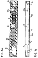
- FIGS. 1a and 1b of the accompanying drawing show an insert element suitable for the invention in plan view, Fig. 1b in side view in section.
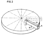
- Fig. 2 shows schematically how the insert element of Fig. 1 is placed on a suitable centrifuge rotor, e.g. is described in DE-OS 3 044 372, is applied by fastening means not shown here.
- a sample application chamber 31 is provided in a molded plastic body and is connected to different reagent fields I to VII 32.
- Each reagent field consists of a piece of absorbent carrier impregnated with a specific reagent, e.g. Paper or fleece.
- 33 and 33a are mixing valves I and II, 34 denotes the measuring point (cuvette).
- Fig. 1b shows the insert element of Fig. 1 a in side view.
- 35 denotes the plastic base body, 36 the sealing film is covered by the sample application chamber, reagent field mixing valves and measuring point.
- the sample is placed in the sample application chamber 31.
- a specific speed U1 is then set which is suitable for bringing the sample to the reagent field I32.
- the capillary force absorbs the solution, i.e. the solution is transported over the reagent field 32.
- the centrifugal force Z1 is less than the capillary force K1
- the solution remains in the field 32, provided that the absorption volume of the field is greater than the volume of the sample placed on it.
- the residence time of the solution in RI must be precisely defined.
- the centrifugal force is increased to Z2 so that Z2> K1 applies, the solution enriched with the reagent on RI leaves this field and comes into contact with the reagent field R II.
- the process is repeated here.
- the solution is distributed over R II, i.e. transported on.
- the conditions described above apply analogously.
- the process can be repeated any number of times, in which case reagent fields I to IV are run through.
- the insert elements can be designed differently and also have more or fewer reagent fields.
- the forces K n and Z n are practically freely selectable, which can be achieved in a technically very simple manner, in particular for the latter by the stepless adjustment of Z.
- the advantages of carrying out analysis procedures are that the time required for this is kept as short as possible. Therefore, the residence time of the solution on the reagent fields should be as short as possible.
- the mixing valve 33 has a boundary wall which is closed in the direction of the centrifugal force.
- a surface-active chamber for example a capillary, is arranged on the bottom, obliquely downward against the flow direction from the sample application chamber to the measuring point, which bends at its lower end and continues to the reagent field V.
- the centrifugal force Z3 is greater than the capillary crack in the bottom capillary K3, the liquid is held on the boundary wall.
- the capillary automatically draws the liquid out of the mixing space 33 into the associated capillary, whereby existing gradients are eliminated and the capillary force transports the liquid to the reagent field V.
- the capillary force therefore has an effect here the capillary of the mixing valve 33 always as a transport force when Z ⁇ K.
- the service life in the mixing valve 33 is again freely selectable by setting the condition Z M > K M.
- the condition for the transport is therefore exactly the opposite of the conditions described above.
- the mixing valve 33a is helpful to deliver a homogeneous solution into the cuvette 34.
- mixing is a complex process which e.g. by accelerating and braking the centrifuge strongly or by flowing air through the solution. According to the invention, this is avoided using technically simple means.
- K2 is a mechanical pressure force
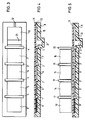
- FIG. 5 shows a device containing the anylysis element for carrying out the method according to the invention.
- FIG. 3 such an element is shown in supervision, in Fig. 4 in side view schematically.
- a suitable material e.g. Plastic molded body 8
- reagent carrier fields 5, 6, 7, which are inserted into the plastic body. These reagent carrier fields are covered by an elastic sealing film 11.
- a sample application chamber 9 contains an absorbent, inert, compressible material which, for example, can hold 15 .mu.l of liquid in the unloaded state and retains, for example, 2 .mu.l of liquid in the compressed state.
- a bulge in the body 8 serves as a measuring point or cuvette 21.
- the body 8 also has an overflow chamber 10 and a vent hole 12.
- Valve slots 1, 2, 3, 4 serve to receive valve stamps 17, 18, 19, 20, with which the individual reagent carrier fields can be separated from one another.
- pressure stamps 13, 14, 15, 16 are provided, the base area of which corresponds exactly to the area of the respective reagent carrier surface and which serve to compress filled reagent fields (FIG. 5).
- the sample is brought into the application chamber (9) by piercing the film 11 with a needle. An amount is injected such that the inert, absorbent fleece in the chamber 9 fills up completely, but does not give off a solution. Then e.g. by means of a suitable control device, the stamp 13 is pressed onto the field 9, so that the liquid has to leave this field and is transported into the field 5 by means of the capillary force. The cohesion of the liquid is practically completely transferred to FIG. 5.
- the valve plunger 17 is then e.g. also controlled by a suitable mechanism, pressed down so that 5 is separated from the application chamber 9.
- the film 11 adapts to the contours and serves as a sealing membrane.
- the test solution can be left in field 5 for a freely selectable time.
- the dry reagent in field 5 dissolves within a few seconds.
- the stamp 14 is pressed onto the field 5, so that the liquid has to leave this field and is transported into the field 6 via the capillary suction effect.
- the valve stamp 18 is pressed down, so that the contact to field 5 is interrupted. Again, the time for the removal or dissolution of the reagent can be freely selected in field 6 (which in turn is generally a matter of seconds).
- the absorbance change during a measured long enough can also be calculated from these signal changes using conventional methods.
- the measures available for carrying out the change in the 1st or 2nd force required for the method are primarily to be seen in the speed changes for the centrifugal force, and in the movement of pressure stamps for the mechanical pressure force.
- the interfacial force can also be regulated or changed by using surface-active agents.
- the polyoxyethylene derivatives are preferred as surface-active agents, but other nonionic detergents and anionic detergents, e.g. B. bile acid derivatives, or cationic detergents or mixtures thereof.
- analyzes which can be carried out according to the invention are those described in DE-OS 3,044,385.
- the method is particularly suitable for the determination of glucose, bilirubin, creatinine, albumin, protein, iron, hemoglobin, urea, uric acid, triglycerides, cholesterol, chloride, calcium, phosphate, ⁇ -GT, alkaline phosphates, GOT, GPT, lactate dehydrogenase, lipase , Amylase, creatine kinase, thyroid hormones, acid phosphatase, drugs, cancer indicators and coagulation factors, whereby in each case known reagents can be used for these determinations.
- Human serum samples were 1: 200 with bidist. Diluted water. 60 ⁇ l of this diluted solution were added to the sample application chamber 1.
- Alkaline phosphatase was determined on the insert element according to FIGS. 1 and 2.
- a human serum sample was 1:10 with bidist. Diluted water. 60 ⁇ l of this diluted solution were added to the sample application chamber 1.
- the recorded dependencies of the extinctions on time were evaluated using one of the usual methods in which the slope of the straight line is a measure of the activity of the enzyme to be determined.
- the unknown activities of alkaline phosphatase in the sample were determined after calibration of the method with a standard.
- the correlation with a comparison method, the one of the known manual techniques is good, as can be seen from FIG.
- Serum samples were 1:10 with bidist. Diluted water. 60 ⁇ l of this diluted solution were added to the sample application chamber 1.
- a human serum sample was 1:25 with bidist. Diluted water. 60 ⁇ l of this diluted solution were added to the sample application chamber 1.
- a human serum sample was 1: 200 with bidist. Diluted water. 60 ⁇ l of this diluted solution were added to the sample application chamber 1.
- Reagent carrier papers with a size of 6 ⁇ 6 ⁇ 0.3 mm are produced as follows: 10 .mu.l of the reagent solutions, which contain a quarter of the amount of substance as the different papers of the example in Example 1, are placed on a paper of the specified size. The solutions are completely absorbed; the solvent water is then removed from the papers by lyophilization.
- the sample is 1: 200 with bidist. Diluted water. 15 ul of this dilute solution are placed in the application chamber 9. Then the solution is brought onto the first reagent carrier 5 in the manner described above. Dwell time: 10 seconds. The solution is then brought from 5 to 6 in the manner already described. Residence time: 10 sec. In an analogous manner, the solution is placed on the reagent carrier 3 (7). Residence time: 5 sec. From there, the solution is brought into the cuvette 21 by slowly lowering the stamp 16. In it, the absorbance at 500 nm is tracked in a known manner as a function of time. The course of this curve can be used to determine the glucose concentration in unknown samples using the known “fixed-time-kinetic” method after calibration with a standard.
- Reagent carrier papers of size 6 ⁇ 6 ⁇ 0.3 mm are produced as follows: 10 ⁇ l of the reagent solutions, which contain exactly a quarter of the amount of substance as the different papers of Example 2, are placed on a paper of the specified size. The solutions are completely absorbed; the solvent water is then removed from the papers by lyophilization.
- the two papers are placed in the same order as in Example 2 on the first two positions of the analysis element of FIG. 3.
- a paper that does not contain any reagent is placed in the third position.
- the sample is 1:10 with bidist. Diluted water. 15 ⁇ l of this diluted solution are placed in the application chamber 9. Then the solution is brought onto the first reagent carrier 5 in the manner described. Dwell time: 10 seconds. The solution is then brought from 5 to 6 in the manner already described. Residence time: 10 sec. The solution is applied to the blanket 7 in an analogous manner. Residence time: 5 sec. From there, the solution is brought into the cuvette 21 by slowly lowering the stamp 16. In it, the absorbance at 410 nm is tracked as a function of time. The activity of the alkaline phosphatase in unknown samples can be determined from the course of the recorded straight line using known kinetic determination methods after calibration with a standard.
- Reagent carrier papers of size 6 ⁇ 6 ⁇ 0.3 mm are produced as follows: 10 ⁇ l of the reagent solutions, which contain exactly a quarter of the amount of substance as the different papers of Example 4, were placed on a paper of the specified size. The solutions are completely absorbed; the solvent water was then removed from the papers by lyophilization.
- the two papers were placed in the same order as in Example 4 on the first two positions of the analysis element of FIG. 3.
- the sample was 1:25 with bidist. Diluted water. 15 ul of this diluted solution were placed in the application chamber 9. Then the solution is brought onto the first reagent carrier 5 in the manner described. Residence time: 10 sec. The solution was then brought from 5 to 6 in the manner already described. Residence time: 10 sec. The solution was moved to field 7 in an analogous manner. Residence time: 5 sec. From there, the solution is brought into the cuvette 21 by slowly lowering the stamp 16. In it, the absorbance at 340 nm is monitored in a known manner as a function of time. After a curved initial phase, this function was linear. This part is made using known evaluation methods for kinetic methods after calibration with a standard, the activity of creatine kinase in an unknown sample is determined.
Abstract
Description
Die Erfindung betrifft ein Verfahren zur Durchführung analytischer Bestimmungen durch Mischen und Inkubieren einer Probelösung mit wenigstens einem Reagenz und Messung eines Parameters im Reaktionsgemisch und ein hierfür geeignetes Mittel.The invention relates to a method for carrying out analytical determinations by mixing and incubating a sample solution with at least one reagent and measurement of a parameter in the reaction mixture and to a means suitable for this.
Die Verwendung von Trockenreagentien auf geeigneten inerten Trägermaterialien ist ein seit langem bekanntes Hilfsmittel bei der Durchführung chem. Reaktionen, die zum qualitativen oder quantitativen Nachweis einer zu analysierenden Substanz herangezogen werden können. Als Beispiele seien genannt: DE-AS 2 332 760, DE-OS 2 717 817, EPA 0 014 797, DE-OS 2 752 352, DE-OS 2 927 345. Diesen Verfahren ist gemeinsam, dass die in Lösung befindliche Probe auf den Reagenzträger gegeben wird. Von seinem Auftragsort diffundiert die Probe dann unter Einwirkung von Kapillarkräften in den Träger.The use of dry reagents on suitable inert carrier materials is a long-known tool in the implementation of chem. Reactions that can be used for the qualitative or quantitative detection of a substance to be analyzed. Examples include: DE-AS 2 332 760, DE-OS 2 717 817, EPA 0 014 797, DE-OS 2 752 352, DE-OS 2 927 345. These methods have in common that the sample in solution is the reagent carrier is given. The sample then diffuses from its place of application into the carrier under the action of capillary forces.
Auf dem Weg werden Reagentien ganz oder teilweise aufgelöst, die auf diese Weise gebildete Reagenz-Probelösung wandert weiter, bis sie schliesslich zu einer Messzone gelangt, wo die Farbintensitätsänderung optisch vermessen wird. Die Messzone ist jeweils integraler Bestandteil des Reagenzträgers.All or part of the reagents are dissolved on the way, the reagent sample solution formed in this way moves on until it finally reaches a measuring zone, where the change in color intensity is measured optically. The measuring zone is an integral part of the reagent carrier.
Wie nun z.B. aus der DE-OS 2 927 345 zu entnehmen ist, werfen Verfahren, bei denen die Diffusionsprozesse ungesteuert ablaufen und bei denen die Remission von Lichtstrahlen direkt auf dem Reagenzträger, der im allgemeinen aus einer opaken Schicht besteht, gemessen wird, beträchtliche Probleme auf. Fasermaterialien zeigen Unregelmässigkeiten, die im Mikrobereich zu unterschiedlichen Ausbreitungsgeschwindigkeiten der Flüssigkeiten führen, es entstehen Zonen mit höheren oder niedrigeren Reagenzkonzentrationen als sie optimal sind. So wird z.B. in der EPA 0 014 797 erwähnt, dass «Lufttaschen» in den Trägermaterialien zu zusätzlichen Schwierigkeiten führen und die Schlussfolgerung gezogen, dass Flüssigkeitsströme, die durch Kapillarkräfte erzeugt werden, «kontrolliert» werden müssen.How now e.g. from DE-OS 2 927 345, processes in which the diffusion processes run uncontrolled and in which the reflectance of light rays are measured directly on the reagent carrier, which generally consists of an opaque layer, pose considerable problems. Fiber materials show irregularities, which in the micro range lead to different rates of spreading of the liquids, zones with higher or lower reagent concentrations than are optimal. For example, mentioned in EPA 0 014 797 that "air pockets" in the carrier materials lead to additional difficulties and that the conclusion drawn that liquid flows generated by capillary forces must be "controlled".
Der zweite wesentliche Nachteil liegt in der Remissionsmessung selbst:
im Gegensatz zur Durchlicht-Fotometrie gibt es hier keine lineare Beziehung zwischen der Konzentration einer lichtabsorbierenden Substanz und der Extinktion. Man erhält mehr oder weniger stark gekrümmte Eichkurven, in die die Oberflächeneigenschaften stark mit eingehen. Darin ist ein grundsätzlicher Nachteil zu sehen, der die Reproduzierbarkeit eines analytischen Auswerteverfahrens stark negativ beeinflusst. Ausserdem können damit Tests, die auf der Messung von sich bildenden oder abnehmenden Trübungen (turbidimetrische Verfahren) beruhen, grundsätzlich nicht durchgeführt werden. Diese stellen aber bei immunologischen Methoden und auch bei Enzymbestimmungen wie der Lipase-Bestimmung eine weit verbreitete zuverlässige Technik dar.The second major disadvantage is the remission measurement itself:
In contrast to transmitted-light photometry, there is no linear relationship between the concentration of a light-absorbing substance and the extinction. You get more or less strongly curved calibration curves, in which the surface properties are strongly influenced. This is a fundamental disadvantage that has a very negative impact on the reproducibility of an analytical evaluation process. In addition, tests based on the measurement of turbidity or turbidity (turbidimetric methods) cannot be carried out. However, these represent a widespread reliable technique in immunological methods and also in enzyme determinations such as lipase determination.
Ein weiterer Nachteil solcher Analysenelemente ist darin zu sehen, dass unterschiedliche Reaktionsphasen bei mehrstufiger Reaktion auf getrennten Schichten der Analysenelemente nicht gezielt angesteuert werden können. Das heisst, die Startzeitpunkte von Folgereaktionen hängen von der nicht konstanten Diffusionsgeschwindigkeit der Lösung ab.Another disadvantage of such analysis elements is that different reaction phases cannot be controlled in a targeted manner in a multi-stage reaction to separate layers of the analysis elements. This means that the starting times of subsequent reactions depend on the non-constant diffusion rate of the solution.
Auch in der schichtenförmigen Anordnung selbst ist ein Nachteil zu sehen, da die Berührungsflächen von Reagenzien, die sich in bezug auf ihre Stabilität ungünstig beeinflussen können, relativ gross sind. Günstiger wäre es, solche Reagenzien streng getrennt voneinander in einem Reagenzträger anzuordnen.A disadvantage can also be seen in the layered arrangement itself, since the contact surfaces of reagents, which can adversely affect their stability, are relatively large. It would be cheaper to arrange such reagents strictly separate from each other in a reagent carrier.
Aus obigem geht hervor, dass es im Sinne der Erzielung von Analysenergebnissen mit maximaler Richtigkeit und Reproduzierbarkeit notwendig ist, die genannten Nachteile zu vermeiden, da sie dem Anwendungsbereich solcher «Analysenelemente», die aus Reagenzträgern aufgebaut sind, relativ enge Grenzen setzen.The above shows that in order to achieve analytical results with maximum accuracy and reproducibility, it is necessary to avoid the disadvantages mentioned, since they place relatively narrow limits on the scope of such «analytical elements», which are made up of reagent carriers.
Aus der Sicht des Benutzers sind solche Testdurchführungstechniken jedoch insofern vorteilhaft, als sie eine sehr einfache Handhabung erlauben, da keine Reagenzlösungen angesetzt werden müssen, da das Pipettieren von Reagenz entfällt, keine Stabilitätsprobleme mit den in Lösung immer instabileren Reagenzien auftreten usw.From the user's point of view, however, such test execution techniques are advantageous in that they allow very simple handling, since no reagent solutions have to be prepared, since there is no need to pipette reagent, there are no stability problems with the reagents, which are increasingly unstable in solution, etc.
Aus DE-OS 1 944 246 ist es bekannt, aus einer Probelösung mit Hilfe eines speziellen Filtermittels ausgefällte Substanzen wie z.B. Eiweiss, unter Anwendung von Zentrifugalkräften abzutrennen. Aus DE-OS 2 536 886 ist ein Verfahren zur Analyse von Bestandteilen einer flüssigen Probe auf einem Fasermedium bekannt, bei dem auf dem Fasermedium an der Analysenstelle ein reproduzierbarer Kompressionszustand aufrechterhalten wird.From DE-OS 1 944 246 it is known to precipitate substances from a sample solution with the aid of a special filter medium, e.g. Protein to be separated using centrifugal forces. DE-OS 2 536 886 discloses a method for analyzing constituents of a liquid sample on a fiber medium, in which a reproducible compression state is maintained on the fiber medium at the analysis point.
In EPA 0 039 825 wird ein Küvettenrotor für ein Analysegerät und dessen Verwendung beschrieben. Dabei wird eine Flüssigkeit zur genauen Dosierung in Abmeßräume gebracht, die dann durch Erhöhung der Zentrifugalkraft in die Meßküvetten transportiert wird. Die Kapillaren dienen dabei nicht einem Transport der Flüssigkeit, sondern nur dem genauen Dosieren.EPA 0 039 825 describes a cuvette rotor for an analysis device and its use. Here, a liquid is brought into metering rooms for precise dosing, which is then transported into the measuring cuvettes by increasing the centrifugal force. The capillaries do not serve to transport the liquid, but only for precise dosing.
Der Erfindung liegt nun die Aufgabe zugrunde, diese Vorteile beizubehalten und gleichzeitig die geschilderten Nachteile zu beseitigen.The invention is based on the object of maintaining these advantages and at the same time eliminating the disadvantages described.
Gelöst wird diese Aufgabe erfindungsgemäss durch ein Verfahren zur Durchführung analytischer Bestimmungen durch Mischen und Inkubieren einer Probelösung mit wenigstens einem Reagenz und Messung eines Parameters im Reaktionsgemisch, wobei die Probelösung von einer Aufgabestelle zu einer Messstelle transportiert wird, welches dadurch gekennzeichnet ist, dass man die Probelösung zuerst zu einem löslichen Trockenreagenz transportiert unter wenigstens teilweiser Auflösung des letzteren und dann zur Messstelle weitertransportiert und der Transport duch zwei verschiedene Kräfte erfolgt, wobei er wenigstens auf einem Teil der Transportstrecke durch eine auf die Lösung wirkende Grenzflächenkraft als erste Kraft bewirkt wird, der zur Regelung der Transportgeschwindigkeit oder Transportrichtung als zweite Kraft eine Zentrifugalkraft oder mechanische Druckkraft überlagert wird, die je nachdem, welcher Transportzustand der Flüssigkeit eingestellt werden soll, grösser oder keiner als die erste Kraft gemacht wird.This object is achieved according to the invention by a method for carrying out analytical determinations by mixing and incubating a sample solution with at least one reagent and measuring a parameter in the reaction mixture, the sample solution being transported from a feed point to a measuring point, which is characterized in that the sample solution first transported to a soluble dry reagent with at least partial dissolution of the latter and then transported on to the measuring point and the transport is carried out by two different forces, being effected at least on part of the transport route by an interface force acting on the solution as the first force, which is used for regulation the transport speed or direction of transport is superimposed as a second force on a centrifugal force or mechanical pressure force which, depending on the transport state of the liquid, is greater or none than d he first force is made.
Das neue Verfahren verbindet die Vorteile der geschilderten Reagenzträgertechnik mit der Genauigkeit und Fehlerfreiheit üblicher nasschemischer Verfahren.The new process combines the advantages of the described reagent carrier technology with the accuracy and accuracy of conventional wet chemical processes.
Erreicht wird dies dadurch, dass die zu analysierende Probelösung (im allgemeinen mit Wasser verdünnt) in eine Eingabestelle gegeben wird, von der aus sie auf dem Weg zu einer Messstelle einen oder mehrere Träger von Trockenreagenz durchströmt, wobei die Reagenzien ganz oder teilweise gelöst werden. Das Durchströmen geschieht unter strenger Kontrolle der Fliessgeschwindigkeiten und damit der Fliesszeiten, indem der treibenden Grenzflächenkraft eine zweite Kraft überlagert wird, die den Strom beschleunigen, bremsen oder anhalten kann. Am Ende des Strömungsweges gelangt die Flüssigkeit dann an eine Messstelle, die nicht mit dem Reagenzträger identisch ist, in der ein Reaktionssignal, vorzugsweise die optische Transmission, gemessen wird.This is achieved by placing the sample solution to be analyzed (generally diluted with water) in an input point from which flows through them on the way to a measuring point through one or more carriers of dry reagent, the reagents being wholly or partially dissolved. The flow occurs under strict control of the flow velocities and thus the flow times by superimposing the driving interface force on a second force that can accelerate, brake or stop the flow. At the end of the flow path, the liquid then reaches a measuring point, which is not identical to the reagent carrier, in which a reaction signal, preferably the optical transmission, is measured.
Als Reagenzien kommen dabei einerseits solche in Frage, die vom Trägermaterial ganz oder teilweise abgelöst werden können, z.B. Puffersubstanzen, Salze, Enzyme oder deren Substrate, andererseits solche, die am Trägermaterial adsorbtiv oder kovalent gebunden sind und an denen dann eine «Festphasen-Reaktion» stattfinden kann, beispielsweise Ionenaustauscher, trägergebundene biologisch aktive Substanzen wie Enzyme, Antikörper oder Antigene und ähnliche.On the one hand, the reagents that can be used are those that can be completely or partially detached from the carrier material, e.g. Buffer substances, salts, enzymes or their substrates, on the other hand those that are adsorptively or covalently bound to the carrier material and to which a “solid phase reaction” can then take place, for example ion exchangers, carrier-bound biologically active substances such as enzymes, antibodies or antigens and the like.
Für die Messung eines Reaktionssignals eignen sich z.B. ausser der schon erwähnten optischen Transmission je nach Ausführungsform der Messstelle auch Elektrodenpotentiale, elektrische Leitfähigkeit, Fluoreszenzstrahlung usw.For the measurement of a reaction signal, e.g. In addition to the optical transmission already mentioned, depending on the embodiment of the measuring point, electrode potentials, electrical conductivity, fluorescent radiation, etc.
Im folgenden wird die Erfindung unter Bezugnahme auf die Zeichnung näher beschrieben. In dieser stellen dar:
- Fig. 1 a und 1b Oben- bzw. Seitenansicht eines für die Erfindung geeigneten Einsatzelementes,
- Fig. 2 Darstellung des Elementes von Fig. 1 a und 1b auf dem Rotor,
- Fig. 3, 4 und 5 Ansichten eines anderen Analysenelementes zur Durchführung der Erfindung,
- Fig. 6, 7, 8, 9 und 10 erfindungsgemäss erhaltene Analysenresultate in graphischer Darstellung.
- 1a and 1b top and side view of an insert element suitable for the invention,
- 2 representation of the element of Fig. 1 a and 1b on the rotor,
- 3, 4 and 5 views of another analysis element for carrying out the invention,
- 6, 7, 8, 9 and 10 analysis results obtained according to the invention in a graphical representation.
Je nach den überlagerten Kräften (K₂) gibt es im wesentlichen zwei Ausführungsformen der Erfindung, wobei die treibenden Kräfte (K₁) jeweils Grenzflächen- bzw. Kapillarkräfte sind.Depending on the superimposed forces (K₂), there are essentially two embodiments of the invention, the driving forces (K₁) being interfacial and capillary forces, respectively.
Bei der ersten Ausführungsform ist K₂ eine Zentrifugalkraft.In the first embodiment, K₂ is a centrifugal force.
Bei diesem Analysensystem werden austauschbare Einsatzelemente für Zentrifugalanalysenrotoren, die beispielsweise aus einem Plastikformkörper aus Polystyrol, Plexiglas, Polyurethan u. ä. sowie Reagenzträgerfeldern, die aus einem saugfähigen Trägermaterial, das mit dem Reagenz imprägniert ist, oder anderen kleinen reagenzgefüllten Hohlräumen (z. B. einer Oberflächenstruktur im Plastikkörper), die in den Plastikkörper eingelegt sind, und einer Verschliessfolie bestehen, so auf einen Rotor einer Zentrifuge gesteckt, dass die flüssigkeitsbewegende Kapillarkraft von der Zentrifugalkraft gesteuert werden kann. Hierzu ist notwendig, dass verschiedene Drehzahlen und damit Zentrifugalkräfte eingestellt werden können.In this analysis system, interchangeable insert elements for centrifugal analysis rotors are made, for example, from a molded plastic body made of polystyrene, plexiglass, polyurethane and the like. Ä. As well as reagent carrier fields, which consist of an absorbent carrier material that is impregnated with the reagent, or other small reagent-filled cavities (e.g. a surface structure in the plastic body), which are inserted into the plastic body, and a sealing film, so on a rotor a centrifuge, that the liquid moving capillary force can be controlled by the centrifugal force. For this it is necessary that different speeds and thus centrifugal forces can be set.
Der Analysenablauf bei dieser Ausführungsform der Erfindung wird anhand der Figuren 1a und 1b der beigefügten Zeichnung näher beschrieben. Fig. 1a zeigt ein für die Erfindung geeignetes Einsatzelement in der Aufsicht, Fig. 1b in der Seitenansicht im Schnitt.The course of the analysis in this embodiment of the invention is described in more detail with reference to FIGS. 1a and 1b of the accompanying drawing. Fig. 1a shows an insert element suitable for the invention in plan view, Fig. 1b in side view in section.
Fig. 2 stellt schematisch dar, wie das Einsatzelement von Fig. 1 auf einem geeigneten Zentrifugenrotor, wie er z.B. in der DE-OS 3 044 372 beschrieben ist, durch hier nicht gezeigte Befestigungsmittel aufgebracht ist.Fig. 2 shows schematically how the insert element of Fig. 1 is placed on a suitable centrifuge rotor, e.g. is described in DE-OS 3 044 372, is applied by fastening means not shown here.
Wie in Fig. 1 a gezeigt, ist in einem Plastikformkörper eine Probenauftragskammer 31 vorgesehen, die mit verschiedenen Reagenzfeldern I bis VII 32 in Verbindung steht. Jedes Reagenzfeld besteht aus einem mit einem bestimmten Reagenz imprägnierten Stück saugfähigen Träger, wie z.B. Papier oder Vlies. 33 und 33a sind Mischventile I und II, 34 bezeichnet die Messstelle (Küvette). Fig. 1b zeigt das Einsatzelement von Fig. 1 a in Seitenansicht. 35 bezeichnet den Plastikgrundkörper, 36 die Verschliessfolie durch die Probenauftragskammer, Reagenzfeldermischventile und Messstelle abgedeckt sind.As shown in FIG. 1 a, a
Die Durchführung des Verfahrens der Erfindung wird nun unter Bezugnahme auf Fig. 1 und 2 näher beschrieben.The implementation of the method of the invention will now be described in more detail with reference to FIGS. 1 and 2.
Die Probe wird in die Probenauftragskammer 31 gegeben. Dann wird eine bestimmte Drehzahl U1 eingestellt, die geeignet ist, die Probe an das Reagenzfeld I32 heranzuführen. Sobald der Kontakt hergestellt ist, saugt die Kapillarkraft die Lösung auf, d.h. die Lösung wird über das Reagenzfeld 32 transportiert. Ist die Zentrifugalkraft Z1 kleiner als die Kapillarkraft K1, bleibt die Lösung, sofern das Aufnahmevolumen des Feldes grösser ist als das Volumen der aufgegebenen Probe, in dem Feld 32. Mit der Bedingung Z1 < K1 ist also die Verweilzeit der Lösung in RI genau festzulegen. Vergrössert man nun die Zentrifugalkraft auf Z2, so dass Z2 > K1 gilt, verlässt die um das auf RI befindliche Reagenz angereicherte Lösung dieses Feld und tritt mit dem Reagenzfeld R II in Kontakt. Hier wiederholt sich der Vorgang. Die Lösung wird über R II verteilt, d.h. weitertransportiert. In Analogie gelten die oben beschriebenen Bedingungen.The sample is placed in the
Der Vorgang lässt sich beliebig oft wiederholen, wobei im hier skizzierten Fall Reagenzfelder I bis IV durchlaufen werden. Natürlich können die Einsatzelemente anders gestaltet sein und auch mehr oder weniger Reagenzfelder aufweisen. Die Kräfte Kn und Zn sind praktisch frei wählbar, was vor allem für letztere durch die stufenlose Einstellung von Z technisch sehr einfach realisiert werden kann. Die Durchführung von Analysenverfahren gewinnt dadurch an Vorteilen, dass man die dazu benötigte Zeit so kurz wie möglich hält. Deshalb sollte auch die Verweilzeit der Lösung auf den Reagenzfeldern so kurz wie möglich sein. Es ist möglich, die Zentrifugalkraft Z so gross zu wählen, dass die Lösung von den Kapillarkräften nur gebremst wird, d.h. die Lösung kommt nicht zum Stehen, sondern wandert mit von der Kraft Zn - Kn hervorgerufener Geschwindigkeit durch die entsprechenden Reagenzfelder. Findet dieser Vorgang in Sekunden oder Sekundenbruchteilen statt, so ist es leicht möglich, dass sich an der Lösungsfront höhere Reagenzkonzentrationen einstellen, d.h. in Richtung Zentrifugalkraft baut sich über das Lösungsvolumen ein Konzentrationsanstieg auf.The process can be repeated any number of times, in which case reagent fields I to IV are run through. Of course, the insert elements can be designed differently and also have more or fewer reagent fields. The forces K n and Z n are practically freely selectable, which can be achieved in a technically very simple manner, in particular for the latter by the stepless adjustment of Z. The advantages of carrying out analysis procedures are that the time required for this is kept as short as possible. Therefore, the residence time of the solution on the reagent fields should be as short as possible. It is possible to choose the centrifugal force Z so large that the solution is only slowed down by the capillary forces, ie the solution does not come to a standstill, but moves through the corresponding reagent fields at a speed caused by the force Z n - K n . If this process takes place in seconds or fractions of a second, it is easily possible that higher reagent concentrations occur on the solution front, ie in the direction of the centrifugal force an increase in concentration builds up over the solution volume.
Zur Einhaltung definierter Reaktionsbedingungen gehört es jedoch, einheitliche Konzentrationsverhältnisse - wenn nötig - einzustellen. Um derartige Inhomogenitäten zu beseitigen, wird erfindungsgemäss ein sogenanntes Mischventil 33 vorgesehen. Das Mischventil 33 weist eine in Richtung der Zentrifugalkraft geschlossene Begrenzungswand auf. Am Boden ist eine schräg nach unten entgegen der Strömungsrichtung von Probenauftragskammer zu Messstelle angeordnete grenzflächenaktive Kammer, z.B. Kapillare angeordnet, welche an ihrem unteren Ende umbiegt und zum Reagenzfeld V weiterführt. Solange die Zentrifugalkraft Z3 grösser ist als die Kapillarkrak in der Bodenkapillare K3, wird die Flüssigkeit an der Begrenzungswand festgehalten. Senkt man Z3 unter den Wert von K3, so saugt die Kapillare die Flüssigkeit selbständig aus dem Mischraum 33 in die zugehörige Kapillare ab, wobei vorher bestehende Gradienten beseitigt werden und die Kapillarkraft transportiert die Flüssigkeit zum Reagenzfeld V. Allgemein ausgedrückt wirkt daher hier die Kapillarkraft in der Kapillare des Mischventils 33 immer als Transportkraft, wenn Z < K ist.To maintain defined reaction conditions, however, it is necessary to set uniform concentration ratios, if necessary. To such To eliminate inhomogeneities, a so-called
Die Standzeit im Mischventil 33 ist wiederum frei wählbar durch die Einstellung der Bedingung ZM > KM. Die Bedingung für den Transport ist also genau umgekehrt zu den oben beschriebenen Bedingungen.The service life in the mixing
Die weiteren Schritte über die Reagenzfelder V bis VII und über das Mischventil II 33a brauchen nicht erneut beschrieben werden, sie ergeben sich aus Analogiebetrachtungen zu den vorigen Schritten. In der erläuterten Ausführungsform ist das Mischventil 33a hilfreich, um eine homogene Lösung in die Küvette 34 zu befördern. In bekannter Ausführungsformen von Zentrifugalanalyzern ist das Mischen ein aufwendiger Vorgang, der z.B. durch starkes Beschleunigen und Abbremsen der Zentrifuge oder das Durchströmen der Lösung mit Luft bewirkt wird. Dies wird erfindungsgemäss mit technisch einfachen Mitteln vermieden.The further steps via the reagent fields V to VII and via the mixing valve II 33a do not need to be described again, they result from considerations of analogy to the previous steps. In the illustrated embodiment, the mixing valve 33a is helpful to deliver a homogeneous solution into the
Bei der zweiten Ausführungsform der Erfindung ist K₂ eine mechanische Druckkraft.In the second embodiment of the invention, K₂ is a mechanical pressure force.
In den Fig. 3 und 4 der Zeichnung werden für diese Ausführungsform geeignete Mittel in Form von wegwerfbaren Analysenelementen dargestellt. In Fig. 5 wird eine das Anylysenelement enthaltende Vorrichtung zur Durchführung des erfindungsgemässen Verfahrens dargestellt.3 and 4 of the drawing, suitable means for this embodiment are shown in the form of disposable analysis elements. 5 shows a device containing the anylysis element for carrying out the method according to the invention.
In Fig. 3 ist ein derartiges Element in Aufsicht, in Fig. 4 in der Seitenansicht schematisch dargestellt. Der aus einem geeigneten Material, wie z.B. Plastik bestehende Formkörper 8 weist Reagenzträgerfelder 5, 6, 7 auf, die in den Plastikkörper eingelegt sind. Durch eine elastische Verschliessfolie 11 sind diese Reagenzträgei felder abgedeckt. Eine Probenauftragskammer 9 enthält ein saugfähiges inertes zusammenpressbares Material, das beispielsweise in entlastetem Zustand 15 µl Flüssigkeit aufnehmen kann und im zusammengepressten Zustand beispielsweise 2 µl Flüssigkeit zurückhält. Eine Ausbuchtungen im Körper 8 dient als Messstelle bzw. Küvette 21. Der Körper 8 weist ausserdem eine Überlaufkammer 10 und eine Entlüftungsbohrung 12 auf.In Fig. 3 such an element is shown in supervision, in Fig. 4 in side view schematically. Made of a suitable material, e.g. Plastic molded
Ventilschlitze 1, 2, 3, 4 dienen zur Aufnahme von Ventilstempeln 17, 18, 19, 20, mit denen die einzelnen Reagenzträgerfelder voneinander getrennt werden können. Ausserdem sind Durckstempel 13, 14, 15, 16 vorgesehen, deren Grundfläche genau der Fläche der jeweiligen Reagenzträgerfläche entspricht und die dazu dienen, gefüllte Reagenzfelder zusammenzudrücken (Fig. 5).
Der Verfahrensablauf bei dieser Ausführungsform der Erfindung ist folgendermassen:The procedure in this embodiment of the invention is as follows:
Die Probe wird in die Auftragskammer (9) gebracht, indem die Folie 11 mit einer Nadel durchstochen wird. Es wird eine solche Menge injiziert, dass sich das inerte, saugfähige Vlies in der Kammer 9 vollständig füllt, aber keine Lösung abgibt. Anschliessend wird z.B. durch eine geeignete Steuerungsvorrichtung, der Stempel 13 auf das Feld 9 gedrückt, so dass die Flüssigkeit dieses Feld verlassen muss und mittels der Kapillarkraft in das Feld 5 transportiert wird. Über die Kohäsion der Flüssigkeit wird diese praktisch vollständig nach 5 überführt. Anschliessend wird der Ventilstempel 17 z.B. ebenfalls über einen geeigneten Mechanismus gesteuert, heruntergedrückt, so dass 5 von der Auftragskammer 9 abgetrennt ist. Die Folie 11 passt sich jeweils den Konturen an und dient als Dichtmembran. Die Probelösung kann eine frei wählbare Zeit lang im Feld 5 stehen gelassen werden. In der Regel löst sich allerdings das im Feld 5 befindliche Trockenreagenz innerhalb weniger Sekunden. Im nächsten Schritt wird der Stempel 14 auf das Feld 5 gedrückt, so dass die Flüssigkeit dieses Feld verlassen muss und über die kapillare Ansaugwirkung des Feldes 6 in dieses hineintransportiert wird. Danach wird der Ventilstempel 18 heruntergedrückt, so dass der Kontakt zu Feld 5 unterbrochen ist. Wiederum kann die Zeit zur Ab- oder Auflösung des Reagenz in Feld 6 frei gewählt werden (wobei es sich wiederum im allgemeinen um Sekunden dauernde Vorgänge handelt).The sample is brought into the application chamber (9) by piercing the
Sollte sich bei dem Flüssigkeitstransport durch Kapillarkräfte und bei dem Einströmen in das Reagenzfeld ein Konzentrationsgradient aufbauen, kann dieser dadurch beseitigt werden, dass man vor den Weitertransport nach Feld 7 einen Mischvorgang einschaltet. Durch Andrücken des Ventilstempels 19, Abheben des Ventilstempels 18 und des Stempels 14 und Andrücken des Stempels 15, wird die Flüssigkeit nach Feld 5 zurücktransportiert. Durch Anheben von Stempel 15 und Andrücken von Stempel 14 wird die Flüssigkeit wieder nach Feld 6 zurückbefördert. Gegebenenfalls kann diese Vor-Rück-Bewegung mehrere Male wiederholt werden. Zum Schluss wird dann wieder der Zustand hergestellt: Stempel 14 angedrückt, Ventilstempel 18 angedrückt.If a concentration gradient builds up when the liquid is transported by capillary forces and when it flows into the reagent field, this can be eliminated by switching on a mixing process before moving on to field 7. By pressing the
Der Weitertransport der Flüssigkeit von Feld 6 nach Feld 7 erfolgt nach gegebenenfalls Abheben von Ventilstempel 19 in analoger Weise durch Andrücken von Ventilstempel 18 und Andrücken von Stempel 15. Gegebenenfalls kann der Mischvorgang zwischen Feld 6 und Feld 7 in Analogie zur beschriebenen Weise unter Benutzung von Ventilstempel 20 wiederholt werden.The further transport of the liquid from
Nach Auflösen des Reagenz in Feld 7 wird sie so entstandene Lösung dann durch Andrücken von Ventilstempel 19 und Andrücken von Stempel 15 in die Küvette 21 gedrückt.After dissolving the reagent in field 7, the solution thus obtained is then pressed into the
Danach wird in geeigneter Weise in einem üblichen Verfahren die Extinktionsänderung während einer genügend langen Zeit gemessen. Aus dieser Signaländerungen kann ebenfalls mit üblichen Methoden die Konzentration der zu analysierenden Substanz berechnet werden.The absorbance change during a measured long enough. The concentration of the substance to be analyzed can also be calculated from these signal changes using conventional methods.
Die für die Durchführung der für das Verfahren erforderliche Änderung der 1. bzw. 2. Kraft zur Verfügung stehenden Massnahmen sind für die Zentrifugalkraft in erster Linie in Drehzahländerungen, für die mechanische Druckkraft in Bewegung von Druckstempeln zu sehen. Die Grenzflächenkraft kann ausser durch die Oberflächengestaltung auch durch Einsatz oberflächenaktiver Mittel geregelt bzw. verändert werden. Als oberflächenaktive Mittel werden die Polyoxyäthylenderivate bevorzugt, jedoch können auch andere nichtionische Detergentien sowie anionische Detergentien, z. B. Gallensäurederivate, oder kationische Detergentien oder Gemische davon verwendet werden.The measures available for carrying out the change in the 1st or 2nd force required for the method are primarily to be seen in the speed changes for the centrifugal force, and in the movement of pressure stamps for the mechanical pressure force. In addition to the surface design, the interfacial force can also be regulated or changed by using surface-active agents. The polyoxyethylene derivatives are preferred as surface-active agents, but other nonionic detergents and anionic detergents, e.g. B. bile acid derivatives, or cationic detergents or mixtures thereof.
Beispiele für erfindungsgemäss durchführbare Analysen sind die in der DE-OS 3 044 385 beschriebenen. Insbesondere eignet sich das Verfahren zur Bestimmung von Glucose, Bilirubin, Creatinin, Albumin, Eiweiss, Eisen, Hemoglobin, Harnstoff, Harnsäure, Triglyceriden, Cholesterin, Chlorid, Kalzium, Phosphat, γ-GT, alkalischer Phosphate, GOT, GPT, Lactatdehydrogenase, Lipase, Amylase, Creatinkinase, Schilddrüsenhormonen, saure Phosphatase, Drogen, Krebsindikatoren und Gerinnungsfaktoren, wobei jeweils für diese Bestimmungen an sich bekannte Reagenzien eingesetzt werden können.Examples of analyzes which can be carried out according to the invention are those described in DE-OS 3,044,385. The method is particularly suitable for the determination of glucose, bilirubin, creatinine, albumin, protein, iron, hemoglobin, urea, uric acid, triglycerides, cholesterol, chloride, calcium, phosphate, γ-GT, alkaline phosphates, GOT, GPT, lactate dehydrogenase, lipase , Amylase, creatine kinase, thyroid hormones, acid phosphatase, drugs, cancer indicators and coagulation factors, whereby in each case known reagents can be used for these determinations.
Die folgenden Beispiele erläutern die Erfindung weiter:The following examples further illustrate the invention:
Glucosebestimmung unter Verwendung des Einsatzelementes gemäss Fig. 1 und 2.Determination of glucose using the insert element according to FIGS. 1 and 2.
Auf Filterpapiere der Grösse 6 × 6 mm und der Dicke 0,3 mm wurden folgende Reagenzien aufgebracht und wie aus Fig. 1 ersichtlich, im beschriebenen Einsatzelement positioniert:

Humanserumproben wurden 1 : 200 mit bidest. Wasser verdünnt. Von dieser verdünnten Lösung wurden 60 µl in die Probenauftragskammer 1 gegeben.Human serum samples were 1: 200 with bidist. Diluted water. 60 μl of this diluted solution were added to the sample application chamber 1.
Es wurde bei 25°C nach folendem Programm zentrifugiert:


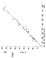
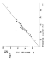
Die Änderung der Extinktion in Abhängigkeit von der Zeit wurde gemessen und nach einem der üblichen «Fixed-time-kinetischen Verfahren» ausgewertet. Die unbekannten Konzentrationen an Glucose in der Probe wurden nach Eichung des Verfahrens mit einem Standard bestimmt. Die Übereinstimmung mit einer Vergleichsmethode, der eine der bekannten manuellen Techniken zugrunde liegt, ist sehr gut, wie aus Fig. 6 zu erkennen ist, welche die Ergebnisse der Vergleichsmethode auf der Abscisse, der erfindungsgemässen Methode auf der Ordinate zeigt.The change in absorbance as a function of time was measured and evaluated using one of the usual “fixed-time kinetic methods”. The unknown concentrations of glucose in the sample were determined after calibration of the method with a standard. The agreement with a comparison method on which one of the known manual techniques is based is very good, as can be seen from FIG. 6, which shows the results of the comparison method on the abscissa, the method according to the invention on the ordinate.
Auf der Ordinate sind auch in den folgenden Beispielen die Werte mit der erfindungsgemässen Methode aufgetragen (Symbol ZF).The values are also plotted on the ordinate in the following examples using the method according to the invention (symbol ZF).
Alkalische Phosphatase wurde auf dem Einsatzelement gemäss Fig. 1 und 2 bestimmt.Alkaline phosphatase was determined on the insert element according to FIGS. 1 and 2.
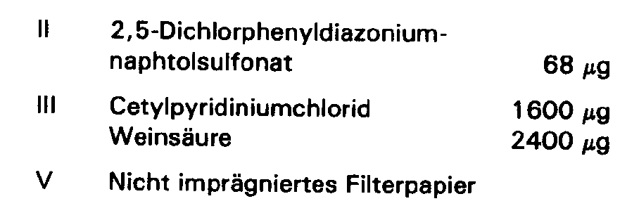
Auf Filterpapiere der Grösse 6 × 6 mm und der Dicke 0,3 mm wurden folgende Reagenzien aufgebracht und wie aus Fig. 1 ersichtlich, positioniert:
Eine Humanserumprobe wurde 1 : 10 mit bidest. Wasser verdünnt. Von dieser verdünnten Lösung wurden 60 µl in die Probenauftragskammer 1 gegeben.A human serum sample was 1:10 with bidist. Diluted water. 60 μl of this diluted solution were added to the sample application chamber 1.
Es wurde bei 37°C nach folgendem Programm zentrifugiert:

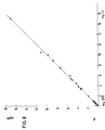
Die aufgezeichneten Abhängigkeiten der Extinktionen von der Zeit wurden nach einem der üblichen Verfahren, bei denen die Steigung der Geraden ein Mass für die Aktivität des zu bestimmenden Enzyms ist, ausgewertet. Die unbekannten Aktivitäten an alkalischer Phosphatase in der Probe wurden nach Eichung des Verfahrens mit einem Standard bestimmt. Die Korrelation mit einer Vergleichsmethode, der eine der bekannten manuellen Techniken zugrunde liegt, ist gut, wie aus Fig. 7 zu erkennen ist.The recorded dependencies of the extinctions on time were evaluated using one of the usual methods in which the slope of the straight line is a measure of the activity of the enzyme to be determined. The unknown activities of alkaline phosphatase in the sample were determined after calibration of the method with a standard. The correlation with a comparison method, the one of the known manual techniques is good, as can be seen from FIG.
Bilirubin-Bestimmung mit dem Einsatzelement von Fig. 1 und 2.Bilirubin determination with the insert element of FIGS. 1 and 2.
Auf Filterpapiere der Grösse 6 × 6 mm und der Dicke 0,3 mm wurden folgende Reagenzien aufgebracht und wie aus Fig. 1 ersichtlich, positioniert:
Serumproben wurden 1 : 10 mit bidest. Wasser verdünnt. Von dieser verdünnten Lösung wurden je 60 µl in die Probenauftragskammer 1 gegeben.Serum samples were 1:10 with bidist. Diluted water. 60 μl of this diluted solution were added to the sample application chamber 1.
Es wurde bei 25°C nach folgendem Programm zentrifugiert:

Die aufgezeichneten Abhängigkeiten der Extinktionen von der Zeit wurden nach einem der üblichen «Endpunkt-Verfahren» ausgewertet; die unbekannten Konzentrationen an Bildrubin in der Probe wurden nach Eichung des Verfahrens mit einem Standard bestimmt. Die Übereinstimmung mit einer Vergleichsmethode, der eine der bekannten manuellen Techniken zugrunde liegt, ist sehr gut, wie Fig. 8 zeigt.The recorded dependencies of the extinctions on time were evaluated according to one of the usual “end point methods”; the unknown concentrations of image ruby in the sample were determined after calibration of the method with a standard. The agreement with a comparison method, which is based on one of the known manual techniques, is very good, as shown in FIG. 8.
Creatinkinase-Bestimmung mit dem Einsatzelement von Fig. 1 und 2.Creatine kinase determination with the insert element from FIGS. 1 and 2.
Auf Filterpapiere der Grösse 6 × 6 mm und der Dicke 0,3 mm wurden folgende Reagenzien aufgebracht und wie aus Fig. 1 ersichtlich, positioniert:


Eine Humanserumprobe wurde 1 : 25 mit bidest. Wasser verdünnt. Von dieser verdünnten Lösung wurden 60 µl in die Probenauftragskammer 1 gegeben.A human serum sample was 1:25 with bidist. Diluted water. 60 μl of this diluted solution were added to the sample application chamber 1.
Es wurde bei 37°C nach folgendem Programm zentrifugiert:

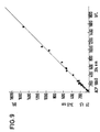
Die aufgezeichneten Abhängigkeiten der Extinktionen von der Zeit wurden nach einem der üblichen Verfahren für kinetische Messungen ausgewertet, die unbekannten Aktivitäten an Creatinkinase in der Probe wurden nach Eichung des Verfahrens mit einem Standard bestimmt. Die Übereinstimmung mit einer Vergleichsmethode, der eine der bekannten manuellen Techniken zugrunde liegt, ist sehr gut, wie Fig. 9 zeigt.The recorded dependencies of the extinctions on time were evaluated according to one of the usual methods for kinetic measurements, the unknown activities of creatine kinase in the sample were determined after calibration of the method with a standard. The agreement with a comparison method, which is based on one of the known manual techniques, is very good, as shown in FIG. 9.
IgG-Bestimmung mit dem Einsatzelement von Fig. 1 und 2.IgG determination with the insert element from FIGS. 1 and 2.
Auf Filterpapiere der Grösse 6 × 6 mm und der Dicke 0,3 mm wurden folgende Reagenzien aufgebracht und wie aus Fig. 1 eisichtlich, positioniert (in diesem Fall wurden zwei verschiedene Reagenzträgerpapiere in die gleiche Kammer gegeben):

Eine Humanserumprobe wurde 1 : 200 mit bidest. Wasser verdünnt. Von dieser verdünnten Lösung wurden 60 µl in die Probenauftragskammer 1 gegeben.A human serum sample was 1: 200 with bidist. Diluted water. 60 μl of this diluted solution were added to the sample application chamber 1.
Es wurde bei 25°C nach folgendem Programm zentrifugiert:


Die aufgezeichneten Abhängigkeiten der Extinktionen von der Zeit wurden nach einem der üblichen Verfahren zur Auswertung von kinetischen Trübungstesten ausgewertet, die unbekannten Konzentrationen an IgG in der Probe wurden nach Eichung des Verfahrens mit 3 Standards unterschiedlicher Konzentration und Erstellung einer Eichkurve bestimmt. Die Übereinstimmung mit einer Vergleichsmethode, der eine Adaptation auf dem Analysenautomaten «ABA 100» der Firma ABBOTT zugrunde liegt, ist sehr gut, wie Fig. 10 zeigt.The recorded dependencies of the extinctions on time were evaluated using one of the usual methods for evaluating kinetic turbidity tests, and the unknown concentrations of IgG in the sample were determined after calibration of the method with 3 standards of different concentrations and preparation of a calibration curve. The agreement with a comparison method, which is based on an adaptation on the automatic analyzer “
Glucosebestimmung mit dem Analysenelement gemäss Fig. 3.Determination of glucose with the analysis element according to FIG. 3.
Reagenzträgerpapiere der Grösse 6 × 6 × 0,3 mm werden wie folgt hergestellt: 10 µl der Reagenzlösungen, die ein Viertel der Substanzmengen enthalten wie die verschiedenen Papiere des Beispiels in Beispiel 1, werden auf ein Papier der angegebenen Grösse gegeben. Die Lösungen werden vollständig aufgesaugt; anschliessend wird das Lösungsmittel Wasser durch Lyophilisieren aus den Papieren entfernt.Reagent carrier papers with a size of 6 × 6 × 0.3 mm are produced as follows: 10 .mu.l of the reagent solutions, which contain a quarter of the amount of substance as the different papers of the example in Example 1, are placed on a paper of the specified size. The solutions are completely absorbed; the solvent water is then removed from the papers by lyophilization.
Die drei verschiedenen Papiere werden in der gleichen Reihenfolge wie in Beispiel 1 auf die drei Positionen des Analysenelements von Fig. 3 gelegt.The three different papers are placed in the same order as in Example 1 on the three positions of the analysis element of Fig. 3.
Die Probe wird 1 : 200 mit bidest. Wasser verdünnt. 15 µl dieser verdünnen Lösung werden in die Auftragskammer 9 gegeben. Dann wird die Lösung in der oben geschilderten Weise auf den ersten Reagenzträger 5 gebracht. Verweilzeit: 10 sec. Anschliessend wird die Lösung aus 5 nach 6 in ebenfalls bereits geschilderter Art und Weise gebracht. Verweilzeit: 10 sec. In analoger Weise wird die Lösung auf den Reagenzträger 3 (7) gebracht. Verweilzeit: 5 sec. Von dort wird die Lösung durch langsames Absenken des Stempels 16 in die Küvette 21 gebracht. In ihr wird in bekannter Weise die Extinktion bei 500 nm in Abhängigkeit von der Zeit verfolgt. Aus dem Verlauf dieser Kurve kann mit dem bekannten «Fixed-time-kinetischen» Verfahren nach Eichung mit einem Standard die Glukosekonzentration in unbekannten Proben bestimmt werden.The sample is 1: 200 with bidist. Diluted water. 15 ul of this dilute solution are placed in the
Es wurden wässrige Lösungen mit den Konzentrationen 50, 100, 150, 200, 300 und 400 mg/dl (durch Einwaage eingestellt) untersucht. Die Wiederfindung lag zwischen 98 und 102%.Aqueous solutions with the
Alkalische Phosphatase mit dem Element gemäss Fig. 3.Alkaline phosphatase with the element according to FIG. 3.
Reagenzträgerpapiere der Grösse 6 × 6 × 0,3 mm werden wie folgt hergestellt: 10 µl der Reagenzlösungen, die genau ein Viertel der Substanzmengen enthalten wie die verschiedenen Papiere des Beispiels 2, werden auf ein Papier der angegebenen Grösse gegeben. Die Lösungen werden vollständig aufgesaugt; anschliessend wird das Lösungsmittel Wasser durch Lyophilisieren aus den Papieren entfernt.Reagent carrier papers of
Die beiden Papiere werden in der gleichen Reihenfolge wie in Beispiel 2 auf die ersten beiden Positionen des Analysenelements von Fig. 3 gelegt. Auf die dritte Position wird ein Papier gelegt, das kein Reagenz enthält.The two papers are placed in the same order as in Example 2 on the first two positions of the analysis element of FIG. 3. A paper that does not contain any reagent is placed in the third position.
Die Probe wird 1 : 10 mit bidest. Wasser verdünnt. 15 µl dieser verdünnten Lösung werden in die Auftragskammer 9 gegeben. Dann wird die Lösung in der geschilderten Weise auf den ersten Reagenzträger 5 gebracht. Verweilzeit: 10 sec. Anschliessend wird die Lösung aus 5 nach 6 in ebenfalls bereits geschilderter Art und Weise gebracht. Verweilzeit: 10 sec. In analoger Weise wird die Lösung auf das Leervlies 7 gebracht. Verweilzeit: 5 sec. Von dort wird die Lösung durch langsames Absenken des Stempels 16 in die Küvette 21 gebracht. In ihr wird die Extinktion bei 410 nm in Abhängigkeit von der Zeit verfolgt. Aus dem Verlauf der aufgezeichneten Geraden kann mit bekannten kinetischen Bestimmungsverfahren nach Eichung mit einen Standard die Aktivität der alkalischen Phosphatase in unbekannten Proben bestimmt werden.The sample is 1:10 with bidist. Diluted water. 15 μl of this diluted solution are placed in the
Es wurden verschiedene Kontrollseren, die Aktivitäten zwischen 30 und 600 U/I enthielten, untersucht. Die Wiederfindung lag zwischen 90 und 110%.Various control sera containing activities between 30 and 600 U / I were examined. The recovery was between 90 and 110%.
Creatinkinasebestimmung mit dem Element gemäss Fig. 3.Determination of creatine kinase with the element according to FIG. 3.
Reagenzträgerpapiere der Grösse 6 × 6 × 0,3 mm werden wie folgt hergestellt: 10 µl der Reagenzlösungen, die genau ein Viertel der Substanzmengen enthalten wie die verschiedenen Papiere des Beispiels 4, wurden auf ein Papier der angegebenen Grösse gegeben. Die Lösungen werden vollständig aufgesaugt; anschliessend wurde das Lösungsmittel Wasser durch Lyophilisieren aus den Papieren entfernt.Reagent carrier papers of
Die beiden Papiere wurden in der gleichen Reihenfolge wie in Beispiel 4 auf die ersten beiden Positionen des Analysenelements von Fig. 3 gelegt. Auf die dritte Position wurde ein Papier der gleichen Art, das kein Reagenz enthielt, gelegt.The two papers were placed in the same order as in Example 4 on the first two positions of the analysis element of FIG. 3. A paper of the same type, which contained no reagent, was placed in the third position.
Die Probe wurde 1 : 25 mit bidest. Wasser verdünnt. 15 µl dieser verdünnten Lösung wurden in die Auftragskammer 9 gegeben. Dann wird die Lösung in der geschilderten Weise auf den ersten Reagenzträger 5 gebracht. Verweilzeit: 10 sec. Anschliessend wurde die Lösung aus 5 nach 6 in ebenfalls bereits geschilderter Art und Weise gebracht. Verweilzeit: 10 sec. In analoger Weise wurde die Lösung auf das Feld 7 bewegt. Verweilzeit: 5 sec. Von dort wird die Lösung durch langsames Absenken des Stempels 16 in die Küvette 21 gebracht. In ihr wird in bekannter Weise die Extinktion bei 340 nm in Abhängigkeit von der Zeit verfolgt. Nach einer gekrümmten Anfangsphase erhielt man einen linearen Verlauf dieser Funktion. Aus diesem Anteil wird mit Hilfe von bekannten Auswerteverfahren für kinetische Methoden nach Eichung mit einem Standard die Aktivität an Creatinkinase in einer unbekannten Probe bestimmt.The sample was 1:25 with bidist. Diluted water. 15 ul of this diluted solution were placed in the
Es wurden verschiedene Humanserumproben mit aufgereinigtem Enzym in der Weise aufgestockt, dass man Aktivitäten von 5 bis 800 U/I erhielt. Vergleichswerte wurden durch eine manuelle Messung gewonnen. Die Wiederfindungen gegenüber diesen manuellen Werten lagen zwischen 92 und 110%.Various human serum samples were purified with purified enzyme in such a way that activities of 5 to 800 U / I were obtained. Comparative values were obtained by manual measurement. The recoveries from these manual values were between 92 and 110%.
Claims (7)
Priority Applications (1)
| Application Number | Priority Date | Filing Date | Title |
|---|---|---|---|
| AT82107972T ATE14480T1 (en) | 1981-09-01 | 1982-08-30 | PROCEDURE FOR CARRYING OUT ANALYTICAL DETERMINATIONS AND MEANS SUITABLE FOR THEREOF. |
Applications Claiming Priority (2)
| Application Number | Priority Date | Filing Date | Title |
|---|---|---|---|
| DE19813134611 DE3134611A1 (en) | 1981-09-01 | 1981-09-01 | METHOD FOR CARRYING OUT ANALYTICAL PROVISIONS AND MEANS SUITABLE FOR THIS |
| DE3134611 | 1981-09-01 |
Publications (3)
| Publication Number | Publication Date |
|---|---|
| EP0073513A1 EP0073513A1 (en) | 1983-03-09 |
| EP0073513B1 EP0073513B1 (en) | 1985-07-24 |
| EP0073513B2 true EP0073513B2 (en) | 1992-02-05 |
Family
ID=6140614
Family Applications (1)
| Application Number | Title | Priority Date | Filing Date |
|---|---|---|---|
| EP82107972A Expired - Lifetime EP0073513B2 (en) | 1981-09-01 | 1982-08-30 | Method of carrying out an analytical determination, and suitable means therefor |
Country Status (8)
| Country | Link |
|---|---|
| US (2) | US4916078A (en) |
| EP (1) | EP0073513B2 (en) |
| JP (1) | JPS5847241A (en) |
| AT (1) | ATE14480T1 (en) |
| CA (1) | CA1190839A (en) |
| DE (2) | DE3134611A1 (en) |
| IL (1) | IL66576A (en) |
| ZA (1) | ZA826348B (en) |
Cited By (3)
| Publication number | Priority date | Publication date | Assignee | Title |
|---|---|---|---|---|
| US6717136B2 (en) | 2001-03-19 | 2004-04-06 | Gyros Ab | Microfludic system (EDI) |
| US6812456B2 (en) | 2001-03-19 | 2004-11-02 | Gyros Ab | Microfluidic system (EDI) |
| US7148476B2 (en) | 2001-03-19 | 2006-12-12 | Gyros Patent Ab | Microfluidic system |
Families Citing this family (59)
| Publication number | Priority date | Publication date | Assignee | Title |
|---|---|---|---|---|
| DE3425008A1 (en) * | 1984-07-06 | 1986-02-06 | Boehringer Mannheim Gmbh, 6800 Mannheim | METHOD AND DEVICE FOR CARRYING OUT ANALYTICAL PROVISIONS |
| DE3442817A1 (en) * | 1984-11-23 | 1986-05-28 | Boehringer Mannheim Gmbh, 6800 Mannheim | METHOD AND REAGENT FOR THE QUANTITATIVE DETERMINATION OF FREE THYROXIN IN PLASMA, SERUM OR WHOLE BLOOD |
| FR2581194B1 (en) * | 1985-04-29 | 1988-03-18 | Materiel Biomedical | DEVICE FOR THE ANALYSIS OF A BIOLOGICAL LIQUID. |
| US5164598A (en) * | 1985-08-05 | 1992-11-17 | Biotrack | Capillary flow device |
| US4756884A (en) * | 1985-08-05 | 1988-07-12 | Biotrack, Inc. | Capillary flow device |
| US5204525A (en) * | 1985-08-05 | 1993-04-20 | Biotrack | Capillary flow device |
| US5144139A (en) * | 1985-08-05 | 1992-09-01 | Biotrack, Inc. | Capillary flow device |
| US5140161A (en) * | 1985-08-05 | 1992-08-18 | Biotrack | Capillary flow device |
| JPS62142003A (en) * | 1985-12-13 | 1987-06-25 | Ishikawajima Harima Heavy Ind Co Ltd | Rolling installation |
| FI73529C (en) * | 1986-02-04 | 1987-10-09 | Orion Yhtymae Oy | FOERFARANDE FOER UTFOERANDE AV VAETSKEANALYS OCH ANALYSELEMENT SOM ANVAENDS I FOERFARANDET. |
| US4918025A (en) * | 1987-03-03 | 1990-04-17 | Pb Diagnostic Systems, Inc. | Self contained immunoassay element |
| AU1816888A (en) * | 1987-06-26 | 1989-01-05 | Gerrard Abdool Rayman | Device for testing fluids |
| US5173262A (en) * | 1987-07-17 | 1992-12-22 | Martin Marietta Energy Systems, Inc. | Rotor assembly and method for automatically processing liquids |
| US5242803A (en) * | 1987-07-17 | 1993-09-07 | Martin Marietta Energy Systems, Inc. | Rotor assembly and assay method |
| US5077017A (en) * | 1987-11-05 | 1991-12-31 | Biotrack, Inc. | Integrated serial dilution and mixing cartridge |
| GB8728639D0 (en) * | 1987-12-08 | 1988-01-13 | Scient Generics Ltd | Device for analytical determinations |
| US4999304A (en) * | 1987-12-28 | 1991-03-12 | Miles Inc. | Dynamic braking centrifuge |
| JPH0266431A (en) * | 1988-08-31 | 1990-03-06 | Tdk Corp | Electrochemical optical characteristic measuring cell |
| US5230866A (en) * | 1991-03-01 | 1993-07-27 | Biotrack, Inc. | Capillary stop-flow junction having improved stability against accidental fluid flow |
| US5258314A (en) * | 1991-03-18 | 1993-11-02 | Paradigm Biotechnologies Partnership | Microprocessor-based biomedical monitoring apparatus and method |
| US5607863A (en) * | 1991-05-29 | 1997-03-04 | Smithkline Diagnostics, Inc. | Barrier-controlled assay device |
| US6168956B1 (en) | 1991-05-29 | 2001-01-02 | Beckman Coulter, Inc. | Multiple component chromatographic assay device |
| US5468648A (en) * | 1991-05-29 | 1995-11-21 | Smithkline Diagnostics, Inc. | Interrupted-flow assay device |
| US5998220A (en) | 1991-05-29 | 1999-12-07 | Beckman Coulter, Inc. | Opposable-element assay devices, kits, and methods employing them |
| US5877028A (en) | 1991-05-29 | 1999-03-02 | Smithkline Diagnostics, Inc. | Immunochromatographic assay device |
| US5869345A (en) * | 1991-05-29 | 1999-02-09 | Smithkline Diagnostics, Inc. | Opposable-element assay device employing conductive barrier |
| US5304348A (en) * | 1992-02-11 | 1994-04-19 | Abaxis, Inc. | Reagent container for analytical rotor |
| WO1993019827A1 (en) * | 1992-04-02 | 1993-10-14 | Abaxis, Inc. | Analytical rotor with dye mixing chamber |
| DE4212280A1 (en) * | 1992-04-11 | 1993-10-14 | Boehringer Mannheim Gmbh | Asymmetrically porous membranes |
| US5783446A (en) * | 1996-03-04 | 1998-07-21 | Biocircuits Corporation | Particle assay using fluid velocity gradients |
| US5879951A (en) | 1997-01-29 | 1999-03-09 | Smithkline Diagnostics, Inc. | Opposable-element assay device employing unidirectional flow |
| US5939252A (en) | 1997-05-09 | 1999-08-17 | Lennon; Donald J. | Detachable-element assay device |
| US6013513A (en) * | 1997-10-30 | 2000-01-11 | Motorola, Inc. | Molecular detection apparatus |
| EP1032840A1 (en) * | 1997-11-19 | 2000-09-06 | ABION Beteiligungs- und Verwaltungsgesellschaft mbH | Multi-manifold device for carrying out chemical, biological and/or biochemical analytical methods |
| US7014815B1 (en) | 1998-10-30 | 2006-03-21 | Burstein Technologies, Inc. | Trackable optical discs with concurrently readable nonoperational features |
| US6531095B2 (en) | 1999-02-11 | 2003-03-11 | Careside, Inc. | Cartridge-based analytical instrument with optical detector |
| US6391264B2 (en) | 1999-02-11 | 2002-05-21 | Careside, Inc. | Cartridge-based analytical instrument with rotor balance and cartridge lock/eject system |
| AU3359100A (en) * | 1999-02-11 | 2000-08-29 | Careside, Inc. | Cartridge-based analytical instrument |
| US6348176B1 (en) | 1999-02-11 | 2002-02-19 | Careside, Inc. | Cartridge-based analytical instrument using centrifugal force/pressure for metering/transport of fluids |
| DE19932958C2 (en) | 1999-07-14 | 2003-08-07 | Walter Schubert | Device for binding molecules, groups of molecules, parts of molecules and / or cells |
| US6593143B1 (en) * | 2000-02-29 | 2003-07-15 | Agilent Technologies, Inc. | Centrifuge system with contactless regulation of chemical-sample temperature using eddy currents |
| US6571651B1 (en) * | 2000-03-27 | 2003-06-03 | Lifescan, Inc. | Method of preventing short sampling of a capillary or wicking fill device |
| EP1410044A2 (en) * | 2000-11-08 | 2004-04-21 | Burstein Technologies, Inc. | Interactive system for analyzing biological samples and processing related information and the use thereof |
| WO2002046747A1 (en) * | 2000-12-06 | 2002-06-13 | Kabushiki Kaisya Advance | Facilitated body fluid inspection unit |
| US6760298B2 (en) * | 2000-12-08 | 2004-07-06 | Nagaoka & Co., Ltd. | Multiple data layer optical discs for detecting analytes |
| WO2002046762A2 (en) * | 2000-12-08 | 2002-06-13 | Burstein Technologies, Inc. | Optical disc assemblies for performing assays |
| US7091034B2 (en) * | 2000-12-15 | 2006-08-15 | Burstein Technologies, Inc. | Detection system for disk-based laboratory and improved optical bio-disc including same |
| EP1384076B1 (en) | 2001-03-19 | 2012-07-25 | Gyros Patent Ab | Characterization of reaction variables |
| US20020171838A1 (en) * | 2001-05-16 | 2002-11-21 | Pal Andrew Attila | Variable sampling control for rendering pixelization of analysis results in a bio-disc assembly and apparatus relating thereto |
| US20040241381A1 (en) * | 2002-01-31 | 2004-12-02 | Chen Yihfar | Microfluidic structures with circumferential grooves for bonding adhesives and related optical analysis discs |
| AU2008269201B2 (en) | 2007-06-21 | 2011-08-18 | Gen-Probe Incorporated | Instrument and receptacles for use in performing processes |
| WO2009099512A2 (en) * | 2008-02-04 | 2009-08-13 | Micropoint Biosciences, Inc. | Centrifugal fluid analyzer rotor |
| EP2795295B1 (en) | 2011-12-12 | 2017-10-11 | Step Ahead Innovations, Inc. | Water-quality monitoring system |
| US9784686B2 (en) | 2013-06-19 | 2017-10-10 | Step Ahead Innovations, Inc. | Aquatic environment water parameter testing systems and methods |
| US9308508B2 (en) | 2013-07-22 | 2016-04-12 | Kianoosh Peyvan | Sequential delivery device and method |
| EP2942104A1 (en) | 2014-05-08 | 2015-11-11 | Radisens Diagnostics Ltd. | Sample applicator for point of care device |
| WO2017184629A1 (en) | 2016-04-22 | 2017-10-26 | Becton, Dickinson And Company | Multiplex polymeric dye devices and methods for using the same |
| US11320437B2 (en) | 2017-02-08 | 2022-05-03 | Becton, Dickinson And Company | Dried dye reagent devices and methods for making and using the same |
| JP2023515142A (en) | 2020-02-25 | 2023-04-12 | ヘリックスバインド・インコーポレイテッド | Reagent carrier for fluidic systems |
Family Cites Families (30)
| Publication number | Priority date | Publication date | Assignee | Title |
|---|---|---|---|---|
| US3036894A (en) * | 1958-10-22 | 1962-05-29 | Jasper A Forestiere | Method of using testing containers |
| DE1773584A1 (en) * | 1967-06-13 | 1973-01-04 | Xerox Corp | REACTION VESSEL |
| US3532470A (en) * | 1968-01-22 | 1970-10-06 | Beckman Instruments Inc | Sample holder with centrifugation means |
| US3540857A (en) * | 1968-01-22 | 1970-11-17 | Beckman Instruments Inc | Sample capsule and filtering mechanism |
| US3733179A (en) * | 1968-08-29 | 1973-05-15 | Minnesota Mining & Mfg | Method and apparatus for the quantitative determination of blood chemicals in blood derivatives |
| DD101014A1 (en) * | 1973-01-04 | 1973-10-12 | ||
| US3795451A (en) * | 1973-04-24 | 1974-03-05 | Atomic Energy Commission | Rotor for fast analyzer of rotary cuvette type |
| US4007010A (en) * | 1974-07-03 | 1977-02-08 | Woodbridge Iii Richard G | Blister plane apparatus for testing samples of fluid |
| GB1522965A (en) * | 1974-08-19 | 1978-08-31 | Damon Corp | Method and apparatus of chemical photometric spot test analysis |
| CH587486A5 (en) * | 1974-11-29 | 1977-05-13 | Hoffmann La Roche | |
| US3972595A (en) * | 1975-01-27 | 1976-08-03 | International Business Machines Corporation | Ferrofluid display device |
| US4042335A (en) * | 1975-07-23 | 1977-08-16 | Eastman Kodak Company | Integral element for analysis of liquids |
| DE2553613C3 (en) * | 1975-11-28 | 1978-11-23 | Compur-Electronic Gmbh, 8000 Muenchen | Process for the preparation of measuring liquids |
| FR2341865A1 (en) * | 1976-02-19 | 1977-09-16 | Api Labor | SUPPORT FOR THE ASSESSMENT OF ENZYMATIC ACTIVITIES AND METHOD OF ASSESSMENT USING THIS SUPPORT |
| US4065263A (en) * | 1976-04-02 | 1977-12-27 | Woodbridge Iii Richard G | Analytical test strip apparatus |
| IT1097442B (en) * | 1977-08-18 | 1985-08-31 | Guigan Jean | CONDITIONING DEVICE OF A LIQUID SAMPLE IN PREPARATION OF ITS ANALYSIS |
| FR2409514A1 (en) * | 1977-11-17 | 1979-06-15 | Bretaudiere Jean Pierre | DEVELOPMENT OF CENTRIFUGATION ANALYSIS EQUIPMENT |
| US4260392A (en) * | 1978-07-07 | 1981-04-07 | Technicon Instruments Corporation | Method and apparatus for obtaining an aliquot of a liquid in a gel medium |
| US4233029A (en) * | 1978-10-25 | 1980-11-11 | Eastman Kodak Company | Liquid transport device and method |
| CA1129498A (en) * | 1978-10-25 | 1982-08-10 | Richard L. Columbus | Structural configuration and method for transport of a liquid drop through an ingress aperture |
| US4237234A (en) * | 1978-10-30 | 1980-12-02 | Meunier Henry E | Device for use in the study of biochemical or enzymatic reactions produced by living organisms |
| DE2915248C3 (en) * | 1979-04-14 | 1982-01-14 | Gise, Frhr. von, Hardo, Dr.med., 7400 Tübingen | Device for automatic selective and exact treatment of specimens |
| IN154925B (en) * | 1979-10-26 | 1984-12-22 | Guigan Jean | |
| CA1152353A (en) * | 1980-05-05 | 1983-08-23 | Georges Revillet | Multicuvette rotor for analyser |
| US4305722A (en) * | 1980-06-13 | 1981-12-15 | Coulter Electronics, Inc. | Wetting cycle for spun blood smears |
| US4387164A (en) * | 1980-11-05 | 1983-06-07 | Fmc Corporation | Method and apparatus for chemical analysis using reactive reagents dispersed in soluble film |
| DE3044372A1 (en) * | 1980-11-25 | 1982-07-08 | Boehringer Mannheim Gmbh, 6800 Mannheim | ROTOR UNIT WITH INSERT ELEMENTS FOR A CENTRIFUGAL ANALYZER |
| DE3044385A1 (en) * | 1980-11-25 | 1982-06-24 | Boehringer Mannheim Gmbh, 6800 Mannheim | METHOD FOR CARRYING OUT ANALYTICAL PROVISIONS AND ROTOR INSERT ELEMENT SUITABLE FOR THIS |
| US4426451A (en) * | 1981-01-28 | 1984-01-17 | Eastman Kodak Company | Multi-zoned reaction vessel having pressure-actuatable control means between zones |
| US4390499A (en) * | 1981-08-13 | 1983-06-28 | International Business Machines Corporation | Chemical analysis system including a test package and rotor combination |
-
1981
- 1981-09-01 DE DE19813134611 patent/DE3134611A1/en not_active Ceased
-
1982
- 1982-08-19 IL IL66576A patent/IL66576A/en unknown
- 1982-08-30 JP JP57149356A patent/JPS5847241A/en active Granted
- 1982-08-30 DE DE8282107972T patent/DE3264913D1/en not_active Expired
- 1982-08-30 AT AT82107972T patent/ATE14480T1/en active
- 1982-08-30 CA CA000410449A patent/CA1190839A/en not_active Expired
- 1982-08-30 EP EP82107972A patent/EP0073513B2/en not_active Expired - Lifetime
- 1982-08-31 ZA ZA826348A patent/ZA826348B/en unknown
-
1987
- 1987-09-03 US US07/093,136 patent/US4916078A/en not_active Expired - Fee Related
-
1988
- 1988-01-25 US US07/147,610 patent/US4898832A/en not_active Expired - Fee Related
Cited By (3)
| Publication number | Priority date | Publication date | Assignee | Title |
|---|---|---|---|---|
| US6717136B2 (en) | 2001-03-19 | 2004-04-06 | Gyros Ab | Microfludic system (EDI) |
| US6812456B2 (en) | 2001-03-19 | 2004-11-02 | Gyros Ab | Microfluidic system (EDI) |
| US7148476B2 (en) | 2001-03-19 | 2006-12-12 | Gyros Patent Ab | Microfluidic system |
Also Published As
| Publication number | Publication date |
|---|---|
| EP0073513B1 (en) | 1985-07-24 |
| IL66576A (en) | 1987-12-20 |
| CA1190839A (en) | 1985-07-23 |
| JPH0133776B2 (en) | 1989-07-14 |
| EP0073513A1 (en) | 1983-03-09 |
| IL66576A0 (en) | 1982-12-31 |
| DE3134611A1 (en) | 1983-03-10 |
| US4898832A (en) | 1990-02-06 |
| JPS5847241A (en) | 1983-03-18 |
| US4916078A (en) | 1990-04-10 |
| ZA826348B (en) | 1983-07-27 |
| DE3264913D1 (en) | 1985-08-29 |
| ATE14480T1 (en) | 1985-08-15 |
Similar Documents
| Publication | Publication Date | Title |
|---|---|---|
| EP0073513B2 (en) | Method of carrying out an analytical determination, and suitable means therefor | |
| EP0052769B1 (en) | Method for analytical assays and rotor element for carrying out the method | |
| DE69906986T2 (en) | ANALYTICAL TEST APPARATUS AND METHOD | |
| EP1445020B1 (en) | Analytical test element and blood test method | |
| DE69719399T2 (en) | Device and method for analyzing a sample | |
| EP2069787B1 (en) | Rotatable test element | |
| DE60121404T2 (en) | BIOSENSOR | |
| DE602004013339T2 (en) | MIXING IN MICROFLUID DEVICES | |
| DE602005005485T2 (en) | ASSAY DEVICE AND METHOD WITH CONTROLLED RIVER | |
| DE19781288B4 (en) | Opaque reaction matrix for analysis of whole blood | |
| EP1032840A1 (en) | Multi-manifold device for carrying out chemical, biological and/or biochemical analytical methods | |
| EP0634215A1 (en) | Device for simultaneous determination of analytes | |
| EP0167171A2 (en) | Method and device for performing analytical determinations | |
| EP0290921A2 (en) | Test-piece for the analysis of a liquid sample and method for its preparation | |
| EP1522343B1 (en) | Analytical testelement including a hydrophilic network for forming a capillary channel, its use and method for determining an analyte in a liquid. | |
| CH627280A5 (en) | ||
| DE3235658C2 (en) | ||
| EP0797097B1 (en) | Particle immuno assay with compact matrix | |
| EP0457123B1 (en) | Test support for the analytical determination of a component in a sample fluid | |
| EP0281112A1 (en) | Device for performing a heterogenous reaction | |
| DE3703189C2 (en) | ||
| DE3903114A1 (en) | METHOD FOR DETERMINING AN ENZYME FROM AN ISOZYME MIXTURE, AND TEST CARRIER SUITABLE FOR THIS, AND USE THEREOF | |
| DE2736527A1 (en) | METHOD AND DEVICE FOR DETECTION OF A SPECIFIC BINDING PROTEIN OR A SUBSTANCE THAT CAN BE BINDED WITH IT | |
| DE3716891A1 (en) | TEST KIT FOR DETERMINING ANALYTIC IN THE CHAIR | |
| DE19502375C2 (en) | Narcotics detection system |
Legal Events
| Date | Code | Title | Description |
|---|---|---|---|
| PUAI | Public reference made under article 153(3) epc to a published international application that has entered the european phase |
Free format text: ORIGINAL CODE: 0009012 |
|
| 17P | Request for examination filed |
Effective date: 19821012 |
|
| AK | Designated contracting states |
Designated state(s): AT BE CH DE FR GB IT LI LU NL SE |
|
| ITF | It: translation for a ep patent filed |
Owner name: ING. C. GREGORJ S.P.A. |
|
| GRAA | (expected) grant |
Free format text: ORIGINAL CODE: 0009210 |
|
| AK | Designated contracting states |
Designated state(s): AT BE CH DE FR GB IT LI LU NL SE |
|
| REF | Corresponds to: |
Ref document number: 14480 Country of ref document: AT Date of ref document: 19850815 Kind code of ref document: T |
|
| REF | Corresponds to: |
Ref document number: 3264913 Country of ref document: DE Date of ref document: 19850829 |
|
| PG25 | Lapsed in a contracting state [announced via postgrant information from national office to epo] |
Ref country code: LU Free format text: LAPSE BECAUSE OF NON-PAYMENT OF DUE FEES Effective date: 19850831 |
|
| ET | Fr: translation filed | ||
| PLBI | Opposition filed |
Free format text: ORIGINAL CODE: 0009260 |
|
| 26 | Opposition filed |
Opponent name: F. HOFFMANN-LA ROCHE & CO. AKTIENGESELLSCHAFT Effective date: 19860423 |
|
| NLR1 | Nl: opposition has been filed with the epo |
Opponent name: F. HOFFMANN-LA ROCHE & CO. AKTIENGESELLSCHAFT |
|
| PGFP | Annual fee paid to national office [announced via postgrant information from national office to epo] |
Ref country code: NL Payment date: 19860831 Year of fee payment: 5 |
|
| PG25 | Lapsed in a contracting state [announced via postgrant information from national office to epo] |
Ref country code: SE Effective date: 19870831 |
|
| BERE | Be: lapsed |
Owner name: BOEHRINGER MANNHEIM G.M.B.H. Effective date: 19870831 |
|
| PG25 | Lapsed in a contracting state [announced via postgrant information from national office to epo] |
Ref country code: NL Effective date: 19880301 |
|
| NLV4 | Nl: lapsed or anulled due to non-payment of the annual fee | ||
| PG25 | Lapsed in a contracting state [announced via postgrant information from national office to epo] |
Ref country code: BE Effective date: 19890831 |
|
| ITTA | It: last paid annual fee | ||
| PUAH | Patent maintained in amended form |
Free format text: ORIGINAL CODE: 0009272 |
|
| STAA | Information on the status of an ep patent application or granted ep patent |
Free format text: STATUS: PATENT MAINTAINED AS AMENDED |
|
| 27A | Patent maintained in amended form |
Effective date: 19920205 |
|
| AK | Designated contracting states |
Kind code of ref document: B2 Designated state(s): AT BE CH DE FR GB IT LI LU NL SE |
|
| REG | Reference to a national code |
Ref country code: CH Ref legal event code: AEN |
|
| ITF | It: translation for a ep patent filed |
Owner name: ING. C. GREGORJ S.P.A. |
|
| ET3 | Fr: translation filed ** decision concerning opposition | ||
| EUG | Se: european patent has lapsed |
Ref document number: 82107972.0 Effective date: 19880711 |
|
| PGFP | Annual fee paid to national office [announced via postgrant information from national office to epo] |
Ref country code: FR Payment date: 19950809 Year of fee payment: 14 |
|
| PGFP | Annual fee paid to national office [announced via postgrant information from national office to epo] |
Ref country code: AT Payment date: 19950811 Year of fee payment: 14 |
|
| PGFP | Annual fee paid to national office [announced via postgrant information from national office to epo] |
Ref country code: GB Payment date: 19950821 Year of fee payment: 14 |
|
| PGFP | Annual fee paid to national office [announced via postgrant information from national office to epo] |
Ref country code: CH Payment date: 19950828 Year of fee payment: 14 |
|
| PGFP | Annual fee paid to national office [announced via postgrant information from national office to epo] |
Ref country code: DE Payment date: 19950829 Year of fee payment: 14 |
|
| PG25 | Lapsed in a contracting state [announced via postgrant information from national office to epo] |
Ref country code: GB Effective date: 19960830 Ref country code: AT Effective date: 19960830 |
|
| PG25 | Lapsed in a contracting state [announced via postgrant information from national office to epo] |
Ref country code: LI Effective date: 19960831 Ref country code: CH Effective date: 19960831 |
|
| APAC | Appeal dossier modified |
Free format text: ORIGINAL CODE: EPIDOS NOAPO |
|
| APAC | Appeal dossier modified |
Free format text: ORIGINAL CODE: EPIDOS NOAPO |
|
| REG | Reference to a national code |
Ref country code: CH Ref legal event code: PL |
|
| GBPC | Gb: european patent ceased through non-payment of renewal fee |
Effective date: 19960830 |
|
| PG25 | Lapsed in a contracting state [announced via postgrant information from national office to epo] |
Ref country code: FR Effective date: 19970430 |
|
| PG25 | Lapsed in a contracting state [announced via postgrant information from national office to epo] |
Ref country code: DE Effective date: 19970501 |
|
| REG | Reference to a national code |
Ref country code: FR Ref legal event code: ST |
|
| APAH | Appeal reference modified |
Free format text: ORIGINAL CODE: EPIDOSCREFNO |