EP0071538A1 - Apparatus for transferring animal reproduction elements, embryos or the like - Google Patents
Apparatus for transferring animal reproduction elements, embryos or the like Download PDFInfo
- Publication number
- EP0071538A1 EP0071538A1 EP82401420A EP82401420A EP0071538A1 EP 0071538 A1 EP0071538 A1 EP 0071538A1 EP 82401420 A EP82401420 A EP 82401420A EP 82401420 A EP82401420 A EP 82401420A EP 0071538 A1 EP0071538 A1 EP 0071538A1
- Authority
- EP
- European Patent Office
- Prior art keywords
- tube
- reservoir tube
- main body
- rigid
- sheath
- Prior art date
- Legal status (The legal status is an assumption and is not a legal conclusion. Google has not performed a legal analysis and makes no representation as to the accuracy of the status listed.)
- Granted
Links
Images


Classifications
-
- A—HUMAN NECESSITIES
- A61—MEDICAL OR VETERINARY SCIENCE; HYGIENE
- A61D—VETERINARY INSTRUMENTS, IMPLEMENTS, TOOLS, OR METHODS
- A61D19/00—Instruments or methods for reproduction or fertilisation
- A61D19/04—Instruments or methods for reproduction or fertilisation for embryo transplantation
-
- A—HUMAN NECESSITIES
- A61—MEDICAL OR VETERINARY SCIENCE; HYGIENE
- A61D—VETERINARY INSTRUMENTS, IMPLEMENTS, TOOLS, OR METHODS
- A61D19/00—Instruments or methods for reproduction or fertilisation
- A61D19/02—Instruments or methods for reproduction or fertilisation for artificial insemination
- A61D19/027—Devices for injecting semen into animals, e.g. syringes, guns, probes
Definitions
- the present invention relates to devices for transferring elements of animal reproduction, such as embryos (from a donor reproductive female and to be placed in a carrier female) or animal semen (taken from a male for the purpose of 'artificial insemination). It relates more particularly to devices of the purely mechanical ejection type, comprising a hollow and rigid main body, of generally cylindrical shape, at one end of which a flexible tube can be fixed, to serve as a reservoir for the reproduction elements, while it internally receives, at its other end, a piston rod with which is associated a sliding piston, the free end of the reservoir tube comprising, moreover, an ejection nozzle with axial passage, the body being able, moreover, to be advantageously surrounded externally, over at least a large part of its length, by a protective sheath fixed on it, which is changed at each operation, which avoids sterilization of the device.
- the reservoir tube is housed on the largest part of its length, inside the rigid body, and the piston is directly actuated by the end of the rod, the length of which is roughly equal to that of the body (as well as that of the protective sheath , when provided, in which case the endpiece is, moreover, interposed between the end of the reservoir tube and that of the sheath, both of which protrude slightly from the body).
- the entire apparatus is rigid over its entire length and the rod and piston assembly is used at least to push the reproductive elements into the womb of the breeding female, in the case of semen , in that of the carrier female, in the case of an embryo.
- This same rod and piston assembly may, moreover, have already been used, in addition, for the aspiration of the semen in a particular embodiment of the first case.
- it is a reservoir tube previously filled with semen, or a suspension containing the embryo, and in general stored under refrigeration, after removal from the male or the breeding female, which is fixed on the body of the device, a tampon which seals the end of the tube then serving as a piston during ejection.
- the free end of this device should, in principle, be inserted beyond the vagina and cervix, as far as possible inside the uterus of the animal, to ensure a deep deposit of the semen or embryo and therefore, facilitate reproduction or implantation.
- the uterine lining is extremely fragile (particularly in the case of an embryo transfer, which should normally take place outside the estrus period), so that these known devices risk, made of their rigid end, to cause a lesion of this mucosa with all the consequences that this entails.
- known devices for example, the aforementioned patent 80 04 607 in fact only allow the placement of the embryo in the carrier female, the collection on the female reproductive using a completely separate device and operating as a whole other type, since by circulation of fluid (such as that described in the applicants' French patent 80 04 606).
- the delivery device must receive a reservoir tube already filled with the embryo suspension.
- the main object of the present invention is to minimize the risk of damage to the uterine lining and, for this purpose, it relates to a transfer device of the aforementioned type, characterized in that the rigid main body is surrounded by a second non-flexible body, inside which the main body can slide and which has approximately the same length as this, while the piston rod comprises a front section which is flexible and has a length at least equal to that of the tube -tank.
- the external body when the external body is placed so as to normally surround the main body, it is possible to fix the filled reservoir tube at the front end of this main body, then make the same main body move back with respect to the external body, until the reservoir tube has almost completely penetrated inside the external body, which makes the front end of the device rigid enough to allow it to easily cross the vagina and especially the cervix of the female carrier , as a result of which the main body can be pushed forward, so as to gradually introduce the reservoir tube into the uterine lumen, and this easily and without damage to the mucous membrane thereof, despite the meanders that present this light, since the reservoir tube can perfectly adapt to the latter by bending thanks to its flexibility, the transfer being completed by a push of the piston rod (which had previously r offset with the main body) which mechanically causes the ejection of the contents of the reservoir tube, the front element of the piston rod also adapting, due to its flexibility, to the curvature of the tube imparted by the meanders of the uterus.
- the apparatus can, moreover, comprise a rigid fixing sheath which can surround the reservoir tube and which has, at one end, means for retaining the endpiece fixed to the front end of the tube -reservoir, and at the other end, support means on the front end of the outer body, this sheath favoring the maintenance of the reservoir tube, which is flexible, while it is fixed at the end of the body main, for example by interlocking, while simultaneously ensuring perfect asepsis of the operation.
- a rigid fixing sheath which can surround the reservoir tube and which has, at one end, means for retaining the endpiece fixed to the front end of the tube -reservoir, and at the other end, support means on the front end of the outer body, this sheath favoring the maintenance of the reservoir tube, which is flexible, while it is fixed at the end of the body main, for example by interlocking, while simultaneously ensuring perfect asepsis of the operation.
- this can very advantageously be arranged around the external body, so as to protrude slightly at the front thereof, presenting at its front end a rounded inner hem, while it is, moreover, fixed on the same outer body at its opposite end, which allows, when the main body recedes, to fully retract the reservoir tube inside this sheath , the hem of the latter avoiding any lesion of the mucosa during introduction into the uterus.
- the end piece fixed to the end of the reservoir tube has, at the front, a rigid spherical head, which can pass elastically through the hem of the sheath, while its central passage opens out.
- the spherical head due to its shape, progresses easily and without damage in the uterine lumen.
- the object of the invention is also to enable the suspension, containing the embryo (s) containing the embryo (s), to be carried out by means of the same device, by aspiration, in an intermediate storage container, without the need to use other specialized devices for this purpose.
- the apparatus according to the invention is, furthermore, characterized in that the flexible front section of the piston rod carries, at its front end, the ejection piston and is separated from the rear section of the rod which is rigid.
- the subassembly of the device constituted by the reservoir tube and the flexible front section of rod, can be separated from the rest of the device to operate like a syringe for aspirating, in a storage container, the suspension containing the embryo, this sub-assembly then being reattached to the rest of the device to allow introduction and ejection in the manner already indicated.
- the apparatus may also comprise a rigid guide sleeve which can surround the reservoir tube and which has, at one end, means for retaining the end of the reservoir tube opposite to that which must receive the tip, this sheath favoring the maintenance of the reservoir tube during the aspiration of the suspension, which avoids, during handling, any twisting which could block the aspiration of the embryo, while ensuring the asepsis of this operation.
- a rigid guide sleeve which can surround the reservoir tube and which has, at one end, means for retaining the end of the reservoir tube opposite to that which must receive the tip, this sheath favoring the maintenance of the reservoir tube during the aspiration of the suspension, which avoids, during handling, any twisting which could block the aspiration of the embryo, while ensuring the asepsis of this operation.
- the apparatus represented by the figures essentially consists of a main body 1 (Fig. 1), an outer body 2 (Fig. 2), a rigid element of piston rod 3 (Fig. 3), a reservoir tube 4 (Fig. 4), a flexible front section of piston rod 5 (Fig. 5), a nozzle 6 for the reservoir tube (Fig. 6), and an ejection piston 7 (Fig. 7), these various elements, shown separately in Figs. 1 to 7, being, moreover, supplemented by a suction and fixing tube 8 (Fig. 8 to 12), a protective sheath 9 (Fig. 11 to 13), and finally a clamping screw 10 (Fig . 11 to 13).
- the outer body 1 is a body of stainless steel, hollow and rigid, of generally cylindrical shape, and more particularly constituted by a tube 1a extending over its entire length and on the rear end 1b of which is force fitted, a sheath lc, also made of stainless steel, which has a frustoconical interlocking surface ld at the front, converging towards the front, and at the rear, an operating head, of annular shape, the which has a radial tapping If also passing through the tube la, so as to open into the lumen of the latter, the central portion of this sheath lc finally connecting it, radially and outwards to the frustoconical bearing ld by a shoulder 1g.
- the main body 2 (FIG. 2) is also formed by a stainless steel body, hollow and rigid, and also of generally cylindrical shape, but more particularly constituted by a tube 2a whose outside diameter corresponds to the inside diameter of the tube la, and at the rear end 2b of which is fixed an operating head 2c, of annular shape, and also made of stainless steel, while at its front end, this same tube has three grooves distinct annulars separated by two frustoconical interlocking surfaces 2d and 2e, which converge towards the front and which are connected to the grooves behind them, by shoulders 2f.
- the tube 2a is relatively longer than the tube la of the outer body, so that when the main body 2 is introduced into this outer body 1, as shown in FIG.
- the rear piston rod element 3 (FIG. 3) is also constituted by a hollow and rigid tube 3a, made of stainless steel, on the rear end 3b of which an actuator head of annular shape is fixed, and also in stainless steel, 3c, while at its front end 3d, this tube has, over a certain length, a wider bore 3e.
- the outer diameter of this tube 3a corresponds to the inner diameter of the tube 2a of the main body, and its length is somewhat shorter than that of the outer body 1, so that when this rear piston rod element 3 is introduced into the inside the main body 2 until, as also shown in FIG. 11, the two gripping heads 2c and 3c, forming abutment means, come to bear one on the other, the front end of the tube 3 remains slightly set back relative to that of the body 1.
- the reservoir tube 4 (Fig. 4) is a perfectly cylindrical tube over its entire length, and made of a flexible plastic material, such as flexible polyvinyl chloride. Its outer diameter is substantially equal to that of the main body 2 and its inner diameter substantially equal to the diameter of the grooves 2g, located at the front end 2h of this tube, so that, as shown in FIG. 11, the rear end 4a of the reservoir tube can come to fit elastically over the two frustoconical bearing surfaces 2d and 2e of the main body, until it comes into abutment against the rear shoulder of the rear groove 2g.
- the length of this tube is provided so as to correspond, on the one hand, to a normal volume of the suspension containing the embryo (s) that this tube must contain, and, on the other hand, to the average length of the genital tract of the female.
- the flexible front section of piston rod 5 (FIG. 5) is constituted by a solid rod or rod, also made of flexible plastic, such as flexible polyvinyl chloride.
- the diameter of this rod is quite clearly less than the inside diameter of the reservoir tube 4, so that, when this rod is disposed inside this tube, as shown in FIG. 11, there remains a substantial radial clearance between them, this same diameter of the rod corresponding, moreover, very precisely to the diameter of the bore 3e of the rear piston rod element 3, which allows it to be able to come fully engage it, as shown in Fig. 11.
- the length of this rod is approximately of the same order of magnitude as that of the reservoir tube 4.
- the end piece 6 (Fig. 6) is a piece of stainless steel, of generally relatively short cylindrical shape and which comprises, at its rear end, a frustoconical interlocking surface 6a, converging towards the rear and separated from the current part cylindrical by a groove 6b, while at its front end is welded a spherical head also made of stainless steel 6c, of slightly larger diameter, a central passage 6d finally extending over the greater part of this endpiece to open axially at the rear, while it opens on the side and at the rear of the spherical head 6c, using a 6th elbow.
- the diameter of the current part of the end piece corresponds to that of the reservoir tube 4, so that, as still shown in FIG. 11, the front end 4b of this tube, can come fit elastically, over the frustoconical surface 6a, and until it abuts against the front shoulder of the groove 6b.
- the piston rod 7 (FIG. 7) is a plastic part, of generally relatively short cylindrical shape, comprising at the front a frustoconical head 7a, while at the rear there is arranged axially a blind bore 7b, diameter corresponding to that of the rod 5, so that the front end 5a of the latter can come to fit there, as shown in FIG. 8.
- the protective sheath 9 is a thin cylindrical sheath, made of a semi-rigid plastic material, such as semi-rigid polyvinyl chloride. Its diameter corresponds substantially to that of the current part lc of the external body 1, so that, as still shown in FIG. 11, this sheath can be fixed elastically, by its rear end 9a, over the frustoconical surface ld of this body, and until it comes into abutment against the head le.
- the length of this sheath is such that, in this latter position, its front end 9b comes substantially at the level of the groove 2g rear of the main body 2, and consequently of the rear edge of the reservoir tube 4 when the latter has come 'fitting over this body 2.
- This same front end 9b of the sheath has a rounded hem 9c, rounded folded inwards, which comes into contact with said rear edge of the tube 4.
- the suction and fixing sleeve 8 (Fig. 8) consists of a relatively rigid plastic tube, the length of which is roughly equal to that of the reservoir tube 4, and the current diameter of which is relatively greater than that of this same tube. At one end 8a, this sheath has a cylindrical constriction, of diameter still greater than that of the tube 4 but corresponding, on the other hand, to that of the hem 9c of the sheath, so that these two parts can be supported Moon against the other, retort shown in Fig. 11.
- this sheath has another constriction, of frustoconical shape, the end of which provided with a hem has a diameter corresponding substantially to the diameter of the reservoir tube 4, so as to be able to act as a support either to the latter itself (Fig. 4), or to the spherical head 6c of its tip (Fig. 10 and 11).
- the screw 10 As for the screw 10 (Fig. 11), it has a threaded portion 10a which can be screwed into the internal thread if of the outer body 1, and an operating head 10b.
- the operator positions, using sterilized forceps, the nozzle 6 terminated by its spherical head 6c, at the front end 4b of the tube 4, the fixing being done by elastic fitting of the tube 4 on the frustoconical surface 6a (Fig. 9).
- the operator introduces the sub-assembly into the same rigid sheath 8, but this time by its opposite end, of so that the end piece 6 comes to bear, by its spherical head 6a, against the hem of the frustoconical constriction 8b of this sheath (Fig. 10).
- the operator then brings the flexible sub-assembly, held by the rigid sheath, facing the rest of the apparatus consisting of the sheath 9, the external body 1, the main body 2 and the piston rod 3, already introduced respectively. one inside the other, and in support, by their operating heads, as shown in FIG. 11, the screw 10, which is fixed in the head of the outer body, also passing through a hole 2i of the main body to come to bear at its end on the piston rod 3, which ensures the assembly of the assembly.
- the sheath 8 which came to bear on the hem 9c of the sheath 9
- the operator guides the rear end 4a of the reservoir tube on the frustoconical surfaces 2d and 2e of the main body, up to ensure elastic fitting of this tube on this body (Fig. 11).
- the operator releases the screw 10 and very gently pushes, using its head 2c, the external body 2 which carries, on its front end, the reservoir tube 4, in a forward movement, and this as much as necessary so that the nozzle 6 and its lateral ejection orifice 6e reach the optimal ejection position.
- the flexibility of the flexible sub-assembly 4-5 makes it possible to follow the meanders and the curvature of the uterine horn.
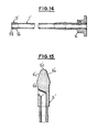
- the body 1 and the sheath 9 of the above-described embodiment are replaced by a single part constituted by a modification 1a of the external body (Fig. 14).
- This body differs by the presence of a small metal sleeve 9 'which is forcibly engaged on the free end of the tube (opposite its head).
- This metal sleeve extends over a length which is of the order of magnitude of its outside diameter and successively presents, in the direction of the free end, a divergent frustoconical surface with very slight slope 9'a, then a clearly rounded fillet shorter 9'b which is flush with the edge of the tube 1 '.
- This sleeve has an outer surface which is carefully polished, while it is also glued, also carefully, on the end of the tube 1 '.
- the purpose of this sleeve, projecting from the tube, is to advantageously replace the rounded hem 9c of the sheath 9 used in the previous embodiment, as will be described later.
- the nozzle 6 of FIG. 6 is, in the present variant, replaced by a tip 6 'which differs from it only in that the spherical head 6c is here replaced by an end 6'a of the tip itself, integrally formed with it , and having a pear or shell shape, that is to say successively in the direction of its free end, a bead 6'd of diameter slightly greater than that of the cylindrical body of the end piece, a converging frustoconical part 6'c and one end in a 6 'spherical cap.
- the endpiece 6 ' has the same structure as the endpiece of FIG. 6 (socket 6a, groove 6b and central passage 6d), as well as the tube 1 'of FIG. 14 which also presents the other elements of the tube of the external body of FIG. 1 (1d socket and head on).
- the shell-shaped head 6 ′ a of the nozzle 6 ′ comes to engage inside the end of the body outside the (as in the previous embodiment the spherical head 6a came into contact inside the hem 9c of the sheath), so as to ensure a perfect seal preventing the rise of vaginal mucus and cervical mucus.
Abstract
Description
La présente invention concerne les appareils de transfert d'éléments de reproduction animale, tels que des embryons (provenant d'une femelle reproductrice donneuse et devant être placés dans une femelle porteuse) ou de la semence animale (prélevée sur un mâle en vue de l'insémination artificielle). Elle concerne plus particulièrement les appareils du type à éjection purement mécanique, comprenant un corps principal creux et rigide, de forme générale cylindrique, à une extrémité duquel peut être fixé un tube souple, devant servir de réservoir aux éléments de reproduction, tandis qu'il reçoit intérieurement, à son autre extrémité, une tige de piston à laquelle est associé un piston coulissant, l'extrémité libre du tube-réservoir comportant, par ailleurs, un embout d'éjection à passage axial, le corps pouvant, en outre, être avantageusement entouré extérieurement, sur au moins une grande partie de sa longueur, par une gaine protectrice fixée sur lui, que l'on change à chaque opération, ce qui évite une stérilisation de l'appareil.The present invention relates to devices for transferring elements of animal reproduction, such as embryos (from a donor reproductive female and to be placed in a carrier female) or animal semen (taken from a male for the purpose of 'artificial insemination). It relates more particularly to devices of the purely mechanical ejection type, comprising a hollow and rigid main body, of generally cylindrical shape, at one end of which a flexible tube can be fixed, to serve as a reservoir for the reproduction elements, while it internally receives, at its other end, a piston rod with which is associated a sliding piston, the free end of the reservoir tube comprising, moreover, an ejection nozzle with axial passage, the body being able, moreover, to be advantageously surrounded externally, over at least a large part of its length, by a protective sheath fixed on it, which is changed at each operation, which avoids sterilization of the device.
Dans les appareils connus de ce type, par exemple par les brevets français des demandeurs 76 21 43u et 80 04 607, que ces appareils servent au transfert de semence ou au transfert d'embryons, le tube-réservoir est logé, sur la plus grande partie de sa longueur, à l'intérieur du corps rigide, et le piston est directement actionné par l'extrémité de la tige dont la longueur est à peu près égale à celle du corps (de même d'ailleurs que celle de la gaine protectrice, lorsqu'elle est prévue, auquel cas l'embout est, en outre, interposé entre l'extrémité du tube-réservoir et celle de la gaine qui, toutes deux, dépassent légèrement du corps).In known devices of this type, for example by the applicants'
Il est plus particulièrement prévu, dans le cas d'un transfert d'embryon (brevet précité 80 04 607), que le passage axial de l'embout présente, au-delà de sa zone de fixation sur le tube-réservoir, une surface intérieure la plus lisse possible pour éviter tout risque de blessure de l'embryon lors de son éjection.It is more particularly provided, in the case of an embryo transfer (aforementioned patent 80 04 607), that the axial passage of the nozzle has, beyond its attachment zone on the reservoir tube, as smooth an interior surface as possible to avoid any risk of injury to the embryo during ejection.
Néanmoins, dans tous les cas, l'ensemble de l'appareil est rigide sur toute sa longueur et l'ensemble tige et piston sert au moins à refouler les éléments de reproduction dans l'utérus de la femelle reproductrice, dans le cas de semence, dans celui de la femelle porteuse, dans le cas d'un embryon. Ce même ensemble tige et piston peut, d'ailleurs, avoir déjà servi, en outre, à l'aspiration de la semence dans une réalisation particulière du premier cas. Toutefois, en général, dans l'un et l'autre cas, c'est un tube-réservoir préalablement rempli de semence, ou d'une suspension contenant l'embryon, et en général stocké sous réfrigération, après prélèvement sur le mâle ou la femelle reproductrice, qui est fixé sur le corps de l'appareil, un tampon qui obture l'extrémité du tube servant alors de piston lors de l'éjection. De toute manière, dans l'un et l'autre cas, l'extrémité libre de cet appareil devrait, en principe, être introduite au-delà du vagin et du cervix, le plus loin possible à l'intérieur de l'utérus de l'animal, pour assurer un dépôt profond de la semence ou de l'embryon et donc, faciliter la reproduction ou la nidation. Il se trouve, toutefois, que la muqueuse utérine est extrêmement fragile (particulièrement dans le cas d'un transfert d'embryon qui doit normalement s'effectuer en dehors de la période d'oestrus), de sorte que ces appareils connus risquent, du fait de leur extrémité rigide, de provoquer une lésion de cette muqueuse avec toutes les conséquences que cela comporte.However, in all cases, the entire apparatus is rigid over its entire length and the rod and piston assembly is used at least to push the reproductive elements into the womb of the breeding female, in the case of semen , in that of the carrier female, in the case of an embryo. This same rod and piston assembly may, moreover, have already been used, in addition, for the aspiration of the semen in a particular embodiment of the first case. However, in general, in both cases, it is a reservoir tube previously filled with semen, or a suspension containing the embryo, and in general stored under refrigeration, after removal from the male or the breeding female, which is fixed on the body of the device, a tampon which seals the end of the tube then serving as a piston during ejection. In any case, in either case, the free end of this device should, in principle, be inserted beyond the vagina and cervix, as far as possible inside the uterus of the animal, to ensure a deep deposit of the semen or embryo and therefore, facilitate reproduction or implantation. It turns out, however, that the uterine lining is extremely fragile (particularly in the case of an embryo transfer, which should normally take place outside the estrus period), so that these known devices risk, made of their rigid end, to cause a lesion of this mucosa with all the consequences that this entails.
Par ailleurs, dans le cas particulier du transfert d'embryons, les appareils connus (par exemple, le brevet précité 80 04 607) ne permettent en fait que la mise en place de l'embryon dans la femelle porteuse, la collecte sur la femelle reproductrice se faisant à l'aide d'un appareil entièrement distinct et de fonctionnement d'un tout autre type, puisque par circulation de fluide (tel que celui décrit dans le brevet français des demandeurs 80 04 606). L'appareil de mise en place doit obligatoirement recevoir un tube-réservoir déjà rempli par la suspension pour embryon.Furthermore, in the particular case of embryo transfer, known devices (for example, the aforementioned patent 80 04 607) in fact only allow the placement of the embryo in the carrier female, the collection on the female reproductive using a completely separate device and operating as a whole other type, since by circulation of fluid (such as that described in the applicants' French patent 80 04 606). The delivery device must receive a reservoir tube already filled with the embryo suspension.
La présente invention a principalement pour but de réduire au maximum les risques de lésion de la muqueuse utérine et, à cet effet, elle a pour objet un appareil de transfert du type précité, caractérisé en ce que le corps principal rigide est entouré par un second corps non souple, à l'intérieur duquel le corps principal peut coulisser et qui a approximativement la même longueur que celui-ci, tandis que la tige-piston comprend un tronçon avant qui est souple et a une longueur au moins égale à celle du tube-réservoir.The main object of the present invention is to minimize the risk of damage to the uterine lining and, for this purpose, it relates to a transfer device of the aforementioned type, characterized in that the rigid main body is surrounded by a second non-flexible body, inside which the main body can slide and which has approximately the same length as this, while the piston rod comprises a front section which is flexible and has a length at least equal to that of the tube -tank.
Grâce à cet agencement, lorsque le corps extérieur est placé de manière à entourer normalement le corps principal, on peut fixer le tube réservoir rempli à l'extrémité avant de ce corps principal, puis faire reculer ce même corps principal par rapport au corps extérieur, jusqu'à ce que le tube-réservoir ait pratiquement entièrement pénétré à l'intérieur du corps extérieur, ce qui rend l'extrémité avant de l'appareil suffisamment rigide pour lui faire traverser sans difficulté le vagin et surtout le cervix de la femelle porteuse, à la suite de quoi on peut repousser vers l'avant le corps principal, de manière à introduire progressivement le tube-réservoir dans la lumière utérine, et ceci aisément et sans dommage pour la muqueuse de celle-ci, malgré les méandres que présente cette lumière, étant donné que le tube-réservoir peut parfaitement s'adapter à ces derniers en se courbant grâce à sa souplesse, le transfert étant complété par une poussée de la tige-piston (qui avait précédemment reculé avec le corps principal) qui provoque mécaniquement l'éjection du contenu du tube-réservoir, l'élément avant de la tige-piston s'adaptant également, du fait de sa souplesse, à la courbure du tube impartie par les méandres de l'utérus. Le sous-ensemble de l'appareil, constitué par le tube-réservoir et le tronçon avant de la tige, n'étant pas protégé, doit être jeté et remplacé après chaque opération.Thanks to this arrangement, when the external body is placed so as to normally surround the main body, it is possible to fix the filled reservoir tube at the front end of this main body, then make the same main body move back with respect to the external body, until the reservoir tube has almost completely penetrated inside the external body, which makes the front end of the device rigid enough to allow it to easily cross the vagina and especially the cervix of the female carrier , as a result of which the main body can be pushed forward, so as to gradually introduce the reservoir tube into the uterine lumen, and this easily and without damage to the mucous membrane thereof, despite the meanders that present this light, since the reservoir tube can perfectly adapt to the latter by bending thanks to its flexibility, the transfer being completed by a push of the piston rod (which had previously r offset with the main body) which mechanically causes the ejection of the contents of the reservoir tube, the front element of the piston rod also adapting, due to its flexibility, to the curvature of the tube imparted by the meanders of the uterus. The device sub-assembly, consisting of the reservoir tube and the front section of the rod, not being protected, must be discarded and replaced after each operation.
De manière particulièrement avantageuse, l'appareil peut, en outre, comprendre un fourreau de fixation rigide qui peut entourer le tube-réservoir et qui présente, à une extrémité, des moyens de retenue de l'embout fixé à l'extrémité avant du tube-réservoir, et à l'autre extrémité, des moyens d'appui sur l'extrémité avant du corps extérieur, ce fourreau favorisant le maintien du tube-réservoir, qui est souple, pendant qu'on le fixe à l'extrémité du corps principal, par exemple par emboîtement, tout en assurant simultanément une parfaite asepsie de l'opération.In a particularly advantageous manner, the apparatus can, moreover, comprise a rigid fixing sheath which can surround the reservoir tube and which has, at one end, means for retaining the endpiece fixed to the front end of the tube -reservoir, and at the other end, support means on the front end of the outer body, this sheath favoring the maintenance of the reservoir tube, which is flexible, while it is fixed at the end of the body main, for example by interlocking, while simultaneously ensuring perfect asepsis of the operation.
Par ailleurs, dans le cas où il est prévu une gaine de protection, celle-ci peut très avantageusement être disposée autour du corps extérieur, de manière à faire légèrement saillie à l'avant de celui-ci, en présentant à son extrémité avant un ourlet intérieur arrondi, tandis qu'elle est, par ailleurs, fixée sur le même corps extérieur à son extrémité opposée, ce qui permet, lors du recul du corps principal, de faire rentrer entièrement le tube-réservoir à l'intérieur de cette gaine, l'ourlet de cette dernière évitant toute lésion de la muqueuse lors de l'introduction dans l'utérus. De préférence, il peut aussi être prévu que l'embout fixé à l'extrémité du tube-réservoir présente, à l'avant, une tête rigide sphérique, qui peut traverser élastiquement l'ourlet de la gaine, tandis que son passage central débouche latéralement à l'arrière de cette tête, ce qui permet, lors du recul du tube-réservoir, de venir placer cette tête en appui à l'intérieur de la gaine, évitant ainsi que, pendant la traversée du vagin et du cervix, le passage d'éjection de l'embout ne soit pas obstrué par les impuretés diverses, telles que les mucus cervicaux, par exemple. En outre, la tête sphérique, en raison de sa forme, progresse aisément et sans dommage dans la lumière utérine.Furthermore, in the case where a protective sheath is provided, this can very advantageously be arranged around the external body, so as to protrude slightly at the front thereof, presenting at its front end a rounded inner hem, while it is, moreover, fixed on the same outer body at its opposite end, which allows, when the main body recedes, to fully retract the reservoir tube inside this sheath , the hem of the latter avoiding any lesion of the mucosa during introduction into the uterus. Preferably, it can also be provided that the end piece fixed to the end of the reservoir tube has, at the front, a rigid spherical head, which can pass elastically through the hem of the sheath, while its central passage opens out. laterally at the rear of this head, which allows, when the reservoir tube recedes, to place this head in abutment inside the sheath, thus avoiding that, during the crossing of the vagina and the cervix, the the nozzle ejection passage is not blocked by various impurities, such as cervical mucus, for example. In addition, the spherical head, due to its shape, progresses easily and without damage in the uterine lumen.
L'invention a également pour but de permettre d'exécuter, à l'aide du même appareil, le prélèvement par aspiration dans le tube-réservoir vide, de la suspension contenant le ou les embryons, et ceci dans un récipient de stockage intermédiaire, sans qu'il soit besoin de faire appel à d'autres appareils spécialisés à cet effet.The object of the invention is also to enable the suspension, containing the embryo (s) containing the embryo (s), to be carried out by means of the same device, by aspiration, in an intermediate storage container, without the need to use other specialized devices for this purpose.
Dans ce but, l'appareil conforme à l'invention est, en outre, caractérisé en ce que le tronçon avant souple de la tige-piston porte, à son extrémité avant, le piston d'éjection et est séparé du tronçon arrière de la tige qui est rigide.For this purpose, the apparatus according to the invention is, furthermore, characterized in that the flexible front section of the piston rod carries, at its front end, the ejection piston and is separated from the rear section of the rod which is rigid.
Grâce à cette disposition, le sous-ensemble de l'appareil constitué par le tube-réservoir et le tronçon avant souple de tige, peut être séparé du reste de l'appareil pour fonctionner à la façon d'une seringue pour aspirer, dans un récipient de stockage, la suspension contenant l'embryon, ce sous-ensemble étant ensuite refixé sur le reste de l'appareil pour permettre l'introduction et l'éjection de la manière déjà indiquée.Thanks to this arrangement, the subassembly of the device constituted by the reservoir tube and the flexible front section of rod, can be separated from the rest of the device to operate like a syringe for aspirating, in a storage container, the suspension containing the embryo, this sub-assembly then being reattached to the rest of the device to allow introduction and ejection in the manner already indicated.
De manière particulièrement avantageuse, l'appareil peut, en outre, comprendre un fourreau de guidage rigide qui peut entourer le tube-réservoir et qui présente, à une extrémité, des moyens de retenue de l'extrémité du tube-réservoir opposée à celle qui doit recevoir l'embout, ce fourreau favorisant le maintien du tube-réservoir pendant l'aspiration de la suspension, ce qui évite, lors de la manipulation, toute torsion risquant de bloquer l'aspiration de l'embryon, tout en assurant l'asepsie de cette opération.In a particularly advantageous manner, the apparatus may also comprise a rigid guide sleeve which can surround the reservoir tube and which has, at one end, means for retaining the end of the reservoir tube opposite to that which must receive the tip, this sheath favoring the maintenance of the reservoir tube during the aspiration of the suspension, which avoids, during handling, any twisting which could block the aspiration of the embryo, while ensuring the asepsis of this operation.
D'autres caractéristiques et avantages de l'invention ressortiront de la description qui va suivre, à titre d'exemple non limitatif, et en regard des dessins annexés sur lesquels :
- - les Fig. 1 à 7 représentent, respectivement, diverses pièces séparées d'un appareil suivant un mode de réalisation particulier conforme à l'invention;
- - les Fig. 1 à 13 illustrent différentes phases d'assemblage de ces pièces, correspondant à différentes étapes du mode d'utilisation de l'appareil considéré;
- - les Fig. 14 et 15 sont des variantes des pièces des Fig. 1 et 6.
- - Figs. 1 to 7 represent, respectively, various separate parts of an apparatus according to a particular embodiment according to the invention;
- - Figs. 1 to 13 illustrate different phases of assembly of these parts, corresponding to different annuity stages of the mode of use of the device in question;
- - Figs. 14 and 15 are variants of the parts of FIGS. 1 and 6.
L'appareil représenté par les figures, est essentiellement constitué par un corps principal 1 (Fig. 1), un corps extérieur 2 (Fig. 2), un élément rigide de tige de piston 3 (Fig. 3), un tube-réservoir 4 (Fig. 4), un tronçon avant souple de tige de piston 5 (Fig. 5), un embout 6 pour le tube-réservoir (Fig. 6), et un piston d'éjection 7 (Fig. 7), ces divers éléments, représentés séparément sur les Fig. 1 à 7, étant, par ailleurs, complétés par un tube d'aspiration et de fixation 8 (Fig. 8 à 12), une gaine de protection 9 (Fig. 11 à 13), et enfin une vis de serrage 10 (Fig. 11 à 13).The apparatus represented by the figures, essentially consists of a main body 1 (Fig. 1), an outer body 2 (Fig. 2), a rigid element of piston rod 3 (Fig. 3), a reservoir tube 4 (Fig. 4), a flexible front section of piston rod 5 (Fig. 5), a
Le corps extérieur 1 est un corps en acier inoxydable, creux et rigide, de forme générale cylindrique, et plus particulièrement constitué par un tube la s'étendant sur toute sa longueur et sur l'extrémité arrière lb duquel se trouve emmanché à force, un fourreau lc, également en acier inoxydable, qui présente à l'avant une surface d'emboitement tronconique ld, convergeant vers l'avant, et à l'arrière, une tête de manoeuvre, de forme annulaire, le qui présente un taraudage radial If traversant également le tube la, de manière à déboucher dans la lumière de ce dernier, la portion centrale de ce fourreau lc le raccordant enfin, radialement et vers l'extérieur à la portée tronconique ld par un épaulement 1g.The outer body 1 is a body of stainless steel, hollow and rigid, of generally cylindrical shape, and more particularly constituted by a
Le corps principal 2 (Fig. 2) est également formé par un corps en acier inoxydable, creux et rigide, et également de forme générale cylindrique, mais plus particulièrement constitué par un tube 2a dont la diamètre extérieur correspond au diamètre intérieur du tube la, et à l'extrémité arrière 2b duquel se trouve fixée une tête de manoeuvre 2c, de forme annulaire, et également en acier inoxydable, tandis qu'à son extrémité avant, ce même tube présente trois gorges annulaires distinctes séparées par deux surfaces d'emboîtement tronconiques 2d et 2e, qui convergent vers l'avant et qui se raccordent aux gorges situées derrière elles, par des épaulements 2f. Le tube 2a est relativement plus long que le tube la du corps extérieur, de manière que, lorsque le corps principal 2 est introduit dans ce corps extérieur 1, comme le montre la Fig. 11, de manière que les deux têtes de manoeuvre le et 2c formant moyens de butée pour ces deux corps viennent en appui l'une sur l'autre, l'extrémité avant du tube 2a comportant les gorges et surfaces tronconiques, fasse entièrement saillie à l'avant du tube la du corps extérieur.The main body 2 (FIG. 2) is also formed by a stainless steel body, hollow and rigid, and also of generally cylindrical shape, but more particularly constituted by a
L'élément arrière de tige de piston 3 (Fig. 3) est également constitué par un tube creux et rigide 3a, en acier inoxydable, sur l'extrémité arrière 3b duquel se trouve fixée une tête de manoeuvre de forme annulaire, et également en acier inoxydable, 3c, tandis qu'à son extrémité avant 3d, ce tube présente sur une certaine longueur, un alésage plus large 3e. Le diamètre extérieur de ce tube 3a correspond au diamètre intérieur du tube 2a du corps principal, et sa longueur est quelque peu plus courte que celle du corps extérieur 1, de manière que, lorsque cet élément arrière de tige de piston 3 est introduit à l'intérieur du corps principal 2 jusqu'à ce que, comme le montre également la Fig. 11, les deux têtes de préhension 2c et 3c, formant moyens de butée, viennent en appui l'une sur l'autre, l'extrémité avant du tube 3 demeure légèrement en retrait par rapport à celle du corps 1.The rear piston rod element 3 (FIG. 3) is also constituted by a hollow and
Le tube-réservoir 4 (Fig. 4) est un tube parfaitement cylindrique sur toute sa longueur, et réalisé en une matière plastique souple, telle que du chlorure de polyvinyle souple. Son diamètre extérieur est sensiblement égal à celui du corps principal 2 et son diamètre intérieur sensiblement égal au diamètre des gorges 2g, situées à l'extrémité avant 2h de ce tube, de manière que, comme le montre la Fig. 11, l'extrémité arrière 4a du tube-réservoir puisse venir s'emboîter élastiquement par dessus les deux surfaces de portée tronconiques 2d et 2e du corps principal, jusqu'à venir en butée contre l'épaulement arrière de la gorge arrière 2g. La longueur de ce tube est prévue de manière à correspondre, d'une part, à un volume normal de la suspension contenant le ou les embryons que ce tube doit contenir, et, d'autre part, à la longueur moyenne du tractus génital de la femelle.The reservoir tube 4 (Fig. 4) is a perfectly cylindrical tube over its entire length, and made of a flexible plastic material, such as flexible polyvinyl chloride. Its outer diameter is substantially equal to that of the
Le tronçon avant souple de tige de piston 5 (Fig. 5) est constitua par une tige pleine ou jonc, également en matière plastique souple, telle que du chlorure de polyvinyle souple. Le diamètre de ce jonc est assez nettement inférieur au diamètre intérieur du tube-réservoir 4, de manière que, lorsque ce jonc est disposé à l'intérieur de ce tube, comme le montre la Fig. 11, il subsiste entre eux un jeu radial notable, ce même diamètre du jonc correspondant, par ailleurs, très précisément au diamètre de l'alésage 3e de l'élément arrière de tige de piston 3, ce qui lui permet de pouvoir venir s'y engager à fond, comme le montre encore la Fig. 11. La longueur de ce jonc est enfin approximativement du même ordre de grandeur que celle du tube-réservoir 4.The flexible front section of piston rod 5 (FIG. 5) is constituted by a solid rod or rod, also made of flexible plastic, such as flexible polyvinyl chloride. The diameter of this rod is quite clearly less than the inside diameter of the
L'embout 6 (Fig. 6) est une pièce en acier inoxydable, de forme générale cylindrique relativement courte et qui comporte, à son extrémité arrière, une surface tronconique d'emboîtement 6a, convergeant vers l'arrière et séparée de la partie courante cylindrique par une gorge 6b, tandis qu'à son extrémité avant se trouve soudée une tête sphérique également en acier inoxydable 6c, de diamètre légèrement plus grand, un passage central 6d s'étendant enfin sur la plus grande partie de cet embout pour déboucher axialement à l'arrière, tandis qu'il débouche sur le côté et à l'arrière de la tête sphérique 6c, à l'aide d'un coude 6e. Le diamètre de la partie courante de l'embout correspond à celui du tube-réservoir 4, de sorte que, comme le montre encore la Fig. 11, l'extrémité avant 4b de ce tube, peut venir s'emboîter élastiquement, par dessus la surface tronconique 6a, et jusqu'à venir en butée contre l'épaulement avant de la gorge 6b.The end piece 6 (Fig. 6) is a piece of stainless steel, of generally relatively short cylindrical shape and which comprises, at its rear end, a
La tige de piston 7 (Fig. 7) est une pièce en matière plastique, de forme générale cylindrique relativement courte, comportant à l'avant une tête tronconique 7a, tandis qu'à l'arrière se trouve ménagé axialement un perçage borgne 7b, de diamètre correspondant à celui du jonc 5, de manière que l'extrémité avant 5a de ce dernier puisse venir s'y emboiter, comme le montre la Fig. 8.The piston rod 7 (FIG. 7) is a plastic part, of generally relatively short cylindrical shape, comprising at the front a
La gaine protectrice 9 est une gaine cylindrique de faible épaisseur, réalisée en une matière plastique semi-rigide, telle que du chlorure de polyvinyle semi-rigide. Son diamètre correspond sensiblement à celui de la partie courante lc du corps extérieur 1, de sorte que, comme le montre encore la Fig. 11, cette gaine peut venir se fixer élastiquement, par son extrémité arrière 9a, par dessus la surface tronconique ld de ce corps, et jusqu'à venir en butée contre la tête le. La longueur de cette gaine est telle que, dans cette dernière position, son extrémité avant 9b vient sensiblement au niveau de la gorge 2g arrière du corps principal 2, et par conséquent du bord arrière du tube-réservoir 4 lorsque celui-ci est venu s'emboîter par dessus ce corps 2. Cette même extrémité avant 9b de la gaine présente un ourlet arrondi 9c, arrondi replié vers l'intérieur, qui vient en contact sur ledit bord arrière du tube 4.The
Le fourreau d'aspiration et fixation 8 (Fig. 8) est constitué par un tube en matière plastique relativement rigide, dont la longueur est à peu près égale à celle du tube-réservoir 4, et dont le diamètre courant est relativement plus grand que celui de ce même tube. A une extrémité 8a, ce fourreau présente un rétreint cylindrique, de diamètre encore supérieur à celui du tube 4 mais correspondant, par contre, à celui de l'ourlet 9c de la gaine, de manière à ce que ces deux pièces puissent s'appuyer l'une contre l'autre, cornue le montre la Fig. 11. A son autre extrémité 8b, ce fourreau présente un autre rétreint, de forme tronconique, dont l'extrémité munie d'un ourlet présente un diamètre correspondant sensiblement au diamètre du tube-réservoir 4, de manière à pouvoir servir d'appui soit à ce dernier lui-même.(Fig. 4), soit à la tête sphérique 6c de son embout (Fig. 10 et 11).The suction and fixing sleeve 8 (Fig. 8) consists of a relatively rigid plastic tube, the length of which is roughly equal to that of the
Quant à la vis 10 (Fig. 11), elle présente une partie filetée 10a pouvant se visser dans le taraudage if du corps extérieur 1, et une tête de manoeuvre 10b.As for the screw 10 (Fig. 11), it has a threaded portion 10a which can be screwed into the internal thread if of the outer body 1, and an operating head 10b.
L'appareil ainsi décrit, s'utilise de la manière suivante :
- On procède, tout d'abord, à l'aspiration de la suspension contenant le ou les embryons, et déposée dans une coupelle placée sous une loupe binoculaire, à l'aide d'un sous-ensemble de l'appareil, constitué par le tube-
réservoir 4, à l'intérieur duquel on a mis en place lejonc 5, portant la tête depiston 7a, ces deux pièces souples étant maintenues à l'aide du fourreau 8, à l'intérieur duquel elles ont précédemment été introduites avec l'extrémité arrière 4a du tube, en regard du rétreint tronconique 8b de ce fourreau.
- First of all, the suspension containing the embryo (s) is aspirated, and deposited in a cup placed under a binocular magnifying glass, using a subset of the apparatus, constituted by the
reservoir tube 4, inside which therod 5 has been put in place, carrying thepiston head 7a, these two flexible parts being held in place with the sheath 8, inside which they have previously been introduced with therear end 4a of the tube, facing the frustoconical constriction 8b of this sheath.
La présence de ce fourreau rigide évite, lors de la manipulation, toute torsion risquant de bloquer l'aspiration de l'embryon, et surtout toute contamination.The presence of this rigid sheath avoids, during handling, any twisting which could block the aspiration of the embryo, and above all any contamination.
Sans extraire le sous-ensemble souple 4-5-7 hors du fourreau rigide 8, l'opérateur positionne, à l'aide d'une pince stérilisée l'embout 6 terminé par sa tête sphérique 6c, à l'extrémité avant 4b du tube 4, la fixation se faisant par emboîtement élastique du tube 4 sur la surface tronconique 6a (Fig. 9).Without extracting the flexible sub-assembly 4-5-7 from the rigid sheath 8, the operator positions, using sterilized forceps, the
Toujours à l'aide de la pince stérilisée, l'opérateur extrait alors le sous-ensemble souple 4-5-7, maintenant muni de son embout 6, hors du fourreau rigide 8.Still using the sterilized forceps, the operator then extracts the flexible sub-assembly 4-5-7, now fitted with its
Encore à l'aide de la même pince stérilisée, l'opérateur introduit le sous-ensemble dans le même fourreau rigide 8, mais cette fois-ci par son extrémité opposée, de manière que l'embout 6 vienne s'appuyer, par sa tête sphérique 6a, contre l'ourlet du rétreint tronconique 8b de ce fourreau (Fig. 10).Again using the same sterilized forceps, the operator introduces the sub-assembly into the same rigid sheath 8, but this time by its opposite end, of so that the
L'opérateur amène alors le sous-ensemble souple, maintenu par le fourreau rigide, en regard du reste de l'appareil constitué par la gaine 9, le corps extérieur 1, le corps principal 2 et la tige de piston 3, déjà introduits respectivement l'un à l'intérieur de l'autre, et en appui, par leurs têtes de manoeuvre, comme le montre la Fig. 11, la vis 10, qui est fixée dans la tête le du corps extérieur, traversant également un trou 2i du corps principal pour venir s'appuyer par son extrémité sur la tige de piston 3, ce qui assure la solidarisation de l'ensemble. A l'aide du fourreau 8, qui est venu en appui sur l'ourlet 9c de la gaine 9, l'opérateur guide l'extrémité arrière 4a du tube-réservoir sur les surfaces tronconiques 2d et 2e du corps principal, jusqu'à assurer un emboîtement élastique de ce tube sur ce corps (Fig. 11).The operator then brings the flexible sub-assembly, held by the rigid sheath, facing the rest of the apparatus consisting of the
Par un léger mouvement de rotation de la tige de piston 3, à l'aide de sa tête 3c, l'opérateur assure l'engagement du jonc 5 du sous-ensemble souple dans l'alésage 3e, ménagé à l'extrémité de cette tige de piston, afin que l'ensemble de ces deux pièces, jonc 5 et tige rigide 3, permette l'expulsion de la suspension de conservation de l'embryon,comme décrit plus loin.By a slight rotational movement of the
L'opérateur desserre alors la vis de blocage 10 et recule énergiquement la tête 2c du corps principal, qui entraîne donc simultanément la tête le du corps extérieur, jusqu'à amener la tête sphérique 6a de l'embout en contact étroit à l'intérieur de l'ourlet 9c de la gaine, ce qui assure une parfaite étanchéité, interdisant la remontée des glaires vaginaux et du mucus cervical lors de l'introduction. Pendant le mouvement de recul brusque, le fourreau rigide 8 se trouve totalement libéré et retombe donc (Fig. 12). L'opérateur rebloque alors la vis 10, puis procède alors à l'introduction de l'ensemble de l'appareil dans cette position, à travers le vagin et le cervix, jusqu'à ce que son extrémité avant ait dépassé ce dernier.The operator then loosens the
Une fois l'extrémité rigide de l'appareil (constituée par l'extrémité avant du corps extérieur 1 à l'intérieur de laquelle est venu reculer l'embout 6 du tube-réservoir) convenablement positionnée dans la corne utérine désirée, l'opérateur débloque la vis 10 et pousse très doucement, à l'aide de sa tête 2c, le corps extérieur 2 qui porte, sur son extrémité avant, le tube-réservoir 4, dans un mouvement d'avancée, et ceci autant que nécessaire pour que l'embout 6 et son orifice latéral d'éjection 6e atteignent la position optimale d'éjection. Pendant ce mouvement d'avancée, la souplesse du sous-ensemble souple 4-5 permet de suivre les méandres et la courbure de la corne utérine. Dans cette position voulue d'éjection, l'opérateur déplace alors vers l'avant la tête de manoeuvre 3c de la tige-piston, tête qui était jusqu'alors restée en position de recul, ce dernier mouvement d'avancée déplaçant l'ensemble de la tige-piston constitué par son tronçon rigide 3 et son tronçon souple 5, ce qui provoque, à l'aide de la tête de piston 4, l'éjection de la suspension et de l'embryon à l'emplacement voulu (Fig. 13).Once the rigid end of the device (constituted by the front end of the external body 1 inside which has come back the
Dans la variante de réalisation illustrée par les Fig. 14 et 15, le corps 1 et la gaine 9 de la réalisation précédemment décrite sont remplacés par une pièce unique constituée par une modification l' du corps extérieur (Fig. 14). Ce corps l' diffère par la présence d'un petit manchon 9' métallique qui est engagé à force sur l'extrémité libre du tube (opposée à sa tête le). Ce manchon métallique s'étend sur une longueur qui est de l'ordre de grandeur de son diamètre extérieur et présente successivement, en direction de l'extrémité libre, une surface tronconique divergente à très faible pente 9'a, puis un congé arrondi nettement plus court 9'b qui vient affleurer la tranche du tube 1'. Ce manchon présente une surface extérieure qui est soigneusement polie, tandis qu'il est par ailleurs collé, également de manière soigneuse, sur l'extrémité du tube 1'. Ce manchon, disposé en saillie sur le tube, a pour but de remplacer avantageusement l'ourlet arrondi 9c de la gaine 9 utilisée dans la réalisation précédente, ainsi que cela sera décrit plus loin.In the variant embodiment illustrated in FIGS. 14 and 15, the body 1 and the
Comme le montre la Fig. 15, l'embout 6 de la Fig. 6 est, dans la présente variante, remplacé par un embout 6' qui n'en diffère que par le fait que la tête sphérique 6c est ici remplacée par une extrémité 6'a de l'embout lui- méme, venue de matière avec lui, et présentant une forme de poire ou d'obus, c'est-à-dire successivement en direction de son extrémité libre, un bourrelet 6'd de diamètre légèrement supérieur à celui du corps cylindrique de l'embout, une partie tronconique convergente 6'c et une extrémité en calotte sphérique 6'd. En dehors de cette modification, l'embout 6' présente la même structure que l'embout de la Fig. 6 (emboîtement 6a, gorge 6b et passage central 6d), de même d'ailleurs que le tube 1' de la Fig. 14 qui présente également les autres éléments du tube du corps extérieur de la Fig. 1 (emboitement 1d et tête le).As shown in Fig. 15, the
L'appareil comportant ces variantes du corps extérieur et de l'embout est utilisé d'une façon analogue à celle de l'appareil de la précédente réalisation aux seules différences près suivantes : aucune gaine n'est bien entendu montée sur le corps extérieur l' et lorsque l'opérateur amène le sous-ensemble souple maintenu par le fourreau rigide 8, ce dernier fourreau vient s'appuyer sur l'arrondi avant 9'b du manchon rapporté 9' (et non plus sur l'ourlet 9c de la gaine). En outre, lorsque l'opérateur fait reculer le corps principal 2 en tirant sur sa tête 2c, la tête en forme d'obus 6'a de l'embout 6' vient s'engager à l'intérieur de l'extrémité du corps extérieur l' (de même que dans la réalisation précédente la tête sphérique 6a venait en contact à l'intérieur de l'ourlet 9c de la gaine), de manière à assurer une étanchéité parfaite interdisant la remontée des glaires vaginaux et du mucus cervical.The apparatus comprising these variants of the external body and of the end-piece is used in a manner analogous to that of the apparatus of the previous embodiment, with the only following differences: no sheath is of course mounted on the external body l 'and when the operator brings the flexible sub-assembly held by the rigid sheath 8, the latter sheath comes to rest on the front flare 9'b of the added sleeve 9' (and no longer on the
Claims (14)
Priority Applications (1)
| Application Number | Priority Date | Filing Date | Title |
|---|---|---|---|
| AT82401420T ATE11637T1 (en) | 1981-07-31 | 1982-07-29 | DEVICE FOR THE TRANSPLANTATION OF ELEMENTS FOR ANIMAL REPRODUCTION, SUCH AS EMBRIOS. |
Applications Claiming Priority (2)
| Application Number | Priority Date | Filing Date | Title |
|---|---|---|---|
| FR8114930 | 1981-07-31 | ||
| FR8114930A FR2510393A1 (en) | 1981-07-31 | 1981-07-31 | APPARATUS FOR TRANSFERRING ANIMAL REPRODUCTIVE ELEMENTS, SUCH AS EMBRYOS |
Publications (2)
| Publication Number | Publication Date |
|---|---|
| EP0071538A1 true EP0071538A1 (en) | 1983-02-09 |
| EP0071538B1 EP0071538B1 (en) | 1985-02-06 |
Family
ID=9261049
Family Applications (1)
| Application Number | Title | Priority Date | Filing Date |
|---|---|---|---|
| EP82401420A Expired EP0071538B1 (en) | 1981-07-31 | 1982-07-29 | Apparatus for transferring animal reproduction elements, embryos or the like |
Country Status (4)
| Country | Link |
|---|---|
| EP (1) | EP0071538B1 (en) |
| AT (1) | ATE11637T1 (en) |
| DE (1) | DE3262220D1 (en) |
| FR (1) | FR2510393A1 (en) |
Cited By (34)
| Publication number | Priority date | Publication date | Assignee | Title |
|---|---|---|---|---|
| FR2556596A1 (en) * | 1983-12-16 | 1985-06-21 | Cassou Robert | INSTRUMENTS OF GYNECOLOGICAL ACTION, IN PARTICULAR EMBRYO TRANSFER |
| FR2574656A1 (en) * | 1984-12-13 | 1986-06-20 | Cassou Robert | Gynaecological probe in particular for injecting semen or embryos into the cavity of animals, such as mares |
| FR2575063A1 (en) * | 1984-12-21 | 1986-06-27 | Cassou Robert | GYNECOLOGICAL PROBE FOR ARTIFICIAL INSEMINATION, IN PARTICULAR FOR SWINE |
| FR2578516A1 (en) * | 1985-03-06 | 1986-09-12 | Cassou Robert | Device for packaging and transferring liquid product, particularly applicable to veterinary medicine |
| AU583999B2 (en) * | 1987-01-22 | 1989-05-11 | Bertrand Cassou | Instrument for artificial insemination, embryo transfer or sampling follicular liquids in mammals |
| FR2705880A1 (en) * | 1993-06-04 | 1994-12-09 | Kwahak International Co Ltd | Artificial insemination and embryo transfer device. |
| WO1997022309A1 (en) * | 1995-12-18 | 1997-06-26 | Botehlo Manuel P | Trans-cervical infusion pipette, and method |
| US5656010A (en) * | 1995-05-09 | 1997-08-12 | The Curators Of The University Of Missouri | System for effecting embryo transplant |
| EP0901350A1 (en) * | 1995-10-19 | 1999-03-17 | Elite Genetics, Inc. | Artificial insemination system |
| US5916144A (en) * | 1995-05-09 | 1999-06-29 | The Curators Of The University Of Missouri | System for introducing a fluid into the uterus of an animal |
| WO2001049205A1 (en) * | 2000-01-03 | 2001-07-12 | Iberica De Reproduccion Asistida, S.L. | Artificial insemination device for pigs |
| WO2002019943A1 (en) * | 2000-09-05 | 2002-03-14 | Universiteit Gent | Device and method for artificial insemination of bovines and other animals |
| ES2171128A1 (en) * | 2000-09-29 | 2002-08-16 | Iberica De Reproduccion Asisti | Artificial insemination device for pigs, comprises cannula with plug at front end and side holes close to plug in narrow region of cannula |
| US6511415B1 (en) | 2000-11-03 | 2003-01-28 | Continental Plastic Corp. | Device for trans-cervical artificial insemination and embryo transfer |
| US7175590B2 (en) | 2001-11-01 | 2007-02-13 | Continental Plastic Corp. | Apparatus for trans-cervical artificial insemination and embryo transfer |
| FR2932977A1 (en) * | 2008-06-30 | 2010-01-01 | Imv Technologies | INTRA-UTERIN TRANSFER INSTRUMENT THROUGH THE VAGINO-UTERINE NATURAL PATH |
| US7713687B2 (en) | 2000-11-29 | 2010-05-11 | Xy, Inc. | System to separate frozen-thawed spermatozoa into x-chromosome bearing and y-chromosome bearing populations |
| US7723116B2 (en) | 2003-05-15 | 2010-05-25 | Xy, Inc. | Apparatus, methods and processes for sorting particles and for providing sex-sorted animal sperm |
| US7772005B1 (en) | 1998-07-30 | 2010-08-10 | Xy, Llc | Method of establishing an equine artificial insemination sample |
| US7820425B2 (en) | 1999-11-24 | 2010-10-26 | Xy, Llc | Method of cryopreserving selected sperm cells |
| US7855078B2 (en) | 2002-08-15 | 2010-12-21 | Xy, Llc | High resolution flow cytometer |
| US7929137B2 (en) | 1997-01-31 | 2011-04-19 | Xy, Llc | Optical apparatus |
| US8137967B2 (en) | 2000-11-29 | 2012-03-20 | Xy, Llc | In-vitro fertilization systems with spermatozoa separated into X-chromosome and Y-chromosome bearing populations |
| US8202210B2 (en) | 2007-07-27 | 2012-06-19 | Stroud Brad K | Artificial breeding techniques for bovines including semen diluents and AI apparatus |
| US8486618B2 (en) | 2002-08-01 | 2013-07-16 | Xy, Llc | Heterogeneous inseminate system |
| US8497063B2 (en) | 2002-08-01 | 2013-07-30 | Xy, Llc | Sex selected equine embryo production system |
| US9145590B2 (en) | 2000-05-09 | 2015-09-29 | Xy, Llc | Methods and apparatus for high purity X-chromosome bearing and Y-chromosome bearing populations of spermatozoa |
| US9365822B2 (en) | 1997-12-31 | 2016-06-14 | Xy, Llc | System and method for sorting cells |
| US9433484B2 (en) | 2007-07-27 | 2016-09-06 | Brad K. Stroud | Artificial breeding techniques for bovines including semen diluents and AI apparatus |
| US9554883B2 (en) | 2010-08-10 | 2017-01-31 | Brad K. Stroud | Method and apparatus to reduce the number of sperm used in artificial insemination of cattle |
| CN109223143A (en) * | 2018-11-09 | 2019-01-18 | 潍坊护理职业学院 | A kind of embryo transplanter for test-tube baby |
| US10610343B2 (en) | 2013-07-03 | 2020-04-07 | Brad K. Stroud | Method, apparatus and kit for artificial insemination of bovine |
| US11230695B2 (en) | 2002-09-13 | 2022-01-25 | Xy, Llc | Sperm cell processing and preservation systems |
| US11622844B2 (en) | 2010-08-10 | 2023-04-11 | Maximate, Llc | Method, apparatus and kit for artificial insemination of bovine |
Citations (3)
| Publication number | Priority date | Publication date | Assignee | Title |
|---|---|---|---|---|
| FR1014413A (en) * | 1950-03-03 | 1952-08-14 | Gun for artificial insemination and other injection operations | |
| FR1472139A (en) * | 1965-12-29 | 1967-03-10 | Method and apparatus for the preparation of doses for artificial insemination and, in particular, tool forming a gun clamp usable in this method and for the direct insemination of small animals | |
| FR2477008A1 (en) * | 1980-03-03 | 1981-09-04 | Cassou Bertrand | Injection pistol for artificial insemination of cattle - has rigid main tube with leading end injection pipe extending from interior fixing |
-
1981
- 1981-07-31 FR FR8114930A patent/FR2510393A1/en active Granted
-
1982
- 1982-07-29 AT AT82401420T patent/ATE11637T1/en not_active IP Right Cessation
- 1982-07-29 EP EP82401420A patent/EP0071538B1/en not_active Expired
- 1982-07-29 DE DE8282401420T patent/DE3262220D1/en not_active Expired
Patent Citations (3)
| Publication number | Priority date | Publication date | Assignee | Title |
|---|---|---|---|---|
| FR1014413A (en) * | 1950-03-03 | 1952-08-14 | Gun for artificial insemination and other injection operations | |
| FR1472139A (en) * | 1965-12-29 | 1967-03-10 | Method and apparatus for the preparation of doses for artificial insemination and, in particular, tool forming a gun clamp usable in this method and for the direct insemination of small animals | |
| FR2477008A1 (en) * | 1980-03-03 | 1981-09-04 | Cassou Bertrand | Injection pistol for artificial insemination of cattle - has rigid main tube with leading end injection pipe extending from interior fixing |
Cited By (46)
| Publication number | Priority date | Publication date | Assignee | Title |
|---|---|---|---|---|
| FR2556596A1 (en) * | 1983-12-16 | 1985-06-21 | Cassou Robert | INSTRUMENTS OF GYNECOLOGICAL ACTION, IN PARTICULAR EMBRYO TRANSFER |
| FR2574656A1 (en) * | 1984-12-13 | 1986-06-20 | Cassou Robert | Gynaecological probe in particular for injecting semen or embryos into the cavity of animals, such as mares |
| FR2575063A1 (en) * | 1984-12-21 | 1986-06-27 | Cassou Robert | GYNECOLOGICAL PROBE FOR ARTIFICIAL INSEMINATION, IN PARTICULAR FOR SWINE |
| EP0189702A1 (en) * | 1984-12-21 | 1986-08-06 | Robert Cassou | Gynecological instrument, particularly for the artificial insemination or veterinary treatment of animals such a piglets |
| FR2578516A1 (en) * | 1985-03-06 | 1986-09-12 | Cassou Robert | Device for packaging and transferring liquid product, particularly applicable to veterinary medicine |
| AU583999B2 (en) * | 1987-01-22 | 1989-05-11 | Bertrand Cassou | Instrument for artificial insemination, embryo transfer or sampling follicular liquids in mammals |
| FR2705880A1 (en) * | 1993-06-04 | 1994-12-09 | Kwahak International Co Ltd | Artificial insemination and embryo transfer device. |
| WO1994028810A1 (en) * | 1993-06-04 | 1994-12-22 | Kwahak International Co., Ltd. | Artificial insemination and embryo transfer device |
| US5916144A (en) * | 1995-05-09 | 1999-06-29 | The Curators Of The University Of Missouri | System for introducing a fluid into the uterus of an animal |
| US5656010A (en) * | 1995-05-09 | 1997-08-12 | The Curators Of The University Of Missouri | System for effecting embryo transplant |
| EP0901350A1 (en) * | 1995-10-19 | 1999-03-17 | Elite Genetics, Inc. | Artificial insemination system |
| EP0901350A4 (en) * | 1995-10-19 | 1999-03-17 | ||
| WO1997022309A1 (en) * | 1995-12-18 | 1997-06-26 | Botehlo Manuel P | Trans-cervical infusion pipette, and method |
| US7929137B2 (en) | 1997-01-31 | 2011-04-19 | Xy, Llc | Optical apparatus |
| US9422523B2 (en) | 1997-12-31 | 2016-08-23 | Xy, Llc | System and method for sorting cells |
| US9365822B2 (en) | 1997-12-31 | 2016-06-14 | Xy, Llc | System and method for sorting cells |
| US7772005B1 (en) | 1998-07-30 | 2010-08-10 | Xy, Llc | Method of establishing an equine artificial insemination sample |
| US7820425B2 (en) | 1999-11-24 | 2010-10-26 | Xy, Llc | Method of cryopreserving selected sperm cells |
| WO2001049205A1 (en) * | 2000-01-03 | 2001-07-12 | Iberica De Reproduccion Asistida, S.L. | Artificial insemination device for pigs |
| US6726619B2 (en) | 2000-01-03 | 2004-04-27 | Iberica De Reproduccion Asistida, S.L. | Artificial insemination device for pigs |
| US9145590B2 (en) | 2000-05-09 | 2015-09-29 | Xy, Llc | Methods and apparatus for high purity X-chromosome bearing and Y-chromosome bearing populations of spermatozoa |
| US10208345B2 (en) | 2000-05-09 | 2019-02-19 | Xy, Llc | Method for producing high purity X-chromosome bearing and Y-chromosome bearing populations of spermatozoa |
| US7056279B2 (en) | 2000-09-05 | 2006-06-06 | Universiteit Gent | Device and method for artificial insemination of bovines and other animals |
| WO2002019943A1 (en) * | 2000-09-05 | 2002-03-14 | Universiteit Gent | Device and method for artificial insemination of bovines and other animals |
| ES2171128A1 (en) * | 2000-09-29 | 2002-08-16 | Iberica De Reproduccion Asisti | Artificial insemination device for pigs, comprises cannula with plug at front end and side holes close to plug in narrow region of cannula |
| US6511415B1 (en) | 2000-11-03 | 2003-01-28 | Continental Plastic Corp. | Device for trans-cervical artificial insemination and embryo transfer |
| US9879221B2 (en) | 2000-11-29 | 2018-01-30 | Xy, Llc | Method of in-vitro fertilization with spermatozoa separated into X-chromosome and Y-chromosome bearing populations |
| US8137967B2 (en) | 2000-11-29 | 2012-03-20 | Xy, Llc | In-vitro fertilization systems with spermatozoa separated into X-chromosome and Y-chromosome bearing populations |
| US8652769B2 (en) | 2000-11-29 | 2014-02-18 | Xy, Llc | Methods for separating frozen-thawed spermatozoa into X-chromosome bearing and Y-chromosome bearing populations |
| US7713687B2 (en) | 2000-11-29 | 2010-05-11 | Xy, Inc. | System to separate frozen-thawed spermatozoa into x-chromosome bearing and y-chromosome bearing populations |
| US7175590B2 (en) | 2001-11-01 | 2007-02-13 | Continental Plastic Corp. | Apparatus for trans-cervical artificial insemination and embryo transfer |
| US8486618B2 (en) | 2002-08-01 | 2013-07-16 | Xy, Llc | Heterogeneous inseminate system |
| US8497063B2 (en) | 2002-08-01 | 2013-07-30 | Xy, Llc | Sex selected equine embryo production system |
| US7855078B2 (en) | 2002-08-15 | 2010-12-21 | Xy, Llc | High resolution flow cytometer |
| US11261424B2 (en) | 2002-09-13 | 2022-03-01 | Xy, Llc | Sperm cell processing systems |
| US11230695B2 (en) | 2002-09-13 | 2022-01-25 | Xy, Llc | Sperm cell processing and preservation systems |
| US7723116B2 (en) | 2003-05-15 | 2010-05-25 | Xy, Inc. | Apparatus, methods and processes for sorting particles and for providing sex-sorted animal sperm |
| US9433484B2 (en) | 2007-07-27 | 2016-09-06 | Brad K. Stroud | Artificial breeding techniques for bovines including semen diluents and AI apparatus |
| US8202210B2 (en) | 2007-07-27 | 2012-06-19 | Stroud Brad K | Artificial breeding techniques for bovines including semen diluents and AI apparatus |
| FR2932977A1 (en) * | 2008-06-30 | 2010-01-01 | Imv Technologies | INTRA-UTERIN TRANSFER INSTRUMENT THROUGH THE VAGINO-UTERINE NATURAL PATH |
| EP2140834A1 (en) * | 2008-06-30 | 2010-01-06 | IMV Technologies | Intra-uterine transfer apparatus using the natural vaginal-uterine route |
| US9554883B2 (en) | 2010-08-10 | 2017-01-31 | Brad K. Stroud | Method and apparatus to reduce the number of sperm used in artificial insemination of cattle |
| USRE48283E1 (en) | 2010-08-10 | 2020-10-27 | Brad Stroud | Method and apparatus to reduce the number of sperm used in artificial insemination of cattle |
| US11622844B2 (en) | 2010-08-10 | 2023-04-11 | Maximate, Llc | Method, apparatus and kit for artificial insemination of bovine |
| US10610343B2 (en) | 2013-07-03 | 2020-04-07 | Brad K. Stroud | Method, apparatus and kit for artificial insemination of bovine |
| CN109223143A (en) * | 2018-11-09 | 2019-01-18 | 潍坊护理职业学院 | A kind of embryo transplanter for test-tube baby |
Also Published As
| Publication number | Publication date |
|---|---|
| DE3262220D1 (en) | 1985-03-21 |
| FR2510393B1 (en) | 1983-12-30 |
| ATE11637T1 (en) | 1985-02-15 |
| EP0071538B1 (en) | 1985-02-06 |
| FR2510393A1 (en) | 1983-02-04 |
Similar Documents
| Publication | Publication Date | Title |
|---|---|---|
| EP0071538B1 (en) | Apparatus for transferring animal reproduction elements, embryos or the like | |
| EP0616793B1 (en) | Medical instrument for removing deposits from the interior walls of arteries or veins | |
| EP1420849B1 (en) | Medical kit comprising a catheter, a needle and its case | |
| FR3047167B1 (en) | DEVICE FOR CROSSING THE PEN OF THE UTERUS OF A PENSION ANIMAL, FOR THE TRANSFER OF MATERIAL OR SUBSTANCE FOR REPRODUCTIVE, THERAPEUTIC OR DIAGNOSTIC PURPOSES OR SAMPLING FROM THE UTERUS | |
| FR2718345A1 (en) | Handle for controlled relative sliding of a sheath and a shaft and apparatus for implanting a medical device, such as a filter, using such a handle. | |
| FR2781380A1 (en) | RING FOR CONNECTING A DEFORMABLE FLEXIBLE TUBE AND A CRUSH-RESISTANT ROD, AND MEDICAL ASSEMBLY PROVIDED WITH SUCH A RING | |
| EP0065054A1 (en) | Biopsy forceps | |
| FR2858931A1 (en) | Instrument for administering oral medication comprises syringe and support with distal end member preventing connection of parenteral injection component | |
| FR2560516A1 (en) | DEVICE FOR INSERTION IN A BODY CAVITY OF AN ANIMAL, AND ITS APPLICATOR | |
| FR2556596A1 (en) | INSTRUMENTS OF GYNECOLOGICAL ACTION, IN PARTICULAR EMBRYO TRANSFER | |
| WO1989000432A2 (en) | Non reusable high-security syringe | |
| FR2647668A1 (en) | Transfer pipette for embryos | |
| FR2477006A1 (en) | APPARATUS FOR TRANSFERRING ANIMAL REPRODUCTIVE ELEMENTS, IN PARTICULAR EMBRYOS | |
| EP2043532B1 (en) | Recoverable intra-uterine system | |
| EP3151765B1 (en) | Improved device for the atraumatic transfer of a material or substance with a reproductive, therapeutic or diagnostic purpose into female mammals | |
| EP0084749B1 (en) | Device for artificial insemination, particularly for turkeys | |
| EP3727191B1 (en) | Appliance for assisting in vaginal penetration and provided to receive a working tool | |
| WO2008116985A2 (en) | Gripping transport and placement tool for dental devices | |
| FR2477008A1 (en) | Injection pistol for artificial insemination of cattle - has rigid main tube with leading end injection pipe extending from interior fixing | |
| EP2140834A1 (en) | Intra-uterine transfer apparatus using the natural vaginal-uterine route | |
| EP2242435A1 (en) | Recoverable intra-uterine system | |
| EP1177005A1 (en) | Disposable safety syringe | |
| WO2020260174A1 (en) | Protection device for medical device | |
| FR3079740A1 (en) | DEVICE FOR CLEANING A PHONATORY IMPLANT | |
| WO2004078062A1 (en) | Method for transfer of a french straw, duct for carrying out said method and instrument comprising said duct |
Legal Events
| Date | Code | Title | Description |
|---|---|---|---|
| PUAI | Public reference made under article 153(3) epc to a published international application that has entered the european phase |
Free format text: ORIGINAL CODE: 0009012 |
|
| AK | Designated contracting states |
Designated state(s): AT BE CH DE GB IT LI LU NL SE |
|
| 17P | Request for examination filed |
Effective date: 19830510 |
|
| ITF | It: translation for a ep patent filed |
Owner name: MANZONI & MANZONI |
|
| GRAA | (expected) grant |
Free format text: ORIGINAL CODE: 0009210 |
|
| AK | Designated contracting states |
Designated state(s): AT BE CH DE GB IT LI LU NL SE |
|
| REF | Corresponds to: |
Ref document number: 11637 Country of ref document: AT Date of ref document: 19850215 Kind code of ref document: T |
|
| REF | Corresponds to: |
Ref document number: 3262220 Country of ref document: DE Date of ref document: 19850321 |
|
| PLBE | No opposition filed within time limit |
Free format text: ORIGINAL CODE: 0009261 |
|
| STAA | Information on the status of an ep patent application or granted ep patent |
Free format text: STATUS: NO OPPOSITION FILED WITHIN TIME LIMIT |
|
| 26N | No opposition filed | ||
| ITTA | It: last paid annual fee | ||
| PGFP | Annual fee paid to national office [announced via postgrant information from national office to epo] |
Ref country code: GB Payment date: 19940719 Year of fee payment: 13 |
|
| PGFP | Annual fee paid to national office [announced via postgrant information from national office to epo] |
Ref country code: AT Payment date: 19940726 Year of fee payment: 13 |
|
| PGFP | Annual fee paid to national office [announced via postgrant information from national office to epo] |
Ref country code: DE Payment date: 19940728 Year of fee payment: 13 |
|
| PGFP | Annual fee paid to national office [announced via postgrant information from national office to epo] |
Ref country code: BE Payment date: 19940729 Year of fee payment: 13 |
|
| PGFP | Annual fee paid to national office [announced via postgrant information from national office to epo] |
Ref country code: LU Payment date: 19940731 Year of fee payment: 13 |
|
| PGFP | Annual fee paid to national office [announced via postgrant information from national office to epo] |
Ref country code: CH Payment date: 19940803 Year of fee payment: 13 |
|
| EPTA | Lu: last paid annual fee | ||
| EAL | Se: european patent in force in sweden |
Ref document number: 82401420.3 |
|
| PGFP | Annual fee paid to national office [announced via postgrant information from national office to epo] |
Ref country code: SE Payment date: 19950530 Year of fee payment: 14 |
|
| PG25 | Lapsed in a contracting state [announced via postgrant information from national office to epo] |
Ref country code: LU Free format text: LAPSE BECAUSE OF NON-PAYMENT OF DUE FEES Effective date: 19950729 Ref country code: GB Effective date: 19950729 Ref country code: AT Effective date: 19950729 |
|
| PG25 | Lapsed in a contracting state [announced via postgrant information from national office to epo] |
Ref country code: LI Effective date: 19950731 Ref country code: CH Effective date: 19950731 Ref country code: BE Effective date: 19950731 |
|
| BERE | Be: lapsed |
Owner name: CASSOU ROBERT Effective date: 19950731 Owner name: CASSOU MAURICE Effective date: 19950731 Owner name: CASSOU BERTRAND Effective date: 19950731 |
|
| REG | Reference to a national code |
Ref country code: CH Ref legal event code: PL |
|
| GBPC | Gb: european patent ceased through non-payment of renewal fee |
Effective date: 19950729 |
|
| PG25 | Lapsed in a contracting state [announced via postgrant information from national office to epo] |
Ref country code: DE Effective date: 19960402 |
|
| PG25 | Lapsed in a contracting state [announced via postgrant information from national office to epo] |
Ref country code: SE Effective date: 19960730 |
|
| EUG | Se: european patent has lapsed |
Ref document number: 82401420.3 |
|
| PGFP | Annual fee paid to national office [announced via postgrant information from national office to epo] |
Ref country code: NL Payment date: 20010618 Year of fee payment: 20 |
|
| PG25 | Lapsed in a contracting state [announced via postgrant information from national office to epo] |
Ref country code: NL Free format text: LAPSE BECAUSE OF EXPIRATION OF PROTECTION Effective date: 20020729 |
|
| NLV7 | Nl: ceased due to reaching the maximum lifetime of a patent |
Effective date: 20020729 |