EP0069652B1 - Procédé holographique d'enregistrement-lecture - Google Patents
Procédé holographique d'enregistrement-lecture Download PDFInfo
- Publication number
- EP0069652B1 EP0069652B1 EP82401206A EP82401206A EP0069652B1 EP 0069652 B1 EP0069652 B1 EP 0069652B1 EP 82401206 A EP82401206 A EP 82401206A EP 82401206 A EP82401206 A EP 82401206A EP 0069652 B1 EP0069652 B1 EP 0069652B1
- Authority
- EP
- European Patent Office
- Prior art keywords
- medium
- reading
- recording
- wavelength
- wave
- Prior art date
- Legal status (The legal status is an assumption and is not a legal conclusion. Google has not performed a legal analysis and makes no representation as to the accuracy of the status listed.)
- Expired
Links
- 238000000034 method Methods 0.000 title claims description 24
- 239000013598 vector Substances 0.000 claims description 50
- 230000005855 radiation Effects 0.000 claims description 13
- 230000001427 coherent effect Effects 0.000 claims description 6
- 229920000159 gelatin Polymers 0.000 claims description 5
- 235000019322 gelatine Nutrition 0.000 claims description 5
- JSILWGOAJSWOGY-UHFFFAOYSA-N bismuth;oxosilicon Chemical compound [Bi].[Si]=O JSILWGOAJSWOGY-UHFFFAOYSA-N 0.000 claims description 4
- 230000001066 destructive effect Effects 0.000 claims description 4
- 230000003595 spectral effect Effects 0.000 claims description 4
- 238000013517 stratification Methods 0.000 claims 2
- 239000001828 Gelatine Substances 0.000 claims 1
- 239000000463 material Substances 0.000 description 7
- 239000013078 crystal Substances 0.000 description 6
- 108010010803 Gelatin Proteins 0.000 description 4
- 230000000694 effects Effects 0.000 description 4
- 239000008273 gelatin Substances 0.000 description 4
- 235000011852 gelatine desserts Nutrition 0.000 description 4
- 230000003287 optical effect Effects 0.000 description 3
- 238000010521 absorption reaction Methods 0.000 description 2
- 239000006185 dispersion Substances 0.000 description 2
- 230000005684 electric field Effects 0.000 description 2
- 239000004065 semiconductor Substances 0.000 description 2
- 230000035945 sensitivity Effects 0.000 description 2
- 238000001228 spectrum Methods 0.000 description 2
- 239000002800 charge carrier Substances 0.000 description 1
- 238000000354 decomposition reaction Methods 0.000 description 1
- 238000005286 illumination Methods 0.000 description 1
- 230000003993 interaction Effects 0.000 description 1
- 229910052743 krypton Inorganic materials 0.000 description 1
- DNNSSWSSYDEUBZ-UHFFFAOYSA-N krypton atom Chemical compound [Kr] DNNSSWSSYDEUBZ-UHFFFAOYSA-N 0.000 description 1
- 239000000203 mixture Substances 0.000 description 1
- 230000001443 photoexcitation Effects 0.000 description 1
- 230000001902 propagating effect Effects 0.000 description 1
Images

Classifications
-
- G—PHYSICS
- G03—PHOTOGRAPHY; CINEMATOGRAPHY; ANALOGOUS TECHNIQUES USING WAVES OTHER THAN OPTICAL WAVES; ELECTROGRAPHY; HOLOGRAPHY
- G03H—HOLOGRAPHIC PROCESSES OR APPARATUS
- G03H1/00—Holographic processes or apparatus using light, infrared or ultraviolet waves for obtaining holograms or for obtaining an image from them; Details peculiar thereto
- G03H1/02—Details of features involved during the holographic process; Replication of holograms without interference recording
- G03H1/024—Hologram nature or properties
- G03H1/0248—Volume holograms
-
- Y—GENERAL TAGGING OF NEW TECHNOLOGICAL DEVELOPMENTS; GENERAL TAGGING OF CROSS-SECTIONAL TECHNOLOGIES SPANNING OVER SEVERAL SECTIONS OF THE IPC; TECHNICAL SUBJECTS COVERED BY FORMER USPC CROSS-REFERENCE ART COLLECTIONS [XRACs] AND DIGESTS
- Y10—TECHNICAL SUBJECTS COVERED BY FORMER USPC
- Y10S—TECHNICAL SUBJECTS COVERED BY FORMER USPC CROSS-REFERENCE ART COLLECTIONS [XRACs] AND DIGESTS
- Y10S359/00—Optical: systems and elements
- Y10S359/90—Methods
Definitions
- the invention relates to a holographic recording-reading process.
- the hologram of an object is recorded from an object wave diffracted by the object whose hologram is to be recorded and from a corresponding reference wave.
- materials which allow the registration of networks or holograms of phase with high diffraction efficiency, such as bicromatized gelatin, or operating in real time such electro-optical crystals such as bismuth-silicon oxide. These materials are "thick" compared to the average pitch of the photoinduced strata, and their behavior on writing and reading is described by the formalism of the coupled waves; in particular the Bragg effect of angular selectivity can be used there.
- the holograms are read by lighting by means of coherent optical radiation, for example by means of the reference beam which was used for recording. So that this reading does not cause the erasure of the hologram registered, it is necessary that the spatial variation of index previously induced is not significantly modified by such radiation.
- the photosensitive support results in a spectrum of resultant vectors of different lengths and orientations.
- the reading wavelength is different from that used for holographic writing in the thick material. This is an important limitation. Indeed for information recorded by photorefractive effect in electro-optical crystals of the bismuth-silicon oxide (BSO) type, re-reading at the same wavelength erases the information by relaxation of the space charge field.
- BSO bismuth-silicon oxide
- the recording method proposed in the present invention provides rereading, under Bragg conditions by a wavelength taken outside the spectral sensitivity range of crystals of the bismuth-silicon oxide (BSO) type for example.
- pages 301-305 describes a holographic recording-reading process by index layers in the field of a photo storage medium. excitable. It consists in causing a beam coming from an object and a reference beam to interfere in said volume during registration, each of these two beams comprising two writing radiations of distinct wavelengths.
- This known method uses a write wavelength ⁇ 1 and in the storage medium a network of strata to which correspond two wave vectors K 1 , K 2 ; and a reading wavelength ⁇ 2 with a wave vector K, corresponding to this wavelength, such as K ⁇ _ K 1 ⁇ K 2 .
- This document of known art therefore describes the reading, by coherent radiation having for wave vector in the storage medium a linear combination of the wave vectors of the writing radiation propagating according to two different incidences.
- the method of the invention compared to the method as described in the document of the prior art, therefore has the advantage of eliminating the problem of positioning the registration beam of wavelength 11 to reach the medium. under two impacts e 1 and e 2 . In the method of the invention, this incidence remains constant, only the wavelength of the writing beam has to be changed.
- the subject of the invention is a holographic recording-reading process by index strata in the volume of a nonlinear photo-excitable storage medium, causing a beam coming from an object and a reference beam to interfere in said volume. , so as to cause the appearance in said medium of a network of strata to which correspond two distinct recording wave vectors, the reading of said medium being provided by a source producing coherent radiation at a reading wavelength different from the wavelength of the writing beams and the wave vector in said medium being a linear combination of these writing wave vectors, characterized in that said method consists in causing interference, during two successive stages of registration, the reference beams and object of two radiations registering distinct wavelengths of inscription produced by two sources of coherent radiation and projected, during the two stages along the same routes, towards said object and towards said medium.
- n is the index of the medium at the wavelength ⁇
- K the wave vector of the considered radiation.
- FIG. 1 we consider two beams.
- the interference fringes resulting from the superposition of these two beams of the same wavelength are recorded in the medium 1.
- This medium consists of a photo-refractive material polarized by an electric field obtained by means of a voltage source V o . Its orientation is such that the electric field produces an index variation effect by charge carriers created by photoexcitation. Spatial variations in light intensity are instantly reflected in this medium by spatial variations in refractive index, the interference planes preferably being almost perpendicular to the direction of the applied field.
- the object wave used is complex, it contains a set of wave vectors here K o1 and K o2 .
- the method according to the invention provides re-reading, under Bragg conditions by a reading wave of wavelength ⁇ 1 , different from the wavelength of the reference beam, taken outside the spectral sensitivity range of BSO crystals for example.
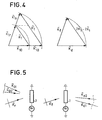
- the method of the invention is based on the non-linearities induced by the diffraction of a phase structure recorded at two wavelengths ⁇ 1 and ; as illustrated in FIG. 4, if we consider an object plane wavefront at these two wavelengths correspond two wave vectors K 10 and collinear, the same is true for wave vectors K 1r and .
- the resulting vectors K 1 and are homothetic to each other, these two wave vectors representative of the networks of strata are therefore parallel:
- a light intensity I 1 at recording it can be broken down into an average component of amplitude I o and a sinusoidal component of amplitude Im1.
- l o I m1
- ⁇ O.
- phase modulation on the reading wave is a function of the resulting illumination, so it can be expressed in the form:
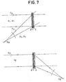
- FIG. 6 illustrates the method according to the invention.
- the recording is carried out in two successive phases with two distinct wavelengths: at a wavelength ⁇ 1 for which there are the vectors K r ' K 1 and K 20 whose ends are therefore on a circle and at another wavelength and .
- K 1 wave vector of the reading beam
- K d1 and K d2 wave vectors of the diffraction beams corresponding to the wave vectors K o1 and K o2 are on the same circle due to the Bragg incidence, K 1 being parallel to K r .
- Reading takes place at a new wavelength as defined above.
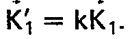
- FIG. 7 shows an example of operation with the two wavelengths ⁇ 1 and ⁇ ' 1 .
- composition scheme of the wave vectors is maintained whatever the orientation of one of the wave vectors K 1 for example, a complex image is therefore diffracted in its entirety with change in wavelength between the registration and reading.
- a complex image is therefore diffracted in its entirety with change in wavelength between the registration and reading.
- the recording wavelengths are for example obtained from a Krypton laser, He-Se, or dye laser.
- this proposed device ensures the diffraction of a thick phase structure for any visible or infrared reading wavelength.
- the applications of this invention are in the field of holographic optical components recorded by variation of index on supports of the "gelatin" type; the invention is also of great interest for the non-destructive reading (outside the absorption band) of information recorded by photorefractive effect in the BSO crystals for example (recording in the vicinity of the absorption band).
Description
- L'invention se rapporte à un procédé holographique d'enregistrement-lecture.
- Dans les dispositifs d'enregistrement-lecture holographiques connus l'hologramme d'un objet est enregistré à partir d'une onde objet diffractée par l'objet dont on souhaite enregistrer l'hologramme et d'une onde de référence correspondante. On dipose, actuellement, de matériaux permettant l'inscription des réseaux ou hologrammes de phase à efficacité de diffraction élevée, telle la gelatine bicromatée, ou fonctionnant en temps réele tels cristaux électro-optiques tel l'oxyde de bismuth-silicium. Ces matériaux sont »épais« par rapport au pas moyen des strates photoinduites, et leur comportement à l'inscription et à la lecture est décrit par le formalisme des ondes couplées; notamment l'effet Bragg de sélectivité angulaire peut y être utilisé.
- La lecture des hologrammes s'effectue par éclairage au moyen d'un rayonnement optique cohérent, par exemple au moyen du faisceau de référence qui a été utilicsé à l'enregistrement. Pour que cette lecture n'entraine pas l'effacement de l'hologramme inscrit, il est nécessaire que la variation spatiale d'indice précédemment induite ne soit pas sensiblement modifiée par un tel rayonnement.
- Si l'onde objet est complexe et contient donc un ensemble de vecteurs d'ondes non colinéaires, il résulte dans le support photosensible un spectre de vecteurs résultants de longueurs et d'orientations différentes. Dans le domaine de l'art connu il n'est pas possible alors de diffracter une image dans les conditions optima si la longueur d'onde de lecture est différente de celle utilisée pour l'inscription holographique dans le matériau épais. Il s'agit là d'une limitation importante. En effet pour une information enregistrée par effet photoréfractif dans les cristaux électro-optiques de type oxyde de bismuth-silicium (BSO), la relecture à la même longueur d'onde efface l'information par relaxation du champ de charge d'espace.
- Si l'on a affaire à une lecture non destructive, il peut être intéressant de lire avec un rayonnement visible un enregistrement effectué avec des longueurs d'ondes plus faibles. Ainsi les composants optiques sur gélatine bicromatée ou blanchie ont un domaine spectral limité qui va de 0,23 micromètres à 0,58 micromètres environ, ce qui limite considérablement leur utilisation. La méthode d'enregistrement proposée dans la présente invention assure une relecture, dans les conditions de Bragg par une longueur d'onde prise en dehors du domaine de sensibilité spectrale des cristaux de type oxyde de bismuth-silicium (BSO) par exemple.
- Un document de l'art antérieur, à savoir le document »Optics Communications« 31 (1979), pages 301-305 décrit un procédé holographique d'enregistrement-lecture par strates d'indice dans le domaine d'un milieu de stockage photo- excitable. Il consiste à faire interférer dans ledit volume un faisceau issu d'un objet et un faisceau de référence au cours de l'inscription, chacun de ces deux faisceaux comprenant deux rayonnements inscripteurs de longueurs d'ondes distinctes.
- Ce procédé connu utilise une longueur d'onde d'écriture λ1 et dans le milieu de stockage un réseau de strates auquel correspondent deux vecteurs d'onde K1, K2; et une longueur d'onde de lecture À2 avec un vecteur d'onde K, correspondant à cette longueur d'onde, tel que K± _ K1 ±K2. Ce document de l'art connu décrit donc la lecture, par un rayonnement cohérent ayant pour vecteur d'onde dans le milieu de stockage une combinaison linéaire des vecteurs d'onde du rayonnement inscripteur se propageant selon deux incidences différentes.
- Par contre, dans le procédé de l'invention, il y a écriture à deux longueurs d'ondes λ1 et λ1 sous une même incidence et lecture sous une incidence différente et à une troisième longueur d'onde λL.
- Le procédé de l'invention, par rapport au procédé tel que décrit dans le document de l'art connu, présente donc l'avantage de supprimer le problème de positionnement du faisceau d'inscription de longueur d'onde 11 pour atteindre le milieu sous deux incidences e1 et e2. Dans le procédé de l'invention, cette incidence reste constante, seule la longueur d'onde du faisceau inscription doit être changée.
- L'invention a pour objet un procédé holographique d'enregistrement-lecture par strates d'indice dans le volume d'un milieu de stockage photo- excitable nonlinéaire, faisant interférer dans ledit volume un faisceau issu d'un objet et un faisceau de référence, de manière à entrainer l'apparition dans ledit milieu d'un réseau de strates auquel correspondent deux vecteurs d'onde d'inscription distincts, la lecture dudit milieu étant assuré par une source produisant un rayonnement cohérent à une longueur d'onde de lecture différente de la longueur d'onde des faisceaux d'inscription et le vecteur d'onde dans ledit milieu étant une combinaison linéaire de ces vecteurs d'onde d'inscription, caractérisé en ce que ledit procédé consiste à faire interférer, au cours de deux étapes d'inscription successives, les faisceaux de référence et objet de deux rayonnements inscripteurs de longueurs d'ondes d'inscription distinctes produits par deux sources de rayonnement cohérent et projetés, au cours des deux étapes selon les mêmes trajets, en direction dudit objet et en direction dudit milieu.
- Les caractéristiques et avantages de l'invention seront expliqués dans la description ci-après, en référence aux figures annexées où:
- - les figures 1,2 et 3 sont des figures explicatives du fonctionnement d'un dispositif de fart connu;
- - les figures 4, 5 et 6 sont des figures explicatives du procédé selon l'invention;
- - la figure 7 illustre le procédé selon l'invention.
- Pour l'ensemble de la description qui va suivre et pour les figures considérées on se place à l'intérieur du milieu 1. C'est à dire que l'on peut écrire

- Sur la figure 1 on considère deux faisceaux. Un faisceau modulé par un objet linéairement transparent de vecteur d'onde Ko et un faisceau référence de vecteur d'onde Kr. Les franges d'interférence résultant de la superposition de ces deux faisceaux de même longueur d'onde sont enregistrés dans le milieu 1. Ce milieu, à titre d'exemple non limitatif, est constitué d'un matériau photoéfractif polarisé par un champ électrique obtenu au moyen d'une source de tension Vo. Son orientation est telle que le champ électrique produit un effet de variation d'indice par des porteurs de charge crées par photoexcitation. Les variations spatiales d'intensité lumineuse se traduisent instantanément dans ce milieu par des variations spatiales d'indice de réfraction, les plans d'interférence étant, de préférence, quasi perpendiculaires à la direction du champ appliqué.
- Il y a donc création d'un réseau de strates de vecteur d'onde spatial

- Ces relations vectorielles permettent de calculer l'incidence Bragg du faisceau de lecture si la longueur d'onde de celui ci λ' est différente de celle utilisée pour l'inscription du réseau λ. On a: sin


- Comme sur la figure 3 si l'onde objet utilisée est complexe, elle contient un ensemble de vecteurs d'ondes ici Ko1 et Ko2. il en résulte dans le milieu photosensible 1 un spectre de vecteurs d'onde résultant Ki de longueur et d'orientation différen- tes; ici K1 et K2 tels que K1 = Kr - Ko1 et K2 = Kr - Ko2. Ainsi, dans le cas où l'onde de lecture et l'onde de référence n'ont pas des vecteurs d'onde tels que K1 = Kr, on ne pourra pas diffracter une image dans les conditions optima si la longueur d'onde de lecture est différente de celle utilisée par l'inscription holographique dans ce milieu épais. En effet dans ce cas on a Θ' ≠ 0 avec sin

- Le procédé selon l'invention assure une relecture, dans les conditions de Bragg par une onde de lecture de longueur d'onde λ1, différente de la longueur d'onde du faisceau référence, prise en dehors du domaine de sensibilité spectrale des cristaux BSO par exemple.
- Cette relecture est possible en volume, car on adopte, lors de deux enregistrements successifs, les mêmes conditions d'éclairement de l'objet, afin que les rayonnements qui interférent dans le milieu donnent aux strates des orientations identiques mais des espacements qui varient en fonction des longueurs d'ondes utilisées.
- Ceci dit, le procédé de l'invention est basé sur les non-linéarités induites par la diffraction d'une structure de phase enregistrée à deux longueurs d'onde λ1 et


- Si l'on considère une intensité lumineuse I1 à l'enregistrement, elle peut être décomposée en une composante moyenne d'amplitude Io et une composante sinusoïdale d'amplitude Im1. Si r est le vecteur position unité de l'origine, à n'importe quel point du milieu on a: =r ix + jy + kz (i, j, k étant les vecteurs unités dirigés suivant les axes x, y,z),onal1=Io+Im1Cos(K1· r+Δ). On peut considérer lo= Im1, et la constante arbitraire de phase Δ=O.
- Ainsi I1 = Io + Io Cos (
K 1r ). - Si l'on considère le vecteur i par exemple colinéaire K1 on a: K1· r = |K1||i|.
- Ainsi I1 = Io+Io Cos |K1||
i |. - Si l'on considère deux vecteurs parallèles
K 1 et K'1 leurs intensités lumineuses respectives sont de la même forme et on a l'intensité résultante: - I= I1 + I1 = 21o+ lo Cos|K1|| i |+lo Cos|

- Mais les matériaux considérés ne sont pas sensible à la composante continue, ils sont sensibles au gradient d'indice aussi:

- La modulation en phase sur l'onde de lecture est fonction de l'illumination résultante, aussi on peut l'exprimer sous la forme:


- Cette décomposition en fonction de Bessel montre que si deux vecteurs d'onde K1 et

-
K 1 1 ±
- 2
K ±2
- 2


- 2
K 1 ±
- L'un ou l'autre de ces vecteurs d'onde permettra de diffracter dans le milieu avec les conditions de Bragg pour la longueur d'onde de lecture λ1 telle que si on se place dans le cas du vecteur Ki1 =


 = k K2. De par la démonstration faite précédemment, il existe donc en plus des réseaux de strates élémentaires une série de configurations possibles de vecteurs résultants Ki1 et Ki2 correspondant à la combinaison des vecteurs K1 et


- Ces différents cas de figure sont aussi valables avec un nombre supérieur de vecteurs d'onde du faisceau d'onde complexe modulé par l'objet. On peut ainsi effectuer la lecture à l'incidence Bragg et ce dans une direction parallèle à la direction du faisceau référence du fait de ce rapport homothé- tique liant les vecteurs Ki1 et Ki1 et Ki2 et K2. Sur la figure 6 on a donc pris a = 2 et b = -2.
- Les extrémités des vecteurs K1: vecteur d'onde du faisceau de lecture, et Kd1 et Kd2: vecteurs d'onde des faisceaux de diffraction correspondant aux vecteurs d'onde Ko1 et Ko2 sont sur un même cercle du fait de l'incidence Bragg, K1 étant parallèle à Kr.
- La lecture s'effectue à une nouvelle longueur d'onde telle que défini précédemment.
- Pour l'ensemble de la description qui précède et pour les figures annexées, on s'est placé à l'intérieur du milieu 1. Mais ces figures ainsi que les formules restent valable en dehors du milieu, à condition toutefois de considérer un milieu dont l'indice varie peu pour les longueurs d'onde considérées, par exemple à 10-3 près. Ceci est vrai pour des matériaux à faible dispersion, ce qui est le cas de la gélatine. Pour des matériaux tel le BSO, on peut compenser la variation d'indice due à la dispersion par l'adjonction de deux lames passives transparentes 2 de variation d'indice opposée à celle du milieu 1 et enserrant celui-ci, pour compenser le chromatisme qui existe dans ce milieu. Ce qui peut être parfaitement réalisé par un réseau par exemple.
- La figure 7 représente un exemple de fonctionnement avec les deux longueurs d'onde λ1 et λ'1.
- Le schéma de composition des vecteurs d'ondes est maintenu quelle que soit l'orientation de l'un des vecteurs d'onde K1 par exemple, une image complexe est donc diffractée dans son intégralité avec changement de longueur d'onde entre l'inscription et la lecture. En guise d'exemple, on peut considérer la lecture non destructive d'un hologramme de volume enregistré dans un cristal BSO.
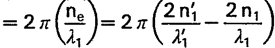
- On considère une longueur d'onde de lecture (laser semiconducteur) de 800 nm <λi < 1000 nm; n1 = 2,45 et des longueurs d'onde d'inscription
- λ1 = 450 nm; ni = 2,7
- λ'1 = 550 nm; n'1 = 2,6
- Soit

- On a alors λ1 = 962,5 nm comme longueur d'onde de lecture.
- En choisissant un couple de longueurs d'ondes d'inscription bleu-vert, on peut donc relire l'information de façon non destructive à l'aide d'un laser semiconducteur émettant dans l'infra-rouge. Les longueurs d'ondes d'enregistrement sont par exemple obtenus à partir d'un laser Krypton, He-Se, ou laser à colorant.
- Ainsi ce dispositif proposé assure la diffraction d'une structure de phase épaisse pour une longueur d'onde de lecture quelconque visible ou infra-rouge.
- Ainsi les applications de cette invention se situent dans le domaine des composants optiques holographiques enregistrés par variation d'indice sur des supports du type »gélatine«; l'invention présente également un grand intérêt pour la lecture non destructive (en dehors de la bande d'absorption) d'informations enregistrés par effet photoréfractif dans les cristaux BSO par exemple (enregistrement au voisinage de la bande d'absorption).
La variation de l'indice de réfraction est linéairement proportionnelle à l'exposition, aussi l'indice de réfraction peut être exprimé sous une forme similaire à celle de l'intensité lumineuse.
Claims (7)
Applications Claiming Priority (2)
| Application Number | Priority Date | Filing Date | Title |
|---|---|---|---|
| FR8113322A FR2509485A1 (fr) | 1981-07-07 | 1981-07-07 | Procede holographique d'enregistrement-lecture et dispositif mettant en oeuvre ce procede |
| FR8113322 | 1981-07-07 |
Publications (2)
| Publication Number | Publication Date |
|---|---|
| EP0069652A1 EP0069652A1 (fr) | 1983-01-12 |
| EP0069652B1 true EP0069652B1 (fr) | 1985-09-11 |
Family
ID=9260287
Family Applications (1)
| Application Number | Title | Priority Date | Filing Date |
|---|---|---|---|
| EP82401206A Expired EP0069652B1 (fr) | 1981-07-07 | 1982-06-29 | Procédé holographique d'enregistrement-lecture |
Country Status (5)
| Country | Link |
|---|---|
| US (1) | US4592618A (fr) |
| EP (1) | EP0069652B1 (fr) |
| JP (1) | JPS5817475A (fr) |
| DE (1) | DE3266190D1 (fr) |
| FR (1) | FR2509485A1 (fr) |
Families Citing this family (13)
| Publication number | Priority date | Publication date | Assignee | Title |
|---|---|---|---|---|
| FR2544151B1 (fr) * | 1983-04-06 | 1985-06-21 | Thomson Csf | Dispositif de commutation spatiale de faisceaux optiques |
| US4830442A (en) * | 1987-01-06 | 1989-05-16 | Hughes Aircraft Company | Off-axis holographic instrument illuminator |
| US4888260A (en) * | 1987-08-10 | 1989-12-19 | Polaroid Corporation | Volume phase reflection holograms and methods for fabricating them |
| US5162928A (en) * | 1988-11-02 | 1992-11-10 | Canon Kabushiki Kaisha | Head-up display apparatus |
| US4913534A (en) * | 1989-03-02 | 1990-04-03 | Administrator Of The National Aeronautics And Space Administration | Real-time dynamic holographic image storage device |
| FR2696014B1 (fr) * | 1992-09-18 | 1994-11-04 | Thomson Csf | Miroir à conjugaison de phase. |
| US5696613A (en) * | 1993-08-20 | 1997-12-09 | Tamarack Storage Devices | Method and apparatus for multiplexing data in different planes of incidence of a thin holographic storage media |
| FR2711878B1 (fr) * | 1993-10-29 | 1995-12-15 | Thomson Csf | Dispositif de visualisation couleurs et procédé de réalisation. |
| US5739929A (en) * | 1996-06-17 | 1998-04-14 | International Business Machines Corporation | Method and device for holographic storage |
| FR2755516B1 (fr) | 1996-11-05 | 1999-01-22 | Thomson Csf | Dispositif compact d'illumination |
| FR2819061B1 (fr) * | 2000-12-28 | 2003-04-11 | Thomson Csf | Dispositif de controle de polarisation dans une liaison optique |
| WO2003094157A1 (fr) * | 2002-05-02 | 2003-11-13 | Discovision Associates | Procede et appareil d'enregistrement sur une memoire optique a diffraction multicouche et de lecture dans une telle memoire |
| US9557711B2 (en) * | 2013-12-28 | 2017-01-31 | Vadim RAKHOVSKY | Method of static scaling of image in holographic lithography |
Family Cites Families (8)
| Publication number | Priority date | Publication date | Assignee | Title |
|---|---|---|---|---|
| US3503050A (en) * | 1965-12-30 | 1970-03-24 | Ibm | Wave energy recording in radiation sensitive medium |
| US3519323A (en) * | 1966-08-30 | 1970-07-07 | Bell Telephone Labor Inc | Hologram method and apparatus for recording and reconstructing multicolor images |
| FR1546333A (fr) * | 1967-12-05 | 1968-11-15 | Philips Nv | Dispositif pour observer un hologramme à l'aide de lumière blanche, et grille de déviation à utiliser dans ce dispositif |
| US3617274A (en) * | 1968-03-29 | 1971-11-02 | Bell Telephone Labor Inc | Hardened gelatin holographic recording medium |
| US3603668A (en) * | 1970-01-29 | 1971-09-07 | Philips Corp | Composite diffraction grating formed from superimposed aligned gratings |
| US3754808A (en) * | 1971-08-30 | 1973-08-28 | Us Navy | Holographic readout system employing predispersion diffraction grating |
| US4103346A (en) * | 1977-02-16 | 1978-07-25 | International Business Machines Corporation | Non-destructive readout scheme for holographic storage system |
| US4451114A (en) * | 1981-12-30 | 1984-05-29 | Peter Nicholson | Method for recording and reconstructing pulse laser holograms in color |
-
1981
- 1981-07-07 FR FR8113322A patent/FR2509485A1/fr active Granted
-
1982
- 1982-06-29 EP EP82401206A patent/EP0069652B1/fr not_active Expired
- 1982-06-29 DE DE8282401206T patent/DE3266190D1/de not_active Expired
- 1982-07-02 US US06/394,723 patent/US4592618A/en not_active Expired - Fee Related
- 1982-07-06 JP JP57117648A patent/JPS5817475A/ja active Pending
Non-Patent Citations (3)
| Title |
|---|
| APPLIED PHYSICS LETTERS, vol.29, no.9, 1er novembre 1976, American Institute of Physics, New York (US), J.P. HUIGNARD et al.: "High-sensitivity read-write volume holographic storage in Bil2Si020 and Bil2Ge020 crystals", pages 591-593 * |
| JOURNAL OF THE OPTICAL SOCIETY OF AMERICA, vol.65, no.6, juin 1975, New York (US), S.K. CASE: "Coupled-wave theory for multiply exposed thick holographic gratings", pages 724-729 * |
| OPTICS COMMUNICATIONS, vol.31, no.3, décembre 1979, Amsterdam (NL), M.P. PETROV et al.: "Light diffraction and nonlinear image processing in electroopticBil2Si020 crystals", pages 301-305 * |
Also Published As
| Publication number | Publication date |
|---|---|
| US4592618A (en) | 1986-06-03 |
| DE3266190D1 (en) | 1985-10-17 |
| EP0069652A1 (fr) | 1983-01-12 |
| JPS5817475A (ja) | 1983-02-01 |
| FR2509485A1 (fr) | 1983-01-14 |
| FR2509485B1 (fr) | 1983-10-21 |
Similar Documents
| Publication | Publication Date | Title |
|---|---|---|
| EP0069652B1 (fr) | Procédé holographique d'enregistrement-lecture | |
| Marrakchi et al. | Physical characterization of the photorefractive incoherent-to-coherent optical converter | |
| Bräuchle et al. | Holographic methods for the investigation of photochemical and photophysical properties of molecules | |
| EP0061360B1 (fr) | Dispositif optique d'entretien d'une impulsion d'énergie radiante circulant dans un guide d'onde monomode, gyromètre et hydrophone comportant un tel dispositif | |
| US3544189A (en) | Holography using a poled ferroelectric recording material | |
| Nisenson et al. | Real time optical processing with Bi 12 SiO 20 PROM | |
| FR2518766A1 (fr) | Dispositif de commutation de faisceaux optiques et central telephonique comprenant un tel dispositif | |
| Tiziani | Real-time metrology with BSO crystals | |
| EP0138668B1 (fr) | Dispositif d'enregistrement d'une image cohérente dans une cavité optique multimode | |
| EP0095960B1 (fr) | Dispositif de mise en mémoire d'une image cohérente dans une cavité optique multimode | |
| EP0053052B1 (fr) | Dispositif d'interférométrie pour la visualisation en temps réel des déformations de structures vibrantes | |
| EP0058592B1 (fr) | Dispositif optique transformateur de Fourier, et corrélateur optique mettant en oeuvre ce dispositif optique transformateur de Fourier | |
| Blanche | Holographic recording media and devices | |
| US3694657A (en) | Holographic correlator with a folded path acoustic cell input | |
| JPH05273503A (ja) | 空間光変調器および空間光変調方法 | |
| EP0827621B1 (fr) | Memoire de masse optique, ainsi que procedes de fabrication d'une telle memoire et procede d'enregistrement et/ou de lecture de donnees dans une telle memoire | |
| Hafiz et al. | Visualization of aerodynamic flow fields using photorefractive crystals | |
| EP0026128B1 (fr) | Dispositif d'enregistrement holographique et système optique de traitement d'information comportant un tel dispositif | |
| Guest et al. | EXCLUSIVE OR processing (binary image subtraction) using thick Fourier holograms | |
| JP4130296B2 (ja) | ホログラフメモリーシステムで用いられる装置と、周期的位相構造を入力データ面にマッピングする方法 | |
| EP0040116B1 (fr) | Dispositif de prise de vue à champ étendu | |
| FR2544151A1 (fr) | Dispositif de commutation spatiale de faisceaux optiques | |
| Lindegren et al. | Holography at the telescope-an interferometric method for recording stellar spectra in thick photographic emulsions | |
| Cherkasov et al. | Real-time optical information recording using molecular photothermoplastic heterostructures | |
| FR2528993A1 (fr) | Dispositif d'eclairement d'un milieu electro-optique pour enregistrer des hologrammes en temps reel |
Legal Events
| Date | Code | Title | Description |
|---|---|---|---|
| PUAI | Public reference made under article 153(3) epc to a published international application that has entered the european phase |
Free format text: ORIGINAL CODE: 0009012 |
|
| AK | Designated contracting states |
Designated state(s): DE GB NL SE |
|
| 17P | Request for examination filed |
Effective date: 19830129 |
|
| GRAA | (expected) grant |
Free format text: ORIGINAL CODE: 0009210 |
|
| AK | Designated contracting states |
Designated state(s): DE GB NL SE |
|
| REF | Corresponds to: |
Ref document number: 3266190 Country of ref document: DE Date of ref document: 19851017 |
|
| PLBE | No opposition filed within time limit |
Free format text: ORIGINAL CODE: 0009261 |
|
| STAA | Information on the status of an ep patent application or granted ep patent |
Free format text: STATUS: NO OPPOSITION FILED WITHIN TIME LIMIT |
|
| 26N | No opposition filed | ||
| PGFP | Annual fee paid to national office [announced via postgrant information from national office to epo] |
Ref country code: NL Payment date: 19870630 Year of fee payment: 6 |
|
| PG25 | Lapsed in a contracting state [announced via postgrant information from national office to epo] |
Ref country code: SE Effective date: 19890630 |
|
| PG25 | Lapsed in a contracting state [announced via postgrant information from national office to epo] |
Ref country code: NL Effective date: 19900101 |
|
| NLV4 | Nl: lapsed or anulled due to non-payment of the annual fee | ||
| PGFP | Annual fee paid to national office [announced via postgrant information from national office to epo] |
Ref country code: GB Payment date: 19900518 Year of fee payment: 9 |
|
| PGFP | Annual fee paid to national office [announced via postgrant information from national office to epo] |
Ref country code: DE Payment date: 19900519 Year of fee payment: 9 |
|
| PG25 | Lapsed in a contracting state [announced via postgrant information from national office to epo] |
Ref country code: GB Effective date: 19910629 |
|
| GBPC | Gb: european patent ceased through non-payment of renewal fee | ||
| PG25 | Lapsed in a contracting state [announced via postgrant information from national office to epo] |
Ref country code: DE Effective date: 19920401 |
|
| EUG | Se: european patent has lapsed |
Ref document number: 82401206.6 Effective date: 19900412 |