EP0067653A2 - Printing head for ink jet printer - Google Patents
Printing head for ink jet printer Download PDFInfo
- Publication number
- EP0067653A2 EP0067653A2 EP82302955A EP82302955A EP0067653A2 EP 0067653 A2 EP0067653 A2 EP 0067653A2 EP 82302955 A EP82302955 A EP 82302955A EP 82302955 A EP82302955 A EP 82302955A EP 0067653 A2 EP0067653 A2 EP 0067653A2
- Authority
- EP
- European Patent Office
- Prior art keywords
- plate
- ink
- cavities
- printing head
- ink jet
- Prior art date
- Legal status (The legal status is an assumption and is not a legal conclusion. Google has not performed a legal analysis and makes no representation as to the accuracy of the status listed.)
- Withdrawn
Links
Images


Classifications
-
- B—PERFORMING OPERATIONS; TRANSPORTING
- B41—PRINTING; LINING MACHINES; TYPEWRITERS; STAMPS
- B41J—TYPEWRITERS; SELECTIVE PRINTING MECHANISMS, i.e. MECHANISMS PRINTING OTHERWISE THAN FROM A FORME; CORRECTION OF TYPOGRAPHICAL ERRORS
- B41J2/00—Typewriters or selective printing mechanisms characterised by the printing or marking process for which they are designed
- B41J2/005—Typewriters or selective printing mechanisms characterised by the printing or marking process for which they are designed characterised by bringing liquid or particles selectively into contact with a printing material
- B41J2/01—Ink jet
- B41J2/135—Nozzles
- B41J2/14—Structure thereof only for on-demand ink jet heads
- B41J2/14201—Structure of print heads with piezoelectric elements
- B41J2/14233—Structure of print heads with piezoelectric elements of film type, deformed by bending and disposed on a diaphragm
-
- B—PERFORMING OPERATIONS; TRANSPORTING
- B41—PRINTING; LINING MACHINES; TYPEWRITERS; STAMPS
- B41J—TYPEWRITERS; SELECTIVE PRINTING MECHANISMS, i.e. MECHANISMS PRINTING OTHERWISE THAN FROM A FORME; CORRECTION OF TYPOGRAPHICAL ERRORS
- B41J2/00—Typewriters or selective printing mechanisms characterised by the printing or marking process for which they are designed
- B41J2/005—Typewriters or selective printing mechanisms characterised by the printing or marking process for which they are designed characterised by bringing liquid or particles selectively into contact with a printing material
- B41J2/01—Ink jet
- B41J2/135—Nozzles
- B41J2/14—Structure thereof only for on-demand ink jet heads
- B41J2002/14379—Edge shooter
Definitions
- This invention relates to a printing head for an ink jet printer, and more particularly to a printing head for a drop on-demand type ink jet printer.
- Ink jet printers can be broadly classified into a drop on-demand type which jets ink droplets whenever necessary and a continuous type which jets the ink droplets constantly.
- the continuous type printer requires a high voltage power source on the order of kilo-volts to deflect the ink droplets while constantly jetting the ink.
- the printer also refreshes unnecessary ink so that an ink circulating mechanism has a complicated construction. These altogether increase the size of the printer.
- the drop on-demand type printer can be constructed smaller and can jet the ink droplets at a lower voltage (e.g. about 100 V).
- the drop on-demand printer does not need the-ink circulating mechanism because the ink is jetted only when necessary, thus making it possible to simplify the ink feed mechanism and reduce the size of the printer.
- the drop on-demand is disadvantageous in comparison with the continuous type because it has lower resolution and speed performance. Its driving frequency is generally lower than that of the continuous type.
- a plurality of ink projection chambers are arranged in this drop on-demand type ink jet printer so as to realize a jet head having a multi-nozzle arrangement and to improve the speed performance of the ink jet printer.
- the nozzles are disposed merely plane-wise in the conventional multi-nozzle ink jet head, the nozzle pitch (or nozzle gap) can not be made sufficiently small and hence, sufficient resolution can not be attained.
- the ink jet printer using the first method (i) has the critical problem in that the printing speed is extremely reduced, and the printer using the second method (ii) has the problem that the cost of production of the printing heads and their associated components (such as the ink feed passages) becomes higher in proportion to the number of printing heads, increasing the cost of production of the printer as a whole.
- Figure 1 is a sectional view showing the construction of the conventional printing head in the drop on-demand type ink jet printer.
- Reference numeral 1 represents a first plate having a cavity la formed thereon.
- a second plate 2 which is a flexible wall, is disposed on the cavity la and defines a projection chamber 3 together with the cavity la.
- the ink is fully charged into the projection chamber 3.
- a piezoelectric crystal 4 is bonded to the second plate 2, and deforms the flexible second plate 2 in response to an external signal, reducing the volume of the projection chamber and jetting the ink therein out through a nozzle 5.
- the second plate 2 In order to function as a flexible wall, the second plate 2 must be as thin as on the order of several hundreds of microns and since the accuracy of finishing the thickness is closely related with the speed of the ink droplets, the threshold frequency and stability, the error in thickness must generally be as high as within 10 ym. Hence, it has conventionally been finished by lapping.
- the number of projection chambers must be increased or the area of the second plate 2 must be increased.
- the present invention is directed to provide a printing head for an ink . jet printer which can easily be constructed in a multi-nozzle arrangement and can be produced economically.
- the construction which accomplishes this object of the present invention comprises a first plate having a cavity formed by etching and whose wall serves as the flexible wall deforming in response to an external signal, and a second plate disposed opposite the first plate so as to make the cavity to form a projection chamber.
- the construction to accomplish this object of the present invention is characterized in that projection chambers each having flexible walls deforming in response to an external signal are disposed on both sides of a second plate.
- Fiugre 16 shows the arrangement of nozzles in still another embodiment of the present invention.
- Figure 2 is a sectional view showing the printing head in accordance with an embodiment of the present invention, in which reference numeral 11 represents a first plate and reference numeral 12 represents a second plate which is disposed so as to oppose the first plate 11.
- a cavity lla is formed by etching on the first plate 11 and its reduced thickness portion forms a flexible wall 11b.
- the surface of the second plate 12 and the inner surface of the cavity lla together form a projection chamber 13 which receives ink 16 fed from an ink reservoir chamber 14 through a conduit 15.
- Reference numeral 17 represents a piezoelectric crystal bonded to the flexible wall llb of the first plate 11 and driven by a pulse generator 18 which delivers electric pulses in accordance with recorded data.
- Reference numeral 19 represents a nozzle for jetting the ink 16 inside the projection chamber 13 out.
- the tip of the nozzle has an orifice 20.
- a plurality of nozzles 19, orifices 20 and projection chambers 13 are disposed in the direction perpendicular to the drawing,
- the projection chamber 13 of the printing head as well as the nozzle 19 thus constructed are filled with ink 16 supplied from the ink reservoir chamber 14 through the conduit 15.
- the flexible wall llb also undergoes inward deformation so that the volume of the projection chamber 13 rapidly decreases and a part of the ink 16 inside the projection chamber 13 is jetted at a high speed out through the nozzle 19 and orifice 20.
- the other part of the ink returns to the ink reservoir chamber 14 through the conduit 15.
- the ink that has been jetted out through nozzle 19 and orifice 20 turns into spherical ink droplets due to the surface tension after jetting..
- the diameter of the ink droplet is determined by the diameter of the orifice 20, the voltage level of the electric pulse, its rise time constant and its width.
- the volume of _ the projection chamber 13 returns to its original state after the passage of time corresponding to the pulse width of the electric pulse, and when the volume returns to its original state the projection chamber 13 receives the ink 16 fed from the ink reservoir chamber 14.
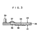
- Figure 3 is a sectional view which shows another embodiment of the present invention, which is different from the embodiment shown in Figure 2 in that it has a pressure absorbing chamber.
- reference numerals 21 and 22 represent the first plate and the second plate opposing the first plate 21, respectively.
- Figure 4 shows: a cavity 23 for forming the pressure absorbing chamber, projection chamber-forming cavities (apertures ) 24 (twelve cavities 24-1, 24-2, ..., 24-12 are shown in the drawing) connected with the cavity 23, nozzle-forming cavities 25 (twelve cavities 25-1, 25-2, ..., 25-12 are shown in the drawing), radial cavities 26 for connecting the projection chamber-forming cavities 24 with the nozzle-forming cavities 25 (twelve radial cavities 26-1, 26-2, ..., 26-12 are shown in the drawing), an ink inflow port 27, an elongated cavities 28 for guiding the ink to the cavity 23 and an assembly jig hole 29, all formed by etching on the first plate 21.
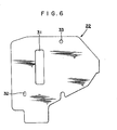
- FIG. 6 shows the second plate 22, in which are formed an aperture 31 for forming the pressure absorbing chamber, an ink inflow port 32 and an assembly jig hole 33.
- Both first and second plates 21, 22 are made of photosensitive glass such as "Photoceram", the trade name of a product of Corning Glass Co., U.S., for example.
- Photoceram the trade name of a product of Corning Glass Co., U.S., for example.
- the photoceram plate thus exposed and developed is dipped in a hydrogen fluoride solution and the crystallized portion is deeply etched.
- the vitreous portion is also etched by the hydrogen fluoride solution but the degree of etching is about 1/50 that of the crystallized portion and is substantially negligible.
- Photoceram plates thus etched are used for both of the first and second plates 21, 22.
- the first and second plates 21, 22 are bonded by a thermal bonding (or interfusion) technique. In this technique, the joint surfaces are accurately polished and brought into intimate contact. The surfaces are kept under such a state at a high temperature (at 800°C or above in the case of photoceram) for several hours so as to bond them together by means of the molecular force between them.
- each.of projection chambers 34 (34-1, 34-2, ..., 34-12) and nozzles 35 (35-1, 35-2, ..., 35-12) are formed between them.
- the pressure absorbing chamber 36 for absorbing the pressure which is transmitted to the ink reservoir chamber when the ink droplets are jetted is formed close to the center of the plates 21 and 22.
- a flexible cover 37 covers the opening of this pressure absorbing chamber 36.
- Reference numeral 38 represents twelve (38-1, 38-2, ..., 38-12) piezoelectric crystals that are bonded to the flexible walls 30 of the first plate 21 and reference numeral 39 represents a connector for receiving the feed of the ink.
- one (assumed hereby to be 38-1) receives an electric pulse causing the flexible wall 30-1 to which it is bonded to deform inward and rapidly decrease the volume of the projection chamber 34-1 so that the ink therein jets out via the nozzle 35-1.
- part of the ink moves in the direction opposite the nozzle 35-1.
- -the volume of the pressure absorbing chamber 36 temporarily increases and absorbs the rise of the liquid pressure, so the ink droplets are not jetted by nozzles other than the nozzle 35-1.
- the cavities are formed by etching on the first plate and the walls of the cavities are used as the flexible walls in the present invention.
- a suitable thickness can be selected for both first and second plates without any problem of accuracy of finishing.
- the present invention makes it possible to select the thickness of both the first and second plates irrespective of the thickness of the flexible walls and hence, to use the first and second plates having a greater surface area. This makes it possible to realize a printing head having a multi-nozzle construction.
- the cavities can be shaped by etching and may be disposed so as to merely oppose the plates, the printing head can be produced economically.
- FIG. 7 is a sectional view of the printing head in accordance with still another embodiment of the present invention.
- reference numeral 41 represents a second plate and reference numerals 42 and 43 represent first plates disposed on both sides of the second plate 41.
- Cavities 42a and 43a are formed on both first plates 42, 43, respectively, and their reduced thickness portions serves as flexible walls 42b and 43b, respectively.
- Projection chambers 44, 45 are formed between the surfaces of the second plate 41 and the inner surfaces of the cavities 42a, 43a, respectively, and receive ink 16 fed from ink reservoir chamber 14 through conduit 15.
- Reference numerals 49 and 50 represent piezoelectric crystals that are bonded to the flexible walls 42b, 43b of the first plates 42, 43 and are driven by the pulse generator 18 which delivers the electric pulses in accordance with recorded data.
- Reference numerals 52 and 53 represent the nozzles for jetting and the ink 16 inside the projection chambers 44, 45. Orifices 54, 55 are formed at the tips of the nozzles 52, 53, respectively. A plurality of nozzles 52, 53, orifices 54, 55 and projection chambers 44, 45 are disposed in the direction perpendicular to the drawing.
- the projection chambers 44, 45 and nozzles 52, 53 of the printing head thus constructed are filled up with the ink 16 supplied from ink reservoir chamber 14 through conduit 15. Accordingly, when an electric pulse causing inward deformation of the piezoelectric crystal is applied to a specific piezoelectric crystal, such as the piezoelectric crystal 49 for example, the flexible wall 42b also undergoes inward deformation so that the volume of the projection chamber 44 is rapidly reduced and a part of the ink 16 therein jets out at high speed through the nozzle 52 and the orifice 54. In the other direction, the other part returns to the ink reservoir chamber 14 through the conduit 15.
- a specific piezoelectric crystal such as the piezoelectric crystal 49 for example
- the ink jetted outside through the nozzle 52 and the orifice 54 turns into spherical ink droplets due to the surface tension immediately after being jetted.
- the diameter of the ink droplet is determined by the inner diameter of the orifice 54, the voltage of the electric pulse, and its rise time constant and pulse width.
- the volume of the projection chamber 44 returns to its original state after the passage of a time corresponding to the pulse width of the electric pulse, and when the volume returns to the original state, the projection chamber 44 receives ink 16 fed from the ink reservoir chamber 14.
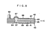
- Figure 8 is a sectional view showing still another embodiment of the present invention. This embodiment is different from the one shown in Figure 7 in that it has the pressure absorbing chamber 57.
- An aperture 64 for forming the pressure absorbing chamber, a round hole 65 for forming an ink inflow port, an elongated hole 66 for guiding the ink to the aperture 64 for forming the pressure absorbing chamber and an assembly jig hole 67 are formed on the second plate 41, as depicted in Figure 9.
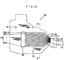
- An aperture 68 for forming the pressure absorbing chamber, cavities 69 (grooves) for forming the projection chambers connected with this aperture 68 (twelve cavities 69-1, 69-2, ..., 69-12 are shown in the drawing), nozzle-forming cavities 70 (twelve cavities 70-1, 70-2, ..., 70-12 are shown in the drawing), radial cavities 71 (twelve cavities 71-1, 71-2, ..., 71-12 are shown in the drawing) connecting the projection chamber-forming cavities 69 with the nozzle-forming cavities 70, an ink inflow port 72 and an assembly jig hole 73 are formed on the first plate 42 as shown in Figure 10.
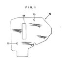
- the aperture 68 for forming the pressure absorbing chamber, the ink inflow port hole 72 and the assembly jig hole 73 penetrate the plate 42 through its back.
- the reduced thickness portions of the projection chamber forming cavities 69 form flexible walls 74 (corresponding to the cavities 69 and represented by 74-1, 74-2, ..., 74-12).
- the first plate 43 has substantially the same shape and construction as the other first plate 42. As shown in Figure 13 formed in first plate 43 are: a cavity 75 for forming the pressure absorbing chamber, projection chamber-forming cavities 7 6 (twelve cavities 76-1, 76-2, ..., 76-12 are shown in the drawing) connected with the cavity 75, nozzle-forming cavities 77 (twelve cavities 77-1, 77-2, ..., 77-12 are shown in the drawing), radial cavities 78 (twelve cavities 78-1, 78-2, ..., 78-12 are shown in the drawing) for connecting the projection chamber-forming cavities 76 with the nozzle-forming cavities 77, an ink inflow port 79 and an assembly jig hole 80.
- the reduced thickness portions at the bottom of the projection chamber-forming cavities 76 form flexible walls 81 (corresponding to the cavities 76 and represented by 81-1, 81-2, ..., 81-12).
- the second plate 41 and the first plates 42, 43 are made of photosensitive glass such as "Photoceram", the trade name of a product of Corning Glass Co., U.S., for example.
- the thus etched photoceram plate is used for both second and first plates 41, 42, 43.
- the second plate 41 is bonded to the first plates 42, 43 by a bonding technique called "thermal bonding" (or “interfusion”).
- twelve each of projection chambers 82 (82-1, 82-2, ..., 82-12) and nozzles 83 (83-1, 83-2, ..., 83-12) are formed on one side of the second plate 41 and twelve each of projection chambers 84 (84-1, 84-2, ..., 84-12) and nozzles 85 (85-1, 85-2, ..., 85-12) are formed on the other side.
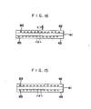
- Figure 15 shows the arrangement of the nozzles 83 and 85 thus aligned.
- the pressure absorbing chamber 57 for absorbing the pressure which is transmitted to the ink reservoir chamber at the time of jetting of the ink droplets is formed close to the center of the plates 41, 42, 43.
- a flexible film 87 covers the opening of the pressure absorbing chamber 57.
- Rerefence numerals 88 and 89 represent twenty-four piezoelectric crystals (88-1, 88-2, ..., 88-12 and 89-1, 89-2, ..., 89-12) that are bonded to the flexible walls 74 and 81 of the first plates 42 and 43, respectively.
- Reference numeral 90 represents a connector for receiving the feed of ink.
- the operation of the printing head constructed as described above is the same as that of the embodiment shown in Figure 7.
- one hereinafter assumed to be the piezoelectric crystal 89-1 receives an electric pulse and deforms the flexible wall 74-1 to which it is bonded inward, drastically reducing the volume of the projection chamber 82-1 having the flexible wall 74-1, and thereby jetting the ink inside the chamber out through the nozzle 83-1.
- a part of the ink moves in the direction opposite the nozzle 83-1.
- the volume of the pressure absorbing chamber 57 temporarily increases and absorbs the liquid pressure rise, the ink droplets are not jetted from nozzles other than the nozzle 83-1.
- the nozzles 83, 85 in a zigzag arrangement by deviating them a distance corresponding to a half pitch of the nozzles shown in Figure 16.
- the pitch of the entire nozzles 83, 85 becomes a half of the pitch (d) of the nozzles 83 or 85.
- this embodiment employs the fundamental construction that projection chambers having flexible walls which deform in response to external signals are formed on both sides of the second plate.
- a printing head having an extremely simplified construction can be realized.
- the printing head can be produced easily and economically especially by forming the cavities having flexible walls on first plates and interposing the second plate between these first plates, or by forming the cavities by etching.
- the present invention makes it possible to arrange the nozzles with a high density and to realize high speed printing with high resolution.
- the arrangement shown in Figure 15 realizes high speed while the arrangement shown in Figure 16 realizes high resolution.
Abstract
A printing head for an ink jet printer comprising a first plate 11 having a cavity 11a a formed by etching and whose wall serves as the flexible wall deforming in response to an external signal, and a second plate 12 disposed opposite the first plate 1 so as to make the cavity to form a projection chamber 13. Projection chambers each having flexible walls deforming in response to an external signal may be disposed on both sides of a second plate.
Description
- This invention relates to a printing head for an ink jet printer, and more particularly to a printing head for a drop on-demand type ink jet printer.
- Ink jet printers can be broadly classified into a drop on-demand type which jets ink droplets whenever necessary and a continuous type which jets the ink droplets constantly.
- The continuous type printer requires a high voltage power source on the order of kilo-volts to deflect the ink droplets while constantly jetting the ink. The printer also refreshes unnecessary ink so that an ink circulating mechanism has a complicated construction. These altogether increase the size of the printer. In comparison with the continuous type, the drop on-demand type printer can be constructed smaller and can jet the ink droplets at a lower voltage (e.g. about 100 V). Moreover, the drop on-demand printer does not need the-ink circulating mechanism because the ink is jetted only when necessary, thus making it possible to simplify the ink feed mechanism and reduce the size of the printer.
- It is believed, however, that the drop on-demand is disadvantageous in comparison with the continuous type because it has lower resolution and speed performance. Its driving frequency is generally lower than that of the continuous type. For these reasons, a plurality of ink projection chambers are arranged in this drop on-demand type ink jet printer so as to realize a jet head having a multi-nozzle arrangement and to improve the speed performance of the ink jet printer. However, since the nozzles are disposed merely plane-wise in the conventional multi-nozzle ink jet head, the nozzle pitch (or nozzle gap) can not be made sufficiently small and hence, sufficient resolution can not be attained.
- In order to solve these problems and to enable printing with high resolution, the following two methods (i) and (ii) have been put to practical use:
- (i) After printing the recording paper is deviated by a half pitch, for example, and printed again.
- (ii) Printing heads having the same shape are arranged deviated from one another.
- However, the ink jet printer using the first method (i) has the critical problem in that the printing speed is extremely reduced, and the printer using the second method (ii) has the problem that the cost of production of the printing heads and their associated components (such as the ink feed passages) becomes higher in proportion to the number of printing heads, increasing the cost of production of the printer as a whole.
- Figure 1 is a sectional view showing the construction of the conventional printing head in the drop on-demand type ink jet printer.
Reference numeral 1 represents a first plate having a cavity la formed thereon. Asecond plate 2 which is a flexible wall, is disposed on the cavity la and defines aprojection chamber 3 together with the cavity la. - The ink is fully charged into the
projection chamber 3. - A
piezoelectric crystal 4 is bonded to thesecond plate 2, and deforms the flexiblesecond plate 2 in response to an external signal, reducing the volume of the projection chamber and jetting the ink therein out through anozzle 5. - In order to function as a flexible wall, the
second plate 2 must be as thin as on the order of several hundreds of microns and since the accuracy of finishing the thickness is closely related with the speed of the ink droplets, the threshold frequency and stability, the error in thickness must generally be as high as within 10 ym. Hence, it has conventionally been finished by lapping. - On the other hand, in order to realize a multi-nozzle printing head, the number of projection chambers must be increased or the area of the
second plate 2 must be increased. - However, it is practically difficult to finish a wide
second plate 2 with a high level of accuracy because the second plate is likely to be damaged during lapping. Even if finishing were possible, the number of operations, including checking the thickness, would increase remarkably, thereby encountering again the problem of the production cost. - Still another problem occurs in post-processing after finishing such as in cleaning because the second plate is easily broken when it is cleaned by ultrasonic cleaning, for example. For this reason, the ink jet head of this construction can not substantially permit the multi-nozzle arrangement suf- fucient to provide high resolution.
- In view of the background described above, the present invention is directed to provide a printing head for an ink. jet printer which can easily be constructed in a multi-nozzle arrangement and can be produced economically.
- The construction which accomplishes this object of the present invention comprises a first plate having a cavity formed by etching and whose wall serves as the flexible wall deforming in response to an external signal, and a second plate disposed opposite the first plate so as to make the cavity to form a projection chamber.
- It is another object of the present invention to provide a jet head which enables high speed printing with high resolution and which can be produced at a reduced cost.
- The construction to accomplish this object of the present invention is characterized in that projection chambers each having flexible walls deforming in response to an external signal are disposed on both sides of a second plate.
- These and other objects and features of the present invention will become more apparent from the following description to be taken in conjunction with the accompanying drawings.
-
- Figure 1 is a sectional view showing the drop on-demand type printing head of the prior art;
- Figure 2 is a sectional view showing a printing head in accordance with an embodiment of the present invention.
- Figures 3 through 6 show a printing head in adcordance with another embodiment of the present invention, in which:
- Figure 3 is a sectional view;
- Figure 4 is a plane view showing the appearance of the first plate;
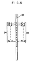
- Figure 5 is a sectional view taken along line A-A of Figure 4; and
- Figure 6 is a plane view showing the appearance of the second plate;
- Figure 7 is a sectional view showing a printing head in accordance with still another embodiment of the present invention;
- Figure 8 is a sectional view showing a printing head in accordance with still another embodiment of the present invention;
- Figure 9 is a plane view of the second plate;
- Figure 10 is a bottom view of one of the first plates;
- Figure 11 is a plane view of the first plate of Figure 10;
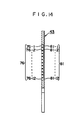
- Figure 12 is a sectional view taken along line A'-A' of Figure 10;
- Figure 13 is a plane view of the other first plate;
- Figure 14 is a sectional view taken along line B-B of Figure 13;
- Figure 15 shows the arrangement of nozzles of the embodiment shown in Figure 8 as viewed from the direction of arrow C; and
- Fiugre 16 shows the arrangement of nozzles in still another embodiment of the present invention.
- Figure 2 is a sectional view showing the printing head in accordance with an embodiment of the present invention, in which reference numeral 11 represents a first plate and
reference numeral 12 represents a second plate which is disposed so as to oppose the first plate 11. A cavity lla is formed by etching on the first plate 11 and its reduced thickness portion forms a flexible wall 11b. The surface of thesecond plate 12 and the inner surface of the cavity lla together form aprojection chamber 13 which receivesink 16 fed from anink reservoir chamber 14 through aconduit 15.Reference numeral 17 represents a piezoelectric crystal bonded to the flexible wall llb of the first plate 11 and driven by apulse generator 18 which delivers electric pulses in accordance with recorded data.Reference numeral 19 represents a nozzle for jetting theink 16 inside theprojection chamber 13 out. The tip of the nozzle has anorifice 20. A plurality ofnozzles 19,orifices 20 andprojection chambers 13 are disposed in the direction perpendicular to the drawing, - The
projection chamber 13 of the printing head as well as thenozzle 19 thus constructed are filled withink 16 supplied from theink reservoir chamber 14 through theconduit 15. When an electric pulse causing inward deformation of thepiezoelectric crystal 17 is applied, the flexible wall llb also undergoes inward deformation so that the volume of theprojection chamber 13 rapidly decreases and a part of theink 16 inside theprojection chamber 13 is jetted at a high speed out through thenozzle 19 andorifice 20. The other part of the ink returns to theink reservoir chamber 14 through theconduit 15. The ink that has been jetted out throughnozzle 19 andorifice 20 turns into spherical ink droplets due to the surface tension after jetting.. The diameter of the ink droplet is determined by the diameter of theorifice 20, the voltage level of the electric pulse, its rise time constant and its width. The volume of _ theprojection chamber 13 returns to its original state after the passage of time corresponding to the pulse width of the electric pulse, and when the volume returns to its original state theprojection chamber 13 receives theink 16 fed from theink reservoir chamber 14. - Figure 3 is a sectional view which shows another embodiment of the present invention, which is different from the embodiment shown in Figure 2 in that it has a pressure absorbing chamber. In Figure 3,
reference numerals first plate 21, respectively. Figure 4 shows: acavity 23 for forming the pressure absorbing chamber, projection chamber-forming cavities (apertures ) 24 (twelve cavities 24-1, 24-2, ..., 24-12 are shown in the drawing) connected with thecavity 23, nozzle-forming cavities 25 (twelve cavities 25-1, 25-2, ..., 25-12 are shown in the drawing),radial cavities 26 for connecting the projection chamber-formingcavities 24 with the nozzle-forming cavities 25 (twelve radial cavities 26-1, 26-2, ..., 26-12 are shown in the drawing), anink inflow port 27, anelongated cavities 28 for guiding the ink to thecavity 23 and anassembly jig hole 29, all formed by etching on thefirst plate 21. The reduced thickness portions at the bottom of the projection chamber-formingcavities 24 form flexible walls 30 (corresponding to thecavities 24 and represented by reference numerals 30-1, 30-2, ..., 30-12). Figure 6 shows thesecond plate 22, in which are formed anaperture 31 for forming the pressure absorbing chamber, anink inflow port 32 and anassembly jig hole 33. - Both first and
second plates - The photoceram plate thus exposed and developed is dipped in a hydrogen fluoride solution and the crystallized portion is deeply etched. Speaking more accurately, the vitreous portion is also etched by the hydrogen fluoride solution but the degree of etching is about 1/50 that of the crystallized portion and is substantially negligible. Photoceram plates thus etched are used for both of the first and
second plates second plates pressure absorbing chamber 36 for absorbing the pressure which is transmitted to the ink reservoir chamber when the ink droplets are jetted is formed close to the center of theplates flexible cover 37 covers the opening of thispressure absorbing chamber 36. -
Reference numeral 38 represents twelve (38-1, 38-2, ..., 38-12) piezoelectric crystals that are bonded to the flexible walls 30 of thefirst plate 21 andreference numeral 39 represents a connector for receiving the feed of the ink. - The operation of the printing head thus constructed is the same as that of the embodiment shown in Figure 2.
- Among the twelve
piezoelectric crystals 38, one (assumed hereby to be 38-1) receives an electric pulse causing the flexible wall 30-1 to which it is bonded to deform inward and rapidly decrease the volume of the projection chamber 34-1 so that the ink therein jets out via the nozzle 35-1. During this operation part of the ink moves in the direction opposite the nozzle 35-1. In this embodiment, however, -the volume of thepressure absorbing chamber 36 temporarily increases and absorbs the rise of the liquid pressure, so the ink droplets are not jetted by nozzles other than the nozzle 35-1. - As described above, the cavities are formed by etching on the first plate and the walls of the cavities are used as the flexible walls in the present invention. Hence, a suitable thickness can be selected for both first and second plates without any problem of accuracy of finishing. In other words, the present invention makes it possible to select the thickness of both the first and second plates irrespective of the thickness of the flexible walls and hence, to use the first and second plates having a greater surface area. This makes it possible to realize a printing head having a multi-nozzle construction. Moreover, since the cavities can be shaped by etching and may be disposed so as to merely oppose the plates, the printing head can be produced economically.
- Figure 7 is a sectional view of the printing head in accordance with still another embodiment of the present invention. In this
drawing reference numeral 41 represents a second plate andreference numerals second plate 41. Cavities 42a and 43a are formed on bothfirst plates flexible walls Projection chambers second plate 41 and the inner surfaces of the cavities 42a, 43a, respectively, and receiveink 16 fed fromink reservoir chamber 14 throughconduit 15.Reference numerals flexible walls first plates pulse generator 18 which delivers the electric pulses in accordance with recorded data.Reference numerals ink 16 inside theprojection chambers Orifices 54, 55 are formed at the tips of thenozzles nozzles orifices 54, 55 andprojection chambers - The
projection chambers nozzles ink 16 supplied fromink reservoir chamber 14 throughconduit 15. Accordingly, when an electric pulse causing inward deformation of the piezoelectric crystal is applied to a specific piezoelectric crystal, such as thepiezoelectric crystal 49 for example, theflexible wall 42b also undergoes inward deformation so that the volume of theprojection chamber 44 is rapidly reduced and a part of theink 16 therein jets out at high speed through thenozzle 52 and theorifice 54. In the other direction, the other part returns to theink reservoir chamber 14 through theconduit 15. The ink jetted outside through thenozzle 52 and theorifice 54 turns into spherical ink droplets due to the surface tension immediately after being jetted. The diameter of the ink droplet is determined by the inner diameter of theorifice 54, the voltage of the electric pulse, and its rise time constant and pulse width. The volume of theprojection chamber 44 returns to its original state after the passage of a time corresponding to the pulse width of the electric pulse, and when the volume returns to the original state, theprojection chamber 44 receivesink 16 fed from theink reservoir chamber 14. - Figure 8 is a sectional view showing still another embodiment of the present invention. This embodiment is different from the one shown in Figure 7 in that it has the
pressure absorbing chamber 57. Anaperture 64 for forming the pressure absorbing chamber, around hole 65 for forming an ink inflow port, anelongated hole 66 for guiding the ink to theaperture 64 for forming the pressure absorbing chamber and anassembly jig hole 67 are formed on thesecond plate 41, as depicted in Figure 9. Anaperture 68 for forming the pressure absorbing chamber, cavities 69 (grooves) for forming the projection chambers connected with this aperture 68 (twelve cavities 69-1, 69-2, ..., 69-12 are shown in the drawing), nozzle-forming cavities 70 (twelve cavities 70-1, 70-2, ..., 70-12 are shown in the drawing), radial cavities 71 (twelve cavities 71-1, 71-2, ..., 71-12 are shown in the drawing) connecting the projection chamber-formingcavities 69 with the nozzle-formingcavities 70, anink inflow port 72 and anassembly jig hole 73 are formed on thefirst plate 42 as shown in Figure 10. As is obvious from Figure 11, which is a plane view, theaperture 68 for forming the pressure absorbing chamber, the inkinflow port hole 72 and theassembly jig hole 73 penetrate theplate 42 through its back. The reduced thickness portions of the projectionchamber forming cavities 69 form flexible walls 74 (corresponding to thecavities 69 and represented by 74-1, 74-2, ..., 74-12). - The
first plate 43 has substantially the same shape and construction as the otherfirst plate 42. As shown in Figure 13 formed infirst plate 43 are: acavity 75 for forming the pressure absorbing chamber, projection chamber-forming cavities 76 (twelve cavities 76-1, 76-2, ..., 76-12 are shown in the drawing) connected with thecavity 75, nozzle-forming cavities 77 (twelve cavities 77-1, 77-2, ..., 77-12 are shown in the drawing), radial cavities 78 (twelve cavities 78-1, 78-2, ..., 78-12 are shown in the drawing) for connecting the projection chamber-formingcavities 76 with the nozzle-formingcavities 77, anink inflow port 79 and anassembly jig hole 80. - As shown in Figure 14, the reduced thickness portions at the bottom of the projection chamber-forming
cavities 76 form flexible walls 81 (corresponding to thecavities 76 and represented by 81-1, 81-2, ..., 81-12). - The
second plate 41 and thefirst plates - The thus etched photoceram plate is used for both second and
first plates second plate 41 is bonded to thefirst plates second plate 41 and twelve each of projection chambers 84 (84-1, 84-2, ..., 84-12) and nozzles 85 (85-1, 85-2, ..., 85-12) are formed on the other side. - Figure 15 shows the arrangement of the
nozzles - The
pressure absorbing chamber 57 for absorbing the pressure which is transmitted to the ink reservoir chamber at the time of jetting of the ink droplets is formed close to the center of theplates flexible film 87 covers the opening of thepressure absorbing chamber 57. -
Rerefence numerals flexible walls first plates Reference numeral 90 represents a connector for receiving the feed of ink. - The operation of the printing head constructed as described above is the same as that of the embodiment shown in Figure 7. Among the twenty-four
piezoelectric crystals pressure absorbing chamber 57 temporarily increases and absorbs the liquid pressure rise, the ink droplets are not jetted from nozzles other than the nozzle 83-1. - Incidentally, it is possible to dispose the
nozzles entire nozzles nozzles - As described above, this embodiment employs the fundamental construction that projection chambers having flexible walls which deform in response to external signals are formed on both sides of the second plate. In accordance with the present invention, a printing head having an extremely simplified construction can be realized. The printing head can be produced easily and economically especially by forming the cavities having flexible walls on first plates and interposing the second plate between these first plates, or by forming the cavities by etching. As shown in Figures 15 and 16, the present invention makes it possible to arrange the nozzles with a high density and to realize high speed printing with high resolution. The arrangement shown in Figure 15 realizes high speed while the arrangement shown in Figure 16 realizes high resolution.
Claims (7)
1. A printing head for an ink jet printer characterized by including a first plate having cavities formed therein by etching and a second plate, wherein the walls of said cavities serve as flexible walls deformable in response to external signals and said second plate is disposed to oppose said first plate so that said cavities form projection chambers.
2. A printing head for an ink jet printer characterized in that projection chambers having flexible walls deformable in response to external signals are formed on both sides of a plate.
3. The printing head for an ink jet printer as defined in claim 2, wherein first plates equipped with cavities having flexible walls are disposed on both sides of said plate so that said cavities face said plate and form said projection chambers.
4. The priting head for an ink jet printer as defined in claim 3, wherein said cavities are formed by etching and a part of each cavity is used as said flexible wall.
5. The printing head for an ink jet printer as defined in claim 2, 3 or 4, wherein nozzles connected with said projection chambers are disposed in a zigzag arrangement interposing said plate between them.
6. The printing head for an ink jet printer as defined in claim 5, wherein said nozzles deviate a distance corresponding to a half pitch of the nozzles.
7. The printing head for an ink jet printer as defined in claim 2, 3 or 4, wherein nozzles connected with said projection chambers are disposed in line with arrangement interposing said plate between them.
Applications Claiming Priority (4)
| Application Number | Priority Date | Filing Date | Title |
|---|---|---|---|
| JP9129681A JPS57205163A (en) | 1981-06-13 | 1981-06-13 | Ink jet head for ink jet printer |
| JP91297/81 | 1981-06-13 | ||
| JP91296/81 | 1981-06-13 | ||
| JP9129781A JPS585261A (en) | 1981-06-13 | 1981-06-13 | Jet head for ink jet printer |
Publications (2)
| Publication Number | Publication Date |
|---|---|
| EP0067653A2 true EP0067653A2 (en) | 1982-12-22 |
| EP0067653A3 EP0067653A3 (en) | 1983-11-09 |
Family
ID=26432758
Family Applications (1)
| Application Number | Title | Priority Date | Filing Date |
|---|---|---|---|
| EP82302955A Withdrawn EP0067653A3 (en) | 1981-06-13 | 1982-06-08 | Printing head for ink jet printer |
Country Status (1)
| Country | Link |
|---|---|
| EP (1) | EP0067653A3 (en) |
Cited By (11)
| Publication number | Priority date | Publication date | Assignee | Title |
|---|---|---|---|---|
| US4887100A (en) * | 1987-01-10 | 1989-12-12 | Am International, Inc. | Droplet deposition apparatus |
| EP0581395A2 (en) * | 1992-07-31 | 1994-02-02 | Francotyp-Postalia GmbH | Ink jet printhead and a method for its manufacture |
| EP0695640A3 (en) * | 1994-07-05 | 1997-03-05 | Francotyp Postalia Gmbh | Ink jet printhead from unitary modules |
| US5714078A (en) * | 1992-07-31 | 1998-02-03 | Francotyp Postalia Gmbh | Edge-shooter ink jet print head and method for its manufacture |
| US6447105B1 (en) * | 1995-05-09 | 2002-09-10 | Oce-Nederland B.V. | Ink-jet system with an ink channel having a non-uniform depth |
| WO2005007412A1 (en) | 2003-07-03 | 2005-01-27 | Hewlett-Packard Development Company, L.P. | Fluid ejection assembly |
| WO2006121975A1 (en) * | 2005-05-09 | 2006-11-16 | Hewlett-Packard Development Company, L.P. | Fluid ejection assembly |
| US7380914B2 (en) | 2005-04-26 | 2008-06-03 | Hewlett-Packard Development Company, L.P. | Fluid ejection assembly |
| US7540593B2 (en) | 2005-04-26 | 2009-06-02 | Hewlett-Packard Development Company, L.P. | Fluid ejection assembly |
| CN102133816A (en) * | 2010-01-08 | 2011-07-27 | 施乐公司 | Ink Storage Reservoir for a Solid Ink Printhead |
| CN101541543B (en) * | 2006-09-14 | 2011-11-16 | 惠普开发有限公司 | Fluid ejection device |
Citations (3)
| Publication number | Priority date | Publication date | Assignee | Title |
|---|---|---|---|---|
| EP0013095A1 (en) * | 1978-12-23 | 1980-07-09 | Epson Corporation | A head for an ink jet printer |
| US4216477A (en) * | 1978-05-10 | 1980-08-05 | Hitachi, Ltd. | Nozzle head of an ink-jet printing apparatus with built-in fluid diodes |
| US4222058A (en) * | 1978-10-12 | 1980-09-09 | The Mead Corporation | Charge plate with conductive pads and method of manufacture |
-
1982
- 1982-06-08 EP EP82302955A patent/EP0067653A3/en not_active Withdrawn
Patent Citations (3)
| Publication number | Priority date | Publication date | Assignee | Title |
|---|---|---|---|---|
| US4216477A (en) * | 1978-05-10 | 1980-08-05 | Hitachi, Ltd. | Nozzle head of an ink-jet printing apparatus with built-in fluid diodes |
| US4222058A (en) * | 1978-10-12 | 1980-09-09 | The Mead Corporation | Charge plate with conductive pads and method of manufacture |
| EP0013095A1 (en) * | 1978-12-23 | 1980-07-09 | Epson Corporation | A head for an ink jet printer |
Cited By (22)
| Publication number | Priority date | Publication date | Assignee | Title |
|---|---|---|---|---|
| US4887100A (en) * | 1987-01-10 | 1989-12-12 | Am International, Inc. | Droplet deposition apparatus |
| USRE36667E (en) * | 1987-01-10 | 2000-04-25 | Xaar Limited | Droplet deposition apparatus |
| US5802687A (en) * | 1992-07-31 | 1998-09-08 | Francotyp-Postalia Ag & Co. | Method of manufacturing an ink jet print head |
| US5825382A (en) * | 1992-07-31 | 1998-10-20 | Francotyp-Postalia Ag & Co. | Edge-shooter ink jet print head and method for its manufacture |
| EP0726152A2 (en) * | 1992-07-31 | 1996-08-14 | Francotyp-Postalia Aktiengesellschaft & Co. | Method of manufacturing an inkjet printhead |
| EP0726152A3 (en) * | 1992-07-31 | 1996-10-09 | Francotyp Postalia Gmbh | Method of manufacturing an inkjet printhead |
| US5592203A (en) * | 1992-07-31 | 1997-01-07 | Francotyp-Postalia Gmbh | Ink jet print head |
| EP0581395A3 (en) * | 1992-07-31 | 1994-08-24 | Francotyp Postalia Gmbh | Ink jet printhead and a method for its manufacture |
| EP0581395A2 (en) * | 1992-07-31 | 1994-02-02 | Francotyp-Postalia GmbH | Ink jet printhead and a method for its manufacture |
| US5714078A (en) * | 1992-07-31 | 1998-02-03 | Francotyp Postalia Gmbh | Edge-shooter ink jet print head and method for its manufacture |
| DE4225799A1 (en) * | 1992-07-31 | 1994-02-03 | Francotyp Postalia Gmbh | Inkjet printhead and process for its manufacture |
| EP0695640A3 (en) * | 1994-07-05 | 1997-03-05 | Francotyp Postalia Gmbh | Ink jet printhead from unitary modules |
| US5668583A (en) * | 1994-07-05 | 1997-09-16 | Francotyp-Postalia Ag & Co. | Ink printer head composed of individual ink printer modules |
| US6447105B1 (en) * | 1995-05-09 | 2002-09-10 | Oce-Nederland B.V. | Ink-jet system with an ink channel having a non-uniform depth |
| WO2005007412A1 (en) | 2003-07-03 | 2005-01-27 | Hewlett-Packard Development Company, L.P. | Fluid ejection assembly |
| CN100436139C (en) * | 2003-07-03 | 2008-11-26 | 惠普开发有限公司 | Fluid ejection assembly |
| US7380914B2 (en) | 2005-04-26 | 2008-06-03 | Hewlett-Packard Development Company, L.P. | Fluid ejection assembly |
| US7540593B2 (en) | 2005-04-26 | 2009-06-02 | Hewlett-Packard Development Company, L.P. | Fluid ejection assembly |
| WO2006121975A1 (en) * | 2005-05-09 | 2006-11-16 | Hewlett-Packard Development Company, L.P. | Fluid ejection assembly |
| CN101541543B (en) * | 2006-09-14 | 2011-11-16 | 惠普开发有限公司 | Fluid ejection device |
| CN102133816A (en) * | 2010-01-08 | 2011-07-27 | 施乐公司 | Ink Storage Reservoir for a Solid Ink Printhead |
| CN102133816B (en) * | 2010-01-08 | 2014-12-24 | 施乐公司 | Ink Storage Reservoir for a Solid Ink Printhead |
Also Published As
| Publication number | Publication date |
|---|---|
| EP0067653A3 (en) | 1983-11-09 |
Similar Documents
| Publication | Publication Date | Title |
|---|---|---|
| US4587534A (en) | Liquid injection recording apparatus | |
| US6460981B1 (en) | Ink jet recording head having spacer with etched pressurizing chambers and ink supply ports | |
| US4216483A (en) | Linear array ink jet assembly | |
| EP1375150B1 (en) | Liquid-jet head and liquid-jet apparatus | |
| JPS58179659A (en) | Ink jet recorder | |
| US6729716B2 (en) | Liquid drop jet head and ink jet recording apparatus | |
| EP0067653A2 (en) | Printing head for ink jet printer | |
| US4188635A (en) | Ink jet printing head | |
| US6137511A (en) | Ink jet recording head having an ink reservoir comprising a plurality of grooves with increased strength and volume capacity and ink jet recording apparatus having the same | |
| EP0710182B1 (en) | An ink-jet array | |
| US6729002B1 (en) | Method of producing an ink jet recording head | |
| US6702431B1 (en) | Ink jet recording head and image recording apparatus incorporating the same | |
| JPH07178908A (en) | Ink jet recording head | |
| JPS5840509B2 (en) | inkjet gun | |
| EP0037624B1 (en) | A head for an ink jet printer | |
| JPH09300635A (en) | Ink jet recording apparatus | |
| JP2002144557A (en) | Method for driving ink-jet head | |
| JP3235630B2 (en) | Ink jet recording head | |
| JP3491193B2 (en) | Ink jet recording head and ink jet recording apparatus | |
| JPH1158747A (en) | Nozzle forming member, production method thereof, and ink-jet head | |
| JPS585261A (en) | Jet head for ink jet printer | |
| JP3384235B2 (en) | Ink jet recording head | |
| JPS61114854A (en) | Ink droplet injection device | |
| JP2846538B2 (en) | Ink jet print head and ink jet printer | |
| JP3182915B2 (en) | Inkjet recording head |
Legal Events
| Date | Code | Title | Description |
|---|---|---|---|
| PUAI | Public reference made under article 153(3) epc to a published international application that has entered the european phase |
Free format text: ORIGINAL CODE: 0009012 |
|
| AK | Designated contracting states |
Designated state(s): DE FR GB |
|
| PUAL | Search report despatched |
Free format text: ORIGINAL CODE: 0009013 |
|
| AK | Designated contracting states |
Designated state(s): DE FR GB |
|
| STAA | Information on the status of an ep patent application or granted ep patent |
Free format text: STATUS: THE APPLICATION IS DEEMED TO BE WITHDRAWN |
|
| 18D | Application deemed to be withdrawn |
Effective date: 19840710 |
|
| RIN1 | Information on inventor provided before grant (corrected) |
Inventor name: KIMURA, YOSHIAKI Inventor name: KODAMA, TETSUJI |