EP0064812B1 - Artificial eye lenses - Google Patents
Artificial eye lenses Download PDFInfo
- Publication number
- EP0064812B1 EP0064812B1 EP82301793A EP82301793A EP0064812B1 EP 0064812 B1 EP0064812 B1 EP 0064812B1 EP 82301793 A EP82301793 A EP 82301793A EP 82301793 A EP82301793 A EP 82301793A EP 0064812 B1 EP0064812 B1 EP 0064812B1
- Authority
- EP
- European Patent Office
- Prior art keywords
- lens
- hologram
- power
- artificial eye
- light
- Prior art date
- Legal status (The legal status is an assumption and is not a legal conclusion. Google has not performed a legal analysis and makes no representation as to the accuracy of the status listed.)
- Expired
Links
- 239000007943 implant Substances 0.000 claims description 39
- 239000000463 material Substances 0.000 claims description 22
- 230000004438 eyesight Effects 0.000 claims description 21
- 230000005540 biological transmission Effects 0.000 claims description 14
- 239000013590 bulk material Substances 0.000 claims description 12
- 239000007788 liquid Substances 0.000 claims description 12
- 238000001429 visible spectrum Methods 0.000 claims description 12
- 239000010410 layer Substances 0.000 claims description 10
- 238000000034 method Methods 0.000 claims description 10
- 230000009471 action Effects 0.000 claims description 8
- 239000002344 surface layer Substances 0.000 claims description 7
- 208000001491 myopia Diseases 0.000 claims description 5
- 238000000465 moulding Methods 0.000 claims description 4
- 239000000654 additive Substances 0.000 claims description 3
- 230000000996 additive effect Effects 0.000 claims description 3
- 210000001525 retina Anatomy 0.000 description 27
- 230000004075 alteration Effects 0.000 description 10
- 230000002411 adverse Effects 0.000 description 8
- 230000000694 effects Effects 0.000 description 7
- 210000004087 cornea Anatomy 0.000 description 6
- 230000015572 biosynthetic process Effects 0.000 description 5
- 230000004308 accommodation Effects 0.000 description 4
- 229920000159 gelatin Polymers 0.000 description 4
- 235000019322 gelatine Nutrition 0.000 description 4
- 108010010803 Gelatin Proteins 0.000 description 3
- 230000007547 defect Effects 0.000 description 3
- 239000008273 gelatin Substances 0.000 description 3
- 235000011852 gelatine desserts Nutrition 0.000 description 3
- 230000001788 irregular Effects 0.000 description 3
- 201000010041 presbyopia Diseases 0.000 description 3
- 230000001886 ciliary effect Effects 0.000 description 2
- 239000003086 colorant Substances 0.000 description 2
- 210000003205 muscle Anatomy 0.000 description 2
- 230000004044 response Effects 0.000 description 2
- 208000002177 Cataract Diseases 0.000 description 1
- 206010010071 Coma Diseases 0.000 description 1
- 239000001828 Gelatine Substances 0.000 description 1
- 238000010521 absorption reaction Methods 0.000 description 1
- 230000002350 accommodative effect Effects 0.000 description 1
- 201000009310 astigmatism Diseases 0.000 description 1
- 230000008901 benefit Effects 0.000 description 1
- 230000008859 change Effects 0.000 description 1
- 238000001914 filtration Methods 0.000 description 1
- 238000003780 insertion Methods 0.000 description 1
- 230000037431 insertion Effects 0.000 description 1
- 230000002452 interceptive effect Effects 0.000 description 1
- 230000001575 pathological effect Effects 0.000 description 1
- 230000009467 reduction Effects 0.000 description 1
- 210000003786 sclera Anatomy 0.000 description 1
- 230000004304 visual acuity Effects 0.000 description 1
- 230000000007 visual effect Effects 0.000 description 1
Images


Classifications
-
- A—HUMAN NECESSITIES
- A61—MEDICAL OR VETERINARY SCIENCE; HYGIENE
- A61F—FILTERS IMPLANTABLE INTO BLOOD VESSELS; PROSTHESES; DEVICES PROVIDING PATENCY TO, OR PREVENTING COLLAPSING OF, TUBULAR STRUCTURES OF THE BODY, e.g. STENTS; ORTHOPAEDIC, NURSING OR CONTRACEPTIVE DEVICES; FOMENTATION; TREATMENT OR PROTECTION OF EYES OR EARS; BANDAGES, DRESSINGS OR ABSORBENT PADS; FIRST-AID KITS
- A61F2/00—Filters implantable into blood vessels; Prostheses, i.e. artificial substitutes or replacements for parts of the body; Appliances for connecting them with the body; Devices providing patency to, or preventing collapsing of, tubular structures of the body, e.g. stents
- A61F2/02—Prostheses implantable into the body
- A61F2/14—Eye parts, e.g. lenses, corneal implants; Implanting instruments specially adapted therefor; Artificial eyes
- A61F2/16—Intraocular lenses
- A61F2/1613—Intraocular lenses having special lens configurations, e.g. multipart lenses; having particular optical properties, e.g. pseudo-accommodative lenses, lenses having aberration corrections, diffractive lenses, lenses for variably absorbing electromagnetic radiation, lenses having variable focus
- A61F2/1654—Diffractive lenses
-
- A—HUMAN NECESSITIES
- A61—MEDICAL OR VETERINARY SCIENCE; HYGIENE
- A61F—FILTERS IMPLANTABLE INTO BLOOD VESSELS; PROSTHESES; DEVICES PROVIDING PATENCY TO, OR PREVENTING COLLAPSING OF, TUBULAR STRUCTURES OF THE BODY, e.g. STENTS; ORTHOPAEDIC, NURSING OR CONTRACEPTIVE DEVICES; FOMENTATION; TREATMENT OR PROTECTION OF EYES OR EARS; BANDAGES, DRESSINGS OR ABSORBENT PADS; FIRST-AID KITS
- A61F2/00—Filters implantable into blood vessels; Prostheses, i.e. artificial substitutes or replacements for parts of the body; Appliances for connecting them with the body; Devices providing patency to, or preventing collapsing of, tubular structures of the body, e.g. stents
- A61F2/02—Prostheses implantable into the body
- A61F2/14—Eye parts, e.g. lenses, corneal implants; Implanting instruments specially adapted therefor; Artificial eyes
- A61F2/16—Intraocular lenses
- A61F2/1613—Intraocular lenses having special lens configurations, e.g. multipart lenses; having particular optical properties, e.g. pseudo-accommodative lenses, lenses having aberration corrections, diffractive lenses, lenses for variably absorbing electromagnetic radiation, lenses having variable focus
- A61F2/1616—Pseudo-accommodative, e.g. multifocal or enabling monovision
- A61F2/1618—Multifocal lenses
-
- G—PHYSICS
- G02—OPTICS
- G02B—OPTICAL ELEMENTS, SYSTEMS OR APPARATUS
- G02B5/00—Optical elements other than lenses
- G02B5/32—Holograms used as optical elements
-
- G—PHYSICS
- G02—OPTICS
- G02C—SPECTACLES; SUNGLASSES OR GOGGLES INSOFAR AS THEY HAVE THE SAME FEATURES AS SPECTACLES; CONTACT LENSES
- G02C7/00—Optical parts
-
- G—PHYSICS
- G02—OPTICS
- G02C—SPECTACLES; SUNGLASSES OR GOGGLES INSOFAR AS THEY HAVE THE SAME FEATURES AS SPECTACLES; CONTACT LENSES
- G02C7/00—Optical parts
- G02C7/02—Lenses; Lens systems ; Methods of designing lenses
- G02C7/04—Contact lenses for the eyes
- G02C7/041—Contact lenses for the eyes bifocal; multifocal
- G02C7/042—Simultaneous type
-
- G—PHYSICS
- G02—OPTICS
- G02C—SPECTACLES; SUNGLASSES OR GOGGLES INSOFAR AS THEY HAVE THE SAME FEATURES AS SPECTACLES; CONTACT LENSES
- G02C7/00—Optical parts
- G02C7/02—Lenses; Lens systems ; Methods of designing lenses
- G02C7/04—Contact lenses for the eyes
- G02C7/041—Contact lenses for the eyes bifocal; multifocal
- G02C7/044—Annular configuration, e.g. pupil tuned
-
- A—HUMAN NECESSITIES
- A61—MEDICAL OR VETERINARY SCIENCE; HYGIENE
- A61F—FILTERS IMPLANTABLE INTO BLOOD VESSELS; PROSTHESES; DEVICES PROVIDING PATENCY TO, OR PREVENTING COLLAPSING OF, TUBULAR STRUCTURES OF THE BODY, e.g. STENTS; ORTHOPAEDIC, NURSING OR CONTRACEPTIVE DEVICES; FOMENTATION; TREATMENT OR PROTECTION OF EYES OR EARS; BANDAGES, DRESSINGS OR ABSORBENT PADS; FIRST-AID KITS
- A61F2/00—Filters implantable into blood vessels; Prostheses, i.e. artificial substitutes or replacements for parts of the body; Appliances for connecting them with the body; Devices providing patency to, or preventing collapsing of, tubular structures of the body, e.g. stents
- A61F2/02—Prostheses implantable into the body
- A61F2/14—Eye parts, e.g. lenses, corneal implants; Implanting instruments specially adapted therefor; Artificial eyes
- A61F2/16—Intraocular lenses
- A61F2/1613—Intraocular lenses having special lens configurations, e.g. multipart lenses; having particular optical properties, e.g. pseudo-accommodative lenses, lenses having aberration corrections, diffractive lenses, lenses for variably absorbing electromagnetic radiation, lenses having variable focus
- A61F2/1624—Intraocular lenses having special lens configurations, e.g. multipart lenses; having particular optical properties, e.g. pseudo-accommodative lenses, lenses having aberration corrections, diffractive lenses, lenses for variably absorbing electromagnetic radiation, lenses having variable focus having adjustable focus; power activated variable focus means, e.g. mechanically or electrically by the ciliary muscle or from the outside
- A61F2/1627—Intraocular lenses having special lens configurations, e.g. multipart lenses; having particular optical properties, e.g. pseudo-accommodative lenses, lenses having aberration corrections, diffractive lenses, lenses for variably absorbing electromagnetic radiation, lenses having variable focus having adjustable focus; power activated variable focus means, e.g. mechanically or electrically by the ciliary muscle or from the outside for changing index of refraction, e.g. by external means or by tilting
-
- G—PHYSICS
- G02—OPTICS
- G02C—SPECTACLES; SUNGLASSES OR GOGGLES INSOFAR AS THEY HAVE THE SAME FEATURES AS SPECTACLES; CONTACT LENSES
- G02C2202/00—Generic optical aspects applicable to one or more of the subgroups of G02C7/00
- G02C2202/20—Diffractive and Fresnel lenses or lens portions
Definitions
- This invention concerns improvements in or relating to artificial eye lenses and relates more particularly, but not exclusively, to bi-focal artificial eye lenses.
- artificial eye lens is meant an artificial lens which in use is disposed against the eye or within the eye.
- one particular type of artificial eye lens is a contact lens which is used against the eye to assist the action of the natural eye lens, and another is an implant lens which is inserted in the eye to replace the natural eye lens.
- bi-focal contact lenses There have been various prior proposals for contact lenses including bi-focal contact lenses.
- a bi-focal lens is required to provide a certain power for far vision and a different, usually greater (more positive), power for near vision, the additional power for near vision sometimes being referred to as a "near-add" value which is usually expressed in dioptres.
- the bi-focal effect is achieved by the use of different curvatures and/or materials of different refractive indices for different parts of the lens, so as to provide the required different powers in the respective different parts, which are often referred to as the far and near zones.
- the user sees far objects by means of light transmitted through the far zone part of the lens and near objects by means of light transmitted through the near zone part of the lens.
- Implant or intra-ocular lenses are designed to be inserted within the eye by an ophthalmological surgeon after the removal of the natural lens for reasons of its pathological conditions such as cataract.
- the natural lens may be deformed by the ciliary muscle to effect accommodation, that is the ability of the eye to focus on objects at different distances
- the implant lens is both rigid and not connected to the ciliary muscle.
- the eye thus treated, while giving better vision than previously, is totally lacking in accommodation, a situation that applies to the natural lens in later life due to the hardening of the natural lens, a condition known as presbyopia.
- an artificial eye lens which may be a contact lens or an implant lens, whose basic refractive power, which may be zero, provides one focus, characterised by having additional diffractive power to deviate some light from the basic refractive power focus to another focus.
- the diffractive power may be over a particular wavelength band or bands so as to have a selective focussing action on light within that wavelength band or bands. Light of other wavelengths can be transmitted through the hologram undeviated by the hologram.
- the diffractive power may be of less than 100% efficiency such that a proportion of incident light of a relevant wavelength is diffracted while the remainder of the incident light of that wavelength is undeviated by diffraction.
- the artificial eye lens may have some diffractive power over all or substantially all of the visible spectrum, but there may be different efficiencies, e.g. ranging from about 20% to about 40%, over different parts of the visible spectrum.
- An artificial eye lens in accordance with the invention can have a focussing action on that proportion of the incident light it diffracts to which the other incident light is not subject.
- the lens can thus, for example, have a bi-focal action.
- the diffractive power may be additive to (or subtractive from) basic refractive power of the artificial eye lens.
- a bi-focal artificial eye lens in accordance with the invention may have a basic power, e.g. for far vision, provided by the shape, curvature and material of the lens, and a different power, e.g. a greater power for near vision, through the diffractive power.
- the diffractive power may be provided in particular by a transmission hologram.
- the hologram may be provided over the full area, of the full visually used area, of the artificial eye lens and thus, with a bi-focal lens, can avoid need for distinct near and far vision zones.
- the hologram may be provided over part only of the visually used area of the lens.
- the difference in power provided by the diffractive power which would usually be additive to the basic power, can be any desired number of dioptres.
- the power of the transmission hologram is preferably up to about four dioptres so that a bi-focal artificial eye lens in accordance with the invention may for example have a near-add value between 0 and +4 dioptres.
- the hologram may be formed in a layer of the artificial eye lens.
- the hologram may be formed actually in, or as a surface variation on, the bulk material of the artificial eye lens.
- the hologram may be formed in a surface layer of photographic material, such as dichromated gelatin, such layer normally being on the surface of the lens which in use is remote from the eye.
- the hologram may be formed actually in the bulk material of the contact lens.
- hologram formation in a surface layer is more appropriate with a hard contact lens while hologram formation in the bulk material is appropriate with a soft contact lens or a hard contact lens.
- the hologram may be formed actually in the bulk material of the lens, or may be formed in a layer of photographic material, such as dichromated gelatine, such layer normally being located within the implant lens, e.g. sandwiched between parts thereof.
- the hologram may be optically generated by use of active and reference light beams, e.g. from a laser, directed at the artificial eye lens from locations, e.g. effectively providing point sources, appropriate to the power required in the resultant hologram.
- active and reference light beams e.g. from a laser
- locations e.g. effectively providing point sources
- Such beams produce interference fringes, the vergence difference between the active and reference beams being equal to the required power in the resultant hologram.
- the reference beam may be collimated, e.g. effectively originating from a location at infinity, the power of the hologram then being .. equal to the divergence of the active beam.
- active and reference beams originating from locations at respective finite distances providing the required vergence difference may be employed.
- the originating locations of the beams may be optically generated rather than actual and aberrations may be deliberately introduced so that the holographic lens is a better match to the requirements of the eye.
- the effective field of view of the holographic lens may be modified by the shape and depth of the interference fringes.
- the overall field of view of the hologram may be made sufficiently large or the active and reference beams may be deliberately off-set to give an off-axis field of view for the hologram.
- the lens is preferably shaped or ballasted to locate such an off-axis field of view correctly.
- the lens is preferably shaped or marked so that it can readily be inserted so as to locate such an off-axis field of view correctly.
- the reference and active beams may be directed at the artificial eye lens from the front or from the rear, allowance being made, or compensation introduced, as necessary for refractive power.
- the hologram may be generated while the lens is immersed in a liquid.
- the invention therefore further provides a method of producing an artificial eye lens having diffractive power comprising the steps of immersing the lens in a liquid and directing active and reference light beams at the immersed lens to generate a hologram in the lens.
- the lens may be immersed in a liquid whose refractive index matches that of the material of the contact lens.
- the invention thus further provides a method of producing a contact lens having diffractive power comprising the steps of immersing the contact lens in a liquid whose refractive index matches that of the material of the contact lens, and directing active and reference light beams at the immersed contact lens to generate a hologram in the lens.
- the lens may be immersed in a liquid of index matching the aqueous and vitreous humours.
- the invention thus further provides a method of producing an implant lens having diffractive power comprising the steps of immersing the implant lens in a liquid whose refractive index matches that of the material surrounding the implant lens in use, and directing active and reference light beams at the immersed implant lens to generate a hologram in the lens.
- the artificial eye lens may have a surface relief hologram which may be mechanically generated, for example during moulding of the artificial eye lens by use of a suitably adapted mould surface.
- the invention thus further provides a method of producing an artificial eye lens comprising the step of moulding the lens using a mould surface adapted to provide a surface relief hologram on the lens.
- An artificial eye lens in accordance with the invention may be of any desired curvature, e.g. spherical, aspheric, or toric, and shape, e.g. with or without prism, to suit particular requirements.
- a contact lens it may be of the scleral or corneal type.
- the bulk material of the artificial eye lens may be tinted.
- a contact lens having diffractive power, and in particular a transmission hologram, in accordance with the invention could be used for correction of vision defects other than presbyopia, such as irregular aberrations in the eye, or to improve normal vision by reduction of chromatic aberration.
- an implant lens having diffractive power, and in particular having a transmission hologram, in accordance with the invention could be used for correction of vision defects other than lack of accommodation, such as irregular aberrations in the eye, or to reduce chromatic aberration.
- the hologram is provided over the full area, or the full visually used area, of the artificial eye lens, it could, if required, be provided over only a desired part of that area.
- an artificial eye lens could be provided with a plurality of separately generated holograms, which may be effectively superimposed, each hologram providing a desired diffractive power, for example over a respective wavelength band or bands, to meet particular circumstances.
- Figure 1 schematically shows an artificial eye lens in the form of a contact lens 1 having a posterior surface 2 of a curvature and shape which in known manner effectively fits the cornea and/or sclera of the wearer, and an anterior surface 3 of shape and curvature related to that of the posterior surface 2 and the refractive index of the material of the lens to provide suitable assistance and correction of the wearer's far vision.
- the lens is adapted to meet the particular requirements of the wearer so the anterior surface 3 may be of any desired curvature, e.g. spherical or toric, and the lens may be of any desired shape, e.g. with or without prism.
- the lens 1 provides a basic refractive power appropriate for far vision of the wearer.
- light from a far object F is focussed by the contact lens 1 in conjunction with the wearer's natural eye lens 4 to a position R on the retina 5.
- the wearer can thus look at and see the far object F in focus.
- the contact lens 1 has a transmission hologram, schematically represented at 6, which provides the lens with diffractive power, equivalent to lens power, such that light from the near object N which is diffracted is focussed by the hologram 6 (in conjunction with the basic power of the contact lens 1 and the eye lens 4) on to the retina 5.
- the wearer can thus look at and see the near object N in focus by means of the light which the hologram diffracts.
- the hologram may operate on a wavelength selective basis (i.e. such that light within a particular wavelength band or bands is diffracted while light of other wavelengths is transmitted undeviated by the hologram), or on an amplitude selective basis (i.e. such that a proportion or amplitude portion of incident light of whatever wavelength is diffracted while the remainder is transmitted undeviated by the hologram), or on both a wavelength selective and an amplitude selective basis (i.e. such that the hologram operates preferentially over a particular wavelength band or bands but diffracts only a proportion of the incident light within that wavelength band or bands, the remainder of the incident light within that wavelength band or bands and light of other wavelengths being transmitted undeviated by the hologram).
- a wavelength selective basis i.e. such that light within a particular wavelength band or bands is diffracted while light of other wavelengths is transmitted undeviated by the hologram
- an amplitude selective basis i.e. such that a proportion or amplitude portion of incident light of whatever wavelength
- the wearer's focussed view when looking at the far object F is therefore by way of light not diffracted by the hologram 6 and which is therefore transmitted through the hologram undeviated. Since position R" is spaced from the retina, this far view is not unduly adversely affected by light diffracted by the hologram.
- the hologram 6 should operate in a manner such as to provide a reasonable balance between the brightness of the far object F as viewed by way of the undiffracted light and the brightness of the near object N as viewed by way of the diffracted light.
- the lens 1 incorporating the hologram 6 provides a bi-focal effect, the hologram 6 constituting a holographic lens with diffractive power which adds to the basic refractive power of the lens 1 provided by its shape, curvature and material.
- the additional power which could be provided by the hologram, preferably it has a power up to about four dioptres thereby giving a near-add value from 0 to +4 dioptres.
- the contact lens 1 may have a surface layer 7 of photographic material, such as dichromated gelatin, on its anterior surface 3, and the hologram 6 may be formed in that surface layer 7.
- the anterior surface 3 is remote from the eye thus avoiding direct contact between the layer 7 and the eye.
- Formation of the hologram in such surface layer is particularly suitable for a hard contact lens.
- the hologram 6 may be formed actually in the bulk material of the contact lens 1 if the material is suitable for hologram formation by means of an intense light source. Hologram formation in (or as mentioned later by surface relief on) the bulk material is appropriate for hard and soft contact lenses.
- the hologram can be optically generated by active and reference beams, for example from a laser, directed at the contact lens effectively from conjugate point sources located so as to provide the required power in the resultant hologram.
- active and reference beams for example from a laser
- These light, and preferably laser, beams interfere within the photosensitive material either in the surface layer or the bulk of the contact lens.
- the interference fringes give areas of light and dark and the light areas, absorbed by the material, cause changes in its refractive index and/or absorption thus forming the hologram. Because of the shape and spacing of these fringes some of the light transmitted in use through the contact lens is diffracted as if the hologram was an additional lens.
- the power of this additional lens is determined by the origins of the two interfering light beams, and specifically by the vergence difference between them.
- the reference beam is collimated, i.e. effectively originates from a point source located at infinity, it has a divergence of zero. If the active beam originates from the point source located at a finite distance from the contact lens, say 330mm, then it has a divergence of 3 dioptres. The power of the holographic lens is given by the vergence difference, 3 dioptres, between the two beams. Alternatively active and reference beams originating from point source locations at respective finite distances from the contact lens may be used so long . as the vergence difference between them equals the required holographic lens power, i.e. in the bi- focal context the required "near-add" value.
- the orginating locations of the active and reference beams may be optically generated, e.g. by use of mirrors or the like, rather than actual.
- aberrations may be deliberately introduced so that the holographic lens is a better match to the requirements of the eye. These aberrations may be regular as in the case of spherical aberration, coma, astigmatism etc., or may be irregular as best suits the actual eye of a particular wearer.
- the bulk material of the contact lens may be tinted.
- the effective field of view of the holographic lens may be modified by the shape and depth of the interference fringes. No more than a few degrees is required to give good visual acuity over the fovea but this is not on the axis of the cornea and lens of the eye.
- the field of view must include the fovea either by increasing, i.e. making sufficently large, the overall field of view or by deliberately off-setting the active and reference beams to give an off-axis field of view for the hologram preferably with a shaped or ballasted contact lens.
- the active and reference beams may be directed at the contact lens from the front, as schematically shown in Figure 3 in which the beams are indicated at 10 and 11.
- the refractive power of the anterior surface of the contact lens does not adversely affect the hologram generation and the vergence difference between the beams is maintained.
- the active and reference beams may alternatively be directed at the contact lens from the rear but in this case allowance should be made, or compensation introduced, for the refractive power of the posterior surface.
- the contact lens 1 can, as schematically shown in Figure 4, be immersed in a liquid 8 whose refractive index matches that of the contact lens material.
- the liquid may be contained in a bath vessel 9 of a size and shape such as to hold the immersed contact lens 1 in a fixed disposition while the active and reference beams are directed at it (as schematically represented at 10 and 11).
- the contact lens may be suspended in the liquid.
- the hologram 6 can advantageously be provided over the full area, or at least the full visually used area, of the contact lens 1, thus avoiding the need for distinct near and far zones.
- a contact lens having diffractive power can have other applications, for example to correct vision defects other than presbyopia.
- a contact lens with diffractive power could be used to reduce chromatic aberration in normal vision (the normal eye usually involves about one dioptre of longitudinal colour) for example for sportsmen or soldiers.
- Figure 5 is similar to Figure 1 but schematically shows an artificial eye lens in the form of an implant lens which has been inserted within the eye in place of the natural eye lens (as distinct from the contact lens of Figure 1 which assists the natural eye lens).
- Figure 5 schematically shows an implant lens 1' having a posterior surface 2' of given curvature and shape, and an anterior surface 3' of given shape and curvature related to that of the posterior surface 2' and the refractive index of the material of the lens and the aqueous and vitreous humours to provide suitable assistance and correction of the wearer's far vision.
- the lens is adapted to meet the particular requirements of the wearer so the posterior and anterior surfaces 2' and 3' may be of any desired curvature, e.g. spherical or toric, and the lens may be of any desired shape, e.g. with or without prism.
- the lens 1' provides a basic refractive power appropriate for far vision of the wearer.
- light from a far object F is focussed by the implant lens 1' in conjunction with the wearer's cornea 4' to a position R on the retina 5'. The wearer can thus look at and see the far object F in focus.
- the implant lens 1' has a transmission hologram, schematically represented at 6', which provides the lens with diffractive power, equivalent to lens power, such that light from the near object N which is diffracted is focussed by the hologram 6' (in conjunction with the basic power of the implant lens 1' and the cornea 4') on to the retina 5'.
- the wearer can thus look at and see the near object N in focus by means of the light diffracted by the hologram.
- the hologram 6' may operate on a wavelength selective basis, or an amplitude selective basis, or a combination of both.
- the implant lens 1' incorporating the hologram 6' provides a bi-focal effect, the hologram constituting a holographic lens with diffractive power which adds to the basic power of the lens 1'.
- the additional power which could be provided by the hologram, preferably it has a power up to about four dioptres thereby giving a near-add value from 0 to +4 dioptres.
- the implant lens 1' may have a layer 7' of photographic material, such as dichromated gelatin, within its volume and the hologram 6' may be formed in that layer 7'.
- the hologram 6' may be formed actually in the bulk material of the implant lens 1' if the material is suitable, or as mentioned later by surface relief on the bulk material.
- the bulk material of the implant lens may be tinted.
- the hologram can be optically generated by active and reference beams, for example from a laser, directed at the implant lens effectively from conjugate point sources located so as to provide the required power in the resultant hologram in essentially the same manner as previously described in relation to the contact lens of Figures 1 to 4.
- active and reference beams for example from a laser
- conjugate point sources located so as to provide the required power in the resultant hologram in essentially the same manner as previously described in relation to the contact lens of Figures 1 to 4.
- These light, and preferably laser, beams interfere within the photosensitive material either in the layer 7' or the bulk of the implant lens.
- the implant lens is preferably shaped or marked to facilitate surgical insertion in the appropriate orientation.
- the implant lens 1' can, as schematically shown in Figure 7, be immersed in a liquid 8' whose refractive index matches that of the aqueous and vitreous humours.
- the liquid may be contained in a bath vessel 9' having a support (not shown) to hold the immersed implant lens 1' in a fixed disposition while the active and references beams are directed at it (as schematically represented at 10' and 11').
- Curve 100 represents the normal human visual response extending from the commonly called blue end of the visible spectrum to the red end.
- Block 20 represents an idealistic transmission hologram which is wavelength selective with 100% efficiency.
- the hologram diffracts all the light over a selected wavelength band within the visible spectrum, but has no effect on light outside that selected wavelength band which is therefore transmitted through the hologram undeviated.
- the hologram may, for example, operate over a wavelength range covering between about one fifth and about one quarter of the visible spectrum, e.g. may be operative over a wavelength band of about 30 to 40 nanometres disposed around the green part of the visible spectrum.
- In the drawing block 20 is shown as having vertical sides which provide a specific wavelength cut-off as between 100% efficiency diffraction and zero efficiency. Such cut-off is probably impossible to achieve in practice and usually there would be a fall-off in efficiency with changing wavelength.
- a more normal practical transmission hologram is represented by curve 30. This is shown as having its maximum efficiency, of about 60%, at a particular wavelength value and the efficiency falls off with change of wavelength from that value. Thus 60% of the light of the particular wavelength value is diffracted by the hologram while the other 40% is transmitted therethrough undeviated. The relative proportions of diffracted and undeviated light of other wavelengths vary as indicated by the curve.
- Line 40 represents an idealistic non-wavelength selective transmission hologram, i.e. which diffracts with the same efficiency (shown in the drawing as about 40%) for all wavelengths. Thus, for light of any wavelength transmitted through the hologram, 40% is diffracted while the other 60% passes undeviated. In practice such a hologram is very difficult to make.
- a broad band hologram has some variation of efficiency with wavelength. Typically this may be as represented by curve 50 which shows the efficiency reducing to either side of a maximum value as the wavelength differs from that at which the maximum efficiency value applies.
- This hologram has diffractive power over all the visible spectrum (as has the idealistic non-wavelength selective hologram represented by line 40) but is of less than 100% efficiency. Thus, at all wavelengths within the visible spectrum, some light is diffracted on transmission through the hologram while other light passes through undeviated.
- the hologram 6 or 6' may operate on a wavelength selective basis, as illustrated by block 20 in Figure 8, or on an amplitude selective basis, as illustrated by line 40, or on a combined wavelength and amplitude selective basis as illustrated by curve 30, and may operate over the full visible spectrum with different efficiencies, e.g. varying from about 20% to about 40%, at different wavelengths, as illustrated by curve 50.
- wavelength selective operation means that light from the near object N within the wavelength band or bands over which the hologram operates is focussed on the retina, while light of other wavelengths is focussed at position R' and does not unduly adversely affect the view of the near object N.
- Light from the far object F within the wavelength band or bands over which the hologram operates is focussed at position R" and does not unduly adversely affect the view of the far object F by way of light of other wavelengths which is focussed on the retina.
- Amplitude selective operation means that a proportion of the light of a relevant wavelength from the near object N is focussed on the retina and a proportion is focussed at position R'.
- a proportion of the light of a relevant wavelength from the object F is focussed at position R" and a proportion is focussed on the retina.
- the hologram is operative (at less than 100% efficiency) at all wavelengths within visible spectrum, some light of any wavelength from the near object N is focussed on the retina and some at the position R', and some light of any wavelength from the far object F is focussed at R" and some on the retina.
- a combination of wavelength selection and amplitude selection means that some light from the near object N within the operative wavelength band or bands is focussed on the retina while some is focussed at position R' together with light of wavelengths outside the operative band or bands, and some light from the far object F within the operative wavelength band or bands is focussed at position R" while some is focussed on the retina together with light of wavelengths outside the operative band or bands.
- the positions R' and R" are spaced from the retina so that light focussed at those positions is unfocussed at the retina and therefore does not unduly adversely affect the view by way of the light focussed on the retina.
- a transmission hologram may be provided effectively to add power to the basic power of a basic artificial eye lens, as described above, or could be provided to give power to a basically powerless (i.e. having basic refractive power of zero providing an infinity focus) basic artificial eye lens.
- a transmission hologram of negative power could be provided e.g. effectively to substract power from the basic power of a basic artificial eye lens.
- a bi-focal lens could have a basic power appropriate to near vision and an effectively negatively powered hologram for far vision.
- a plurality of seprately generated holograms of different powers could be incorporated in a single artificial eye lens.
- the hologram can advantageously be provided over the full area, or the full visually used area, of the lens, it could, if desired, be provided over part only of that area (and separately generated holograms could be provided over different respective, possibly overlapping, part of the area).
- the hologram may take the form of a surface relief hologram, and may be mechanically generated, for example during moulding of the basic artificial eye lens.
- the appropriate mould surface may be adapted, e.g. may have suitable grooves or ridges, to provide the required relief in the lens surface to form the hologram.
- a mechanically generated hologram could be made to lie within the lens by forming it in two parts and joining them.
- a transmission hologram is probably the most convenient way of imparting diffractive power to an artificial eye lens, it could be imparted in other ways such as forming a zone plate in analogous fashion to a diffraction grating.
Landscapes
- Health & Medical Sciences (AREA)
- Ophthalmology & Optometry (AREA)
- Physics & Mathematics (AREA)
- General Health & Medical Sciences (AREA)
- Optics & Photonics (AREA)
- General Physics & Mathematics (AREA)
- Vascular Medicine (AREA)
- Heart & Thoracic Surgery (AREA)
- Biomedical Technology (AREA)
- Life Sciences & Earth Sciences (AREA)
- Animal Behavior & Ethology (AREA)
- Engineering & Computer Science (AREA)
- Public Health (AREA)
- Veterinary Medicine (AREA)
- Transplantation (AREA)
- Oral & Maxillofacial Surgery (AREA)
- Cardiology (AREA)
- Prostheses (AREA)
- Diffracting Gratings Or Hologram Optical Elements (AREA)
Description
- This invention concerns improvements in or relating to artificial eye lenses and relates more particularly, but not exclusively, to bi-focal artificial eye lenses. By the term "artificial eye lens" is meant an artificial lens which in use is disposed against the eye or within the eye. Thus one particular type of artificial eye lens is a contact lens which is used against the eye to assist the action of the natural eye lens, and another is an implant lens which is inserted in the eye to replace the natural eye lens.
- There have been various prior proposals for contact lenses including bi-focal contact lenses. Generally a bi-focal lens is required to provide a certain power for far vision and a different, usually greater (more positive), power for near vision, the additional power for near vision sometimes being referred to as a "near-add" value which is usually expressed in dioptres. Normally the bi-focal effect is achieved by the use of different curvatures and/or materials of different refractive indices for different parts of the lens, so as to provide the required different powers in the respective different parts, which are often referred to as the far and near zones. Thus the user sees far objects by means of light transmitted through the far zone part of the lens and near objects by means of light transmitted through the near zone part of the lens. It has also been proposed (in U.S. Patent 3,339,997) effectively to utilise the chromatic aberration of the eye and to provide far and near zones which transmit different wavelengths of light. Specifically different parts of the lens providing the far and near zones are made of differently coloured filtering material.
- This proposal claims the advantage that the same curvature can be used for the far and near zones, the effective power difference being provided by the different wavelengths, transmitted. However, the amount of power difference which can be achieved in this manner is limited. In realistic terms near-add values of up to about one dioptre can be provided by selection of appropriate colours and, although in theory greater values are possible by use of violet for the near zone and red for the far zone, there is the practical problem that the colours are darker and less light enters the eye. Further, such a lens still requires distinct parts providing the near and far zones.
- Implant or intra-ocular lenses are designed to be inserted within the eye by an ophthalmological surgeon after the removal of the natural lens for reasons of its pathological conditions such as cataract. Whereas the natural lens may be deformed by the ciliary muscle to effect accommodation, that is the ability of the eye to focus on objects at different distances, the implant lens is both rigid and not connected to the ciliary muscle. The eye thus treated, while giving better vision than previously, is totally lacking in accommodation, a situation that applies to the natural lens in later life due to the hardening of the natural lens, a condition known as presbyopia.
- According to the present invention there is provided an artificial eye lens, which may be a contact lens or an implant lens, whose basic refractive power, which may be zero, provides one focus, characterised by having additional diffractive power to deviate some light from the basic refractive power focus to another focus.
- The diffractive power, equivalent to lens power, may be over a particular wavelength band or bands so as to have a selective focussing action on light within that wavelength band or bands. Light of other wavelengths can be transmitted through the hologram undeviated by the hologram. The diffractive power may be of less than 100% efficiency such that a proportion of incident light of a relevant wavelength is diffracted while the remainder of the incident light of that wavelength is undeviated by diffraction. The artificial eye lens may have some diffractive power over all or substantially all of the visible spectrum, but there may be different efficiencies, e.g. ranging from about 20% to about 40%, over different parts of the visible spectrum.
- An artificial eye lens in accordance with the invention can have a focussing action on that proportion of the incident light it diffracts to which the other incident light is not subject. The lens can thus, for example, have a bi-focal action. The diffractive power may be additive to (or subtractive from) basic refractive power of the artificial eye lens. Thus a bi-focal artificial eye lens in accordance with the invention may have a basic power, e.g. for far vision, provided by the shape, curvature and material of the lens, and a different power, e.g. a greater power for near vision, through the diffractive power. The diffractive power may be provided in particular by a transmission hologram. The hologram may be provided over the full area, of the full visually used area, of the artificial eye lens and thus, with a bi-focal lens, can avoid need for distinct near and far vision zones. Alternatively, the hologram may be provided over part only of the visually used area of the lens.
- In principle the difference in power provided by the diffractive power, which would usually be additive to the basic power, can be any desired number of dioptres. In practice the power of the transmission hologram is preferably up to about four dioptres so that a bi-focal artificial eye lens in accordance with the invention may for example have a near-add value between 0 and +4 dioptres.
- The hologram may be formed in a layer of the artificial eye lens. Alternatively the hologram may be formed actually in, or as a surface variation on, the bulk material of the artificial eye lens.
- In the case of a contact lens the hologram may be formed in a surface layer of photographic material, such as dichromated gelatin, such layer normally being on the surface of the lens which in use is remote from the eye. Alternatively the hologram may be formed actually in the bulk material of the contact lens. In general hologram formation in a surface layer is more appropriate with a hard contact lens while hologram formation in the bulk material is appropriate with a soft contact lens or a hard contact lens.
- In the case of an implant lens the hologram may be formed actually in the bulk material of the lens, or may be formed in a layer of photographic material, such as dichromated gelatine, such layer normally being located within the implant lens, e.g. sandwiched between parts thereof.
- The hologram may be optically generated by use of active and reference light beams, e.g. from a laser, directed at the artificial eye lens from locations, e.g. effectively providing point sources, appropriate to the power required in the resultant hologram. Such beams produce interference fringes, the vergence difference between the active and reference beams being equal to the required power in the resultant hologram. In practice the reference beam may be collimated, e.g. effectively originating from a location at infinity, the power of the hologram then being .. equal to the divergence of the active beam. Alternatively, active and reference beams originating from locations at respective finite distances providing the required vergence difference may be employed. The originating locations of the beams may be optically generated rather than actual and aberrations may be deliberately introduced so that the holographic lens is a better match to the requirements of the eye. The effective field of view of the holographic lens may be modified by the shape and depth of the interference fringes. In order to include the fovea the overall field of view of the hologram may be made sufficiently large or the active and reference beams may be deliberately off-set to give an off-axis field of view for the hologram. With a contact lens, the lens is preferably shaped or ballasted to locate such an off-axis field of view correctly. With an implant lens, the lens is preferably shaped or marked so that it can readily be inserted so as to locate such an off-axis field of view correctly.
- The reference and active beams may be directed at the artificial eye lens from the front or from the rear, allowance being made, or compensation introduced, as necessary for refractive power. Thus the hologram may be generated while the lens is immersed in a liquid. The invention therefore further provides a method of producing an artificial eye lens having diffractive power comprising the steps of immersing the lens in a liquid and directing active and reference light beams at the immersed lens to generate a hologram in the lens.
- In the case of a contact lens, if the active and reference beams are directed from the rear, then allowance needs to be made, or compensation introduced, for the refractive power of the posterior surface. In order effectively to remove the refractive power of the contact lens surface from the hologram generation, the lens may be immersed in a liquid whose refractive index matches that of the material of the contact lens. The invention thus further provides a method of producing a contact lens having diffractive power comprising the steps of immersing the contact lens in a liquid whose refractive index matches that of the material of the contact lens, and directing active and reference light beams at the immersed contact lens to generate a hologram in the lens.
- In the case of an implant lens, allowance needs to be made, or compensation introduced, for the refractive power of the media in which the implant lens will be operating. In order effectively to remove the refractive power of the implant lens surface from the hologram generation, the lens may be immersed in a liquid of index matching the aqueous and vitreous humours. The invention thus further provides a method of producing an implant lens having diffractive power comprising the steps of immersing the implant lens in a liquid whose refractive index matches that of the material surrounding the implant lens in use, and directing active and reference light beams at the immersed implant lens to generate a hologram in the lens.
- Alternatively the artificial eye lens may have a surface relief hologram which may be mechanically generated, for example during moulding of the artificial eye lens by use of a suitably adapted mould surface. The invention thus further provides a method of producing an artificial eye lens comprising the step of moulding the lens using a mould surface adapted to provide a surface relief hologram on the lens.
- An artificial eye lens in accordance with the invention may be of any desired curvature, e.g. spherical, aspheric, or toric, and shape, e.g. with or without prism, to suit particular requirements. In the case of a contact lens it may be of the scleral or corneal type.
- The bulk material of the artificial eye lens may be tinted.
- Although the present invention has particular application to the correction of presbyopic vision by the provision of an advantageous bi-focal contact lens, or non-accommodative vision by the provision of an advantageous bi-focal implant lens, it can find other applications. For example, a contact lens having diffractive power, and in particular a transmission hologram, in accordance with the invention could be used for correction of vision defects other than presbyopia, such as irregular aberrations in the eye, or to improve normal vision by reduction of chromatic aberration. Similarly, an implant lens having diffractive power, and in particular having a transmission hologram, in accordance with the invention could be used for correction of vision defects other than lack of accommodation, such as irregular aberrations in the eye, or to reduce chromatic aberration.
- Further, although advantageously the hologram is provided over the full area, or the full visually used area, of the artificial eye lens, it could, if required, be provided over only a desired part of that area. Yet further, if desired an artificial eye lens could be provided with a plurality of separately generated holograms, which may be effectively superimposed, each hologram providing a desired diffractive power, for example over a respective wavelength band or bands, to meet particular circumstances.
- In order that the invention may be better understood, reference will now be made to the accompanying drawings in which, by way of illustration and example:-
- Figure 1 schematically represents the passage of light through a bi-focal contact lens in accordance with the invention,
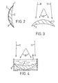
- Figure 2 is a schematic cross-section through a contact lens,
- Figures 3 and 4 schematically illustrate procedures for generating a hologram in a contact lens,
- Figure 5 schematically represents the passage of light through a bi-focal implant lens in accordance with the invention,
- Figure 6 is a schematic cross-section through an implant lens,
- Figure 7 schematically illustrates a procedure for generating a hologram in an implant lens, and
- Figure 8 is a graphical representation of efficiency of response against wavelength.
- Figure 1 schematically shows an artificial eye lens in the form of a contact lens 1 having a
posterior surface 2 of a curvature and shape which in known manner effectively fits the cornea and/or sclera of the wearer, and ananterior surface 3 of shape and curvature related to that of theposterior surface 2 and the refractive index of the material of the lens to provide suitable assistance and correction of the wearer's far vision. It will be understood that the lens is adapted to meet the particular requirements of the wearer so theanterior surface 3 may be of any desired curvature, e.g. spherical or toric, and the lens may be of any desired shape, e.g. with or without prism. For present purposes it is sufficient to consider the lens 1 as providing a basic refractive power appropriate for far vision of the wearer. Thus, light from a far object F is focussed by the contact lens 1 in conjunction with the wearer's natural eye lens 4 to a position R on the retina 5. The wearer can thus look at and see the far object F in focus. - However, since the wearer's vision is presbyopic, the basic lens 1, being adapted to far vision, and the natural eye lens 4 are of insufficient power to effect focussing on the retina of light from a near object N. As shown in broken line, light from such near object N would be focussed at a position R' spaced from and behind the retina 5. To overcome this the contact lens 1 has a transmission hologram, schematically represented at 6, which provides the lens with diffractive power, equivalent to lens power, such that light from the near object N which is diffracted is focussed by the hologram 6 (in conjunction with the basic power of the contact lens 1 and the eye lens 4) on to the retina 5. The wearer can thus look at and see the near object N in focus by means of the light which the hologram diffracts.
- As explained later, the hologram may operate on a wavelength selective basis (i.e. such that light within a particular wavelength band or bands is diffracted while light of other wavelengths is transmitted undeviated by the hologram), or on an amplitude selective basis (i.e. such that a proportion or amplitude portion of incident light of whatever wavelength is diffracted while the remainder is transmitted undeviated by the hologram), or on both a wavelength selective and an amplitude selective basis (i.e. such that the hologram operates preferentially over a particular wavelength band or bands but diffracts only a proportion of the incident light within that wavelength band or bands, the remainder of the incident light within that wavelength band or bands and light of other wavelengths being transmitted undeviated by the hologram).
- It will be understood that light from the near object N transmitted through the hologram undeviated thereby is focussed at the position R' behind the retina. However, since the position R' is spaced from the retina, the wearer's view of the near object N by way of light diffracted by the hologram is not unduly adversely affected by the undiffracted light. Conversely, when the wearer is looking at the far object F, light therefrom diffracted by the hologram becomes focussed (in conjunction with the action of the basic lens 1 and the natural eye lens 4) at a position R" spaced from and in front of the retina 5, as shown in broken line. The wearer's focussed view when looking at the far object F is therefore by way of light not diffracted by the hologram 6 and which is therefore transmitted through the hologram undeviated. Since position R" is spaced from the retina, this far view is not unduly adversely affected by light diffracted by the hologram.
- It will be appreciated that the hologram 6 should operate in a manner such as to provide a reasonable balance between the brightness of the far object F as viewed by way of the undiffracted light and the brightness of the near object N as viewed by way of the diffracted light.
- It will thus be seen that the lens 1 incorporating the hologram 6 provides a bi-focal effect, the hologram 6 constituting a holographic lens with diffractive power which adds to the basic refractive power of the lens 1 provided by its shape, curvature and material. Although there is in principle no particular limit to the additional power which could be provided by the hologram, preferably it has a power up to about four dioptres thereby giving a near-add value from 0 to +4 dioptres.
- As shown schematically in Figure 2, the contact lens 1 may have a
surface layer 7 of photographic material, such as dichromated gelatin, on itsanterior surface 3, and the hologram 6 may be formed in thatsurface layer 7. In use theanterior surface 3 is remote from the eye thus avoiding direct contact between thelayer 7 and the eye. Formation of the hologram in such surface layer is particularly suitable for a hard contact lens. Alternatively, however, the hologram 6 may be formed actually in the bulk material of the contact lens 1 if the material is suitable for hologram formation by means of an intense light source. Hologram formation in (or as mentioned later by surface relief on) the bulk material is appropriate for hard and soft contact lenses. - The hologram can be optically generated by active and reference beams, for example from a laser, directed at the contact lens effectively from conjugate point sources located so as to provide the required power in the resultant hologram. These light, and preferably laser, beams interfere within the photosensitive material either in the surface layer or the bulk of the contact lens. The interference fringes give areas of light and dark and the light areas, absorbed by the material, cause changes in its refractive index and/or absorption thus forming the hologram. Because of the shape and spacing of these fringes some of the light transmitted in use through the contact lens is diffracted as if the hologram was an additional lens. The power of this additional lens is determined by the origins of the two interfering light beams, and specifically by the vergence difference between them. If, for example, the reference beam is collimated, i.e. effectively originates from a point source located at infinity, it has a divergence of zero. If the active beam originates from the point source located at a finite distance from the contact lens, say 330mm, then it has a divergence of 3 dioptres. The power of the holographic lens is given by the vergence difference, 3 dioptres, between the two beams. Alternatively active and reference beams originating from point source locations at respective finite distances from the contact lens may be used so long . as the vergence difference between them equals the required holographic lens power, i.e. in the bi- focal context the required "near-add" value. It will be understood that the orginating locations of the active and reference beams may be optically generated, e.g. by use of mirrors or the like, rather than actual. Further, aberrations may be deliberately introduced so that the holographic lens is a better match to the requirements of the eye. These aberrations may be regular as in the case of spherical aberration, coma, astigmatism etc., or may be irregular as best suits the actual eye of a particular wearer.
- The bulk material of the contact lens may be tinted.
- The effective field of view of the holographic lens may be modified by the shape and depth of the interference fringes. No more than a few degrees is required to give good visual acuity over the fovea but this is not on the axis of the cornea and lens of the eye. The field of view must include the fovea either by increasing, i.e. making sufficently large, the overall field of view or by deliberately off-setting the active and reference beams to give an off-axis field of view for the hologram preferably with a shaped or ballasted contact lens.
- The active and reference beams may be directed at the contact lens from the front, as schematically shown in Figure 3 in which the beams are indicated at 10 and 11. In this case the refractive power of the anterior surface of the contact lens does not adversely affect the hologram generation and the vergence difference between the beams is maintained.
- The active and reference beams may alternatively be directed at the contact lens from the rear but in this case allowance should be made, or compensation introduced, for the refractive power of the posterior surface. In order effectively to remove the refractive power of the contact lens surface from the holographic generation procedure, the contact lens 1 can, as schematically shown in Figure 4, be immersed in a liquid 8 whose refractive index matches that of the contact lens material. The liquid may be contained in a bath vessel 9 of a size and shape such as to hold the immersed contact lens 1 in a fixed disposition while the active and reference beams are directed at it (as schematically represented at 10 and 11). Alternatively, the contact lens may be suspended in the liquid.
- The hologram 6 can advantageously be provided over the full area, or at least the full visually used area, of the contact lens 1, thus avoiding the need for distinct near and far zones.
- It will be appreciated that, although specifically described above by way of example in the bi-focal context, a contact lens having diffractive power can have other applications, for example to correct vision defects other than presbyopia. Further, a contact lens with diffractive power could be used to reduce chromatic aberration in normal vision (the normal eye usually involves about one dioptre of longitudinal colour) for example for sportsmen or soldiers.
- Figure 5 is similar to Figure 1 but schematically shows an artificial eye lens in the form of an implant lens which has been inserted within the eye in place of the natural eye lens (as distinct from the contact lens of Figure 1 which assists the natural eye lens).
- Thus Figure 5 schematically shows an implant lens 1' having a posterior surface 2' of given curvature and shape, and an anterior surface 3' of given shape and curvature related to that of the posterior surface 2' and the refractive index of the material of the lens and the aqueous and vitreous humours to provide suitable assistance and correction of the wearer's far vision. It will be understood that the lens is adapted to meet the particular requirements of the wearer so the posterior and anterior surfaces 2' and 3' may be of any desired curvature, e.g. spherical or toric, and the lens may be of any desired shape, e.g. with or without prism. For present purposes it is sufficient to consider the lens 1' as providing a basic refractive power appropriate for far vision of the wearer. Thus, light from a far object F is focussed by the implant lens 1' in conjunction with the wearer's cornea 4' to a position R on the retina 5'. The wearer can thus look at and see the far object F in focus.
- However, since the wearer's vision lacks accommodation, the basic lens 1', being adapted to far vision, and the cornea 4' are of insufficient power to effect focussing on the retina from a near object N. As shown in broken line, light from such near object N would be focussed at a position R' spaced from and behind the retina 5'. To overcome this the implant lens 1' has a transmission hologram, schematically represented at 6', which provides the lens with diffractive power, equivalent to lens power, such that light from the near object N which is diffracted is focussed by the hologram 6' (in conjunction with the basic power of the implant lens 1' and the cornea 4') on to the retina 5'. The wearer can thus look at and see the near object N in focus by means of the light diffracted by the hologram.
- As previously mentioned in relation to the hologram 6 of Figure 1, and as more fully explained later, the hologram 6' may operate on a wavelength selective basis, or an amplitude selective basis, or a combination of both.
- It will be understood that light which is not diffracted is transmitted through the hologram undeviated thereby. Such light from the near object N is focussed at the position R' behind the retina. However, since the position R' is spaced from the retina, the wearer's view of the near object N by way of the diffracted light is not unduly adversely affected by the undiffracted light. Conversely, when the wearer is looking at the far object F, light therefrom diffracted by the hologram becomes focussed (in conjunction with the action of the basic implant lens 1' and the cornea 4') at a position R" spaced from and in front of the retina 5', as shown in broken line. The wearer's focussed view when looking at the far object F is therefore by way of undiffracted light, and since position R" is spaced from the retina, this far view is not unduly adversely affected by the diffracted light.
- Again, there should be a reasonable balance between the brightness of the far object F as viewed by way of the undiffracted light and the brightness of the near object N as viewed by way of the diffracted light.
- It will thus be seen that the implant lens 1' incorporating the hologram 6' provides a bi-focal effect, the hologram constituting a holographic lens with diffractive power which adds to the basic power of the lens 1'. Although there is in principle no particular limit to the additional power which could be provided by the hologram, preferably it has a power up to about four dioptres thereby giving a near-add value from 0 to +4 dioptres.
- As shown schematically in Figure 6, the implant lens 1' may have a layer 7' of photographic material, such as dichromated gelatin, within its volume and the hologram 6' may be formed in that layer 7'. Alternatively, however, the hologram 6' may be formed actually in the bulk material of the implant lens 1' if the material is suitable, or as mentioned later by surface relief on the bulk material. The bulk material of the implant lens may be tinted.
- The hologram can be optically generated by active and reference beams, for example from a laser, directed at the implant lens effectively from conjugate point sources located so as to provide the required power in the resultant hologram in essentially the same manner as previously described in relation to the contact lens of Figures 1 to 4. These light, and preferably laser, beams interfere within the photosensitive material either in the layer 7' or the bulk of the implant lens.
- If the active and reference beams are deliberately off-set to give an off-axis field of view for the hologram the implant lens is preferably shaped or marked to facilitate surgical insertion in the appropriate orientation.
- In order effectively to reduce the refractive power of the implant lens surface for the holographic generation procedure, the implant lens 1' can, as schematically shown in Figure 7, be immersed in a liquid 8' whose refractive index matches that of the aqueous and vitreous humours. The liquid may be contained in a bath vessel 9' having a support (not shown) to hold the immersed implant lens 1' in a fixed disposition while the active and references beams are directed at it (as schematically represented at 10' and 11').
- Possible modes of operation of the hologram 6 or 6' will now be further explained with reference to Figure 8 which graphically represents efficiency against wavelength.
-
Curve 100 represents the normal human visual response extending from the commonly called blue end of the visible spectrum to the red end. -
Block 20 represents an idealistic transmission hologram which is wavelength selective with 100% efficiency. Thus, the hologram diffracts all the light over a selected wavelength band within the visible spectrum, but has no effect on light outside that selected wavelength band which is therefore transmitted through the hologram undeviated. The hologram may, for example, operate over a wavelength range covering between about one fifth and about one quarter of the visible spectrum, e.g. may be operative over a wavelength band of about 30 to 40 nanometres disposed around the green part of the visible spectrum. In thedrawing block 20 is shown as having vertical sides which provide a specific wavelength cut-off as between 100% efficiency diffraction and zero efficiency. Such cut-off is probably impossible to achieve in practice and usually there would be a fall-off in efficiency with changing wavelength. - A more normal practical transmission hologram is represented by
curve 30. This is shown as having its maximum efficiency, of about 60%, at a particular wavelength value and the efficiency falls off with change of wavelength from that value. Thus 60% of the light of the particular wavelength value is diffracted by the hologram while the other 40% is transmitted therethrough undeviated. The relative proportions of diffracted and undeviated light of other wavelengths vary as indicated by the curve. -
Line 40 represents an idealistic non-wavelength selective transmission hologram, i.e. which diffracts with the same efficiency (shown in the drawing as about 40%) for all wavelengths. Thus, for light of any wavelength transmitted through the hologram, 40% is diffracted while the other 60% passes undeviated. In practice such a hologram is very difficult to make. - Usually a broad band hologram has some variation of efficiency with wavelength. Typically this may be as represented by
curve 50 which shows the efficiency reducing to either side of a maximum value as the wavelength differs from that at which the maximum efficiency value applies. This hologram has diffractive power over all the visible spectrum (as has the idealistic non-wavelength selective hologram represented by line 40) but is of less than 100% efficiency. Thus, at all wavelengths within the visible spectrum, some light is diffracted on transmission through the hologram while other light passes through undeviated. - It will thus be understood that the hologram 6 or 6' may operate on a wavelength selective basis, as illustrated by
block 20 in Figure 8, or on an amplitude selective basis, as illustrated byline 40, or on a combined wavelength and amplitude selective basis as illustrated bycurve 30, and may operate over the full visible spectrum with different efficiencies, e.g. varying from about 20% to about 40%, at different wavelengths, as illustrated bycurve 50. - Referring again to Figures 1 and 5, it will be understood that wavelength selective operation means that light from the near object N within the wavelength band or bands over which the hologram operates is focussed on the retina, while light of other wavelengths is focussed at position R' and does not unduly adversely affect the view of the near object N. Light from the far object F within the wavelength band or bands over which the hologram operates is focussed at position R" and does not unduly adversely affect the view of the far object F by way of light of other wavelengths which is focussed on the retina. Amplitude selective operation means that a proportion of the light of a relevant wavelength from the near object N is focussed on the retina and a proportion is focussed at position R'. Similarly a proportion of the light of a relevant wavelength from the object F is focussed at position R" and a proportion is focussed on the retina. In the case where the hologram is operative (at less than 100% efficiency) at all wavelengths within visible spectrum, some light of any wavelength from the near object N is focussed on the retina and some at the position R', and some light of any wavelength from the far object F is focussed at R" and some on the retina. A combination of wavelength selection and amplitude selection means that some light from the near object N within the operative wavelength band or bands is focussed on the retina while some is focussed at position R' together with light of wavelengths outside the operative band or bands, and some light from the far object F within the operative wavelength band or bands is focussed at position R" while some is focussed on the retina together with light of wavelengths outside the operative band or bands. In all cases, the positions R' and R" are spaced from the retina so that light focussed at those positions is unfocussed at the retina and therefore does not unduly adversely affect the view by way of the light focussed on the retina.
- It will be appreciated that a transmission hologram may be provided effectively to add power to the basic power of a basic artificial eye lens, as described above, or could be provided to give power to a basically powerless (i.e. having basic refractive power of zero providing an infinity focus) basic artificial eye lens. Further, a transmission hologram of negative power could be provided e.g. effectively to substract power from the basic power of a basic artificial eye lens. Thus a bi-focal lens could have a basic power appropriate to near vision and an effectively negatively powered hologram for far vision. Yet further, if required a plurality of seprately generated holograms of different powers (for example operative over different wavelength bands) could be incorporated in a single artificial eye lens. Although as explained above the hologram can advantageously be provided over the full area, or the full visually used area, of the lens, it could, if desired, be provided over part only of that area (and separately generated holograms could be provided over different respective, possibly overlapping, part of the area).
- Further, instead of generating the hologram optically as described above, mechanical generation may be employed. Thus, the hologram may take the form of a surface relief hologram, and may be mechanically generated, for example during moulding of the basic artificial eye lens. Thus the appropriate mould surface may be adapted, e.g. may have suitable grooves or ridges, to provide the required relief in the lens surface to form the hologram. Further, a mechanically generated hologram could be made to lie within the lens by forming it in two parts and joining them.
- Yet further it will be appreciated that, although a transmission hologram is probably the most convenient way of imparting diffractive power to an artificial eye lens, it could be imparted in other ways such as forming a zone plate in analogous fashion to a diffraction grating.
Claims (12)
Applications Claiming Priority (6)
| Application Number | Priority Date | Filing Date | Title |
|---|---|---|---|
| GB8113149 | 1981-04-29 | ||
| GB8113149 | 1981-04-29 | ||
| GB8117709 | 1981-06-10 | ||
| GB8117709 | 1981-06-10 | ||
| GB8138854 | 1981-12-23 | ||
| GB8138854 | 1981-12-23 |
Publications (3)
| Publication Number | Publication Date |
|---|---|
| EP0064812A2 EP0064812A2 (en) | 1982-11-17 |
| EP0064812A3 EP0064812A3 (en) | 1983-03-30 |
| EP0064812B1 true EP0064812B1 (en) | 1985-08-14 |
Family
ID=27261172
Family Applications (1)
| Application Number | Title | Priority Date | Filing Date |
|---|---|---|---|
| EP82301793A Expired EP0064812B1 (en) | 1981-04-29 | 1982-04-05 | Artificial eye lenses |
Country Status (6)
| Country | Link |
|---|---|
| US (1) | US4642112A (en) |
| EP (1) | EP0064812B1 (en) |
| AU (1) | AU546822B2 (en) |
| DE (1) | DE3265356D1 (en) |
| GB (1) | GB2101764B (en) |
| IE (1) | IE53199B1 (en) |
Cited By (13)
| Publication number | Priority date | Publication date | Assignee | Title |
|---|---|---|---|---|
| US7713299B2 (en) | 2006-12-29 | 2010-05-11 | Abbott Medical Optics Inc. | Haptic for accommodating intraocular lens |
| US7763069B2 (en) | 2002-01-14 | 2010-07-27 | Abbott Medical Optics Inc. | Accommodating intraocular lens with outer support structure |
| US8034108B2 (en) | 2008-03-28 | 2011-10-11 | Abbott Medical Optics Inc. | Intraocular lens having a haptic that includes a cap |
| US8048156B2 (en) | 2006-12-29 | 2011-11-01 | Abbott Medical Optics Inc. | Multifocal accommodating intraocular lens |
| US8052752B2 (en) | 2002-10-25 | 2011-11-08 | Abbott Medical Optics Inc. | Capsular intraocular lens implant having a refractive liquid therein |
| US9198752B2 (en) | 2003-12-15 | 2015-12-01 | Abbott Medical Optics Inc. | Intraocular lens implant having posterior bendable optic |
| US11129707B2 (en) | 2015-08-12 | 2021-09-28 | Physiol S.A. | Trifocal intraocular lens with extended range of vision and correction of longitudinal chromatic aberration |
| US11529230B2 (en) | 2019-04-05 | 2022-12-20 | Amo Groningen B.V. | Systems and methods for correcting power of an intraocular lens using refractive index writing |
| US11564839B2 (en) | 2019-04-05 | 2023-01-31 | Amo Groningen B.V. | Systems and methods for vergence matching of an intraocular lens with refractive index writing |
| US11583388B2 (en) | 2019-04-05 | 2023-02-21 | Amo Groningen B.V. | Systems and methods for spectacle independence using refractive index writing with an intraocular lens |
| US11583389B2 (en) | 2019-04-05 | 2023-02-21 | Amo Groningen B.V. | Systems and methods for correcting photic phenomenon from an intraocular lens and using refractive index writing |
| US11678975B2 (en) | 2019-04-05 | 2023-06-20 | Amo Groningen B.V. | Systems and methods for treating ocular disease with an intraocular lens and refractive index writing |
| US11944574B2 (en) | 2019-04-05 | 2024-04-02 | Amo Groningen B.V. | Systems and methods for multiple layer intraocular lens and using refractive index writing |
Families Citing this family (146)
| Publication number | Priority date | Publication date | Assignee | Title |
|---|---|---|---|---|
| IE54650B1 (en) * | 1982-09-29 | 1989-12-20 | Pilkington Brothers Plc | An ophthalmic lens having diffractive power |
| GB2129157B (en) * | 1982-10-27 | 1986-02-05 | Pilkington Perkin Elmer Ltd | Bifocal contact lenses having defractive power |
| GB8404817D0 (en) * | 1984-02-23 | 1984-03-28 | Pilkington Perkin Elmer Ltd | Ophthalmic lenses |
| US4744647A (en) * | 1984-12-04 | 1988-05-17 | Lens Plus Co. | Semi-opaque corneal contact lens or intraoccular lens and method of formation |
| FR2588674B1 (en) * | 1985-10-11 | 1988-02-12 | Mutzel Francis | HOLOGRAPHIC GLASSES |
| US4752123A (en) * | 1985-11-19 | 1988-06-21 | University Optical Products Co. | Concentric bifocal contact lens with two distance power regions |
| US5121979A (en) * | 1986-05-14 | 1992-06-16 | Cohen Allen L | Diffractive multifocal optical device |
| US5144483A (en) * | 1986-05-14 | 1992-09-01 | Cohen Allen L | Diffractive multifocal optical device |
| US5366500A (en) * | 1986-06-05 | 1994-11-22 | Richard T. Schneider | One-piece bifocal intraocular lens construction |
| US5201762A (en) * | 1987-05-20 | 1993-04-13 | Hauber Frederick A | Intraocular archromatic lens |
| US5270744A (en) * | 1987-06-01 | 1993-12-14 | Valdemar Portney | Multifocal ophthalmic lens |
| EP0317685B1 (en) * | 1987-11-27 | 1994-11-30 | Research And Therapeutic Institute "Ophthalmos S.A." | Holographic lenses for ophthalmological use |
| US5089024A (en) * | 1988-04-19 | 1992-02-18 | Storz Instrument Company | Multi-focal intraocular lens |
| IE960172L (en) | 1988-07-20 | 1990-01-20 | Cohen Allen L | Multifocal ophthalmic lens |
| US4932966A (en) * | 1988-08-15 | 1990-06-12 | Storz Instrument Company | Accommodating intraocular lens |
| US4995714A (en) * | 1988-08-26 | 1991-02-26 | Cohen Allen L | Multifocal optical device with novel phase zone plate and method for making |
| US4909818A (en) * | 1988-11-16 | 1990-03-20 | Jones William F | System and process for making diffractive contact |
| GB8829819D0 (en) * | 1988-12-21 | 1989-02-15 | Freeman Michael H | Lenses and mirrors |
| FR2642855B1 (en) * | 1989-02-06 | 1991-05-17 | Essilor Int | OPTICAL LENS FOR THE CORRECTION OF ASTIGMATISM |
| US5073021A (en) * | 1989-03-17 | 1991-12-17 | Environmental Research Institute Of Michigan | Bifocal ophthalmic lens constructed from birefringent material |
| US5175651A (en) * | 1989-03-17 | 1992-12-29 | Environmental Research Institute Of Michigan | Multi-focus system for a low light level vision apparatus |
| FR2646930B1 (en) * | 1989-05-12 | 1993-04-09 | Essilor Int | PROCESS FOR PRODUCING A DIFFRACTIVE ELEMENT, USABLE IN PARTICULAR IN THE MANUFACTURE OF ARTIFICIAL OPTICAL LENSES, AND LENSES THUS OBTAINED |
| US5235441A (en) * | 1989-06-06 | 1993-08-10 | Spyros Georgaras | Holographic lenses |
| US5152788A (en) * | 1989-12-27 | 1992-10-06 | Minnesota Mining And Manufacturing Company | Multifocal diffractive ophthalmic lens and method of manufacture |
| US5135592A (en) * | 1989-12-27 | 1992-08-04 | Minnesota Mining And Manufacturing Company | Ultrasonically welded hydrogel ophthalmic lens |
| GB9008580D0 (en) * | 1990-04-17 | 1990-06-13 | Pilkington Diffractive Lenses | Manufacture of contact lenses |
| GB9008577D0 (en) * | 1990-04-17 | 1990-06-13 | Pilkington Diffractive Lenses | Rigid gas permeable lenses |
| US5096285A (en) * | 1990-05-14 | 1992-03-17 | Iolab Corporation | Multifocal multizone diffractive ophthalmic lenses |
| US5229797A (en) * | 1990-08-08 | 1993-07-20 | Minnesota Mining And Manufacturing Company | Multifocal diffractive ophthalmic lenses |
| US5256853A (en) * | 1991-07-31 | 1993-10-26 | Bausch & Lomb Incorporated | Method for shaping contact lens surfaces |
| US5748282A (en) * | 1993-01-27 | 1998-05-05 | Pilkington Barnes Hind, Inc. | Multifocal contact lens |
| US5895422A (en) * | 1993-06-17 | 1999-04-20 | Hauber; Frederick A. | Mixed optics intraocular achromatic lens |
| US5432623A (en) * | 1993-09-27 | 1995-07-11 | Egan; Michael S. | Optical lens incorporating an integral hologram |
| US5505964A (en) * | 1994-10-11 | 1996-04-09 | Allergan, Inc. | Liquid contact lens |
| US20020118457A1 (en) * | 2000-12-22 | 2002-08-29 | Dowski Edward Raymond | Wavefront coded imaging systems |
| US6911638B2 (en) | 1995-02-03 | 2005-06-28 | The Regents Of The University Of Colorado, A Body Corporate | Wavefront coding zoom lens imaging systems |
| US7218448B1 (en) * | 1997-03-17 | 2007-05-15 | The Regents Of The University Of Colorado | Extended depth of field optical systems |
| US20020195548A1 (en) * | 2001-06-06 | 2002-12-26 | Dowski Edward Raymond | Wavefront coding interference contrast imaging systems |
| RU2128355C1 (en) * | 1995-02-16 | 1999-03-27 | ТАСР Лтд. | Lenses for holographic spectacles |
| US20090069817A1 (en) * | 1995-10-20 | 2009-03-12 | Acufocus, Inc. | Intrastromal corneal modification |
| EP1044389A2 (en) * | 1997-12-29 | 2000-10-18 | Novartis AG | Actively controllable multifocal lens |
| BR9814551A (en) * | 1997-12-29 | 2000-10-10 | Novartis Ag | "composite holographic multifocal lens" |
| US6139146A (en) * | 1997-12-29 | 2000-10-31 | Novartis Ag | Programmable corrective lenses |
| US5997140A (en) * | 1997-12-29 | 1999-12-07 | Novartis Ag | Actively controllable multifocal lens |
| US6139147A (en) * | 1998-11-20 | 2000-10-31 | Novartis Ag | Actively controllable multifocal lens |
| IL123574A0 (en) | 1998-03-05 | 1998-10-30 | Holo Or Ltd | Progressive multifocal lens construction for eyeglasses |
| US6120148A (en) * | 1998-10-05 | 2000-09-19 | Bifocon Optics Gmbh | Diffractive lens |
| US6139145A (en) * | 1998-11-13 | 2000-10-31 | Israel; Henry M. | Ophthalmic optical element incorporating a holographic element and use of same in cases of central field loss |
| CA2351435A1 (en) * | 1998-12-16 | 2000-06-22 | William Rovani | Multifocal contact lens with aspheric surface |
| US6210005B1 (en) | 1999-02-04 | 2001-04-03 | Valdemar Portney | Multifocal ophthalmic lens with reduced halo size |
| WO2000052516A2 (en) * | 1999-03-01 | 2000-09-08 | Boston Innovative Optics, Inc. | System and method for increasing the depth of focus of the human eye |
| US20060238702A1 (en) | 1999-04-30 | 2006-10-26 | Advanced Medical Optics, Inc. | Ophthalmic lens combinations |
| US6250757B1 (en) | 1999-12-15 | 2001-06-26 | Johnson & Johnson Vision Products, Inc. | Hybrid refractive birefringent multifocal ophthalmic lenses |
| US7998412B2 (en) * | 2000-01-07 | 2011-08-16 | Smart Holograms Limited | Ophthalmic device comprising a holographic sensor |
| US6536898B1 (en) * | 2000-09-15 | 2003-03-25 | The Regents Of The University Of Colorado | Extended depth of field optics for human vision |
| US20020093701A1 (en) * | 2000-12-29 | 2002-07-18 | Xiaoxiao Zhang | Holographic multifocal lens |
| US6873733B2 (en) | 2001-01-19 | 2005-03-29 | The Regents Of The University Of Colorado | Combined wavefront coding and amplitude contrast imaging systems |
| US20120016349A1 (en) | 2001-01-29 | 2012-01-19 | Amo Development, Llc. | Hybrid ophthalmic interface apparatus and method of interfacing a surgical laser with an eye |
| SE0101293D0 (en) * | 2001-04-11 | 2001-04-11 | Pharmacia Groningen Bv | Technical field of the invention |
| US6842297B2 (en) | 2001-08-31 | 2005-01-11 | Cdm Optics, Inc. | Wavefront coding optics |
| US6851803B2 (en) * | 2002-10-24 | 2005-02-08 | C. Benjamin Wooley | Ophthalmic lenses with reduced chromatic blur |
| US7896916B2 (en) | 2002-11-29 | 2011-03-01 | Amo Groningen B.V. | Multifocal ophthalmic lens |
| SE0203564D0 (en) * | 2002-11-29 | 2002-11-29 | Pharmacia Groningen Bv | Multifocal opthalmic lens |
| US7662180B2 (en) | 2002-12-05 | 2010-02-16 | Abbott Medical Optics Inc. | Accommodating intraocular lens and method of manufacture thereof |
| US7036931B2 (en) * | 2003-01-29 | 2006-05-02 | Novartis Ag | Ophthalmic lenses |
| US7063422B2 (en) * | 2003-04-16 | 2006-06-20 | Novartis Ag | Multifocal ophthalmic lens |
| US7628810B2 (en) * | 2003-05-28 | 2009-12-08 | Acufocus, Inc. | Mask configured to maintain nutrient transport without producing visible diffraction patterns |
| US6951391B2 (en) * | 2003-06-16 | 2005-10-04 | Apollo Optical Systems Llc | Bifocal multiorder diffractive lenses for vision correction |
| US20050046794A1 (en) | 2003-06-17 | 2005-03-03 | Silvestrini Thomas A. | Method and apparatus for aligning a mask with the visual axis of an eye |
| EP1639398B9 (en) * | 2003-06-30 | 2012-02-22 | Werner Fiala | Intra-ocular lens or contact lens exhibiting large depth of focus |
| US7156516B2 (en) * | 2004-08-20 | 2007-01-02 | Apollo Optical Systems Llc | Diffractive lenses for vision correction |
| US7025456B2 (en) * | 2004-08-20 | 2006-04-11 | Apollo Optical Systems, Llc | Diffractive lenses for vision correction |
| JP2008517671A (en) * | 2004-10-22 | 2008-05-29 | アキュフォーカス・インコーポレーテッド | System and method for aligning an optical device with an eye axis |
| US7455404B2 (en) * | 2004-10-25 | 2008-11-25 | Advanced Medical Optics, Inc. | Ophthalmic lens with multiple phase plates |
| US7922326B2 (en) | 2005-10-25 | 2011-04-12 | Abbott Medical Optics Inc. | Ophthalmic lens with multiple phase plates |
| US8377123B2 (en) * | 2004-11-10 | 2013-02-19 | Visiogen, Inc. | Method of implanting an intraocular lens |
| US7491350B2 (en) * | 2004-12-01 | 2009-02-17 | Acufocus, Inc. | Method of making an ocular implant |
| US20060113054A1 (en) * | 2004-12-01 | 2006-06-01 | Silvestrini Thomas A | Method of making an ocular implant |
| US7976577B2 (en) * | 2005-04-14 | 2011-07-12 | Acufocus, Inc. | Corneal optic formed of degradation resistant polymer |
| US20060235428A1 (en) * | 2005-04-14 | 2006-10-19 | Silvestrini Thomas A | Ocular inlay with locator |
| US9636213B2 (en) | 2005-09-30 | 2017-05-02 | Abbott Medical Optics Inc. | Deformable intraocular lenses and lens systems |
| US20070168027A1 (en) * | 2006-01-13 | 2007-07-19 | Brady Daniel G | Accommodating diffractive intraocular lens |
| US8197539B2 (en) * | 2006-05-05 | 2012-06-12 | University Of Southern California | Intraocular camera for retinal prostheses |
| AR062067A1 (en) * | 2006-07-17 | 2008-10-15 | Novartis Ag | TORICAS CONTACT LENSES WITH CONTROLLED OPTICAL POWER PROFILE |
| US20080137030A1 (en) * | 2006-11-03 | 2008-06-12 | Hoffman William C | Optical devices with reduced chromatic aberration |
| US20080161914A1 (en) | 2006-12-29 | 2008-07-03 | Advanced Medical Optics, Inc. | Pre-stressed haptic for accommodating intraocular lens |
| US8740978B2 (en) * | 2007-08-27 | 2014-06-03 | Amo Regional Holdings | Intraocular lens having extended depth of focus |
| US8974526B2 (en) | 2007-08-27 | 2015-03-10 | Amo Groningen B.V. | Multizonal lens with extended depth of focus |
| US20090062911A1 (en) * | 2007-08-27 | 2009-03-05 | Amo Groningen Bv | Multizonal lens with extended depth of focus |
| US8747466B2 (en) * | 2007-08-27 | 2014-06-10 | Amo Groningen, B.V. | Intraocular lens having extended depth of focus |
| US9216080B2 (en) * | 2007-08-27 | 2015-12-22 | Amo Groningen B.V. | Toric lens with decreased sensitivity to cylinder power and rotation and method of using the same |
| US20090088840A1 (en) * | 2007-10-02 | 2009-04-02 | Simpson Michael J | Zonal diffractive multifocal intraocular lenses |
| US20090157179A1 (en) * | 2007-12-11 | 2009-06-18 | Pinto Candido D | Ophthalmic Lenses Providing an Extended Depth of Field |
| WO2009101202A1 (en) | 2008-02-15 | 2009-08-20 | Amo Regional Holdings | System, ophthalmic lens, and method for extending depth of focus |
| US8439498B2 (en) | 2008-02-21 | 2013-05-14 | Abbott Medical Optics Inc. | Toric intraocular lens with modified power characteristics |
| US8231219B2 (en) * | 2008-04-24 | 2012-07-31 | Amo Groningen B.V. | Diffractive lens exhibiting enhanced optical performance |
| US7871162B2 (en) * | 2008-04-24 | 2011-01-18 | Amo Groningen B.V. | Diffractive multifocal lens having radially varying light distribution |
| US8862447B2 (en) | 2010-04-30 | 2014-10-14 | Amo Groningen B.V. | Apparatus, system and method for predictive modeling to design, evaluate and optimize ophthalmic lenses |
| US20090306773A1 (en) * | 2008-06-04 | 2009-12-10 | Acufocus, Inc. | Opaque corneal insert for refractive correction |
| US8216307B2 (en) * | 2008-12-19 | 2012-07-10 | Novartis Ag | Radially segmented apodized diffractive multifocal design for ocular implant |
| NL2002540C2 (en) | 2009-02-17 | 2010-08-18 | Oculentis B V | Ophthalmic lens with optical sectors. |
| DE102009011838B4 (en) * | 2009-03-05 | 2017-08-31 | Fraunhofer-Gesellschaft zur Förderung der angewandten Forschung e.V. | Optical lens and manufacturing process |
| US8709079B2 (en) * | 2009-06-09 | 2014-04-29 | Novartis Ag | IOL with varying correction of chromatic aberration |
| US20100312336A1 (en) * | 2009-06-09 | 2010-12-09 | Xin Hong | Zonal diffractive multifocal intraocular lens with central monofocal diffractive region |
| CA2766655C (en) | 2009-06-26 | 2017-10-10 | Abbott Medical Optics Inc. | Accommodating intraocular lenses |
| US8128222B2 (en) * | 2009-07-27 | 2012-03-06 | Valdemar Portney | Multifocal diffractive contact lens with bi-sign surface shape |
| WO2011017322A1 (en) | 2009-08-03 | 2011-02-10 | Abbott Medical Optics Inc. | Intraocular lens for providing accomodative vision |
| US9492272B2 (en) | 2009-08-13 | 2016-11-15 | Acufocus, Inc. | Masked intraocular implants and lenses |
| NZ599397A (en) * | 2009-10-26 | 2014-09-26 | Novartis Ag | Phase-shifted center-distance diffractive design for ocular implant |
| USD656526S1 (en) | 2009-11-10 | 2012-03-27 | Acufocus, Inc. | Ocular mask |
| CN102892381A (en) * | 2009-12-18 | 2013-01-23 | Amo格罗宁根私人有限公司 | Single microstructure lens, systems and methods |
| US8331048B1 (en) | 2009-12-18 | 2012-12-11 | Bausch & Lomb Incorporated | Methods of designing lenses having selected depths of field |
| BE1019161A5 (en) * | 2010-01-26 | 2012-04-03 | Physiol | INTRAOCULAR LENS. |
| EP2646872A1 (en) | 2010-12-01 | 2013-10-09 | AMO Groningen B.V. | A multifocal lens having an optical add power progression, and a system and method of providing same |
| US9931200B2 (en) | 2010-12-17 | 2018-04-03 | Amo Groningen B.V. | Ophthalmic devices, systems, and methods for optimizing peripheral vision |
| US8894204B2 (en) | 2010-12-17 | 2014-11-25 | Abbott Medical Optics Inc. | Ophthalmic lens, systems and methods having at least one rotationally asymmetric diffractive structure |
| US9545303B2 (en) | 2011-12-02 | 2017-01-17 | Acufocus, Inc. | Ocular mask having selective spectral transmission |
| US9084674B2 (en) | 2012-05-02 | 2015-07-21 | Abbott Medical Optics Inc. | Intraocular lens with shape changing capability to provide enhanced accomodation and visual acuity |
| EP3824798A1 (en) | 2012-08-31 | 2021-05-26 | Amo Groningen B.V. | Multi-ring lens, systems and methods for extended depth of focus |
| WO2014087249A2 (en) | 2012-12-04 | 2014-06-12 | Amo Groningen B.V. | Lenses systems and methods for providing binocular customized treatments to correct presbyopia |
| US9561098B2 (en) | 2013-03-11 | 2017-02-07 | Abbott Medical Optics Inc. | Intraocular lens that matches an image surface to a retinal shape, and method of designing same |
| US9204962B2 (en) | 2013-03-13 | 2015-12-08 | Acufocus, Inc. | In situ adjustable optical mask |
| US9427922B2 (en) | 2013-03-14 | 2016-08-30 | Acufocus, Inc. | Process for manufacturing an intraocular lens with an embedded mask |
| EP3116442A1 (en) | 2014-03-10 | 2017-01-18 | Amo Groningen B.V. | Intraocular lens that improves overall vision where there is a local loss of retinal function |
| CN106714731B (en) | 2014-04-21 | 2019-09-27 | 阿莫格罗宁根私营有限公司 | Improve Ophthalmoligic instrument, the system and method for peripheral vision |
| WO2016040331A1 (en) | 2014-09-09 | 2016-03-17 | Staar Surgical Company | Ophthalmic implants with extended depth of field and enhanced distance visual acuity |
| EP3413839A1 (en) | 2016-02-09 | 2018-12-19 | AMO Groningen B.V. | Progressive power intraocular lens, and methods of use and manufacture |
| CN109070506B (en) | 2016-03-09 | 2021-06-29 | 斯塔尔外科有限公司 | Ocular implant with extended depth of field and enhanced distance vision |
| US10588738B2 (en) | 2016-03-11 | 2020-03-17 | Amo Groningen B.V. | Intraocular lenses that improve peripheral vision |
| CA3018549A1 (en) | 2016-03-23 | 2017-09-28 | Johnson & Johnson Surgical Vision, Inc. | Ophthalmic apparatus with corrective meridians having extended tolerance band |
| CA3018570A1 (en) | 2016-03-23 | 2017-09-28 | Johnson & Johnson Surgical Vision, Inc. | Ophthalmic apparatus with corrective meridians having extended tolerance band |
| CA3021474A1 (en) | 2016-04-19 | 2017-10-26 | Amo Groningen B.V. | Ophthalmic devices, system and methods that improve peripheral vision |
| EP3522771B1 (en) | 2016-10-25 | 2022-04-06 | Amo Groningen B.V. | Realistic eye models to design and evaluate intraocular lenses for a large field of view |
| AU2018235011A1 (en) | 2017-03-17 | 2019-10-24 | Amo Groningen B.V. | Diffractive intraocular lenses for extended range of vision |
| US10739227B2 (en) | 2017-03-23 | 2020-08-11 | Johnson & Johnson Surgical Vision, Inc. | Methods and systems for measuring image quality |
| US11523897B2 (en) | 2017-06-23 | 2022-12-13 | Amo Groningen B.V. | Intraocular lenses for presbyopia treatment |
| WO2019002384A1 (en) | 2017-06-28 | 2019-01-03 | Amo Groningen B.V. | Diffractive lenses and related intraocular lenses for presbyopia treatment |
| EP3639084A1 (en) | 2017-06-28 | 2020-04-22 | Amo Groningen B.V. | Extended range and related intraocular lenses for presbyopia treatment |
| US11327210B2 (en) | 2017-06-30 | 2022-05-10 | Amo Groningen B.V. | Non-repeating echelettes and related intraocular lenses for presbyopia treatment |
| WO2019048708A1 (en) | 2017-09-11 | 2019-03-14 | Amo Groningen B.V. | Methods and apparatuses to increase intraocular lenses positional stability |
| EP3687447A1 (en) | 2017-11-30 | 2020-08-05 | AMO Groningen B.V. | Intraocular lenses that improve post-surgical spectacle independent and methods of manufacturing thereof |
| BR112021002881A2 (en) | 2018-08-17 | 2021-05-11 | Staar Surgical Company | polymer composition exhibiting refractive index nanogradient |
| US11106056B2 (en) | 2019-03-28 | 2021-08-31 | Aizhong Zhang | Subzonal multifocal diffractive lens |
| AU2020416055A1 (en) | 2019-12-30 | 2022-08-25 | Amo Groningen B.V. | Lenses having diffractive profiles with irregular width for vision treatment |
| US11886046B2 (en) | 2019-12-30 | 2024-01-30 | Amo Groningen B.V. | Multi-region refractive lenses for vision treatment |
| US20230004023A1 (en) | 2021-06-14 | 2023-01-05 | Alcon Inc. | Diffractive contact lenses |
Family Cites Families (7)
| Publication number | Priority date | Publication date | Assignee | Title |
|---|---|---|---|---|
| US3339997A (en) * | 1962-07-30 | 1967-09-05 | Plastic Contact Lens Company | Bifocal ophthalmic lens having different color distance and near vision zones |
| US3794414A (en) * | 1972-05-12 | 1974-02-26 | Jessen Inc Wesley | Multiple focal contact lens |
| US4073579A (en) * | 1976-06-09 | 1978-02-14 | American Optical Corporation | Ophthalmic lens with locally variable index of refraction and method of making same |
| US4206518A (en) * | 1977-01-31 | 1980-06-10 | Fritz Jardon | Intraocular lens device |
| US4210391A (en) * | 1977-09-14 | 1980-07-01 | Cohen Allen L | Multifocal zone plate |
| US4377329A (en) * | 1980-02-26 | 1983-03-22 | Stanley Poler | Contact lens or the like |
| US4402579A (en) * | 1981-07-29 | 1983-09-06 | Lynell Medical Technology Inc. | Contact-lens construction |
-
1982
- 1982-04-05 GB GB08209995A patent/GB2101764B/en not_active Expired
- 1982-04-05 EP EP82301793A patent/EP0064812B1/en not_active Expired
- 1982-04-05 DE DE8282301793T patent/DE3265356D1/en not_active Expired
- 1982-04-14 US US06/368,362 patent/US4642112A/en not_active Expired - Lifetime
- 1982-04-14 AU AU82601/82A patent/AU546822B2/en not_active Ceased
- 1982-04-14 IE IE864/82A patent/IE53199B1/en not_active IP Right Cessation
Cited By (14)
| Publication number | Priority date | Publication date | Assignee | Title |
|---|---|---|---|---|
| US7763069B2 (en) | 2002-01-14 | 2010-07-27 | Abbott Medical Optics Inc. | Accommodating intraocular lens with outer support structure |
| US8052752B2 (en) | 2002-10-25 | 2011-11-08 | Abbott Medical Optics Inc. | Capsular intraocular lens implant having a refractive liquid therein |
| US9198752B2 (en) | 2003-12-15 | 2015-12-01 | Abbott Medical Optics Inc. | Intraocular lens implant having posterior bendable optic |
| US7713299B2 (en) | 2006-12-29 | 2010-05-11 | Abbott Medical Optics Inc. | Haptic for accommodating intraocular lens |
| US8048156B2 (en) | 2006-12-29 | 2011-11-01 | Abbott Medical Optics Inc. | Multifocal accommodating intraocular lens |
| US8034108B2 (en) | 2008-03-28 | 2011-10-11 | Abbott Medical Optics Inc. | Intraocular lens having a haptic that includes a cap |
| US11129707B2 (en) | 2015-08-12 | 2021-09-28 | Physiol S.A. | Trifocal intraocular lens with extended range of vision and correction of longitudinal chromatic aberration |
| US11529230B2 (en) | 2019-04-05 | 2022-12-20 | Amo Groningen B.V. | Systems and methods for correcting power of an intraocular lens using refractive index writing |
| US11564839B2 (en) | 2019-04-05 | 2023-01-31 | Amo Groningen B.V. | Systems and methods for vergence matching of an intraocular lens with refractive index writing |
| US11583388B2 (en) | 2019-04-05 | 2023-02-21 | Amo Groningen B.V. | Systems and methods for spectacle independence using refractive index writing with an intraocular lens |
| US11583389B2 (en) | 2019-04-05 | 2023-02-21 | Amo Groningen B.V. | Systems and methods for correcting photic phenomenon from an intraocular lens and using refractive index writing |
| US11678975B2 (en) | 2019-04-05 | 2023-06-20 | Amo Groningen B.V. | Systems and methods for treating ocular disease with an intraocular lens and refractive index writing |
| US11931296B2 (en) | 2019-04-05 | 2024-03-19 | Amo Groningen B.V. | Systems and methods for vergence matching of an intraocular lens with refractive index writing |
| US11944574B2 (en) | 2019-04-05 | 2024-04-02 | Amo Groningen B.V. | Systems and methods for multiple layer intraocular lens and using refractive index writing |
Also Published As
| Publication number | Publication date |
|---|---|
| AU8260182A (en) | 1982-11-04 |
| GB2101764B (en) | 1984-08-30 |
| EP0064812A2 (en) | 1982-11-17 |
| GB2101764A (en) | 1983-01-19 |
| AU546822B2 (en) | 1985-09-19 |
| IE820864L (en) | 1982-10-29 |
| DE3265356D1 (en) | 1985-09-19 |
| IE53199B1 (en) | 1988-08-31 |
| EP0064812A3 (en) | 1983-03-30 |
| US4642112A (en) | 1987-02-10 |
Similar Documents
| Publication | Publication Date | Title |
|---|---|---|
| EP0064812B1 (en) | Artificial eye lenses | |
| US4641934A (en) | Ophthalmic lens with diffractive power | |
| EP0375291B1 (en) | Lenses | |
| US6139147A (en) | Actively controllable multifocal lens | |
| US4655565A (en) | Ophthalmic lenses with diffractive power | |
| US6045578A (en) | Optical treatment method | |
| US5699142A (en) | Diffractive multifocal ophthalmic lens | |
| EP3435143B1 (en) | An ophthalmic multifocal diffractive lens | |
| KR102140425B1 (en) | Asymmetric lens design and method for preventing and/or slowing myopia progression | |
| US7455404B2 (en) | Ophthalmic lens with multiple phase plates | |
| KR20190136952A (en) | Ophthalmic lens comprising lenslets for preventing and/or slowing myopia progression | |
| US20110022170A1 (en) | Truncated diffractive intraocular lenses | |
| EP1348145A2 (en) | Holographic multifocal lens | |
| CA2741174A1 (en) | Multifocal intraocular lens | |
| US20180173009A1 (en) | Optical device for off-axis viewing | |
| US7338161B2 (en) | Optical accommodative compensation system | |
| WO1996016621A1 (en) | Optical treatment method | |
| RU2676945C1 (en) | Contact lens with improved visual characteristics and minimum halo when using pupil apodization | |
| US20230367139A1 (en) | Spectacle lens design, spectacle lens kit and method of manufacturing a spectacle lens | |
| CA2602507A1 (en) | Intraocular lens | |
| JPH0216890B2 (en) | ||
| AU695812B2 (en) | Optical treatment method | |
| EP4089473A1 (en) | Spectacle lens design, spectacle lens kit, method of manufacturing a spectacle lens and method of providing a spectacle lens design | |
| EP4174535A1 (en) | Intraocular lens | |
| CA3231167A1 (en) | Lenses having diffractive profiles with elevated surface roughness |
Legal Events
| Date | Code | Title | Description |
|---|---|---|---|
| PUAI | Public reference made under article 153(3) epc to a published international application that has entered the european phase |
Free format text: ORIGINAL CODE: 0009012 |
|
| AK | Designated contracting states |
Designated state(s): BE DE FR IT NL SE |
|
| PUAL | Search report despatched |
Free format text: ORIGINAL CODE: 0009013 |
|
| AK | Designated contracting states |
Designated state(s): BE DE FR IT NL SE |
|
| 17P | Request for examination filed |
Effective date: 19830704 |
|
| ITF | It: translation for a ep patent filed |
Owner name: BUGNION S.P.A. |
|
| GRAA | (expected) grant |
Free format text: ORIGINAL CODE: 0009210 |
|
| AK | Designated contracting states |
Designated state(s): BE DE FR IT NL SE |
|
| REF | Corresponds to: |
Ref document number: 3265356 Country of ref document: DE Date of ref document: 19850919 |
|
| ET | Fr: translation filed | ||
| BECH | Be: change of holder |
Free format text: 850814 *PILKINGTON BROTHERS P.L.C. |
|
| PLBE | No opposition filed within time limit |
Free format text: ORIGINAL CODE: 0009261 |
|
| STAA | Information on the status of an ep patent application or granted ep patent |
Free format text: STATUS: NO OPPOSITION FILED WITHIN TIME LIMIT |
|
| 26N | No opposition filed | ||
| REG | Reference to a national code |
Ref country code: FR Ref legal event code: TP |
|
| ITPR | It: changes in ownership of a european patent |
Owner name: CESSIONE;PILKINGTON BROTHERS PLC |
|
| NLS | Nl: assignments of ep-patents |
Owner name: PILKINGTON BROTHERS PLC TE ST. HELENS, GROOT-BRITT |
|
| ITTA | It: last paid annual fee | ||
| PGFP | Annual fee paid to national office [announced via postgrant information from national office to epo] |
Ref country code: SE Payment date: 19930319 Year of fee payment: 12 |
|
| PGFP | Annual fee paid to national office [announced via postgrant information from national office to epo] |
Ref country code: BE Payment date: 19930426 Year of fee payment: 12 |
|
| PGFP | Annual fee paid to national office [announced via postgrant information from national office to epo] |
Ref country code: NL Payment date: 19930430 Year of fee payment: 12 |
|
| PG25 | Lapsed in a contracting state [announced via postgrant information from national office to epo] |
Ref country code: SE Effective date: 19940406 |
|
| PG25 | Lapsed in a contracting state [announced via postgrant information from national office to epo] |
Ref country code: BE Effective date: 19940430 |
|
| BERE | Be: lapsed |
Owner name: PILKINGTON BROTHERS P.L.C. Effective date: 19940430 |
|
| PG25 | Lapsed in a contracting state [announced via postgrant information from national office to epo] |
Ref country code: NL Effective date: 19941101 |
|
| NLV4 | Nl: lapsed or anulled due to non-payment of the annual fee | ||
| EUG | Se: european patent has lapsed |
Ref document number: 82301793.4 Effective date: 19941110 |
|
| REG | Reference to a national code |
Ref country code: FR Ref legal event code: CD |
|
| PGFP | Annual fee paid to national office [announced via postgrant information from national office to epo] |
Ref country code: DE Payment date: 20010326 Year of fee payment: 20 |
|
| PGFP | Annual fee paid to national office [announced via postgrant information from national office to epo] |
Ref country code: FR Payment date: 20010409 Year of fee payment: 20 |