EP0063417A2 - Surgical evacuator - Google Patents
Surgical evacuator Download PDFInfo
- Publication number
- EP0063417A2 EP0063417A2 EP82301540A EP82301540A EP0063417A2 EP 0063417 A2 EP0063417 A2 EP 0063417A2 EP 82301540 A EP82301540 A EP 82301540A EP 82301540 A EP82301540 A EP 82301540A EP 0063417 A2 EP0063417 A2 EP 0063417A2
- Authority
- EP
- European Patent Office
- Prior art keywords
- end portion
- chamber
- evacuator
- proximal end
- piston rod
- Prior art date
- Legal status (The legal status is an assumption and is not a legal conclusion. Google has not performed a legal analysis and makes no representation as to the accuracy of the status listed.)
- Granted
Links
Images

Classifications
-
- A—HUMAN NECESSITIES
- A61—MEDICAL OR VETERINARY SCIENCE; HYGIENE
- A61M—DEVICES FOR INTRODUCING MEDIA INTO, OR ONTO, THE BODY; DEVICES FOR TRANSDUCING BODY MEDIA OR FOR TAKING MEDIA FROM THE BODY; DEVICES FOR PRODUCING OR ENDING SLEEP OR STUPOR
- A61M1/00—Suction or pumping devices for medical purposes; Devices for carrying-off, for treatment of, or for carrying-over, body-liquids; Drainage systems
- A61M1/71—Suction drainage systems
- A61M1/77—Suction-irrigation systems
- A61M1/772—Suction-irrigation systems operating alternately
-
- A—HUMAN NECESSITIES
- A61—MEDICAL OR VETERINARY SCIENCE; HYGIENE
- A61M—DEVICES FOR INTRODUCING MEDIA INTO, OR ONTO, THE BODY; DEVICES FOR TRANSDUCING BODY MEDIA OR FOR TAKING MEDIA FROM THE BODY; DEVICES FOR PRODUCING OR ENDING SLEEP OR STUPOR
- A61M1/00—Suction or pumping devices for medical purposes; Devices for carrying-off, for treatment of, or for carrying-over, body-liquids; Drainage systems
- A61M1/71—Suction drainage systems
- A61M1/74—Suction control
- A61M1/741—Suction control with means for varying suction manually
Definitions
- the cavity or sac may be a wound (caused by surgery or otherwise) which has been closed at its outermost region by suturation yet is required to heal from its innermost region in the direction towards the outermost region, or it may be a natural sac such as the bladder, a lung, the stomach or the like.
- the fluid to be drained may contain blood clots, mucus, or other matter less fluent than the remainder of the accumulate.
- the intake end of an ordinary drainage tube will frequently become occluded by the less fluent matter and it then becomes necessary to apply a substantially greater suction to the drainage tube in order to induce the obstructing matter-to enter the tube and proceed to waste by way thereof; moreoever, to facilitate evacuation, it is often desirable to irrigate the cavity or sac to be drained, with a saline or other solution to act as vehicle for the matters to be evacuated.
- the invention is applicable to a variety of drainage uses as indicated above, the need for an effective in-line evacuator arose in connection with the removal of blood clots from the bladder following prostatic or other surgery related to urological disorders. Because of this, the invention is described herein largely in terms of a urological in-line evacuator.
- the cystoflo drainage system comprises a catheter whereof the proximal end portion is entered into the bladder and the distal end portion opens to a urinary drainage bag or other receiver for the drained matter.
- the catheter of such a system includes a compressible rubber bulb which can be stocked with an irrigating liquid and delivered into the bladder by compression of the bulb. For suctional purposes, pressure on the bulb is relaxed so that of its own elasticity, the bulb tends to resume its unsqueezed globular shape.
- the prior system just discussed fails to develop a sufficiently strong suctional effect and frequently becomes quite ineffective in the presence of heavy bleeding involving extensive clotting.
- the object of the present invention is to overcome the indicated shortcomings in the provision of an in-line evacuator which:
- a duct tube has a proximal end portion 8 which can be introduced into the bladder indicated at 9.
- the proximal end portion 8 of the duct tube may conveniently be in one or more separable parts as will be understood.
- the duct tube has a distal end portion 10 from which evacuated liquid may be discharged in any convenient manner, for example, by being sent into a common urinary drainage receptacle 11.
- a cylindrical chamber 12 is connected in line with the duct portions 8 and 10, the chamber 12 having one end 13 open to the proximal end portion 8 and housing a piston plunger 14 which is reciprocable longitudinally of chamber 12.
- Plunger 14 is mounted on a tubular piston rod 15, the arrangement being such that the piston rod 15 has one end 16 open to that end of the cahmber 12 which is in communication with the proximal end portion 8 of the duct tube.
- the piston rod 15 slides in a bearing 17 and has its other or distal end 18 open to the distal end portion 10 of the duct tube.
- An irrigation inlet 19 opens to the chamber 12 and is connected by a supply tube 20 with a source of irrigation liquid indicated at 21.
- That portion of the proximal end 8 which is inserted into the bladder 9 by way of the urethra 22 may be of the common type known as a "Foley" balloon catheter as indicated as 23.
- the piston plunger 14 is located as shown in Figure 2 so that it closes the irrigation inlet 19.
- This inlet 19 could be closed by furnishing it with an on-off cock, but closure by way of the plunger 14 is preferred isnce the apparatus is thus less complicated.
- the evacuator (as shown in Figure 2) operates in simple drainage fashion like an ordinary catheter.
- inlet 19 and distal end portion 10 are closed, and plunger 14 retracted as indicated in Figure 3. This retraction is effected by finger pull on a handpiece 24 ( Figure 1) fixed on the piston rod 15.
- passages such as inlet 19, and also those at 25 and 26, are each provided with closure means, and these closure means may be hand operated on-off cocks.
- closure means may be hand operated on-off cocks.
- cocks are not preferred since there is a risk that they may be inadvertently left in "off” or closed position when not required; moreover, such cocks add unnecessary complication in the apparatus as a whole.
- each of the tubes 8, 10 and 20 is made of rubber, plastics or like flexible material so that the passage, or passages, concerned may be closed simply by hand or finger pressure sufficient to bend the tube or tubes to be closed so as to halt fluid flow through it or them.
- passage 19 it is effectively closed by the plunger 14 when the plunger 14 is in a position to do so as shown in Figure 2.
- passage 19 may be closed (as shown in Figures 3, 5, 6 and 7) by tube folding effected by way of the user's thumb pressure.
- This application of manual pressure may be facilitated (particularly in the case of passage 26 which would normally be closed by hand palm pressure while the fingers of the same hand are hooked about handpiece 24) by providing passage 26 with a flat, oblique end 27 against which the adjacent portion of tube 10 can be flatly pressed by the palm of the hand.
- the space between bearing 17 and handpiece 24 may be sealed by use of a conventional sylphon or concertina sleeve as indicated at 28 in Figure 1.
- the irrigation inlet 19 may be placed in the end wall 13 of the chamber 12 or otherwise as may be convenient provided it is closable (by plunger 14 or otherwise) when required.
- a compression loading spring may be applied between handpiece 24 and the adjacent end of the chamber 12 so that the evacuator may be used as a self-acting wound drain.
- Such a spring could be incorporated in, or constituted by, a concertina sleeve such as that indicated at 28; or, in the event of such a sleeve 28 not being incorporated, by an ordinary helical spring sleeved on piston rod 15 between the handpiece 24 and the adjacent end cover for chamber 12.
- the spring may be closely sleeved about rod 15 between bearing 17 and the mounting boss 29 of handpiece 24; that is, inside a sleeve such as 28.
Abstract
Description
- In the surgical treatment of patients (whether human or animal) it is frequently necessary to evacuate detrimental fluid accumulates from a cavity or sac in the patient's body. The cavity or sac may be a wound (caused by surgery or otherwise) which has been closed at its outermost region by suturation yet is required to heal from its innermost region in the direction towards the outermost region, or it may be a natural sac such as the bladder, a lung, the stomach or the like.
- In many cases nothing more than a simple drainage tube, duct or catheter is required, but in others the fluid to be drained may contain blood clots, mucus, or other matter less fluent than the remainder of the accumulate. When this is so, the intake end of an ordinary drainage tube will frequently become occluded by the less fluent matter and it then becomes necessary to apply a substantially greater suction to the drainage tube in order to induce the obstructing matter-to enter the tube and proceed to waste by way thereof; moreoever, to facilitate evacuation, it is often desirable to irrigate the cavity or sac to be drained, with a saline or other solution to act as vehicle for the matters to be evacuated.
- Although the invention is applicable to a variety of drainage uses as indicated above, the need for an effective in-line evacuator arose in connection with the removal of blood clots from the bladder following prostatic or other surgery related to urological disorders. Because of this, the invention is described herein largely in terms of a urological in-line evacuator.
- In the prior art, it has been common to use what is known as the cystoflo drainage system. This prior system comprises a catheter whereof the proximal end portion is entered into the bladder and the distal end portion opens to a urinary drainage bag or other receiver for the drained matter. The catheter of such a system includes a compressible rubber bulb which can be stocked with an irrigating liquid and delivered into the bladder by compression of the bulb. For suctional purposes, pressure on the bulb is relaxed so that of its own elasticity, the bulb tends to resume its unsqueezed globular shape. Experience has shown that the prior system just discussed fails to develop a sufficiently strong suctional effect and frequently becomes quite ineffective in the presence of heavy bleeding involving extensive clotting. When that happens, it is necessary to break the closed in-line system, thereby risking loss of its necessary sterility, and endeavour to evacuate the clots by use of other means. Even if this endeavour is successful it still involves another risk of sterility loss in re-establishing the broken in-line system.
- The object of the present invention is to overcome the indicated shortcomings in the provision of an in-line evacuator which:
- (1) provides a more-effectively powerful evacuation suction;
- (2) will avoid the necessity, to break the closed and sterile in-line system and thus reduce the likelihood of introducing infection; and
- (3) will remove need for catheter irrigation trays which are costly to set up and not always readily available when needed urgently.
- According to the present invention there is provided a surgical in-line evacuator characterized in that it comprises:
- (a) a duct tube having a proximal end portion which can be introduced into a bodily cavity or sac to be drained and a distal end portion leading to waste;
- (b) a cylindrical chamber to one end of which said proximal end portion is open;
- (c) a piston plunger reciprocable longitudinally of said chamber;
- (d) a tubular piston rod, upon one end of which said piston plunger is mounted, so that the bore of said piston rod opens to that end of said chamber to which said proximal end portion is open, and whereof the other end is open to said distal end portion;
- (e) an irrigation liquid inlet opening to said chamber adjacent the proximal end of said chamber, and
- (f) fluid-flow control means associated with each said proximal end portion, said distal end portion and said liquid inlet.
- An embodiment of the invention will now be described, by way of an example, with reference to the accompanying drawings, in which:-
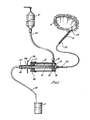
- Figure 1 is a purely diagrammatic representation of a urological in-line evacuator according to the present invention, and
- Figures 2 to 7 are schematic representations of the cylinder and plunger arrangement shown in Figure 1, showing the parts thereof disposed in accordance with several stages in usage.
- Referring to the drawings, a duct tube has a proximal end portion 8 which can be introduced into the bladder indicated at 9. The proximal end portion 8 of the duct tube may conveniently be in one or more separable parts as will be understood. The duct tube has a
distal end portion 10 from which evacuated liquid may be discharged in any convenient manner, for example, by being sent into a common urinary drainage receptacle 11. Acylindrical chamber 12 is connected in line with theduct portions 8 and 10, thechamber 12 having oneend 13 open to the proximal end portion 8 and housing apiston plunger 14 which is reciprocable longitudinally ofchamber 12.Plunger 14 is mounted on atubular piston rod 15, the arrangement being such that thepiston rod 15 has oneend 16 open to that end of thecahmber 12 which is in communication with the proximal end portion 8 of the duct tube. Thepiston rod 15 slides in abearing 17 and has its other ordistal end 18 open to thedistal end portion 10 of the duct tube. Anirrigation inlet 19 opens to thechamber 12 and is connected by asupply tube 20 with a source of irrigation liquid indicated at 21. - That portion of the proximal end 8 which is inserted into the bladder 9 by way of the
urethra 22 may be of the common type known as a "Foley" balloon catheter as indicated as 23. - When the evacuator is required to be used in the manner of a simple drainage tube, the
piston plunger 14 is located as shown in Figure 2 so that it closes theirrigation inlet 19. Thisinlet 19 could be closed by furnishing it with an on-off cock, but closure by way of theplunger 14 is preferred isnce the apparatus is thus less complicated. - The evacuator, (as shown in Figure 2) operates in simple drainage fashion like an ordinary catheter.
- In some cases it may be required to increase suctional force on portion 8 without irrigation being immediately necessary. If so,
inlet 19 anddistal end portion 10 are closed, and plunger 14 retracted as indicated in Figure 3. This retraction is effected by finger pull on a handpiece 24 (Figure 1) fixed on thepiston rod 15. - As previously indicated, passages such as
inlet 19, and also those at 25 and 26, are each provided with closure means, and these closure means may be hand operated on-off cocks. However, such cocks are not preferred since there is a risk that they may be inadvertently left in "off" or closed position when not required; moreover, such cocks add unnecessary complication in the apparatus as a whole. For preference, each of thetubes passages - In the case of
passage 19, it is effectively closed by theplunger 14 when theplunger 14 is in a position to do so as shown in Figure 2. When theplunger 14 is not in that position,passage 19 may be closed (as shown in Figures 3, 5, 6 and 7) by tube folding effected by way of the user's thumb pressure. - This application of manual pressure may be facilitated (particularly in the case of
passage 26 which would normally be closed by hand palm pressure while the fingers of the same hand are hooked about handpiece 24) by providingpassage 26 with a flat,oblique end 27 against which the adjacent portion oftube 10 can be flatly pressed by the palm of the hand. - When the bladder 9 is to be irrigated, cylinder 12 (see Figure 4) is charged with irrigation liquid by
closing passages 8 and 10, openingpassage 19 and retracting theplunger 14. To deliver the charge of liquid,passage 10 remains closed,passage 19 is closed, passage 8 opened and theplunger 14 advanced as shown in Figure 5. - If irrigation is followed by high suction evacuation, as indicated in Figure 6, the apparatus is conditioned and operated in the same way as explained in connection with Figure 3. Following such evacuation the contents of the
cylinder 14 are expelled, as shown in Figure 7, and the apparatus reverted to ordinary catheter drainage as shown in Figure 2. - As a further safeguard against loss of internal sterility, the space between bearing 17 and
handpiece 24 may be sealed by use of a conventional sylphon or concertina sleeve as indicated at 28 in Figure 1. - It will be appreciated that further modifications may be applied to the evacuator as described above. For example, the
irrigation inlet 19 may be placed in theend wall 13 of thechamber 12 or otherwise as may be convenient provided it is closable (byplunger 14 or otherwise) when required. Again, a compression loading spring may be applied betweenhandpiece 24 and the adjacent end of thechamber 12 so that the evacuator may be used as a self-acting wound drain. Such a spring could be incorporated in, or constituted by, a concertina sleeve such as that indicated at 28; or, in the event of such asleeve 28 not being incorporated, by an ordinary helical spring sleeved onpiston rod 15 between thehandpiece 24 and the adjacent end cover forchamber 12. If a concertina sleeve such as 28 is required to be employed with a spring as just discussed, the spring may be closely sleeved aboutrod 15 between bearing 17 and the mounting boss 29 ofhandpiece 24; that is, inside a sleeve such as 28. - It will be further appreciated that in some cases it may be desirable, for safety or other reasons, to lock the
plunger 14 in its closed position (as shown in Figure 1) so to ensure against unwanted discharge of liquid fromcontainer 21. This may be accomplished by use of a common grub screw able to bear uponrod 15 through bearing 17, or by a link pivoted oncylinder 12 and able to engagehandpiece 24, or otherwise.
Claims (5)
Priority Applications (1)
| Application Number | Priority Date | Filing Date | Title |
|---|---|---|---|
| AT82301540T ATE16455T1 (en) | 1981-04-02 | 1982-03-24 | SURGICAL DRAINAGE DEVICE. |
Applications Claiming Priority (3)
| Application Number | Priority Date | Filing Date | Title |
|---|---|---|---|
| AUPE827081 | 1981-04-02 | ||
| AU8270/81 | 1981-04-02 | ||
| CA000405699A CA1178509A (en) | 1981-04-02 | 1982-06-22 | Surgical 'in-line' evacuator |
Publications (3)
| Publication Number | Publication Date |
|---|---|
| EP0063417A2 true EP0063417A2 (en) | 1982-10-27 |
| EP0063417A3 EP0063417A3 (en) | 1983-02-02 |
| EP0063417B1 EP0063417B1 (en) | 1985-11-13 |
Family
ID=25642467
Family Applications (1)
| Application Number | Title | Priority Date | Filing Date |
|---|---|---|---|
| EP82301540A Expired EP0063417B1 (en) | 1981-04-02 | 1982-03-24 | Surgical evacuator |
Country Status (4)
| Country | Link |
|---|---|
| US (1) | US4457755A (en) |
| EP (1) | EP0063417B1 (en) |
| JP (1) | JPS57177758A (en) |
| CA (1) | CA1178509A (en) |
Cited By (1)
| Publication number | Priority date | Publication date | Assignee | Title |
|---|---|---|---|---|
| FR2581546A1 (en) * | 1985-05-10 | 1986-11-14 | Medicalex | Syringe/cannula for suction and injection |
Families Citing this family (36)
| Publication number | Priority date | Publication date | Assignee | Title |
|---|---|---|---|---|
| US4755167A (en) * | 1984-04-10 | 1988-07-05 | Research Corporation | In vivo method for distribution and stirring of therapeutic agents |
| DE3419613A1 (en) * | 1984-05-25 | 1985-11-28 | Kirchner & Wilhelm, 7000 Stuttgart | MOTHER MILK SUCTION DEVICE |
| US4723941A (en) * | 1985-09-06 | 1988-02-09 | Research Corporation | Pump for oscillating a fluid in vivo |
| JPH0817765B2 (en) * | 1987-07-24 | 1996-02-28 | 有限会社はやしべるぐ | Villi sample collecting endoscopy |
| US7198046B1 (en) * | 1991-11-14 | 2007-04-03 | Wake Forest University Health Sciences | Wound treatment employing reduced pressure |
| US5324266A (en) * | 1992-12-23 | 1994-06-28 | Abbott Laboratories | In-line sampling system incorporating an improved blood sampling device |
| US6458109B1 (en) | 1998-08-07 | 2002-10-01 | Hill-Rom Services, Inc. | Wound treatment apparatus |
| US6824533B2 (en) | 2000-11-29 | 2004-11-30 | Hill-Rom Services, Inc. | Wound treatment apparatus |
| US6764462B2 (en) | 2000-11-29 | 2004-07-20 | Hill-Rom Services Inc. | Wound treatment apparatus |
| ATE400315T1 (en) * | 1999-11-29 | 2008-07-15 | Hill Rom Services Inc | DEVICE FOR TREATING A WOUND |
| EP1294325B1 (en) | 2000-05-22 | 2008-09-10 | Arthur C. Coffey | Combination sis and vacuum bandage |
| US6855135B2 (en) * | 2000-11-29 | 2005-02-15 | Hill-Rom Services, Inc. | Vacuum therapy and cleansing dressing for wounds |
| US6685681B2 (en) | 2000-11-29 | 2004-02-03 | Hill-Rom Services, Inc. | Vacuum therapy and cleansing dressing for wounds |
| WO2002049692A2 (en) | 2000-12-19 | 2002-06-27 | Hill-Rom Services, Inc. | Low exposure waste disposal suction system |
| EP2204213B2 (en) | 2001-07-12 | 2020-04-01 | KCI Licensing, Inc. | Control of vacuum level rate of change |
| CA2462877A1 (en) * | 2001-10-11 | 2003-04-17 | Hill-Rom Services, Inc. | Waste container for negative pressure therapy |
| CA2468309A1 (en) | 2001-12-26 | 2003-07-17 | Robert Petrosenko | Wound vacuum therapy dressing kit |
| WO2003057070A2 (en) | 2001-12-26 | 2003-07-17 | Hill-Rom Services Inc. | Vented vacuum bandage and method |
| ATE387919T1 (en) | 2001-12-26 | 2008-03-15 | Hill Rom Services Inc | VACUUM BAND PACKAGING |
| EP1487389B1 (en) | 2002-02-28 | 2011-10-05 | KCI Medical Resources | External catheter access to vacuum bandage |
| CA2481016C (en) | 2002-04-10 | 2012-04-03 | Hill-Rom Services, Inc. | Access openings in vacuum bandage |
| AU2002359833A1 (en) | 2002-08-21 | 2004-03-11 | Hill-Rom Services, Inc. | Wound packing for preventing wound closure |
| US20040122434A1 (en) * | 2002-08-23 | 2004-06-24 | Argenta Louis C. | Bone treatment employing reduced pressure |
| US20040039391A1 (en) * | 2002-08-23 | 2004-02-26 | Argenta Louis C. | Bone treatment employing reduced pressure |
| US20050187532A1 (en) * | 2004-02-24 | 2005-08-25 | Medex, Inc. | Diaphragm-based reservoir for a closed blood sampling system |
| US7931651B2 (en) | 2006-11-17 | 2011-04-26 | Wake Lake University Health Sciences | External fixation assembly and method of use |
| US8377016B2 (en) * | 2007-01-10 | 2013-02-19 | Wake Forest University Health Sciences | Apparatus and method for wound treatment employing periodic sub-atmospheric pressure |
| US20080208171A1 (en) * | 2007-02-23 | 2008-08-28 | Argenta Louis C | Device and method for removing edema |
| US8267911B2 (en) * | 2007-06-08 | 2012-09-18 | Smiths Medical Asd, Inc. | Flow-through fluid reservoir |
| BRPI0817544A2 (en) | 2007-10-10 | 2017-05-02 | Univ Wake Forest Health Sciences | apparatus for treating damaged spinal cord tissue |
| WO2009089435A1 (en) | 2008-01-09 | 2009-07-16 | Wake Forest University Health Sciences | Device and method for treating central nervous system pathology |
| RU2544093C2 (en) | 2008-07-18 | 2015-03-10 | Уэйк Форест Юниверсити Хелс Сайенсиз | Device and method for cardiac tissue modulation by local application of pressure below atmospheric for minimising cell death and injury |
| US8740022B2 (en) * | 2012-02-15 | 2014-06-03 | Ecolab Usa Inc. | Volumetric metering device |
| CN107530072B (en) | 2015-01-20 | 2020-09-08 | 斯派创脊椎Ip控股有限责任公司 | Surgical drainage system and method of use |
| US10583228B2 (en) | 2015-07-28 | 2020-03-10 | J&M Shuler Medical, Inc. | Sub-atmospheric wound therapy systems and methods |
| US11160917B2 (en) | 2020-01-22 | 2021-11-02 | J&M Shuler Medical Inc. | Negative pressure wound therapy barrier |
Citations (3)
| Publication number | Priority date | Publication date | Assignee | Title |
|---|---|---|---|---|
| GB125050A (en) * | 1918-04-03 | 1919-08-06 | Jean Etienne Larche | A Pump with Permeable Piston for Medical Purposes. |
| CH117446A (en) * | 1926-01-13 | 1926-11-01 | Albert Furrer | Flushing device, in particular for hygienic body care. |
| FR1270595A (en) * | 1960-07-19 | 1961-09-01 | Duffaud & Cie | Further development of multiple-way syringes |
Family Cites Families (4)
| Publication number | Priority date | Publication date | Assignee | Title |
|---|---|---|---|---|
| US1410530A (en) * | 1919-03-29 | 1922-03-21 | Larche Jean Etienne | Pump with permeable piston for multiple purposes |
| US2923296A (en) * | 1955-06-27 | 1960-02-02 | Baxter Don Inc | Enema container |
| NL262824A (en) * | 1961-03-21 | |||
| US3703899A (en) * | 1971-01-28 | 1972-11-28 | Teodora A Calinog | Surgical drainage instrument |
-
1982
- 1982-03-18 US US06/359,419 patent/US4457755A/en not_active Expired - Lifetime
- 1982-03-24 EP EP82301540A patent/EP0063417B1/en not_active Expired
- 1982-04-01 JP JP57054728A patent/JPS57177758A/en active Granted
- 1982-06-22 CA CA000405699A patent/CA1178509A/en not_active Expired
Patent Citations (3)
| Publication number | Priority date | Publication date | Assignee | Title |
|---|---|---|---|---|
| GB125050A (en) * | 1918-04-03 | 1919-08-06 | Jean Etienne Larche | A Pump with Permeable Piston for Medical Purposes. |
| CH117446A (en) * | 1926-01-13 | 1926-11-01 | Albert Furrer | Flushing device, in particular for hygienic body care. |
| FR1270595A (en) * | 1960-07-19 | 1961-09-01 | Duffaud & Cie | Further development of multiple-way syringes |
Cited By (1)
| Publication number | Priority date | Publication date | Assignee | Title |
|---|---|---|---|---|
| FR2581546A1 (en) * | 1985-05-10 | 1986-11-14 | Medicalex | Syringe/cannula for suction and injection |
Also Published As
| Publication number | Publication date |
|---|---|
| EP0063417A3 (en) | 1983-02-02 |
| US4457755A (en) | 1984-07-03 |
| CA1178509A (en) | 1984-11-27 |
| EP0063417B1 (en) | 1985-11-13 |
| JPS57177758A (en) | 1982-11-01 |
| JPS636223B2 (en) | 1988-02-08 |
Similar Documents
| Publication | Publication Date | Title |
|---|---|---|
| EP0063417B1 (en) | Surgical evacuator | |
| US11806489B2 (en) | Balloon catheter inflation apparatus and methods | |
| EP1572286B1 (en) | Endoscopic wound care treatment system | |
| US5230704A (en) | Suction/irrigation instrument having reusable handle with disposable fluid path | |
| US7270647B2 (en) | Apparatus for vacuum-assisted irrigation and drainage of a body cavity | |
| US5472416A (en) | Tumescent lipoplastic method and apparatus | |
| US4792327A (en) | Lipectomy cannula | |
| EP0264419B1 (en) | Ophthalmic aspirating/irrigating device | |
| CA2108709A1 (en) | Suction systems | |
| US9878145B2 (en) | Apparatus including a conduit clamping device | |
| US4263911A (en) | Hand actuated medical suction apparatus | |
| CN106552312A (en) | Negative-pressure irrigation device | |
| US5545176A (en) | Wound dilatation device | |
| US8858504B2 (en) | Haemostatic valve assembly | |
| CN112336414A (en) | Thrombectomy with venturi aspiration | |
| AU6480498A (en) | Stomach Suction Pump Connector Valve | |
| US5447493A (en) | Tumescent lipoplastic apparatus | |
| GB2125296A (en) | Wound irrigator | |
| US20110306941A1 (en) | Portable Lavage Apparatus | |
| EP3031412B1 (en) | Catheter with a collection chamber | |
| CN204468952U (en) | Operation negative pressure suction device suction catheter | |
| CN219847579U (en) | Biliary tract drainage device after intrahepatic duct calculus excision | |
| EP1996250A1 (en) | Apparatus for removal of accumulation of fluid or air below skin level | |
| AU2017223498A1 (en) | Yankauer suction system and related methods with clog removal functionality | |
| WO2024030558A1 (en) | Portable evacuation system |
Legal Events
| Date | Code | Title | Description |
|---|---|---|---|
| PUAI | Public reference made under article 153(3) epc to a published international application that has entered the european phase |
Free format text: ORIGINAL CODE: 0009012 |
|
| AK | Designated contracting states |
Designated state(s): AT BE CH DE FR GB IT LU NL SE |
|
| PUAL | Search report despatched |
Free format text: ORIGINAL CODE: 0009013 |
|
| AK | Designated contracting states |
Designated state(s): AT BE CH DE FR GB IT LI LU NL SE |
|
| 17P | Request for examination filed |
Effective date: 19830308 |
|
| ITF | It: translation for a ep patent filed |
Owner name: MARIETTI E GISLON S.R.L. |
|
| GRAA | (expected) grant |
Free format text: ORIGINAL CODE: 0009210 |
|
| AK | Designated contracting states |
Designated state(s): AT BE CH DE FR GB IT LI LU NL SE |
|
| REF | Corresponds to: |
Ref document number: 16455 Country of ref document: AT Date of ref document: 19851115 Kind code of ref document: T |
|
| REF | Corresponds to: |
Ref document number: 3267360 Country of ref document: DE Date of ref document: 19851219 |
|
| ET | Fr: translation filed | ||
| PLBE | No opposition filed within time limit |
Free format text: ORIGINAL CODE: 0009261 |
|
| STAA | Information on the status of an ep patent application or granted ep patent |
Free format text: STATUS: NO OPPOSITION FILED WITHIN TIME LIMIT |
|
| 26N | No opposition filed | ||
| ITTA | It: last paid annual fee | ||
| EPTA | Lu: last paid annual fee | ||
| EAL | Se: european patent in force in sweden |
Ref document number: 82301540.9 |
|
| PGFP | Annual fee paid to national office [announced via postgrant information from national office to epo] |
Ref country code: BE Payment date: 19980126 Year of fee payment: 17 |
|
| PGFP | Annual fee paid to national office [announced via postgrant information from national office to epo] |
Ref country code: FR Payment date: 19980130 Year of fee payment: 17 |
|
| PGFP | Annual fee paid to national office [announced via postgrant information from national office to epo] |
Ref country code: SE Payment date: 19980317 Year of fee payment: 17 |
|
| PGFP | Annual fee paid to national office [announced via postgrant information from national office to epo] |
Ref country code: GB Payment date: 19980323 Year of fee payment: 17 Ref country code: LU Payment date: 19980323 Year of fee payment: 17 |
|
| PGFP | Annual fee paid to national office [announced via postgrant information from national office to epo] |
Ref country code: AT Payment date: 19980331 Year of fee payment: 17 Ref country code: NL Payment date: 19980331 Year of fee payment: 17 |
|
| PGFP | Annual fee paid to national office [announced via postgrant information from national office to epo] |
Ref country code: DE Payment date: 19980424 Year of fee payment: 17 |
|
| PGFP | Annual fee paid to national office [announced via postgrant information from national office to epo] |
Ref country code: CH Payment date: 19980608 Year of fee payment: 17 |
|
| PG25 | Lapsed in a contracting state [announced via postgrant information from national office to epo] |
Ref country code: GB Free format text: LAPSE BECAUSE OF NON-PAYMENT OF DUE FEES Effective date: 19990324 Ref country code: AT Free format text: LAPSE BECAUSE OF NON-PAYMENT OF DUE FEES Effective date: 19990324 Ref country code: LU Free format text: LAPSE BECAUSE OF EXPIRATION OF PROTECTION Effective date: 19990324 |
|
| PG25 | Lapsed in a contracting state [announced via postgrant information from national office to epo] |
Ref country code: SE Free format text: LAPSE BECAUSE OF NON-PAYMENT OF DUE FEES Effective date: 19990325 |
|
| PG25 | Lapsed in a contracting state [announced via postgrant information from national office to epo] |
Ref country code: BE Free format text: LAPSE BECAUSE OF NON-PAYMENT OF DUE FEES Effective date: 19990331 Ref country code: CH Free format text: LAPSE BECAUSE OF NON-PAYMENT OF DUE FEES Effective date: 19990331 Ref country code: LI Free format text: LAPSE BECAUSE OF NON-PAYMENT OF DUE FEES Effective date: 19990331 |
|
| BERE | Be: lapsed |
Owner name: WILSON JOHN DAVID Effective date: 19990331 |
|
| PG25 | Lapsed in a contracting state [announced via postgrant information from national office to epo] |
Ref country code: NL Free format text: LAPSE BECAUSE OF NON-PAYMENT OF DUE FEES Effective date: 19991001 |
|
| EUG | Se: european patent has lapsed |
Ref document number: 82301540.9 |
|
| REG | Reference to a national code |
Ref country code: CH Ref legal event code: PL |
|
| GBPC | Gb: european patent ceased through non-payment of renewal fee |
Effective date: 19990324 |
|
| PG25 | Lapsed in a contracting state [announced via postgrant information from national office to epo] |
Ref country code: FR Free format text: LAPSE BECAUSE OF NON-PAYMENT OF DUE FEES Effective date: 19991130 |
|
| NLV4 | Nl: lapsed or anulled due to non-payment of the annual fee |
Effective date: 19991001 |
|
| EUG | Se: european patent has lapsed |
Ref document number: 82301540.9 |
|
| REG | Reference to a national code |
Ref country code: FR Ref legal event code: ST |
|
| PG25 | Lapsed in a contracting state [announced via postgrant information from national office to epo] |
Ref country code: DE Free format text: LAPSE BECAUSE OF NON-PAYMENT OF DUE FEES Effective date: 20000101 |