EP0062889A1 - Liquid droplets recording device - Google Patents
Liquid droplets recording device Download PDFInfo
- Publication number
- EP0062889A1 EP0062889A1 EP82102956A EP82102956A EP0062889A1 EP 0062889 A1 EP0062889 A1 EP 0062889A1 EP 82102956 A EP82102956 A EP 82102956A EP 82102956 A EP82102956 A EP 82102956A EP 0062889 A1 EP0062889 A1 EP 0062889A1
- Authority
- EP
- European Patent Office
- Prior art keywords
- teeth
- comb
- writing
- transducers
- liquid droplets
- Prior art date
- Legal status (The legal status is an assumption and is not a legal conclusion. Google has not performed a legal analysis and makes no representation as to the accuracy of the status listed.)
- Granted
Links
Images
Classifications
-
- B—PERFORMING OPERATIONS; TRANSPORTING
- B41—PRINTING; LINING MACHINES; TYPEWRITERS; STAMPS
- B41J—TYPEWRITERS; SELECTIVE PRINTING MECHANISMS, i.e. MECHANISMS PRINTING OTHERWISE THAN FROM A FORME; CORRECTION OF TYPOGRAPHICAL ERRORS
- B41J2/00—Typewriters or selective printing mechanisms characterised by the printing or marking process for which they are designed
- B41J2/005—Typewriters or selective printing mechanisms characterised by the printing or marking process for which they are designed characterised by bringing liquid or particles selectively into contact with a printing material
- B41J2/01—Ink jet
- B41J2/135—Nozzles
- B41J2/145—Arrangement thereof
- B41J2/155—Arrangement thereof for line printing
-
- B—PERFORMING OPERATIONS; TRANSPORTING
- B41—PRINTING; LINING MACHINES; TYPEWRITERS; STAMPS
- B41J—TYPEWRITERS; SELECTIVE PRINTING MECHANISMS, i.e. MECHANISMS PRINTING OTHERWISE THAN FROM A FORME; CORRECTION OF TYPOGRAPHICAL ERRORS
- B41J2/00—Typewriters or selective printing mechanisms characterised by the printing or marking process for which they are designed
- B41J2/005—Typewriters or selective printing mechanisms characterised by the printing or marking process for which they are designed characterised by bringing liquid or particles selectively into contact with a printing material
- B41J2/01—Ink jet
- B41J2/135—Nozzles
- B41J2/14—Structure thereof only for on-demand ink jet heads
- B41J2/14201—Structure of print heads with piezoelectric elements
- B41J2/14282—Structure of print heads with piezoelectric elements of cantilever type
-
- B—PERFORMING OPERATIONS; TRANSPORTING
- B41—PRINTING; LINING MACHINES; TYPEWRITERS; STAMPS
- B41J—TYPEWRITERS; SELECTIVE PRINTING MECHANISMS, i.e. MECHANISMS PRINTING OTHERWISE THAN FROM A FORME; CORRECTION OF TYPOGRAPHICAL ERRORS
- B41J2/00—Typewriters or selective printing mechanisms characterised by the printing or marking process for which they are designed
- B41J2/005—Typewriters or selective printing mechanisms characterised by the printing or marking process for which they are designed characterised by bringing liquid or particles selectively into contact with a printing material
- B41J2/01—Ink jet
- B41J2/135—Nozzles
- B41J2/14—Structure thereof only for on-demand ink jet heads
- B41J2002/14387—Front shooter
Definitions
- the invention relates to an operating with liquid droplets writing instrument pointwise recording of analogue curves or alphanumerical characters and of images, for writing of the individual dots in rows arranged nozzles are provided, prior to their entry openings so contacted piezoelectric transducers are arranged such that changes in s-in electrical Spannun g ejected at the contacting writing fluid from the nozzle and onto one in front of the outlet. Opening of the nozzles arranged recording medium is applied, the individual transducers being formed by the teeth of a comb-like piezo plate and the plate material itself being bilaminarly formed from piezoceramic and a carrier material.
- Such a writing instrument in which the plate material consists of piezoceramic and metal, is known from DE-OS 25 27 647. Because of the shape of the piezo plate and The plate material creates a mechanical coupling between the teeth via the common ridge of the teeth. If a tooth is excited by a tension in such a way that it bends, the result is that the neighboring teeth also bend, although not equally strongly, with a certain delay. Due to the mechanical coupling, the more distant teeth are also affected; the excitation of these teeth decreases with the distance to the excited tooth. In the known writing instrument, the comb web of the piezo plate is attached to a carrier, so that this part of the piezo plate cannot be bent. If the comb web of the piezo plate to be clamped to the holder of the writing instrument is slightly bent, the plate can easily break when clamped.
- each tooth must be in the rest position before it is actuated. If two adjacent teeth are to be actuated one after the other, the first actuated tooth should not cause the adjacent tooth to vibrate. If this is done, the time interval between the actuation pulses must be made so long that the vibration of the adjacent tooth has subsided. The result is a sharp drop in the maximum write speed.
- the invention has for its object to provide a writing instrument of the type mentioned, in which the mechanical coupling between the teeth of the piezo plate is reduced so that the transmission of the coupling forces from an activated tooth to the adjacent teeth is eliminated.
- the piezo plate should be so flexible that it breaks when the comb is clamped back is avoided.
- this object is achieved in that, in order to reduce the mechanical coupling between the teeth, the ceramic material is removed via the comb web common to all teeth. Because only the carrier material connects the teeth to one another, the mechanical coupling between the teeth is reduced in such a way that when a tooth is activated, the adjacent teeth are not influenced. Furthermore, the piezo plate is now so flexible that no breakage can occur in the plate when clamping the comb back. "
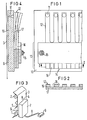
- FIG. 3 shows the outer basic structure of a writing instrument.
- the record carrier 3 z. B. normal registration paper, drawn in the direction of arrow 4 over a spacer 5 on the side 6 of the housing 7.
- the connecting line 8 is guided, which at its free end with a plug 9 for connection to a Darge is provided control unit which supplies the control signals for recording the desired courses, characters or images.
- the side 6 is the side of a carrier 10 which has a number of nozzles 11 arranged in a row next to one another.
- rod-shaped transducers 12 made of piezoelectric material are present in the housing, which are contacted and arranged in such a way that they spray writing fluid in the form of a droplet from the nozzle 11 when appropriately controlled electrically.
- the piezo comb 14 consisting of the transducers 12 and the comb back 13 is arranged parallel to the plane of the carrier 10.
- FIG. 4 shows that the comb-like piezo plate is bilaminar and is formed from a piezoceramic layer 16 and a metal layer 17.
- the free end area of the individual transducers 12 is located in front of the individual nozzles 11 of the row of nozzles.
- the comb back 13 is screwed to the carrier 10 receiving the row of nozzles with a fastening screw set 15.
- each nozzle 11 or tooth 12 is about 250 microns.
- ceramic or glass e.g. As aluminum oxide or silicon may be provided.
Abstract
Bei einem mit Flüssigkeitströpfchen arbeitenden Schreibgerät zur punktweisen Aufzeichnung von Zeichen oder Bildern sind zum Schreiben der einzelnen Punkte reihenweise angeordnete Düsen vorhanden, denen eine gleiche Anzahl piezoelektrischer Wandler zugeordnet ist. Die einzelnen Wandler werden durch die Zähne einer kammartigen Piezoplatte, die bilaminar aus Piezokeramik und einem Tragermaterial gebildet ist, geformt. Um die mechanische Kopplung zwischen den Zähnen so zu verringern, dass die Übertragung von Kopplungskräften von einem aktivierten Zahn auf die benachbarten Zähne beseitigt werden, ist erfindungsgemäss vorgesehen, dass zwischen den Zähnen (12) über den allen Zähnen (12) gemeinsamen Kammsteg (13) das Keramikmaterial (16) in der Verlängerung der Zahnzwischenräume (18) auch auf dem Kammsteg (13) entfernt ist.In a writing device working with liquid droplets for the point-by-point recording of characters or images, there are nozzles arranged in rows for writing the individual points, to which an equal number of piezoelectric transducers is assigned. The individual transducers are formed by the teeth of a comb-like piezoplate, which is bilaminarly formed from piezoceramic and a carrier material. In order to reduce the mechanical coupling between the teeth in such a way that the transmission of coupling forces from an activated tooth to the adjacent teeth is eliminated, the invention provides that between the teeth (12) over the comb web (13) common to all teeth (12). the ceramic material (16) in the extension of the interdental spaces (18) is also removed on the comb web (13).
Description
Die Erfindung betrifft ein mit Flüssigkeitströpfchen arbeitendes Schreibgerät zur punktweisen Aufzeichnung analoger Verläufe oder alphanumerischer Zeichen sowie von Bildern, wobei zum Schreiben der einzelnen Punkte reihenweise angeordnete Düsen vorhanden sind, vor deren Eintrittsöffnungen derart kontaktierte piezoelektrische Wandler angeordnet sind, dass bei elektrischen Spannungs-änderungen an der Kontaktierung Schreibflüssigkeit aus der Düse herausgestossen und auf einen vor der Austritts-. öffnung der Düsen angeordnetem Aufzeichnungsträger aufgebracht wird, wobei die einzelnen Wandler durch die Zähne einer kammartigen Piezoplatte geformt werden und das Plattenmaterial selbst bilaminar aus Piezokeramik und einem Trägermaterial gebildet ist.The invention relates to an operating with liquid droplets writing instrument pointwise recording of analogue curves or alphanumerical characters and of images, for writing of the individual dots in rows arranged nozzles are provided, prior to their entry openings so contacted piezoelectric transducers are arranged such that changes in s-in electrical Spannun g ejected at the contacting writing fluid from the nozzle and onto one in front of the outlet. Opening of the nozzles arranged recording medium is applied, the individual transducers being formed by the teeth of a comb-like piezo plate and the plate material itself being bilaminarly formed from piezoceramic and a carrier material.
Ein solches Schreibgerät, bei dem das Plattenmaterial aus Piezokeramik und Metall besteht, ist durch die DE-OS 25 27 647 bekannt. Wegen der Form der Piezoplatte und des Plattenmaterials entsteht über den gemeinsamen Kammsteg der Zähne eine mechanische Kopplung zwischen diesen. Wenn ein Zahn durch eine Spannung derart angeregt wird, dass er sich biegt, hat das zur Folge, dass die benachbarten Zähne sich mit einer gewissen Verzögerung ebenfalls, wenn auch nicht gleich stark, biegen. Aufgrund der mechanischen Kopplung werden auch die weiter entfernten Zähne beeinflusst; die Anregung dieser Zähne nimmt aber mit dem Abstand zum angerecten Zahn ab. Bei dem bekannten Schreibgerät ist der Kammsteg der Piezoplatte an einem Träger befestigt, so dass dieser Teil der Piezoplatte nicht gebogen werden kann. Wenn der an den Träger des Schreibgerätes einzuspannende Kammsteg der Piezoplatte etwas gebogen ist, kann die Platte beim Einspannen leicht brechen.Such a writing instrument, in which the plate material consists of piezoceramic and metal, is known from DE-OS 25 27 647. Because of the shape of the piezo plate and The plate material creates a mechanical coupling between the teeth via the common ridge of the teeth. If a tooth is excited by a tension in such a way that it bends, the result is that the neighboring teeth also bend, although not equally strongly, with a certain delay. Due to the mechanical coupling, the more distant teeth are also affected; the excitation of these teeth decreases with the distance to the excited tooth. In the known writing instrument, the comb web of the piezo plate is attached to a carrier, so that this part of the piezo plate cannot be bent. If the comb web of the piezo plate to be clamped to the holder of the writing instrument is slightly bent, the plate can easily break when clamped.
Durch die erwähnte mechanische Kopplung zwischen den Zähnen besteht auch die Gefahr , dass Tinte aus dem Bereich benachbarter Zähne vor die Düse des mit Spannung angeregten Zahnes übertragen wird. Um eine gute Schreibqualität zu erzielen, muss sich jeder Zahn vor seiner Betätigung in Ruhestellung befinden. Wenn zwei nebeneinanderliegende Zähne unmittelbar nacheinander betätigt werden sollen, so dürfte der zuerst betätigte Zahn den benachbarten Zahn nicht in Schwingung versetzen. Erfolgt dies, muss der Zeitabstand zwischen den Betätigungsimpulsen so lang gemacht werden, dass die Schwingung des benachbarten Zahnes abgeklungen ist. Das Ergebnis ist eine kräftige Senkung der maximalen Schreibgeschwindigkeit.Due to the mechanical coupling between the teeth mentioned, there is also the risk that ink from the area of adjacent teeth is transferred to the nozzle of the tooth that is excited by tension. To achieve good writing quality, each tooth must be in the rest position before it is actuated. If two adjacent teeth are to be actuated one after the other, the first actuated tooth should not cause the adjacent tooth to vibrate. If this is done, the time interval between the actuation pulses must be made so long that the vibration of the adjacent tooth has subsided. The result is a sharp drop in the maximum write speed.
Der Erfindung liegt die Aufgabe zugrunde, ein Schreibgerät der eingangs genannten Art zu schaffen, bei dem die mechanische Kopplung zwischen den Zähnen der Piezoplatte so verringert ist, dass die übertragung der Kopplungskräfte von einem aktivierten Zahn auf die benachbarten Zähne beseitigt ist. Ausserdem soll die Piezoplatte so biegsam sein, dass ein Bruch beim Einspannen des Kammrückens vermieden wird.The invention has for its object to provide a writing instrument of the type mentioned, in which the mechanical coupling between the teeth of the piezo plate is reduced so that the transmission of the coupling forces from an activated tooth to the adjacent teeth is eliminated. In addition, the piezo plate should be so flexible that it breaks when the comb is clamped back is avoided.
Diese Aufgabe ist erfindungsgemäss dadurch gelöst, dass zur Verringerung der mechanischen Kopplung zwischen den Zähnen über den allen Zähnen gemeinsamen Kammsteg das Keramikmaterial.in der Verlängerung der Zahnzwischenräume auch auf dem Kammsteg entfernt ist. Dadurch, dass nur das Trägermaterial die Zähne miteinander verbindet, ist die mechanische Kopplung zwischen den Zähnen derart reduziert, dass beim Aktivieren eines Zahnes die benachbarten Zähne nicht beeinflusst werden. Ferner ist die Piezoplatte nunmehr derart biegsam, dass beim Einspannen.des Kammrückens kein Bruch in der Platte auftreten kann. " According to the invention, this object is achieved in that, in order to reduce the mechanical coupling between the teeth, the ceramic material is removed via the comb web common to all teeth. Because only the carrier material connects the teeth to one another, the mechanical coupling between the teeth is reduced in such a way that when a tooth is activated, the adjacent teeth are not influenced. Furthermore, the piezo plate is now so flexible that no breakage can occur in the plate when clamping the comb back. "
Die Erfindung ist nachfolgend anhand eines in den Zeichnungen dargestellten Ausführungsbeispiels näher erläutert. Es zeigen:
- Fig. 1 eine Draufsicht auf eine kammartige Piezoplatte nach der Erfindung,
- Fig. 2 einen Schnitt durch eine Piezoplatte gemäss Schnittlinie II-II von Fig. 1,
- Fig. 3 eine schematische Ansicht eines Schreibgerätes, und
- Fig. 4 eine Seitenansicht eines als Biegeschwinger arbeitenden piezoelektrischen Wandlers.
- 1 is a plan view of a comb-like piezo plate according to the invention,
- Fig. 2 shows a section through a piezo disk g emäss section line II-II of Fig. 1,
- Fig. 3 is a schematic view of a writing instrument, and
- Fig. 4 is a side view of a piezoelectric transducer working as a bending oscillator.
Aus Fig. 3 ist der äussere Prinzipaufbau eines Schreibgerätes ersichtlich. über die Transportrollen 1 und 2 wird der Aufzeichnungsträger 3, z. B. normales Registrierpapier, in Richtung des Pfeiles 4 über einen Abstandshalter 5 an der Seite 6 des Gehäuses 7 vorbeigezogen. In das Gehäuse 7 ist die Anschlussleitung 8 geführt, die an ihrem freien Ende mit einem Stecker 9 zum Anschluss an ein nicht dargestelltes Steuergerät versehen ist, das die Steuersignale für die Aufzeichnung der gewünschten Verläufe, Zeichen oder Bilder liefert.3 shows the outer basic structure of a writing instrument. About the
In Fig. 4 ist dargestellt, wie die Seite 6 des Gehäuses 7 parallel zum Aufzeichnungsträger 3 angebracht ist. Die Seite 6 ist die Seite eines Trägers 10, der eine Anzahl in einer Reihe nebeneinander angeordneter Düsen 11 aufweist. Ausser der Schreibflüssigkeit sind im Gehäuse 7 stabförmige Wandler 12 aus piezoelektrischem Material vorhanden, die derart kontaktiert und angeordnet sind, dass sie bei entsprechender elektrischer Ansteuerung Schreibflüssigkeit in Form eines Tröpfchens aus der-Düse 11 spritzen.4 shows how the
Die Wandler 12, die als Zähne eines Kammes ausgebildet sind (Fig. 1), arbeiten als Biegeschwinger. Dabei ist der ausden Wandlern 12 und dem Kammrücken 13 bestehende Piezokamm 14 parallel zur Ebene des Trägers 10 angeordnet. In der Figur 4 ist dargestellt, dass die kammartige Piezoplatte bilaminar ist und aus einer Piezokeramik-Schicht 16 und einer Metallschicht 17 gebildet ist. Der freie Endbereich der einzelnen Wandler 12 befindet sich vor den einzelnen Düsen 11 der Düsenreihe. Der Kammrücken 13 ist mit einem Befestigungsschraubsatz 15 an dem die Düsenreihe aufnehmenden Träger 10 angeschraubt. Bei Anlegen von elektrischer Spannung an die Kontaktierungen eines Wandlers 12 bewegt sich dieser in die in Fig. 4 gestrichelt dargestellte Position. Bei einer Unterbrechung der angelegten Spannung schnellt er in die nicht gebogene, mit durchgezogenen Linien gezeichnete Stellung zurück und drückt dabei ein Tröpfchen Schreibflüssigkeit durch die Düse 11.The
In den Fig. 1 und 2 ist dargestellt, dass zwischen den Zähnen bzw. den Wandlern 12 über den allen Zähnen 12 gemeinsamen Kammsteg 13 die Keramikschicht 16 in der Verlängerung der Zahnzwischenräume 18 auch auf dem Kammsteg entfernt ist. Die Fig. 1 bis 4 sind nicht masstäblich dargestellt. Der Abstand zwischen z. B. jeder Düse 11 bzw. jedem Zahn 12 beträgt etwa 250 um.1 and 2 show that between the teeth or the
Dadurch, dass nur die Metallschicht 17 die Zähne 12 miteinander verbindet, ist eine maximale Verringerung der mechanischen Kopplung zwischen den Zähnen 12 gegeben. Hierdurch kann eine gute Schreibqualität und gleichzeitig eine hohe Schreibgeschwindigkeit erzielt werden. Ferner entstehen geringere mechanische Beanspruchungen im Kamm bei der Einspannung.Because only the
Als Trägermaterial für die Piezokeramik kann statt Metall auch Keramik oder Glas, z. B. Aluminiumoxid oder Silizium, vorgesehen sein.As a carrier material for the piezoceramic, ceramic or glass, e.g. As aluminum oxide or silicon may be provided.
Claims (1)
Applications Claiming Priority (2)
| Application Number | Priority Date | Filing Date | Title |
|---|---|---|---|
| DE19813114192 DE3114192A1 (en) | 1981-04-08 | 1981-04-08 | WRITING DEVICE WORKING WITH LIQUID DROPS |
| DE3114192 | 1981-04-08 |
Publications (2)
| Publication Number | Publication Date |
|---|---|
| EP0062889A1 true EP0062889A1 (en) | 1982-10-20 |
| EP0062889B1 EP0062889B1 (en) | 1984-09-05 |
Family
ID=6129680
Family Applications (1)
| Application Number | Title | Priority Date | Filing Date |
|---|---|---|---|
| EP82102956A Expired EP0062889B1 (en) | 1981-04-08 | 1982-04-06 | Liquid droplets recording device |
Country Status (5)
| Country | Link |
|---|---|
| US (1) | US4409601A (en) |
| EP (1) | EP0062889B1 (en) |
| JP (1) | JPS57178767A (en) |
| BR (1) | BR8202012A (en) |
| DE (2) | DE3114192A1 (en) |
Cited By (2)
| Publication number | Priority date | Publication date | Assignee | Title |
|---|---|---|---|---|
| EP0119489A2 (en) * | 1983-02-22 | 1984-09-26 | Siemens Aktiengesellschaft | Writing apparatus functioning with liquid droplets |
| EP0713773A3 (en) * | 1994-11-24 | 1997-04-16 | Pelikan Produktions Ag | Microdroplets generator in particular for ink jet printers |
Families Citing this family (15)
| Publication number | Priority date | Publication date | Assignee | Title |
|---|---|---|---|---|
| DE3317082A1 (en) * | 1983-05-10 | 1984-11-15 | Siemens AG, 1000 Berlin und 8000 München | WRITING DEVICE WORKING WITH LIQUID DROPS |
| DE3320441A1 (en) * | 1983-06-06 | 1984-12-06 | Siemens AG, 1000 Berlin und 8000 München | WRITING DEVICE WORKING WITH LIQUID DROPLETS WITH ROD-SHAPED PIEZOELECTRIC TRANSFORMERS CONNECTED ON BOTH ENDS WITH A NOZZLE PLATE |
| US5000786A (en) * | 1987-11-02 | 1991-03-19 | Seiko Epson Corporation | Ink composition and ink jet recording apparatus and method |
| US4962391A (en) * | 1988-04-12 | 1990-10-09 | Seiko Epson Corporation | Ink jet printer head |
| FR2710877B1 (en) * | 1993-10-07 | 1997-05-09 | Seiko Epson Corp | Ink jet recording head piezoelectric member, and method of manufacturing the same. |
| JPH08187848A (en) * | 1995-01-12 | 1996-07-23 | Brother Ind Ltd | Laminated type piezoelectric element and its manufacture |
| US6270202B1 (en) * | 1997-04-24 | 2001-08-07 | Matsushita Electric Industrial Co., Ltd. | Liquid jetting apparatus having a piezoelectric drive element directly bonded to a casing |
| DE19911399C2 (en) * | 1999-03-15 | 2001-03-01 | Joachim Heinzl | Method for controlling a piezo print head and piezo print head controlled according to this method |
| JP2004055410A (en) * | 2002-07-22 | 2004-02-19 | Advantest Corp | Bimorph switch, method of producing bimorph switch, electronic circuit, and method of producing electronic circuit |
| US20140333703A1 (en) * | 2013-05-10 | 2014-11-13 | Matthews Resources, Inc. | Cantilevered Micro-Valve and Inkjet Printer Using Said Valve |
| WO2019215672A1 (en) | 2018-05-11 | 2019-11-14 | Matthews International Corporation | Systems and methods for controlling operation of micro-valves for use in jetting assemblies |
| WO2019215671A2 (en) | 2018-05-11 | 2019-11-14 | Matthews International Corporation | Methods of fabricating micro-valves and jetting assemblies including such micro-valves |
| WO2019215668A1 (en) | 2018-05-11 | 2019-11-14 | Matthews International Corporation | Micro-valves for use in jetting assemblies |
| MX2020012076A (en) | 2018-05-11 | 2021-03-25 | Matthews Int Corp | Electrode structures for micro-valves for use in jetting assemblies. |
| WO2019215674A1 (en) | 2018-05-11 | 2019-11-14 | Matthews International Corporation | Systems and methods for sealing micro-valves for use in jetting assemblies |
Citations (1)
| Publication number | Priority date | Publication date | Assignee | Title |
|---|---|---|---|---|
| DE2527647B2 (en) * | 1975-06-20 | 1980-11-20 | Siemens Ag, 1000 Berlin Und 8000 Muenchen | Writing implement that works with liquid droplets |
Family Cites Families (3)
| Publication number | Priority date | Publication date | Assignee | Title |
|---|---|---|---|---|
| JPS56548B2 (en) * | 1973-02-03 | 1981-01-08 | ||
| DE2361781A1 (en) * | 1973-12-12 | 1975-06-19 | Philips Patentverwaltung | WRITING WORK FOR WRITING WITH LIQUID INK |
| JPS5518276A (en) * | 1978-07-27 | 1980-02-08 | Seiko Epson Corp | Liquid injection apparatus |
-
1981
- 1981-04-08 DE DE19813114192 patent/DE3114192A1/en not_active Withdrawn
-
1982
- 1982-03-25 US US06/361,982 patent/US4409601A/en not_active Expired - Lifetime
- 1982-04-06 DE DE8282102956T patent/DE3260645D1/en not_active Expired
- 1982-04-06 EP EP82102956A patent/EP0062889B1/en not_active Expired
- 1982-04-07 BR BR8202012A patent/BR8202012A/en unknown
- 1982-04-08 JP JP57058925A patent/JPS57178767A/en active Pending
Patent Citations (1)
| Publication number | Priority date | Publication date | Assignee | Title |
|---|---|---|---|---|
| DE2527647B2 (en) * | 1975-06-20 | 1980-11-20 | Siemens Ag, 1000 Berlin Und 8000 Muenchen | Writing implement that works with liquid droplets |
Cited By (4)
| Publication number | Priority date | Publication date | Assignee | Title |
|---|---|---|---|---|
| EP0119489A2 (en) * | 1983-02-22 | 1984-09-26 | Siemens Aktiengesellschaft | Writing apparatus functioning with liquid droplets |
| EP0119489A3 (en) * | 1983-02-22 | 1985-10-30 | Siemens Aktiengesellschaft | Writing apparatus functioning with liquid droplets |
| EP0713773A3 (en) * | 1994-11-24 | 1997-04-16 | Pelikan Produktions Ag | Microdroplets generator in particular for ink jet printers |
| US5739832A (en) * | 1994-11-24 | 1998-04-14 | Pelikan Produktions Ag | Droplet generator for generating micro-drops, specifically for an ink-jet printer |
Also Published As
| Publication number | Publication date |
|---|---|
| EP0062889B1 (en) | 1984-09-05 |
| US4409601A (en) | 1983-10-11 |
| JPS57178767A (en) | 1982-11-04 |
| BR8202012A (en) | 1983-03-15 |
| DE3260645D1 (en) | 1984-10-11 |
| DE3114192A1 (en) | 1982-10-28 |
Similar Documents
| Publication | Publication Date | Title |
|---|---|---|
| EP0062889B1 (en) | Liquid droplets recording device | |
| DE2527647C3 (en) | Writing implement that works with liquid droplets | |
| EP0092229A2 (en) | Liquid droplets recording device | |
| EP0128456B1 (en) | Piezoelectrically actuated writing head | |
| DE3005394C2 (en) | ||
| DE60128506T2 (en) | ink-jet head | |
| EP0145066B1 (en) | Microplanar ink jet print head | |
| EP0062888B1 (en) | Liquid droplets recording device | |
| DE60318772T2 (en) | Liquid jet head and liquid jet device | |
| DE2532796C2 (en) | Device for droplet excitation with the aid of traveling wave excitation for an ink droplet writer | |
| EP0119489A2 (en) | Writing apparatus functioning with liquid droplets | |
| EP0121894B1 (en) | Piezoelectrically operated write head for ink mosaic recording devices | |
| EP0062353B1 (en) | Liquid droplets recording device | |
| DE10162230A1 (en) | Ink jet print head and printing device using it | |
| DE4025619A1 (en) | Line setter for ink droplet printer - has cantilever heating resistance in each nozzle chamber with electronic heating controller | |
| DE4443244C2 (en) | Arrangement for an ink print head from individual ink print modules | |
| DE69833978T2 (en) | Droplet recorder and manufacturing method therefor | |
| EP0131704B1 (en) | Liquid droplets recording device | |
| EP0057956B1 (en) | Writing head for an ink jet printer | |
| EP0142150B1 (en) | Method and transducer for increasing the resolution in an ink mosaic recording device | |
| DE2637234C2 (en) | Inkjet pen with charge amplitude control | |
| DE3324043C2 (en) | ||
| EP0142151B1 (en) | Method and apparatus for increasing the resolution in an ink mosaic recording device | |
| EP0358723B1 (en) | Process for the production of a piezoelectric ink printing head | |
| DE2930004A1 (en) | Piezoelectric drive element for ink jet printer head - is enclosed by elastic material, out of contact with ink channel, or has inserting sleeve of elastic material |
Legal Events
| Date | Code | Title | Description |
|---|---|---|---|
| PUAI | Public reference made under article 153(3) epc to a published international application that has entered the european phase |
Free format text: ORIGINAL CODE: 0009012 |
|
| AK | Designated contracting states |
Designated state(s): BE DE FR GB IT NL SE |
|
| 17P | Request for examination filed |
Effective date: 19821217 |
|
| ITF | It: translation for a ep patent filed |
Owner name: STUDIO JAUMANN |
|
| GRAA | (expected) grant |
Free format text: ORIGINAL CODE: 0009210 |
|
| AK | Designated contracting states |
Designated state(s): BE DE FR GB IT NL SE |
|
| REF | Corresponds to: |
Ref document number: 3260645 Country of ref document: DE Date of ref document: 19841011 |
|
| ET | Fr: translation filed | ||
| PG25 | Lapsed in a contracting state [announced via postgrant information from national office to epo] |
Ref country code: BE Effective date: 19850430 |
|
| PLBE | No opposition filed within time limit |
Free format text: ORIGINAL CODE: 0009261 |
|
| STAA | Information on the status of an ep patent application or granted ep patent |
Free format text: STATUS: NO OPPOSITION FILED WITHIN TIME LIMIT |
|
| 26N | No opposition filed | ||
| BERE | Be: lapsed |
Owner name: SIEMENS A.G. BERLIN UND MUNCHEN Effective date: 19850406 |
|
| ITTA | It: last paid annual fee | ||
| EAL | Se: european patent in force in sweden |
Ref document number: 82102956.8 |
|
| PGFP | Annual fee paid to national office [announced via postgrant information from national office to epo] |
Ref country code: GB Payment date: 19980310 Year of fee payment: 17 |
|
| PGFP | Annual fee paid to national office [announced via postgrant information from national office to epo] |
Ref country code: NL Payment date: 19980420 Year of fee payment: 17 Ref country code: FR Payment date: 19980420 Year of fee payment: 17 |
|
| PGFP | Annual fee paid to national office [announced via postgrant information from national office to epo] |
Ref country code: SE Payment date: 19980423 Year of fee payment: 17 |
|
| PGFP | Annual fee paid to national office [announced via postgrant information from national office to epo] |
Ref country code: DE Payment date: 19980618 Year of fee payment: 17 |
|
| PG25 | Lapsed in a contracting state [announced via postgrant information from national office to epo] |
Ref country code: GB Free format text: LAPSE BECAUSE OF NON-PAYMENT OF DUE FEES Effective date: 19990406 |
|
| PG25 | Lapsed in a contracting state [announced via postgrant information from national office to epo] |
Ref country code: SE Free format text: LAPSE BECAUSE OF NON-PAYMENT OF DUE FEES Effective date: 19990407 |
|
| PG25 | Lapsed in a contracting state [announced via postgrant information from national office to epo] |
Ref country code: NL Free format text: LAPSE BECAUSE OF NON-PAYMENT OF DUE FEES Effective date: 19991101 |
|
| GBPC | Gb: european patent ceased through non-payment of renewal fee |
Effective date: 19990406 |
|
| PG25 | Lapsed in a contracting state [announced via postgrant information from national office to epo] |
Ref country code: FR Free format text: LAPSE BECAUSE OF NON-PAYMENT OF DUE FEES Effective date: 19991231 |
|
| NLV4 | Nl: lapsed or anulled due to non-payment of the annual fee |
Effective date: 19991101 |
|
| EUG | Se: european patent has lapsed |
Ref document number: 82102956.8 |
|
| REG | Reference to a national code |
Ref country code: FR Ref legal event code: ST |
|
| PG25 | Lapsed in a contracting state [announced via postgrant information from national office to epo] |
Ref country code: DE Free format text: LAPSE BECAUSE OF NON-PAYMENT OF DUE FEES Effective date: 20000201 |