EP0062751A1 - Optical device including birefringent polymer - Google Patents
Optical device including birefringent polymer Download PDFInfo
- Publication number
- EP0062751A1 EP0062751A1 EP82101572A EP82101572A EP0062751A1 EP 0062751 A1 EP0062751 A1 EP 0062751A1 EP 82101572 A EP82101572 A EP 82101572A EP 82101572 A EP82101572 A EP 82101572A EP 0062751 A1 EP0062751 A1 EP 0062751A1
- Authority
- EP
- European Patent Office
- Prior art keywords
- polymer
- hydrogen
- radical
- index
- substituent
- Prior art date
- Legal status (The legal status is an assumption and is not a legal conclusion. Google has not performed a legal analysis and makes no representation as to the accuracy of the status listed.)
- Granted
Links
Images

Classifications
-
- G—PHYSICS
- G02—OPTICS
- G02B—OPTICAL ELEMENTS, SYSTEMS OR APPARATUS
- G02B1/00—Optical elements characterised by the material of which they are made; Optical coatings for optical elements
- G02B1/08—Optical elements characterised by the material of which they are made; Optical coatings for optical elements made of polarising materials
-
- G—PHYSICS
- G02—OPTICS
- G02B—OPTICAL ELEMENTS, SYSTEMS OR APPARATUS
- G02B5/00—Optical elements other than lenses
- G02B5/30—Polarising elements
- G02B5/3025—Polarisers, i.e. arrangements capable of producing a definite output polarisation state from an unpolarised input state
- G02B5/3033—Polarisers, i.e. arrangements capable of producing a definite output polarisation state from an unpolarised input state in the form of a thin sheet or foil, e.g. Polaroid
- G02B5/3041—Polarisers, i.e. arrangements capable of producing a definite output polarisation state from an unpolarised input state in the form of a thin sheet or foil, e.g. Polaroid comprising multiple thin layers, e.g. multilayer stacks
- G02B5/305—Polarisers, i.e. arrangements capable of producing a definite output polarisation state from an unpolarised input state in the form of a thin sheet or foil, e.g. Polaroid comprising multiple thin layers, e.g. multilayer stacks including organic materials, e.g. polymeric layers
-
- Y—GENERAL TAGGING OF NEW TECHNOLOGICAL DEVELOPMENTS; GENERAL TAGGING OF CROSS-SECTIONAL TECHNOLOGIES SPANNING OVER SEVERAL SECTIONS OF THE IPC; TECHNICAL SUBJECTS COVERED BY FORMER USPC CROSS-REFERENCE ART COLLECTIONS [XRACs] AND DIGESTS
- Y10—TECHNICAL SUBJECTS COVERED BY FORMER USPC
- Y10T—TECHNICAL SUBJECTS COVERED BY FORMER US CLASSIFICATION
- Y10T428/00—Stock material or miscellaneous articles
- Y10T428/24—Structurally defined web or sheet [e.g., overall dimension, etc.]
- Y10T428/24942—Structurally defined web or sheet [e.g., overall dimension, etc.] including components having same physical characteristic in differing degree
Definitions
- This invention relates to an optical device or article. More particularly, it relates to such an article or device including a molecularly oriented highly birefringent polymeric material.
- a birefringent element utilized in an optical filter or other device will comprise a plate made from a monocrystalline form of birefringent material.
- Single crystals are expensive materials and are not readily formed to the desired shape or conformation required in particular applications.
- the size to which crystals can be grown represents an additional limitation on the utilization of such materials in optical devices.
- Optical devices including a birefringent material in the form of a polymeric layer have also been described.
- light-polarizing devices utilizing a polymeric birefringent layer have been described in U.S. Patent 3,213,753 (issued October 26, 1965 to H.G. Rogers).
- Optical devices including polymeric birefringent materials have also been set forth, for example, in U.S. patent 3,506,333 (issued April 14, 1970 to E.H. Land) and in U.S. Patent 3,610,729 (issued October 15, 1971 to H.G. Rogers).
- an optical filter, polarizing or other optical device including a birefringent element or layer will depend upon the realization of large net differences in refractive index between a birefringent material and adjacent or contiguous layers. In general, such net differences will be maximized where a birefringent material is highly birefringent.
- large net differences in refaction indices of contiguous layers will be unattainable where birefringent polymeric materials otherwise suited to application in an optical device tend to exhibit either low or only marginal birefringent character. Accordingly, optical devices including polymeric layers or elements exhibiting a highly birefringent character will be of particular interest for optical applications and enhanced efficiency.
- the present invention provides an optical device or article which includes a molecularly oriented and optically uniaxial highly birefringent polymer.
- the polymer comprises repeating molecular units exhibiting high electron density substantially cylindrically distributed about the long axis of the polymer and the repeating units thereof. It has been found that the birefringent character of a polymer is importantly releated to the molecular configuration or structure of the repeating units of the polymer and to the distribution of electron density about the long axis of the polymer and the repeating units thereof.
- the present invention thus, provides an optical device or . article including a transparent molecularly oriented highly birefringent polymer,.said highly birefringent polymer comprising repeating molecular units exhibiting high . electron density substantially cylindrically distributed about the long axes of the polymer and the repeating units thereof, said highly birefringent polymer being optically uniaxial exhibiting only two indices of refraction.
- birefringence of a polymeric material useful in articles or devices of the present invention exhibit bi- refingence in relation to the molecular configuration of the ' repeating molecular units and the cylindrical or ellipsoidal electron density distribution about the axes of the polymer and the recurring units thereof, said birefringence being in relation to said molecular configuration and said electron density distribution according to a dimensionless geometric index G represented by the relationship where in E is a dimensionless eccentricity factor defined by the relationship where e L is the longitudinal eccentricity of the polarizability of the repeating molecular unit and e T is the transverse eccentricity of the electron polarizability of the repeating molecular unit, L is the length of the repeating molecular unit along the main axis thereof and D is the mean diameter of the repeating molecular unit.
- a preferred article of the present invention is a multilayer light-transmitting device including at least one additional transparent layer having an index of refraction substantially matching one index of refraction of said layer of transparent molecularly oriented highly birefringent polymeric material and comprising isotropic or birefringent material; said at least one additional transparent layer, when a layer of birefringent material, having one index of refraction thereof substantially different from one index of refraction of said layer of transparent molecularly oriented highly birefringent polymeric material and having a molecular orientation substantially perpendicular to the molecular orientation of said molecularly oriented hightly birefringent polymeric material.
- the present invention provides an optical device including a transparent, molecularly oriented and highly birefringent polymeric material.
- the birefringent polymeric material of the devices of the invention comprises repeat molecular units which exhibit high electron density substantially cylindrcally distributed about the long axes of the polymer and the repeat units thereof.
- the polymeric material comprised of repeating units of molecular structure such as to provide a substantially cylindrical distribution of electron density about the long axis or backbone of the polymer, exhibits optical anisotropy or birefringence in accordance with the relationship where G represents the geometric index of a repeating unit; e L is the longitudinal eccentricity of the electron polarizability of the repeating molecular unit; e T is the transverse eccentricity; L is the length of the repeating unit along the main axis thereof; and D is the mean diameter of the repeating molecular unit.
- G represents the geometric index of a repeating unit
- e L is the longitudinal eccentricity of the electron polarizability of the repeating molecular unit
- e T is the transverse eccentricity
- L is the length of the repeating unit along the main axis thereof
- D is the mean diameter of the repeating molecular unit.
- Fig. 1 is shown a geometrical representation of a repeating chain-extending molecular unit of a polymeric material.
- Each repeating unit may thus be visualized as a repeating rod-like segment of finite length L and of a generally cylindrical configuration. Birefringence has been found to be importantly related to the molecular structure of the repeating units of the polymer in accordance with the relationship of geometric index G, set forth hereinbefore.
- a highly birefringent polymeric material useful in the optical devices hereof will thus comprise a plurality of molecular units in chain-extended relationship, each unit having a length L, shown in Fig. 1.
- the long axis X of each repeating unit forms, in the chain-extended polymer, the long axis or backbone.
- Fig. 1 Each axis in Fig. 1 forms a right angle with respect to any other axis.
- Fig. 2 is shown along line 1-1 of Fig. 1, a cross-sectional view.
- the shown Y and Z axes are at right angles to one another, the X axis comprising the axis of the cylinder extending in a direction normal to the plane of the paper.
- the electron density distributed around the long axis of the polymer is believed to comprise a major contributing factor to optical anisotropy or birefringence.
- High electron density substantially cylindrically distributed around the long axis of a polymer is exhibited, for example, in a polymer of coaxially-bonded repeating units comprising non-coplanar, particularly orthogonal, biphenyl groups.
- FIG. 3 is shown a vectorial representation of bond and group polarizabilities of a repeating unit of a polymer. It will be appreciated that electron density distribution about axis X will be variously treated as a cylindrical or ellipsoidal distribution depending upon the relative magnitudes of the Y and Z vectors.
- Fig. 4a is shown an ellipsoidal cross-section along the axis of Fig. 3 where the magnitude of the shown Y vector is greater than that of the Z vector. Ideally, Y and Z vectors would be equal and the resulting circular cross-sectional distribution along the X axis is shown in Fig. 4b.
- a geometric index, G related to optical anisotropy or birefringence, can be represented as follows: wherein e L , e T , L and D have the meanings hereinbefore ascribed.
- Longitudinal eccentricity e L may be represented according to the following relationship
- Transverse eccentricity e T may be represented by the relationship wherein the magnitude of vector Y is the larger of the Y and Z vectors. Ideally, transverse eccentricity e T will equal zero and longitudinal eccentricty e L will equal one, in which case, eccentricity factor, E, will equal the theoretical maximum of two.
- Geometric index G can be calculated for a variety of repeating units of a polymer material by resort to mean diameter and length values and longitudinal and transverse eccentricity values calculated from experimentally determined dihedral angles. It will be appreciated that the magnitude of values of length, mean diameter, longitudinal eccentricity and transverse eccentricity will materially influence the value of geometric index G. Thus, it will be appreciated that a repeating unit having, for example, a length of about twice that of a repeating unit having a different molecular structure and configuration will have a geometric index of about twice that of such different repeating unit. Accordingly, in making comparisons of geometric indices and magnitude thereof in relation to structural differences between comparative molecular repeating units, such differences in length should be borne in mind.
- Theoretical maximum birefringence ( ⁇ n max ). was obtained by plotting the orientation function for the polymer (calculated from infrared dichroism) against the measured birefringence of the polymer and extrapolating to 100 % orientation. A ⁇ n max value of 1.20 was obtained. In like manner, a correlation of geometric index G of 1 . 18 and ⁇ n max of 0.98 was obtained in connection with the following polymer comprising the shown recurring unit:
- a number of polymeric materials comprising recurring units having a geometric index as hereinbefore defined of about 0.5 or higher can be suitably employed in oriented form as a birefringent polymeric material in an optical device of the present invention.
- Rigid rod-like polymeric materials comprised of recurring or repeating divalent units having interbonded p-phenylene moieties of non-coplanar molecular configuration are especially suited herein and are generally characterized by geometric index values of one or greater and by high birefringence.
- Exemplary of recurring units of high geometric index G and high birefringence are certain polyamide materials including recurring units comprised, for example, of interbonded-aromatic rings where the aromatic rings are in twisted relation to one another, i.e., where the aromatic rings are in a non-coplanar molecular configuration with respect to each other or, preferably, in mutually orthogonal planes. It has been found that the presence of substituent moieties on interbonded aromatic radicals, of type and position such as to effect a non-coplanar molecular configuration with respect to the interbonded aromatic radicals, provides a recurring unit having a high. geometric index.
- polyamide materials suited to application as highly birefringent layers in the devices of the invention are polyamides comprising repeating units of the formula wherein each of A and B is a divalent radical, except that B can additionally represent a single bond; R and R are each hydrogen, alkyl (e.g., methyl, ethyl), aryl (e.g., phenyl, naphthyl), alkaryl (e.g., tolyl), aralkyl (e.g., benzyl); c is zero or one; and wherein, when c is one, at least one of A and B is a divalent radical selected from the group consisting of:
- substitution sufficient to provide a radical with a non-coplanar molecular configuration refers to substitution of type and position effective to confer to the interbonded aromatic radical thereof a non-coplanar molecular configuration such that the value of the geometric index, as hereinbefore defined, is about 0.5 or higher.
- the nature of such substitution will be sufficient to provide a G value of 1.0 or higher, and most preferably, 1.2 or higher.
- birefringent polyamides useful in devices of the present invention include those comprising recurring units of the formula wherein c is zero or one and wherein A (when c is zero) or at least one of A and B (when c is one) comprises a substituted divalent biphenyl radical or a substituted divalent stilbene radical.
- divalent radical A comprises a substituted biphenylene radical having a non-coplanar molecular configuration or a substituted divalent stilbene radical of non-coplanar molecular configuration.
- divalent radicals A and B comprises such substituted biphenylene or substituted stilbene radicals. It is preferred from the standpoint of ease of preparation that each of R and R be hydrogen, although each of R and R can be alkyl, aryl, alkaryl or aralkyl.
- polyamides comprising the following recurring units are contemplated when c is one:
- at least one of divalent radicals A and B will comprise a substituted biphenylene or substituted stilbene radical of non-coplanar, molecular configuration conforming to the formulae or
- the remaining A or B radical can comprise any of a variety of divalent radicals so long as the birefringent properties of the polyamide material are not effectively negated.
- the remaining A or B radical will desirably be a divalent radical which does not confer transverse eccentricity to the recurring unit.
- radicals A or B are radicals which confers transverse eccentricity to the recurring unit
- the other of radical A or B will desirably be a radical which confers high longitudinal eccentricity such that the recurring unit of the polymer exhibits a high geometric index.
- Suitable divalent radicals include, for example, unsubstituted biphenylene or stilbene radicals; phenylene; trans-vinylene; or ethynylene.
- n is an integer of at least two (e.g., two or three) and each of D and E is hydrogen or alkyl (e.g., methyl) and i inclusive of such polyunsaturated divalent radicals as trans-trans-1,4-butadienylene, i.e., and 1,4-dimethyl-trans-trans-1,3-butadienylene, i.e.,
- each of radicals A and B comprise a divalent radical exhibiting a non-coplanar molecular configuration and conforming to the structures of Formulas III or IV. It will be appreciated, however, that the particular nature of such A and B radicals may affect the ability to readily orient the polyamide material, as by extrusion, stretching or the like. Accordingly, where the ability of a polyamide material to be oriented is effectively reduced by the presence in the polyamide of each of radicals A and B of non-coplanar molecular configuration and conforming to the structures of Formulas III or IV, it will be preferred that only one of such radicals A and B of the polyamide material conform to the structure of Formulas III or IV.
- U will comprise a substituent other than hydrogen; W will be either hydrogen or a substituent other than hydrogen; and p will be an integer of from 1 to 3.
- X will be hydrogen or a substituent other than hydrogen and r will be an integer of from 1 to 4. It will be appreciated from the nature of U, W, p, X and r, as set forth, that at least one aromatic nucleus of the biphenylene radical represented by Formula III will be substituted by a moiety other than hydrogen and that such substituent, U, will be positioned in an ortho relationship to the bridging carbon atoms of the biphenylene nuclei.
- each aromatic nucleus of the biphenylene radical of Formula III will contain a substituent other than hydrogen positioned in an ortho relationship to the bridging carbon atoms of the biphenylene radical of Formula III and in this case, the divalent radical will have the following formula wherein each of U and X comprises a substituent other than hydrogen.
- substituency, U, Wp and Xr should be such as to provide the biphenylene radical of formula III with a non-coplanar molecular configuration referred to hereinbefore.
- Such configuration will in part be determined by the positioning and size of non-hydrogen substituents on the aromatic nuclei of the biphenylene radical and upon the number of such substituents on such aromatic nuclei.
- the biphenylene radical contains a single non-hydrogen substituent, i.e., substituent U
- the nature and, in particular the size of such U substituent should be such as to provide the desired non-coplanar molecular configuration.
- Suitable U substituents herein include halogen (e.g., fluoro, chloro, bromo, iodo); nitro; alkyl (e.g., methyl, ethyl); alkoxy (e.g., methoxy); substituted-alkyl (e.g., trifluoromethyl or hydroxymethyl) ; cyano; hydroxy; thioalkyl (e.g., thiomethyl); carboxy; sulfonic acid esters; sulfinic acid esters; carboxyamide; sulfonamide; amino; and carbonyl.
- Substituent X can comprise hydrogen or any of the substituents set forth in connection with substituent U.
- At least one X substituent will comprise a substituent other than hydrogen.
- Each substituent W can comprise hydrogen or a substituent other than hydrogen as set forth in connection with substituents U and X. Normally, W will be hydrogen and p will be the integer 3.
- Preferred polyamides herein are the polyamides comprising recurring units having the biphenylene radical of Formula V, i.e., wherein each of U and X is a substituent other than hydrogen.
- the presence of such non-hydrogen substituents on each of the aromatic nuclei of the radical promotes a condition of non-coplanarity.
- Examples of such preferred substituents include halo, nitro, alkoxy and substituted-alkyl (e.g., trifluoromethyl).
- each X and W can be hydrogen and that, accordingly, substituent U will in such instance desirably comprise a bulky substituent such as will provide steric hindrance to a condition of coplanarity.
- radicals A and B can comprise the substituted stilbene radical set forth hereinbefore as Formula IV, i.e.,
- each Y and Z will be such as to provide the radical with a non-coplanar molecular configuration.
- non-coplanarity will be provided by the presence of a single non-hydrogen substituent Z.
- Z is hydrogen
- non-coplanarity can be provided by the positioning of a non-hydrogen Y substituent on at least one aromatic nucleus of the radical in an ortho relationship to the moiety of the radical.
- Suitable non-hydrogen Y and Z substituents include, for example, any of those set forth in connection with radicals U, W and X defined hereinbefore.
- Examples of preferred stilbene-type radicals included within the class represented by Formula IV include the following: where at least one of the Y substituents is other than hydrogen, preferably, halo or alkoxy; and where Z is a substituent other than hydrogen, preferably halo.
- Inclusive of polyamides of the present invention represented by the structure of Formula II are those having recurring units represented by the following structures wherein, unless otherwise specified, U, W, p, X, r, Y and t have the meanings set forth hereinbefore:
- radical A will comprise a divalent radical having a non-coplanar molecular configuration and conforming to the structures of Formulas III and IV set forth hereinbefore, i.e., or where U, W, p, X, r, Y, t and Z have the same meanings.
- Inclusive of polyamides represented by the structure of Formula XVIII are those having recurring units represented by the following structures wherein U, W, p, X, r, Y and t, unless otherwise indicated, have the meanings set forth hereinbefore: where X is other than hydrogen; where Z is other than hydrogen.
- polyamides described herein consist essentially of recurring units represented by the structures of Formulas II and XVIII, i.e., recurring units of the formulas or, a combination of such recurring units
- the polyamides can also comprise recurring units not conforming to the described structures of Formulas II and XVIII.
- Examples of recurring units which do not conform to such descriptions and which can be present in such polyamides in proportions which do not negate the high birefringence of the polymeric material include, for example, recurring units having the formulas wherein G is a divalent radical such as 1,4-phenylene; 4,4'-biphenylene; vinylene; trans,trans-1,4-butadienylene; 4,4'-stilbene; ethynylene; 1,5-naphthalene; 1,4-dimethyl- trans,trans-1,4-butadienylene; 2,4'-trans-vinylenephenylene; trans,trans-4,4'-bicyclohexylene; 2,5,7-bicyclooctatriene-1,4-, i.e.,
- radical G can, however, serve as radical G provided that such radicals do not adversely and materially reduce the birefringence of the polyamide material. It will be appreciated that G cannot represent an aliphatic unsaturated moiety where a carbon atom thereof having such unsaturation is to be bonded to an amino group.
- the substituted polyamides utilized in devices of the present invention can be prepared by resort to polyamide synthesis routes involving the polymerization of suitable acid halide and amine monomers in an organic solvent which may contain a solubilizing agent such as lithium chloride or chain-terminating agent where desired.
- Polyamides of the type represented by the structure of Formula I can be prepared, for example, by the reaction of a dicarboxylic acid halide of the formula with a diamine of the formula where Hal represents halogen, such as chloro or bromo and A and B have the meanings hereinbefore set forth, except that B cannot represent an aliphatic unsaturated moiety:
- the reaction can be conducted in an organic solvent such as N-methyl pyrrolidone (NMP), tetramethylurea (TMU) or a mixture thereof, and preferably, in the presence of a salt such as lithium chloride to assist in the solubilization of reactant monomers and maintenance of a fluid reaction mixture.
- NMP N-methyl pyrrolidone
- TNU tetramethylurea
- a salt such as lithium chloride
- poly(2,2'-dibromo-4,4'-biphenylene)-trans- ⁇ -bromo-p,p'stilbene dicarboxamide a preferred polyamide herein, in accordance with the following reaction scheme:
- Polyamides containting recurring units having the structure represented by Formula XIII, i.e., can be prepared, for example, by the polymerization of a p-amino-aroyl halide monomer in the form of a halide, arylsulfonate, alkylsulfonate, acid sulfonate, sulfate or other salt.
- This polymerization can be illustrated by reference to the preparation of poly(2,2'-dibromo-4,4'-biphenylene)carboxamide in accordance with the following reaction scheme showing the polymerization of the hydrochloride salt of 2,2'-dibromo-4-amino-4'-chlorocarbonyl- biphenyl:
- Substituted polyamides useful in optical devices of the present invention can be prepared by polymerization of , correspondingly substituted monomers in a suitable organic reaction solvent.
- suitable organic reaction solvents include amide and urea solvents including N-methyl-pyrrolidone and N,N,N'N'-tetramethylurea.
- suitable reaction solvent materials include N-methyl-piperidone-2; N,N-dimethylpropionamide; N-methylcaprolactam; N,N-dimethylacetamide; hexamethylphosphoramide; and N,N'-dimethylethylene urea.
- The'polymerization can be conducted by dissolving the monomer or monomers to be polymerized in the reaction solvent and allowing the exothermic polymerization reaction to occur usually with the aid of external cooling.
- the polymerization will be conducted initially at a temperature of from about -20°C to about 15°C, and preferably, in the range of from about -5°C to about 5°C. Thereafter, usually within about one-half hour to one hour, the reaction will be heated with formation of a thickened polymeric mass of gel-like consistency.
- the polymerization reaction will be conducted over a period of from about 1 to 24 hours, preferably about 3 to 18 hours.
- a preferred reaction sequence where a mixture of copolymerizable monomers is utilized involves the preparation of a solution of a first monomer in the amide or urea solvent and the addition thereto of a second or other monomer or a solution thereof in a suitable organic solvent therefor, such as tetrahydrofuran. External cooling of the resulting reaction mixture provides the desired polyamide material in high molecular weight and minimizes the production of undesired side reactions or by-products.
- the polyamide materials prepared as described can be recovered by combining the polymerization reaction mixture with a non-solvent for the polymer and separating the polymer, as by filtration. This can be effectively accomplished by blending the polymerization mixture with water and filtering the solid polyamide material.
- the polyamide can be washed with an organic solvent such as acetone or ether and dried, for example, in a vacuum oven.
- transparent highly birefringent materials useful in the devices of the present invention have been set forth by reference-to certain polyamides, represented by the structures of Formulas II and XVIII, it will be appreciated that transparent highly birefringent polymeric materials of other polyamide types, or of types or classes other than polyamides, can likewise be utilized herein where the repeating units of such polymers have a substantially cylindrical distribution of electron density about the long axis of the polymer.
- transparent polyamide materials comprising recurring units corresponding to Formula I hereof wherein c is zero or one, each of A and B is a divalent radical, except that B can additionally represent a single bond, and at least one of A and B is a substituted-quaterphenylene radical having the formula wherein U, W, X, p and r have the meanings set forth herein and the U, W and X substitution is sufficient to provide the radical with a non-coplanar molecular configuration.
- the above substituted-quaterphenylene polyamides can be prepared, for example, by reaction of a suitably substituted quaterphenylene diamine and a dicarboxylic acid or halide.
- Transparent polymeric materials from classes other than polyamides and which can be utilized herein include, for example, polymers having thiazole, imidazole, oxazole and/or ester linkages.
- polymeric materials comprising the following thiazole-containing recurring units, where U, W, X, p and r have the meanings hereinbefore ascribed, can be utilized herein:
- Such polymeric materials can be prepared by reaction of a dicarboxylic acid compound of the formula with an amino-thiol of the formula in a suitable organic solvent with recovery of the desired polymeric material.
- These polymers can be prepared, for example, by reaction of a dicarboxylid acid compound of the formula with 1,2,4,5-tetramino-benzene.
- Polymers containing recurring units having an oxazole moiety can be suitably prepared by reaction of a dicarboxylic acid compound as aforedescribed with, for example, 1,4-dihydroxy-2,5-diamino-benzene, with formation of a polymer containing the following recurring units where U, W, X, p and r have the meaning set forth hereinbefore.
- Polyester materials can also be suitably employed herein.
- Exemplary of such polyesters are those having recurring units of the formula wherein each U, W, X, p and r has the meaning set forth hereinbefore..
- polymers can be conveniently prepared by reaction of a dienoic acid chloride such as mucononic acid chloride or ⁇ , ⁇ ,'-dimethylmuconic acid chloride with hydrazine or a diamine such as piperazine, 2-methylpiperazine or 2,5-dimethylpiperazine.
- a dienoic acid chloride such as mucononic acid chloride or ⁇ , ⁇ ,'-dimethylmuconic acid chloride
- hydrazine or a diamine such as piperazine, 2-methylpiperazine or 2,5-dimethylpiperazine.
- the polymeric materials utilized in the devices of the present invention can be variously formed or shaped into films, sheets, coatings, layers, fibrils, fibres or the like.
- a solution of a substituted polyamide as described hereinbefore, in a solvent material such as N,N-dimethyl-acetamide, optionally containing lithium chloride solubilizing agent can be readily cast onto a suitable support material for the formation of a polymeric film or layer of the polyamide material.
- the polymeric film can be utilized for the production of a birefringent polymeric film or sheet material which can be utilized in an optical device of the invention.
- a polymeric film or sheet material can be subjected to stretching so as. to introduce molecular orientation and provide a film material having a highly birefringent character.
- Known shaping or forming methods can be utilized for the orientation of polymeric materials suited to application in devices of the present invention. Preferably, this will be accomplished by unidirectional stretching of a polymeric film, by extrusion of the polymer into a sheet, layer or other stretched form, or by the combined effects of extrusion and stretching. In their oriented state, the polymers utilized herein exhibit unusually high birefringence. In general, greater birefringence will be observed in the case of polymeric materials exhibiting a greater degree of molecular orientation.
- the particular molecular structure or configuration of the polymeric material may affect desired physical attributes of the polymer material or otherwise impose a practical limitation upon the degree of orientation that can be realized by stretching or other means. It is a significant aspect of the present invention, however, that the polymeric birefringent materials utilized in the devices of the present invention, particularly for a given degree of orientation, exhibit unusually high birefringence.
- substituted polyamides described herein will often exhibit higher birefringence than the more highly oriented materials of different polymeric structure.
- an extruded film of a substituted polyamide hereof comprised of recurring units of the formula and having a degree of orientation in the range of from about 80 % to 85 % as determined from infra-red dichroism, exhibited a birefringence (A n) of 0.865 as measured utilizing principles of interferometry.
- a n birefringence
- a polyamide fibre material and comprised of recurring units of the formula: is reported in the literature, A.A. Hamza and J. Sikorski, J. Microscopy, 113, 15 (1978), as having a birefringence of 0.761, as measured by interferometric technique and at a degree of orientation of about 90 % to 95 %.
- the birefringent polymers useful in the devices hereof will desirably simulate to the maxiumum practical extent the optical properties of a uniaxial crystal. Accordingly, the birefringent polymers will exhibit substantially uniaxial optical behaviour, i.e., only two indices of refraction.
- the molecularly oriented birefringent polymers utilized herein will preferably exhibit a birefringence of at least about 0.2, and more desirably, a birefringence of at least 0.4.
- preferred polymers for use in the articles hereof will exhibit substantially uniaxial optical behaviour and a birefringence of at least about 0.2 and will be comprised of recurring units having a geometric index of about 0.5 or higher.
- birefringent polymeric materials utilized.in the devices of the present invention are advantageous from the standpoint of their transparency.
- birefringent materials hereof exhibit transparency in unoriented and stretched forms.
- the substituted polyamides described herein exhibit a high transparency and a low order of light scattering, exhibiting a ratio of amorphous to crystalline material of from about 10:1 to about 20:1 by weight.
- colourless or nearly colourless polymeric films or layers can be fabricated.
- nitro-substituted biphenylene radicals are present, a yellow transparent film or fibre can be fabricated. Films, coated or other shaped forms of the substituted polyamides can be redissolved and reshaped or refabricated if desired.
- solubility characteristics of these substituted polyamides can be varied or controlled to suit particular applications.
- the birefringent properties of polymers utilized in the devices of the present invention can be determined by the measurement of physical and optical parameters in accordance with known principles of physics and optics.
- the birefringence (4 n) of a suitable birefringent polymeric material can be determined by the measurement of optical phase retardation (R) and film thickness (d) and calculation of birefringence in accordance with the relationship where X represents the wavelength of light utilized for the conduct of the measurements.
- parallel refractive index and perpendicular refractive index of the film material can be measured utilizing Becke line analysis or critical angle measurement.
- a preferred method for determining the birefringence of useful polymeric materials involves the measurement of retardation of the polymeric material by a method utilizing principles of polarized-light microscopy and interferometry. Such method provides desired precison and accuracy in the measurement of the phase difference between a sample ray passing through a sample of polymeric material and a reference ray passing through a neighbouring empty area (embedding medium or air) of the same thickness.
- the light emitted by a low-voltage lamp of a microscope is linearly polarized by passage through a polarizer and, in turn, is passed through a condenser, a calcite plate beam splitter, a half-wave retarder plate, the polymeric sample, a beam recombinator calcite plate, and through an analyzer whose transmission direction is vertical to that of the polarizer (crossed position).
- the analyzer the components vibrating in its absorption direction are extinguished, whereas the components of both rays in the transmission direction are transmitted and interfere.
- the phase difference between sample and reference beams, caused by the molecular structure or configuration of the polymeric sample is measured with compensators.
- the thickness and refractive index of the polymeric material can be determined.
- index of refraction of the polymeric sample for both parallel and perpendicular directions, birefringence can, by difference, be determined.
- a suitable method and apparatus for determining phase retardation, index of refraction and birefringence for the polymeric materials utilized herein is a pol-interference device according to Jamin-Lebedeff described in greater detail by W.J. Patzelt, "Polarized-light Microscopy,” Ernst Leitz GmbH, Wetzlar, West Germany, 1974, page 92.
- Preferred optical devices of the present invention are multilayer devices which include a layer of molecularly oriented and highly birefringent polymeric material as described hereinbefore, and in addition, at least one layer of isotropic or birefringent material.
- the additional layer or layers whether isotropic or birefringent comprises a material having an index of refraction matching substantially one index of refraction of the highly birefringent material.
- a layer of isotropic material having an index of refraction matching substantially one index of refraction of the highly birefringent layer can be suitably bonded to the layer of highly birefringent polymer.
- a preferred device comprises a layer of the molecularly oriented and highly birefringent material bonded between two layers of isotropic material, the index of refraction of each isotropic layer constituting substantially a match with an index of refraction of the molecularly oriented and highly birefringent material.
- Such preferred device can be utilized for the polarization of light and may be termed a "total transmission" light polarizer, i.e., one which is particularly adapted to polarize a very large portion of incident light.
- Total polarizers find application in equipment such as may be employed for signaling, projection and display purposes, or the like, and in anti-glare systems for automotive vehicles.
- a molecularly oriented and highly birefringent material as defined herein can be suitably bonded to an additional layer of birefringent material.
- one index of refraction of the molecularly oriented and highly birefringent material will match substantially one index of refraction of the additional birefringent material.
- the second index of refraction of the molecularly oriented and highly birefringent material will be substantially a mismatch with respect to the second index of refraction of the additional birefringent material.
- the direction of orientation of each contiguous birefringent material will be substantially perpendicular with respect to the other.
- a plurality of alternating isotropic and birefringent layers can be utilized for the production of a multilayer light polarizing device, at least one of the layers of birefringent material comprising a molecularly oriented and highly birefringent material as defined herein.
- a device can be utilized as a multilayer polarizer which partly transmits and partly reflects incident light as separate linearly polarized components vibrating in orthogonal directions.
- an optical device of the present invention in the form of light-polarizing sheet material 10 as it would appear in cross-section, namely, as viewed along a given edge.
- the material is composed of an isotropic, or at least functionally isotropic layer 14 having a releatively low refractive index, a molecularly oriented highly birefringent polymeric layer 16 and a functionally isotropic layer 18 having a relatively high refractive index, the layers preferably being laminted or bonded together to form a unitary structure.
- the layers thereof be bonded together, provided, however, that adjacent or contiguous layers enclosing an air layer are maintained paralled to one another.
- One refractive index of. the polymeric molecularly oriented and highly birefringent layer 16 matches substantially that of layer 14 while the other refractive index thereof matches substantially the index of refraction of layer 18.
- the aforesaid refractive indices may be taken as follows: the refractive index of layer 14 is 1.50; the two indices of layer 16 are 2.00 and 1.50; and the index of layer 18 is 2.00.
- the interface between layers 14 and 16 is composed of a plurality of lens-like or lenticular elements 16a and the interface between layers 16 and 18 is composed of a plurality of lens-like or lenticular elements 16b. It will be noted that the lenticules of one interface are offset, laterally, with respect to those of the other.
- the term "lenticular”, as employed herein, may broadly be interpreted as constituting a plurality of surface configurations, including prismatic elements, as well as those of a strictly lens-like form. A certain degree of latitude is possible as to the choice of materials employed in forming the several layers.
- layer 14 may suitably be composed of an isotropic plastic material such as poly(methylmethacrylate) having a refractive index of 1.50.
- Layer 16 can, accordingly, be composed of a transparent plastic layer which for example, has been rendered birefringent as by unidirectional stretching. Suitable for this purpose is the polymeric material, poly[2,2'-bis(trifluoromethyl)-4,4'-biphenylene] 2", 2'"-dimethoxy-4,4"'-biphenyldicarboxamide having refractive indices of 1.50 and 2.00 when thus rendered birefringent.
- Layer 18 can be suitably comprised of or incorporate a transparent isotropic material having an index of refraction approximating the higher index of birefringent layer 16.
- layer 18 can comprise poly(2,2'-dibromo-4,4'-biphenylene)- ⁇ -bromo-4",4"'-stilbenedicarbox- amide having a refractive index of 2.05.
- the birefringent layer 16 may be composed of substantially any material having a birefringence adapted to facilitate the required separation of light ray components and having indices of refraction which bear a proper relation. to those of the contiguous layers 14 and 18. It may also be formed by any of several different procedures.
- a sheet or film of properly deformable material such as the aforementioned material, poly[2,2'-bis(trifluoromethyl)-4,4'-biphenylene]-2",2"'- dimethoxy-4",4"'-biphenyldicarboxamide, i.e. a sheet of a given length and predetermined thickness, can be first extruded or cast.
- the sheet can then be subjected to a mechanical stress in a longitudinal direction to elongate and molecularly orient it, as by a stretching operation in the presence of heat or other softening agent, or by a cold drawing method, or, again, by applying amechanical stress to its surface.
- the direction of stretch or other application of orienting stress is to be taken as having been performed toward and away from the viewer, namely, in a direction normal to the plane of the paper. This being the case, the optic axis 20 of layer 16 constitutes a direction both in the plane of layer 16 and normal to the plane of the paper.
- Birefringent layer 16 having acquired the desired.birefringence as, for example, a birefringence of 1.50 and 2.00, assuming the stated refractive indices, can then be subjected to surface modification to form thereon the converging or positive lenticular elements 16a and the diverging but functionally converging or positive lenticular ele- .. ments 16b.
- This can be suitably performed by passing the material between embossing means such as embossing blades, wheels or the like, the surfaces being slightly softened as by a solvent or heat, or both, as may be necessary during their treatment but not to such an extent as would relax the material and alter the previously provided orientation and birefringence.
- the embossing procedure is preferably performed in a direction along that of the optic axis, to facilitate preservation of the given orientation.
- the lenticules are generally cylindrical with their axes extending parallel to the optic axis.
- the lenticules play a major role in the predetermined separation and focusing of the respective rays. While lenticular means of the type described constitute one preferred configuration, they may be so formed as to extend in other directions of the sheet or even have a spherical shape, provided that their refractive characteristics are properly chosen and the birefringence of the material is suitable.
- the lenticules may be formed by a grinding and polishing procedure or the sheet may be stretched or otherwise treated for orienting its molecules after the lenticules have been formed thereon.
- the isotropic layers 14 and 18 are assembled therewith or formed thereon by any appropriate method such as by casting them in liquid form on the preformed layer 16.
- the stretching and desired molecular orientation of layer 16 may be accomplished after casting and solidifying layers 14 and 18 on its surfaces, the entire sheet 10 then being stretched as a unit. Or, the layers 14 and 18 may be cast on layer 16 after orientation of the latter.
- layers 14 and 18 may be preformed so as to have the lenticular surfaces shown, superimposed in correctly spaced relation, the birefringent layer 16 formed therebetween in a fluid state and solidified, and the entire unit then stretched.
- the layers 14 and 18 may be preformed and assembled with layer 16, in either a bonded or non-bonded relation therewith, after the layer 16 has been treated to acquire a proper birefringence.
- the lenticules 16a and 16 b are relatively offset from left to right, that is transversely of the sheet 10, so that the vertices of lenticules 16a are optically aligned with the longitudinal edges or intersections of lenticules 16b. While the lenticules 16a and 16b are shown as being spherical and of similar radii of curvature it will be understood that neither of these conditions is essential, per se, the choice depending in general upon the direction in which the rays are required to be refracted, the extent of their travel in said directions, and such factors as the refractive indices and thicknesses of the layers.
- each beam is resolved into two components, that is an ordinary or "0".ray 12a and an extraordinary or "E" ray 12b.
- the refractive index of isotropic layer 14 has been given as 1.50 and the refractive indices of birefringent layer 16 as 1.50 and -2.00 let it be assumed that the 1.50 refractive'index applies to the components 12a which, for purposes of illustration, will be considered the ordinary rays vibrating substantially at right angles to the optic axis. Inasmuch as these rays have a refractive index which is essentially identical to that of layer 14, which precedes layer 16 in order of their travel, they are refracted by lenticules 16b so to converge generally toward a theoretical focal plane, not shown.
- the rays 12a pass through isotropic layer 14 without deviation inasmuch as the refractive index of 1.50 and that of layer 14 are substantially identical.
- the components 12b which in this instance are taken as the extraordinary rays vibrating in a plane passing through or parallel with the optic axis and having a refractive index of 2.00 identical to that of the isotropic layer 18, are refracted by the lenticules 16a because of the dissimilarity of respective refractive indices.
- the diverging or negative lenticular surface 16a constitutes, in effect a converging lenticular surface of isotropic layer 14, the components 12b thereby being refracted convergently toward the aforesaid theoretical focal plane.
- the layer 16 is positively birefringent inasmuch as the refractive index of the E ray is represented as greater than that of the O ray, but a reverse condition is possible.
- the rays 12a and 12b, generated in birefringent layer 16 are plane polarized, their vibration directions being at 90° to one another as indicated. The rays are thence transmitted without alteration of their state of polarization with their vibrational planes normal to one another.
- Either the E or the 0 ray, or both may be selectively treated, as by passing them through retardation materials, to provide their vibrations in a single azimuth as will be described below.
- the sheet material of Fig. 5 has certain uses such, for example, as for illumination purposes where it is desired to polarize the light partially in a given direction, for three-dimensional viewing or for any function wherein transmission of a large part of the incident light is of importance but wherein completely uniform polarization throughout a given area is not essential.
- the several layers may be formed of substantially any materials having suitable refractive indices, transparency and physical or mechanical properties such as thermal stability, flexibility or adhesion.
- layer 14 may be composed of any of such materials as tetrafluoroethylene, vinyl acetate, cellulose acetate butyrate, an acrylic material, glass or the like.
- Birefringent layer 16 can be, for example, poly[2,2'-bis(trifluoromethyl)-4,4'-biphenylene]-4",4"'-stilbenedicarbox- amide having indices of refraction 1.61 and 2.48 or a layer of poly(2,2'-dibromo-4,4'-biphenylene)-4",4"'- stilbenedicarboxamide having indices of 1.77 and 2.64.
- Layer 18 can be a polymeric material which has been rendered birefringent but which has its optic axis or direction f of molecular orientation at 90° to that of layer 16, it ) being understood that its lenticular surface would match with that of layer 16 at 16b.
- the indices of refraction of the several layers can be modified or adjusted in predetermined manner such that the proper functional relation beween the indices of refraction of the several layers is maintained.
- the indices of refraction of the several layers may be controlled in predetermined fashion by altering plasticizer content. For example, the index may be lowered by the addition of plasticizer.
- a material used for such a purpose should have an index of refraction similar to that of one of the layers undergoing bonding to prevent unwanted reflection.
- a light-polarizing element comprising a prismatic layer of molecularly oriented birefringent material and an isotropic or functionally isotropic layer.
- Such an element can be utilized in a device such as the headlamp of an automotive vehicle.
- a headlamp 30 which includes a specularly reflecting parabolic mirror 32, a filament 34, a diffusely reflecting plate element 36 and a light-polarizing sheet material 40.
- Light-polarizing element 40 includes a prismatic layer 42 of molecularly oriented and highly birefringent polymer and an isotropic layer 44, the refractive index of the isotropic layer 44 substantially matching the low index of refraction of birefringent . layer 42.
- birefringent layer 42 may have refractive indices of 2.00 and 1.50 and layer 44 a refractive index of 1.50.
- the prism elements of birefringent layer 42 are so formed and disposed relative to the incident collimated beam 12 that the E ray 12b is reflected rearwardly to the parabolic mirror 32, is reflected to,diffusely reflecting element 36, whereat it is depolarized, is reflected to mirror 32 and thence to light-polarizing sheet material 40 as a second collimated unpolarized beam 12d.
- the prism elements may for this purpose, appropriately be prisms or so-called hollow corner cubes which have the characteristic of reflecting collimated light rays in the direction whence they came.
- the 0 ray 12a is transmitted without deviation straight through layer 44 which matches its refractive index. This procedure repeats itself, ad infinitum, it being apparent that eventually subsantially all of the light from source 34 is transmitted in the form of collimated 0 rays having a uniform azimuth of polarization.
- a multilayer light-polarizing device effective to linearly polarize a large portion of the light incident thereon and to transmit substantially all of one polarized component of light while reflecting substantially all of the orthogonally polarized component.
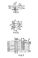
- a polarizer is shown in Fig. 7 as polarizer 50 having alternate layers 54 and 56 of molecularly-oriented, highly- birefringent material and of isotropic or functionally isotropic material.
- the layers 54 are each composed of a molecularly oriented birefringent material.
- the material may comprise poly[2,2'-bis(trifluoromethyl)-4,4'-biphenylene] 2", 2"'-dimethoxy-4",4"'-biphenyldicarboxamide.
- Other materials can also be utilized in forming the birefringent layer and should be selected to have as great a difference between the two indices of refraction as possible since the number of layers in the polarizer can be substantially decreased when using birefringent materials having a greater difference between their indices.of refraction.
- the isotropic layers 56 may be.composed of a number of different materials with the requirement that its refractive index substantially match one of the refractive indices of the birefringent material layers on either side thereof. Some examples of materials which are useful for this purpose include polyacrylates, poly(2,2'-dibromo-4,4'-biphenylene)4",4"'-stilbenedicarboxamide, silicon oxides or titanium dioxides.
- the isotropic layers can be provided, for example, by vacuum deposition so that their thickness can be precisely controlled. Alternately, the isotropic layer may be co-extruded simultaneously with the birefringent layers interleaved therebetween.
- each birefringent layer lies in a plane parallel to the planar substrate surface 60. This is accomplished, for example, through the use of a stretch orientation operation. Layer thickness can be suitably controlled by the extrusion process and allowances for dimensional changes expected in the layer thickness during the stretching step can be made.
- Fig. 7 schematically shows a number of light rays 62 incident on polarizer 50 and traveling in a direction perpendicular to the surface thereof.
- the rays 62b are unreflected at the interface 64 because the refractive index for "0" rays 62b in layer 54 matches that of layer 56 and in fact, these rays 62b will pass through all layers 54 and 56 unreflected and comprise that portion of the light incident on the polarizer that is transmitted thereby.
- each layer 54 and 56 is made to have an optical thickness of one-quarter-the length of a selected wavelength.
- the optical thickness is equal to the physical thickness multiplied by the index of refraction of the layer material.
- the wavelength selected is preferably in the middle of the visible spectrum, for example, 550 nm so that the polarizer is effective over a substantial range of visible light.
- This arrangement utilizes optical interference to enhance the efficiency of the polarizer.
- the following discussion relates to phase changes in a light wave, not to changes in the polarization azimuth of the light wave.
- the ray 62a suffers no phase change on reflection at interface 64 due to the rule as stated above. Now as the remaining portion of ray 62a strikes the second interface 66,. it has traveled through two layers suffering a phase change of ⁇ /2 + ⁇ /2 in one direction and ⁇ /2 + ⁇ /2 on reflection. The ray 62a will also suffer a phase change of ⁇ on reflection due to the above rule and the total phase change will equal 4 ⁇ /2 + ⁇ or 3 ⁇ . Thus, in accordance with this analysis, the ray 62a will always suffer a phase change of some multiple of ⁇ as it is reflected from each and every interface in the multilayer polarizer.
- Each reflected component 62c of ray 62a and other such similar rays will reinforce one another resulting in substantially total reflection of the-one polarized component of incident light represented by ray 62a providing the number of layers and interfaces are sufficient.
- the other component 62b will pass undisturbed through the multilayer polarizer 50 so long as the refractive index of the isotropic layers 56 match one of the refractive indices of the birefringent layers 54. Since substantially none of the rays 62a are ⁇ transmitted, the entire amount of light output from polarizer 50 consists of rays 62b, all polarized in one direction.
- Fig. 8 an optical beam-splitter device of the present invention embodying a layer of birefringent polymer.
- Beam splitter 70 comprises prisms 72a and 72b of isotropic material such as glass joined in a Nicol configuration with a layer 74 of molecularly oriented birefringent polymer therebetween.
- Elements 72a and 72b can be composed of a variety of glass or other isotropic materials and will have a.perpendicular index of 'refraction greater than that of the polymer layer 74 between such elements.
- a unidirectionally stretched layer 74 of poly-[2,2'-bis(trifluoromethyly-4,4'-biphenylene]-2,2'-dimethoxy-4,4'-biphenyl having a perpendicular index of refraction of about 1.65 and a unidirectional stretch direction as indicated in Fig. 8 can be utilized between isotropic glass elements 72a and 72b of refractive index 1.8.
- unpolarized light 76 enters element 72a and a portion thereof is reflected at the interface of element 72a and layer 74 so as to emerge as plane-polarized light 78.
- a portion of light 76 is refracted by layer 74 and emerges from element 72b as oppositely plane-polarized light 80.
- Light 76 is thus split into separate beams of oppositely polarized light by beam splitter 70.
- This example illustrates the preparation of poly(2,2'-dibromo-4,4'-biphenylene)-p,p'-biphenylene dicarboxamide and the preparation therefrom of birefringent polymeric films.
- reaction vessel a resin-making kettle equipped with a mechanical stirrer, nitrogen inlet tube and calcium chloride drying tube
- a reaction vessel was heated while simultaneously flushing the vessel with nitrogen.
- 1.63 g of anhydrous lithium chloride and 0.5746 g (0.001679 mole) of.sublimed 2,2'-dibromobenzidine were added while maintaining a positive nitrogen pressure.
- the reaction vessel was fitted with a thermometer and a rubber stopple (a rubber membrane- like sealing lid capable of receiving a syringe and of sealing itself upon removal of the syringe).
- the ice bath was removed from the reaction vessel and the temperature was observed to rise to 20°C in 30 minutes at which point the reaction solution became milky in appear- - ance.
- the reaction vessel was placed in an oil bath (40°C) and the reaction mixture was warmed for 30 minutes. The reaction mixture became clear. The temperature of the reaction mixture rose during the warming to a maximum temperature of 55°C at which temperature the reaction mixture was stirred for 1 hour.
- the reaction product, a 3 % wt./vol. polymer solution (3 g of polymer per 100 ml of reaction solvent) was cooled to '40°C and poured into 200 ml of ice-water in a blender.
- the resulting'fibrous solid was filtered and washed (in the blender) twice each with water, acetone and ether.
- the product was dried in a vacuum oven at 15 mm pressure and 90°C for 18 hours.
- the product, obtained in 95.4 % yield, was a white fibrous polymeric material having the following recurring structural units:
- the inherent viscosity of a polymer solution (0.5 g of the polymer of Example 1 per 100 ml of a solution of 5 g lithium chloride per 100 ml of dimethylacetamide) was 3.54 dl/g at 30°C.
- Polymeric films were prepared from the polymeric material of Example 1 by casting (onto glass plates) solutions of the polymeric material in a 5 % wt./vol. solution of lithium chloride and dimethylacetamide (5 g lithium chloride per 100 ml of dimethylacetamide).
- the concentration of polymer ranged from 0.5 to 5 % wt./vol., i.e., from 0.5 g to 5 g polymer per 100 ml of the lithium chloride/dimethylacetamide solution.
- the glass plate carrying the puddle-cast polymer solution was immersed in water (after minimal evaporation of solvent). The polymer film was observed to gel and a transparent and colourless unoriented film separated from the glass plate.
- the resulting film was soaked for several hours in water to effect extraction of occluded lithium chloride and solvent, soaked in acetone and dried in a vacuum oven at 90°C and 15 mm pressure.
- Stretched polymeric films were prepared in the following manner. Water-swollen films (obtained by soaking the polymer films for several hours for removal of occluded lithium chloride and solvent as aforedescribed) were cut into strips. The strips were mounted between the jaws of a mechanical unidirectional stretcher. The strips were stretched (in air at 220°C) to about 50 % elongation, to effect film orientation. The resulting films were optically transparent. Birefringence, measured with the aid of a quartz wedge, was 0.293.
- This example illustrates the preparation of poly(2,2'-di- nitro-4,4'-biphenylene)-o,o'-dinitro-p,p'-biphenylene dicarboxamide and the preparation therefrom of birefringent polymeric films.
- reaction vessel a resin-making kettle equipped with a mechanical stirrer, nitrogen,inlet tube and calcium chloride drying tube
- NMP N-methylpyrrolidone
- TEU anhydrous distilled tetramethylurea
- the ice bath was removed from the reaction vessel and the temperature was observed to rise to 20°C in 30 minutes at which point the reaction solution was heated in stages up to 90°C over a period of 2.5 hours.
- the reaction product a 3 % wt./vol. polymer solution (3 g of polymer per 100 ml of reaction solvent) was cooled to 40°C and poured into 200 ml of ice-water in a blender. The resulting gelatinous solid was filtered and washed (in the blender) twice each with water, acetone and ether. The product was dried in a vacuum oven at 15 mm ' Hg pressure and 90°C for 18 hours.
- the polymeric product, obtained in 88 % yield was a dark-yellow powder having the following recurring structural units:
- the inherent viscosity of a polymer solution (0.5 g of the polymer of Example 2 per 100 ml of a solution of 5 g lithium chloride per 100 ml of dimethylacetamide) was 1.40 dl/g at 30 °C.
- Thermogravimetric analysis showed that onset of degradation of the polymer of Example 2 occurred at 360°C in nitrogen and at 300°C in air. Differential scanning calorimetry and thermal mechanical analysis of film samples showed a rep ro - ducible transition at about 190°C.
- Polymeric films' were prepared from the polymeric material of Example 2 by casting (onto glass plates) a solution of the polymeric material in a 5 % wt./vol. solution of lithium chloride and dimethylacetamide (5 g lithium chloride per 100 ml of dimethylacetamide).
- the concentration of polymer was 5 % wt./vol., i.e., 5 g polymer per 100 ml of the lithium chloride/dimethylacetamide solution.
- the glass plate carrying the puddle-cast polymer solution was immersed in water (after most of the solvent had evaporated).
- the polymer film was observed to gel and a transparent, yellow unoriented film separated from the glass plate.
- the resulting film was soaked for several hours in water to effect extraction of occluded lithium chloride and solvent.
- Stretched polymeric films were prepared in the following manner. Water-swollen films (obtained by soaking the polymer films for several hours for removal of occluded lithium chloride and solvent as aforedescribed) were cut into strips. The strips were mounted between the jaws of a mechanical unidirectional stretcher. The strips were stretched (in boiling ethylene glycol) to about 60 % elongation, to effect film orientation. The resulting polymeric strips were optically transparent. Birefringence, measured with the aid of a quartz wedge, and by index matching, was 0.33. The calculated isotropic refractive index was 1.75. Wide-angle X-ray analysis of the birefringent films showed crystallinity to be less than 10 % by weight.
- This example illustrates the preparation of poly(2,2'-dibromo-4,4'-biphenylene)-o,o'-dibromo-p,p'-biphenylene di- catboxamide and the preparation therefrom of birefringent polymeric films.
- reaction vessel a resin-making kettle equipped with a mechanical stirrer, nitrogen inlet tube and calcium chloride drying tube
- NMP N-methylpyrrolidone
- TEU anhydrous distilled tetramethylurea
- reaction mixture began to thicken and streaming birefringence (but not stir opalescence) was observed.
- Stirring was continued for an additional 30 minutes at 7°C and the ice bath was removed from the reaction vessel. The temperature of the reaction mixture rose to 25°C (in 90 minutes) and the reaction mixture was then slowly heated to 100° C over a two-hour period.
- the reaction product a 4 % wt./vol. polymer solution (4-g of polymer per 100 ml of reaction solvent) was cooled to 40°C and poured into 200 ml of ice-water in a blender. The resulting fibrous solid was filtered and washed (in the blender) twice each with water, acetone and ether. The product was dried in a vacuum oven at 15 mm pressure and 90°C for 18 hours. The product, obtained in 96.6 % yield, was a white.fibrous polymeric material having the following recurring structural units:
- the inherent viscosity of a polymer solution (0.5 g of the polymer of Example 3 per 100 ml of a solution of 5 g lithium chloride per 100 ml of dimethylacetamide) was 2.04 dl/g at 30 °C.
- Molecular weight determination based on light scattering indicated 2.72 x 10.5, and by gel permeation chromatography, a molecular weight of 5.66 x 10 4 .
- Thermogravimetric analysis showed that onset of degradation of the polymer of Example 3 occurred at 530°C in nitrogen. Thermal mechanical analysis of film samples showed a reproducible transition at about 120°C.
- Polymeric films were prepared from the polymeric material of Example 3 by casting (onto glass plates) solutions of the polymeric material in a 5 % wt./vol. solution of lithium chloride and dimethylacetamide.(5 g lithium chloride per 100 ml of dimethylacetamide).
- the concentratio of polymer ranged from 0.5 to 5 % wt./vol., i.e. from 0.5 g to 5 g polymer per 100 ml of the lithium chloride/dimethylacetamide solution.
- the.glass plate carrying the puddle-cast polymer solution was immersed in water (after most of the solvent had evaporated). The polymer film was observed to gel and a transparent, colourless unoriented film separated from the glass plate.
- the resulting film was soaked for several hours in water to effect extraction of occluded lithium chloride and solvent, soaked in acetone and dried in a vacuum oven at 90°C and 15 mm Hg pressure.
- Stretched polymeric films were prepared in the following manner. Water-swollen films (obtained by soaking the polymer films for several hours for removal of occluded lithium chloride and solvent as aforedescribed) were cut into strips. The strips were mounted for stretching between the jaws of a mechanical unidirectional stretcher. Strips were stretched, in some instances, in air at 220°C and, in other instances, in boiling ethylene glycol. Elongation ranged from 60 % to 65 %. Infrared dichroism indicated that the films were less than 65 % oriented. The films were optically transparent. Birefringence, measured with the aid of a quartz wedge, was 0.390. Wide-angle X-ray analysis of the birefringent polymer films showed them to be less than 10 % by weight crystalline.
- This example illustrates the preparation of poly(2,2'-di- chloro-5,5'-dimethoxy-biphenylene)-o,o'-dibromo-p,p'-biphenylene dicarboxamide and the preparation therefrom of birefringent polymeric films.
- reaction vessel a resin-making kettle equipped with a mechanical stirrer, nitrogen inlet tube and calcium chloride drying tube
- NMP N-methylpyrrolidone
- TEU TMA
- reaction product a 2.82 % wt./vol. light-yellow polymer solution (2.82 g of polymerper 100 ml of reaction solvent) was cooled to 40°C and the resulting gelatinous, transparent mass was added to 200 ml of ice-water in a blender. The resulting rubbery solid was filtered and washed (in the blender) twice each with water, acetone and ether. The product was dried in a vacuum oven at 15 mm Hg pressure and 90°C for 18 hours. The product, obtained in 99.-3 % yield, was a very pale-yellow fibrous polymeric material having the following recurring structural units:
- the inherent viscosity of a polymer solution (0.5 g of the polymer of Example 4 per 100 ml of a solution of 5 g lithium chloride per 100 ml of dimethylacetamide) was 5.75 dl/g at 30°C.
- Polymeric films were prepared from the polymeric material of Example 4 by casting (onto glass plates) solutions of the polymeric material in a 5 % wt./vol. solution of lithium chloride and dimethylacetamide (5 g lithium chloride per 100 ml of dimethylacetamide).
- the concentration of polymer was 2 % wt./vol., i.e., 2 g of polymer per 100 ml of the lithium chloride/dimethylacetamide solution.
- the glass plate carrying the puddle-cast polymer solution was immersed in water (after minimal evaporation of solvent). The polymer film was observed to gel and a transparent, colourless unoriented film separated from the glass plate.
- the resulting film was soaked for 2 days in water to effect extraction of occluded lithium chloride and solvent, soaked in acetone and dried in a vacuum oven at 90°C and 15 mm pressure. Refractive index, measured by interferometry was 1.87.
- Stretched polymeric films were prepared in the following manner. Water- ollen films (obtained by soaking the polymer films for several hours for removal of occluded lithium chloride and solvent as aforedescribed) were cut into strips. The strips were mounted between the jaws of a mechanical unidirectional stretcher. The strips were stretched (in air at 220°C) to about 50 % elongation, to effect film orientation. The stretched films were optically transparent. Birefringence, measured with the aid of a quartz wedge, was 0.24.
- This example illustrates the preparation of poly(2,2'-dibromo-4,4'-biphenylene)-octafluoro-p,p'-biphenylene dicarboxamide and the preparation therefrom of birefringent polymeric films.
- reaction vessel a resin-making kettle equipped with a mechanical stirrer, nitrogen inlet tube and calcium chloride drying tube
- NMP N-methylpyrrolidone
- TEU TMA
- the resulting reaction product a 3 % wt./vol. polymer solution (3 g of polymer per 100 ml of reaction solvent) was cooled to 40°C and poured into 200 ml of ice-water in a blender. The resulting fibrous solid was filtered and washed (in the blender) twice each with water, acetone and ether. The product was dried in a vacuum oven at 15 mm pressure and 90°C for 18 hours. The product, obtained in 87.6 % yield, was a white fibrous polymeric material having the following recurring structural units:
- the inherent viscosity of a polymer solution (0.5 g of the polymer of Example 5 per 100 ml of a solution of 5 g lithium chloride per 100 ml of dimethylacetamide) was 1.68 dl/g at 30°C.
- Thermogravimetric analysis showed that onset of degradation of the polymer of Example 5 occurred at 325°C in nitrogen and at 350°C in air. Differential scanning calorimetry showed a reproducible transition at about 155°C.
- Polymeric films were prepared from the polymeric material of Example 5 by casting (onto glass plates) solutions of the polymeric material in a 2 % wt./vol. solution of lithium chloride and dimethylacetamide (2 g lithium chloride per 100 ml of dimethylacetamide).
- the concentration of polymer ranged from 0.5 to 5 % wt./vol., i.e., from 0.5 g to 5 g polymer per 100 ml of the lithium chloride/. dimethylacetamide solution.
- the glass plate carrying the puddle-cast polymer solution was immersed in water (after minimal evaporation of solvent). The polymer was observed to gel and a transparent and I colourless unoriented film separated from the glass plate.
- the resulting film was soaked for several hours in water to effect extraction of occluded lithium chloride and solvent, soaked in acetone and dried in a vacuum oven at 90°C and 15 mm Hg pressure. Refractive index, measured by interferometry was 1.74.
- Stretched polymeric films were prepared in the following manner. Water-swollen films (obtained by soaking the polymer films for several hours for removal of occluded lithium chloride and solvent as aforedescribed) were cut into strips. The strips were mounted between the jaws of a mechanical unidirectional stretcher. The strips were oriented by stretching (in air at 200°C) to an elongation in the range of 50 to 55 %. The polymeric strips were optically transparent. Birefringence, measured with the aid of a quartz wedge, was 0.35. Strips were also stretched in methanol at 25°C to an elongation of 55 %. Measurement of birefringence for such stretched films showed a birefringence of 0.44.
- This example illustrates the preparation of poly(2,2',3,3', 4,4',6,6'-octafluoro-4,4'-biphenylene) carbohydrazide and the preparation therefrom of birefringent polymeric films.
- reaction vessel a resin-making kettle equipped with a mechanical stirrer, nitrogen inlet tube and calcium chloride drying tube
- NMP N-methylpyrrolidone
- TNU anhydrous distilled tetramethylurea
- Lithium carbonate (0.0890 g; 0.0024 mole) was added to the reaction mixture, stirring was continued for 30 minutes at 4°C and the ice bath was removed. As the temperature of the reaction mixture rose to 25°C during the subsequent 60 minutes, the reaction solution first became cloudy and, then, a white precipitate formed. Over the next 30 minutes, the reaction mixture was warmed to 40°C at which time the reaction mixture became homogeneous. The reaction temperature was raised to 70°C and maintained for 1 hour. No increase in viscosity was apparent.
- the reaction product a 1.99 % wt./vol. polymer solution (1.99 g of polymer per 100 ml of reaction solvent) was cooled to 40°C and poured into 200 ml of ice-water in a blender. The resulting powdery solid was filtered and washed (in the blender) twice each with water, acetone and ether. The product was drisd in a vacuum oven at 15 mm Hg pressure and 90°C for 18 hours. The polymeric product, obtained in 95.4 % yield, was a white solid material having the following recurring structural units:
- the inherent viscosity of a polymer solution (0.5 g of the polymer of Example 6 per 100 ml of a solution of 5 g lithium chloride per 100 ml of dimethylacetamide) was 1.16 dl/g at 30°C.
- the molecular structure of the polymer of Example 6 was confirmed by infrared spectroscopy.
- Polymeric films were prepared from the polymeric material of Example 6 by casting (onto glass plates) solutions of the polymeric material in a 2 % wt./vol. solution of lithium chloride and dimethylacetamide (2 g lithium chloride per 100 ml of dimethylacetamide).
- the concentration of polymer ranged from 0.5 to 5 % wt./vol., i.e., from 0.5 g to 5 g polymer per 100 ml of the lithium chloride/ dimethylacetamide solution.
- the glass plate carrying the puddle cast polymer solution was immersed in water (after evaporating the solvent for 1 hour). The polymer film was observed to gel, and a physically weak, cloudy and colourless film separated from the glass plate.
- the resulting film was soaked for several hours in water to effect extraction of occluded lithium chloride and solvent, soaked in acetone ' and dried in a vacuum oven at 90°C and 15 mm pressure.
- the films were not of sufficient strenth to undergo stretching.
- This example illustrates the preparation of poly(2,2'-dibromo-4,4'-biphenylene)-trans-p,p'-stilbene dicarboxamide and the preparation therefrom of birefringent polymeric films.
- reaction vessel a resin-making kettle equipped with a mechanical stirrer, nitrogen inlet tube and calcium chloride drying tube
- NMP N-methylpyrrolidone
- the ice bath was removed from the reaction vessel, and when the temperature reached 20°C (in 30 minutes), the reaction solution had become sufficiently viscous as to begin to climb the shaft of the mechanical stirrer. A maximum reaction temperature of 55°C was reached. Stirring was stopped and the mixture was heated overnight at a temperature of 55°C.
- the reaction product a viscous polymer solution of 3 % wt./vol. concentration (3 g of polymer per 100 ml of reaction solvent) was diluted with 130 ml of 2 % wt./vol. lithium chloride in dimethylacetamide. The resulting polymer solution'was poured into 200 ml of ice and water in a blender.
- the resulting fibrous solid was filtered and washed (in the blender) twice each with water, acetone and ether.
- the product was dried in a vacuum oven at 15 mm Hg pressure and 90°C for 18 hours.
- the polymeric product, obtained in 100 % yield, was a very light-yellow fibrous solid having the following recurring structural units:
- the inherent viscosity of a polymer solution (0.5 g of the polymer of Example 7 per 100 ml of a solution of 5 g lithium chloride per 100 ml of dimethylacetamide) was 9.04 dl/g at 30°C.
- Thermogravimetric analysis showed that the onset of degradation of the polymer-of Example 7 occurred at 470°C in nitrogen and at 515°C in air.
- Differential scanning calorimetry and thermal mechanical analysis of film samples detected a reproducible transition at about 225°C.
- Polymeric films were prepared from the polymeric material of Example 7 by casting (onto glass plates) solutions of the polymeric material in a 5 % wt./vol. solution of lithium chloride and dimethylacetamide (5 g lithium chloride per 100 ml of dimethylacetamide).
- the concentration of polymer ranged from 1 to 5 % wt./vol., i.e., from 1 g to 5 g polymer per 100 ml of the lithium chloride/ dimethylacetamide solution.
- the glass plate carrying the puddle-cast polymer solution was immersed in water (after minimal evaporation of solvent). The polymer was observed to gel and a transparent and colourless unoriented film separated from the soaked glass plate.
- the resulting film was soaked for several hours in water to effect extraction of occluded lithium chloride and solvent, soaked in acetone and dried in a vacuum oven at 90°C and 15 mm Hg pressure.
- Stretched polymeric films were prepared in the following manner. Water-swollen films (obtained by .soaking the polymer films for several hours for removal of occluded lithium chloride and solvent as aforedescribed) were cut into strips. The strips were mounted between the jaws of a mechanical unidirectional stretcher. The strips were stretched (in air at 220°C) to about 55 to 55 % elongation, to effect film orientation. The stretched films were optically transparent. Infrared dichroism indicated that the stretched films were less than 65 % by weight oriented; the modulus was 0.27 x 10 6 kg/m2. Wide-angle X-ray analysis of the films showed crystallinity to be less than 10 % by weight. Birefringence, measured with the aid of a quartz wedge, was 0.589.
- the resulting transparent, colourless film strips were soaked in water and cut to about 25.4 to 50.8 mm for testing.
- the partially oriented strips of film produced by the extrusion were further oriented by stretching in the manner described in the Examples hereof. Stretching was effected in air at a temperature of 180°C. Elongation was to the break point, in the range of about 40 % to 50 %.
- the stretched strips were optically transparent.
- Infrared dichroism indicated that the films were 85 % oriented.
- Measurement of birefringence utilizing a quartz wedge provided a birefringence value of 0.977.
- Measurement by resort to interferometry provided a value of 0.865.
- This'example illustrates the preparation of poly(2,2'-dibromo-4,4'-biphenylene)-trans- ⁇ -bromo-biphenylene dicarboxamide and the preparation therefrom of birefringent polymeric films.
- reaction vessel a resin-making kettle equipped with a mechanical stirrer, a pressure-equalizing dropping funnel, a nitrogen inlet tube and calcium chloride drying tube
- 1.5 g of anhydrous lithium chloride and 0.4779 g (0.001397 mole) of sublimed 2,2'-dibromo-benzidine were added while maintaining a positive nitrogen pressure.
- reaction vessel was fitted with a thermometer and a rubber stopple and 15 ml of anhydrous distilled N-methyl- pyrrolidone (NMP) and 5 ml-of anhydrous distilled tetramethylurea (TMU) were carefully added with the aid of syringes.
- NMP N-methyl- pyrrolidone
- TNU anhydrous distilled tetramethylurea
- the resulting mixture was stirred and warmed to 40°C until all solids had dissolved.
- the solution was ther cooled in a bath.of ice and salt to a temperature of 0° C . A small amount of lithium chloride precipitation was observed.
- Recrystallized ⁇ -bromo-p,p'-stilbene dicarbonyl chloride (0.5366 g; 0.001397 mole) was quickly added by means of a funnel to the stirred 2,2'-dibromobenzidine solution.
- An additional 10 ml of TMU (at a temperature of 25°C) were added through the funnel to the reaction mixtur The temperature of the reaction mixture did not rise above a temperature of 4°C. After stirring for 15 minutes, the reaction mixture began to thicken and streaming birefringence (but not stir opalescence) was observed. Stirrir was continued for an additional 30 minutes at 4°C.
- the ice bath was removed from the reaction vessel and the temperature was observed to rise to 25°C in 90 minutes at which point the reaction mixture had become sufficiently viscous as to climb the shaft of the mechanical stirrer. Over the next 90 minutes, the very pale-yellow reaction mass was gently warmed with intermittent stirring; the maximum temperature reached was approximately 70°C.
- the reaction product a 3 % wt./vol. polymer solution (3 g of polymer per 100 ml of reaction solvent) was cooled to 40°C and poured into 200 ml of ice-water in a blender. The resulting fibrous solid was filtered and washed (in the blender) twice each with water, acetone and ether. The product was dried in a vacuum oven at 15 mm Hg pressure ar 90°C for 18 hours. The product, obtained in 95.4 % yield, was a light-yellow fibrous polymeric material having the following recurring structural units:
- the inherent viscosity of a polymer solution (0.5 g of the polymer of Example 8 per 100 ml of a solution of 5 g lithium chloride per 100 ml of dimethylacetamide) was 7.81 dl/g at 30°C.
- Polymeric films were prepared from the polymeric material of Example 8 by casting (onto glass plates) solutions of the polymeric material in a 5 % wt./vol. solution of lithium chloride and dimethylacetamide (5 g lithium chloride per 100 ml of dimethylacetamide).
- the concentration of polymer ranged from 0.5 to 5 % wt./vol., i.e., from 0.5 g.to 5 g polymer per 100 ml of the lithium chloride/dimethylacetamide solution.
- the glass plate carrying the puddle-cast. polymer-solution was immersed in water (after minimal evaporation of:solvent). The polymer was observed to gel and a transparent and colourless unoriented film separated from the soaked glass plate.
- the resulting film was soaked for several hours in water to effect extraction of occluded lithium chloride and solvent, soaked in acetone and dried in a vacuum oven at 90°C and 15 mm Hg pressure Refractive index, measured by interferometry, was 2.07.
- Stretched polymeric films were prepared in the following . manner. Water-swollen films (obtained by soaking the polymer films for several hours for removal of occluded lithium chloride and solvent as aforedescribed) were cut into strips. The strips were mounted between the jaws of a mechanical unidirectional stretcher. The strips were stretched (in air at 220°C) to about 60.% to 65 % elongation, to effect film orientation. The stretched strips were optically transparent. Birefringence, measured with the aid of a quartz wedge, was 0.680.
- This example illustrates the preparation of poly(2,2'-dibromo-4,4'-biphenylene)- ⁇ , ⁇ '-dimethylmuconamide and the preparation therefrom of birefringent polymeric films.
- reaction vessel a resin-making kettle equipped with a mechanical stirrer, a pressure-equalizing dropping funnel, a nitrogen inlet tube and calcium chloride drying tube
- a reaction vessel was heated while simultaneously flushing the vessel with nitrogen.
- 0.4 g of anhydrous lithium chloride and 0.8519 g (0.00249 mole) of sublimed 2,2'-dibromo-benzidine were added while maintaining a positive nitrogen pressure.
- the reaction vessel was fitted with a thermometer and a rubber stopple and 10 ml of anhydrous distilled N-methylpyrrolidone (NMP) were carefully added with the aid of a syringe.
- NMP N-methylpyrrolidone
- the addition funnel was rinsed with 6 ml of NMP which was also added dropwise to the reaction mixture in order to prevent the temperature of the reaction mixture from rising above 1°C.
- NMP NMP which was also added dropwise to the reaction mixture in order to prevent the temperature of the reaction mixture from rising above 1°C.
- 0.354 g of solid lithium carbonate was added all at once to the reaction mixture.
- the ice bath was removed from the reaction vessel and the' temperature of the reaction mixture was allowed to rise to 25°C over a one-hour period during which time a thick paste had formed.
- the temperature of the reaction mixture was increased to 65°C over the next 20 minutes producing a : mixture which could no longer be stirred.
- reaction product a 5.36 % wt./vol. polymer solution (5.6 g of polymer per 100 ml of reaction solvent) was observed to exhibit considerable streamingbirefringence upon application of low mechanical stress; stir opalescence was not, however, observed.
- the polymer solution was poured into a blender containing 200 ml of ice-water and the resulting fibrous solid was filtered and washed (in the blender) twice each with water, acetone and ether.
- the product was dried in a vacuum oven at 15 mm Hg pressure and 90°C for 18 hours.
- the product, obtained in 94.7 % yield, was a white fibrous polymeric material having the following recurring structural units:
- the inherent viscosity of a polymer solution (0.5 g of the I polymer of Example 9 per 100 ml of a solution of 5 g lithium chloride per 100 ml of dimethylacetamide) was 4.69 dl/g at 30°C..
- Thermogravimetric analysis showed that the onset of degradation occurred at 360°C in nitrogen and at 310°C in air. Differential scanning calorimetry and thermal mechanical analysis of film samplesshowed a reproducible transition at about 185°C.
- Polymeric films were prepared from the polymeric material of Example 9 by casting (onto glass plates) solutions of the polymeric material in a 5 % wt./vol. solution of lithium chloride and dimethylacetamide (5 g lithium chloride per 100 ml of dimethylacetamide).
- the concentration of polymer ranged from 2 to 4 % wt./vol., i.e., from 2 g to 4 g polymer per 100 ml of the lithium chloride/dimethylacetamide solution.
- the glass plate carrying the puddle-cast polymer solution was immersed in water (after minimal evaporation of solvent). The polymer film was observed to gel and a transparent and colourless unoriented film separated from the glass plate.
- the resulting film was soaked for several hours in water to effect extracttion of occluded lithium chloride and solvent, soaked in acetone and dried in a vacuum oven at 90°C and 15 mm Hg pressure.
- Refractive index measured by interferometry,.was 1.91.
- Stretched polymeric films were prepared in the following manner. Water-swollen films (obtained by soaking the polymer films for several hours for removal of occluded lithium chloride and solvent as aforedescribed) were cut into strips. The strips were mounted between the jaws of a mechanical stretcher and were unidirectionally stretched, successively, in steam, acetone and boiling ethylne glycol (all of which function as plasticizers). The strips were stretched to an elongation of from 35 % to 45 %. The film strips were further elongated (up to 60%) by stretching in air at 200°C. The stretched strips were optically transparent. Optical retardation was measured with a calibrated quartz wedge; film thickness was measured with a micrometer. Birefringence, measured by means of a quartz wedge, was 0.40.
- an unsubstituted polyamide was prepared and evaluated in the following manner.
- reaction vessel a resin-making kettle equipped with mechanical stirrer, nitrogen inlet tube and calcium chloride drying tube
- TNU anhydrous distilled tetramethyl urea
- 8.04 g (0.04 mole) of vacuum-distilled p-thionylaminobenzoyl chloride and 0.52 g (0.012 mole) of lithium chloride were added while maintaining a positive nitrogen pressure.
- the resulting reaction mixture was stirred for ten minutes at room temperature and 1.68 g (0.04 mole) of lithium hydroxide monohydrate were added while vigorously stirring.
- the reaction mixture was then stirred for 1 hour at room temperature.
- reaction mixture After a period of 7 additional minutes, the reaction mixture became cloudy and was observed to thicken.
- the polymeric reaction product after 20 minutes, thickened sufficiently to adhere the shaft of the mechanical stirrer. After one-half hours, the reaction mixture, which could not be stirred, was heated. An additional quantity (14 ml) of TMU was added at which point the reaction mixture still could not be stirred. The reaction mixture was then heated to 130° C without stirring. After 2 hours of heating at 130°C, pliability of polymeric reaction mass increased and the product appeared to have partially_dissolved.
- the reaction product was stored in the reaction vessel overnight and was washed with water, filtered and washed with acetone then ether. The product, poly-(p-benzamide) was dried in a vacuum oven at 80°C for 2 hours.
- the inherent viscosity of -a polymer solution of poly (p-penzamide) in sulfuric acid was 1.60 dl/g at 30°C.
- Polymeric films of poly(p-benzamide) were prepared by casting a solution of the polymeric material in a 5 % wt./ vol. solution of lithium chloride and dimethylacetamide (5 g lithium chloride per 100 ml of dimethylacetamide). The concentration of polymer was 5 % wt./vol., i.e., 5 g polymer per 100 ml of the lithium chloride/dimethylacetamide solution. The cast polymer film was dried in a vacuum oven at 90°C overnight. The polymer film was an opaque, white flexible film. Additional films were formed by puddle-casting the solution as aforedescribed onto glass plates.
- the glass plate carrying the puddle-cast polymer solution was immersed in water (after most of the. solvent had evaporated).
- the p p lymer film which separated from the glass plate was a tough, transparent, flexible film. The resulting film was soaked for several hours in water to effect extraction of occluded lithium chloride and solvent.
- Stretched polymeric films were prepared in the following manner. Water-swollen films (obtained by soaking the polymer films for several hours for removal of occluded lithium chloride and solvent as aforedescribed) were cut into strips. The strips were mounted between the jaws of a mechanical stretcher and were unidirectionally stretched, successively, in steam and in air (at 200°C). The strips were stretched to an elongation of approximately 10 %. The resulting streched films were clouded in appearance. Optical retardation was measured with a calibrated quartz wedge; film thickness was measured with a micrometer. B ire- fringence, measured by means of a quartz wedge, was 0.23.
- This example illustrates the preparation of poly-[2,2 1- bis-(trifluoromethyl)-4,4'-biphenylene] -trans-p,p'-stilbene dicarboxamide and the preparation therefrom of birefringent polymeric films.
- reaction vessel a resin-making kettle equipped with a mechanical stirrer, nitrogen inlet tube and. calcium chloride drying tube
- a reaction vessel was heated while simultaneously flushing the vessel with nitrogen.
- 1.5 g of anhydrous lithium chloride and 0.51-71 g (0.001615 mole) of recrystallized 2,2'-bis,(trifluoromethyl)-benzidine were added while maintaining a positive nitrogen pressure.
- the reaction vessel was fitted with a thermometer and a rubber stopple and 10 ml of anhydrous distilled tetramethylurea (TMU) were carefully added with the aid of syringes.
- TNU anhydrous distilled tetramethylurea
- the inherent viscosity of a polymer solution (0.5 g of the polymer of Example 11 per 100 ml of a solution of 5 g lithium chloride per 100 ml of dimethylacetamide) was 4.735 dl/g at 30°C.
- the molecular structure of the polymer was confirmed by infrared spectroscopy.
- Thermogravimetric analysis showed that the onset of degradation of the polymer of Example 11 occurred at 500° C in nitrogen and at 410°C in air.
- Differential scanning calorimetry and thermal mechanical analysis of film samples detected a reproducible transition at about 185° C .
- Polymeric films were prepared from the polymeric material of Example 11 by casting (onto glass plates) solutions of the polymeric material in a 5 % wt./vol. solution of lithium chloride and dimethylacetamide (5 g lithium chloride per .100 ml of dimethylacetamide).
- the concentration of polymer ranged from 1.0 to 5 % wt./vol., i.e., from 1.0 g to 5 g polymer per 100 ml of the lithium chloride/dimethylacetamide solution.
- the glass plate carrying the puddle-cast polymer solution was immersed in water (after minimal evaporation of solvent). The polymer film was observed to gel and a transparent and colourless unoriented film separated from the glass plate.
- the resulting film was soaked for several hours in water to effect extraction of occluded lithium chloride and solvent, soaked in acetone and dried in a vacuum oven at 90°C and 15 mm Hg pressure. Refractive index, measured by interferometry, was 1.997.
- Stretched polymeric films were prepared in the following manner. Water-swollen films (obtained by soaking the polymer films for several hours for removal of occluded lithium chloride and solvent as aforedescribed) were cut into strips. The strips-were mounted between the jaws of a mechanical unidirectional stretcher. The strips were stretched (in air at 220°C) to about 60 to 65 % elongation, to effect film orientation. The stretched films were optically transparent. Birefringence, measured with the aid of a quartz wedge, was 0.537.
- Solutions of the polymer of-.Example 11 in lithium chloride/ dimethylacetamide, as aforedescribed, were formed into extruded films by the "wet-jet"method whereby the solution of polymer is extruded into an aqueous coagulation bath for gelling of the polymer material.
- the resulting tans- parent, colourless film strips were soaked in water and cut to about 25.4 to 50.8 mm for testing.
- the partially oriented strips of film produced by the extrusion were further oriented by stretching in the manner described in the Examples hereof. Stretching was effected to an elongation of less than 20 %.
- the stretched strips were. optically transparent. Infrared dichroism indicated that the films were 92 % oriented. Measurement of birefringence utilizing a quartz wedge provided a birefringence value of 0.879.
- This example illustrates the preparation of poly-E2,2'-bis-(trifluoromethyl)-4,4'-biphenylene]-2,2'-dimethoxy-4,4'-biphenyl and the preparation therefrom of birefringent polymeric films.
- reaction vessel a resin-making kettle equipped with a mechanical stirrer, a pressure-equalizing dropping funnel, a nitrogen inlet tube and calcium chloride drying tube
- a reaction vessel was heated while simultaneously flushing the vessel with nitrogen.
- the reaction vessel had cooled to room temperature, 3.0 g of anhydrous lithium chloride and 0.4328 g (0.001352 mole) of recrystallized 2,2'-bis(trifluoromethyl)benzidine were added while maintaining a positive nitrogen pressure.
- reaction vessel was fitted with a thermometer and a rubber stopple and 20 ml of anhydrous distilled N-methylpyrrolidinone (NMP) and 20 ml of anhydrous distilled tetramethylurea (TMU) were carefully added with the aid of syringes. The resulting mixture was stirred and warmed to 40°C until all solids had dissolved.
- NMP N-methylpyrrolidinone
- TNU anhydrous distilled tetramethylurea
- the ice bath was removed from the reaction vessel and the temperature was observed to rise to 20°C in 30 minutes at which point the reaction mixture was viscous and opaque. Over the next 75 minutes, the opaque reaction mass was gently warmed to 40°C at which point it became transparent. After stirring at this temperature for the next 18 hours, the reaction mixture was cooled to 30°C and poured into 400 ml of ice-water in a blender. The resulting fibrous solid was filtered and washed (in the blender) twice each with water and ether. The product was dried in a vacuum oven at 15 mm Hg pressure and 90°C for 18 hours. The product, obtained in 99.3 % yield, was an off-white fibrous polymeric material exhibiting solubility in acetone or tetrahydrofuran and having the following recurring structural units:
- the inherent viscosity of a polymer solution (0.5 g of the polymer of Example 12 per 100 ml of a solution of 5 g . lithium chloride per 100 ml of dimethylacetamide) was 1.69 dl/g at 30°C.
- Thermogravimetric analysis showed that the onset of degradation of the polymer of Example 12 occurred at 470°C in nitrogen and at 440°C in air. Differential scanning colorimetry detected a reproducible transition at about 180°C.
- Polymeric films were prepared from the polymeric material of Example 12 by casting (onto glass plates) solutions of the polymeric material in a 5 % wt./vol. solution of lithium chloride and dimethylacetamide (5g lithium chloride per 100 ml of dimethylacetamide).
- the concentration of polymer ranged from 1 % to 5 % wt./vol.,'i.e., from 1.0 g to 5 g polymer per 100 ml of the lithium chloride/dimethylacetamide solution.
- the glass plate carrying the puddle-cast polymer solution was immersed in water (after minimal evaporation of solvent). The polymer was observed to gel and a transparent and colourless unoriented film separated from the soaked glass plate.
- the resulting film was soaked for several hours in water to effect extraction of occluded lithium chloride and solvent, soaked in acetone and dried in a vacuum oven at 90°C and 15 mm Hg pressure.
- This example illustrates the preparation of poly[2,2',3", 2"'-tetrakis(trifluoromethyl)-1,1':4',1":4",1"':4"'- quaterphenylene]-trans-p,p'-stilbenedicarboxamide and the preparation therefrom of birefringent polymeric films.
- A100-ml reaction vessel (a resin-making kettle equipped with a mechanical stirrer, nitrogen inlet tube and calcium chloride drying rube) was heated while simultaneously flushing the vessel with nitrogen. After the reaction vessel had cooled to room temperature, 1.5 ' g of anhydrous lithium chloride and 0.5806 g (0.0009543 mole) of recrystallized 4,4"'-diamino-2,2',3",2"'-tetrakis(trif luoromethyl)1,1':4'-1":4",1"'-quaterphenyl were added while maintaining a positive nitrogen pressure.
- the reaction vessel was fitted with a thermometer and a rubber stopple and 10 ml of anhydrous distilled N-methylpyrrolidone (NMP) and 10 ml of anhydrous distilled tetramethylurea (TMU) were carefully added with the aid of syringes.
- NMP N-methylpyrrolidone
- TNU anhydrous distilled tetramethylurea
- the resulting mixture was stirred and warmed to 40°C until all solids had dissolved.
- the solution was then cooled in a bath of ice and salt to a temperature of -5°C. A small amount of lithium chloride precipitation was observed. Recrystallized trans-p,p'- stilbene dicarbonyl chloride (0.2909 g; 0.0009543 mole) was carefully added by means of a funnel to the stirred diaminoquaterphenyl solution.
- the ice bath was removed from the reaction vessel, and when the. temperature reached 20°C (in 30 minutes), the reaction solution had become very viscous. Over the next 75 minutes, the light yellow, opaque solution was warmed to 45°C. After stirring at this temperature for the next 18 hours, the transparent polymer solution was poured into 200 ml of ice and water in a blender. The resulting fibrous solid was filtered and washed (in the blender) twice each with water and ether. The product was dried in a vacuum oven at 15 mm Hg pressure and 90°C for 18 hours. The polymeric product, obtained in 92.2 % yield, was a very light-yellow fibrous solid having the following recurring structural units:
- the inherent viscosity of a polymer solution (0.5 g of the polymer of Example 13 per 100 ml of a solution of 5 g lithium chloride per 100 ml of dimethylacetamide) was 1.31 dl/g at 30°C.
- the molecular structure of the polymer was confirmed by infrared spectroscopy.
- the polymer was soluble in tetrahydrofuran, in acetone and in various amide-type solvent, with and without added lithium chloride.
- Thermogravimetric analysis showed that the onset of degradation of the polymer of Example 13 occurred at 510°C in nitrogen and at 440°C in air.
- Differential scanning calorimetry and thermal mechanical analysis of film samples detected a reproducible transition at about 187°C.
- Polymeric films were prepared from the polymeric material of Example 13 by casting (onto glass plates) solutions of the polymeric material in a 5 % wt./vol. solution of lithium chloride and dimethylacetamide (5 g lithium chloride per 100. ml of dimethylacetamide).
- the concentration of polymer ranged from 0.5 to 5 % wt./vol., i.e., from 0.5 g to 5 g polymer per 100 ml of the lithium chloride/dimethylacetamide solution.
- the glass plate carrying the - puddle-cast polymer solution was immersed in water (after minimal evaporation of solvent). The polymer film was observed to gel and a transparent and colourless unoriented film separated from the glass plate.
- the resulting film was soaked for several hours in water to effect extraction of occluded W ithium chloride and solvent, soaked in acetone and dried in a vacuum oven at 90°C and 15 mm Hg pressure. Refractive index, measured by interferometry, was 1.810.
- Stretched polymeric films were prepared in the following manner. Water-swollen films (obtained by soaking the polymer films for several hours for removal of occluded lithium chloride and solvent as aforedescribed) were cut into strips. The strips were mounted between the jaws of a mechanical unidirectional stretcher. The strips were stretched in methanol and then in air at 220°C to effect film orientation. The stretched films were optically transparent. Birefringence, measured with the aid of a quartz wedge, was 0.87.
- This example illustrates the preparation of poly-[2,2',3", 2"'-tetrakis(trifluoromethyl)-1,1':4', 1":4", 1"'-4"'- quaterphenylenelterephthalamide and the preparation therefrom of birefringent polymeric films.
- reaction vessel a resin-making kettle equipped with a mechanical stirrer, nitrogen inlet tube and calcium chloride drying tube
- 1.5 g of anhydrous lithium chloride and 0.6301 g (0.001036"mole) of recrystallized 4,4"'-diamino-2,2',3",2"'-tetrakis(trifluoromethyl)-1,'1':4',1";4",1"'-quaterphenyl were added while maintaining a positive nitrogen pressure.
- the reaction vessel was fitted with a thermometer and a rubber stopple and 10-ml of anhydrous distilled N-methylpyrrolidone (NMP) and 10 ml of anhydrous distilled tetramethylurea (TMU) were carefully added with the aid of syringes.
- NMP N-methylpyrrolidone
- TNU anhydrous distilled tetramethylurea
- the resulting mixture was stirred and warmed to 40°C until all solids had dissolved.
- the solution was then cooled in a bath of ice and salt to a temperature of +5° C . A small amount of lithium chloride precipitation was observed. Recrystallized terephthaloyl- chloride (0.2103 g; 0.001036 mole) was carefully added by means of a funnel to the stirred 2,2'-diaminoquaterphenyl solution.
- the ice bath was removed from the reaction vessel, and when the temperature reached 27°C (in 30 minutes), the reaction solution had become, very viscous. Over the next 75 minutes, the light yellow, transparent solution was warmed to 40°C.. After stirring at this temperature for the next 18 hours, the polymer solution was poured into 200 ml of ice and water in a blender. The resulting fibrous solid was filtered and washed (in the blender) twice each with water and ether. The product was dried in a vacuum oven at 15 mm Hg pressure and 90°C for 18 hours. The polymeric product, obtained in 93.5 % yield, was a white fibrous solid having.the following recurring.structural units:
- the inherent viscosity of a polymer solution (0.5 g of the polymer of Example 14 per 100 ml of a solution.of'5 g lithium chloride per 100 ml of dimethylacetamide) was 6.55 dl/g at 30°C.
- the molecular structure of the polymer was confirmed by infrared spectroscopy.
- the polymer was very. slightly soluble in acetone, in tetrahydrofuran and in ethyl acetate and was soluble in amide-type solvents with or without added lithium chloride.
- Thermogravimetric analysis showed that the onset. of degradation of the polymer of Example 14 occurred at 440°C in nitrogen and in air. Differential scanning calorimetry and thermal mechanical analysis of film samples detected a reproducible transition at about 160°C.
- Polymeric films were prepared from the polymeric material of Example 13 by casting (onto glass plates) solutions of the polymeric material in a 5 % wt./vol. solution of lithium chloride and dimethylacetamide (5 g lithium chloride per 100 ml of dimethylacetamide). -The concentration of polymer ranged from 0.5 to 5 % wt./vol., i.e. from 0.5 g to 5 g polymer per 100 ml of the lithium chloride/dimethylacetamide solution. In each instance, the glass plate carrying the puddle-cast polymer solution was immersed in water (after minimal evaporation of solvent). The polymer film was observed to gel and a transparent and colourless unoriented film separated from the glass plate.
- the resulting film was soaked for several hours in water to effect extraction of occluded lithium chloride and solvent, soaked in acetone and dried in a vacuum oven at 90°C and 15 mm Hg pressure.
- Stretched polymeric films were prepared in the following manner. Water-swollen films (obtained by soaking the polymer films for several hours for removal of occluded lithium chloride and solvent as aforedescribed) were cut into strips. The strips were mounted between the jaws of a mechanical unidirectional stretcher. The strips were stretched (in air at 220°C) to effect film orientation. The stretched films were optically transparent: Birefringence, measured with the aid of a quartz wedge, was 0.293.
- Geometric indices were determined for the repeating units of polymeric materials having the following structure wherein each X is hydrogen or a substituent as set forth in the following Table I.
- the eccentricity factor 1+e L was calculated and is report-1 + e ed in Table I.
- Bond and group polarizability tensors were utilized to calculate a polarizability matrix for each repeat unit, the diagonalized form of the matrix providing the X, Y and Z contributions to the unit polarizability ellipsoid.
- Axial polarizablilities; i.e., X, Y and Z, were utilized to calculate longitudinal and transverse eccentricities of each repeat unit, thus, reflecting its symmetry.
- Eccentricity values were calculated utilizing the following procedure. A polarizability and a corresponding orthogonal coordinate system is assigned to each segment of the polymer repeat unit. Literature values for group polarizabil- . ities are utilize from the literature, or where not available, are constructed from bond polarizabilities. Available Denbigh values were utilized herein for all calculations.
- Bond polarizabilities are utilized to connect segments where necessary.
- the coordinate system of the segment at one end of the repeat unit os made coincident with that of the adjacent segment by means of the appropriate rotation(s). This procedure is repeated on each successive segment until the last segment is reached.
- the repeat unit polarizability matrix is diagonalized, thus, providing a repeat unit polarizability ellipsoid with three semi-axes, i.e., ⁇ xx ' ⁇ yy , and ⁇ zz , where ⁇ xx is the major polarizability and is coincident with the polymer backbone:
- Literature-reported values of 25° and 31°, respectively, were utilized in all calculations as representing the dihedral angle betweeen the phenyl and carbonyl moieties and the dihedral angle.between the phenyl and amino moieties, respectively.
- Experimentally determined values for the dihedral angle between each X-substituted phenyl moiety were utilized in all calculations and are reported in Table I.
- Mean diameter values, D, and length, L were obtained from spacefilling molecular models.
- geometric index G was calculated for the repeat unit of poly(p-phenylene)terephthalamide having the following structu.re and the results thereof are reported in Table II. Dihedral ange values of 25° and 3 1 ° were utilized for purposes of calculation as in the case of the repeat units of Example 15.
- Geometric indices for the recurring units.of polyamides having the following structure were calculated. Each X substituent was as indicated in Tabele III. Dihedral angles from the literature were utilized in'such calculations. Calculated geometric indices were compared with values of theoretical maximum birefringence for the polymeric materials, reported in Table III. Theoretical maximum birefringence values ( ⁇ n max ) were obtained by plotting the orientation function, calculated from infrared dichroism, against experimental birefringence and extrapolating to 100 % orientation. The results are set forth in Table III.
- the enhanced optical anisotropy exhibited by the preferred substituted-aromatic polyamide materials utilized in the optical devices hereof is believed to be the result of the rigid, rod-like uniaxial molecular structure of such materials and the amorphous/crystalline ratio thereof. This ratio typically ranges- from about 10:1 to about 20:1.
- Geometric indices were determined for the repeating units of polymeric materials having the following structure wherein each X is hydrogen or a substituent as set forth in the following Table IV. In the case of each recurring unit, the eccentricity factor 1 + e L was calculated and is reported in Table IV. Bond and group polarizability matrix for each repeat unit, the diagonalized form of the matrix providing the X, Y and Z contributions to the unit polarizability ellipsoid. Axial polarizabilities, i.e., X, Y and Z, were utilized to calculate longitudinal and transverse eccentricities of each repeat unit, thus, reflecting its symmetry.
- Literature-reported values of 25° and 31°, respectively, were utilized in all calculations as representing the dihedral angle between the phenyl and carbonyl moieties and the dihedral angle between the phenyl and amino moieties, respectively.
- Experimentally determined values for the dihedral angle between each X-substituted phenyl moiety were utilized in all calculations and are reported in Table IV.
- Mean diameter values, D, and length, L were obtained from space-filling molecular models.
- a light-polarizing device utilizing a highly birefringent polyamide material was constructed in the following manner.
- a sheet of birefringent material was prepared from the polyamide of Example 11, i.e., poly[2,2'-bis(trifluoromethyl)-4,4'-biphenylene]-trans-p,p'-stilbene dicarboxamide.
- the sheet was prepared by the "wet-jet" extrusion method described in Example 11.
- the resulting extruded polymer, in the form of,a partially oriented transparent colourless film, was soaked in water and cut into strips. The strips were then further oriented by stretching in air in the manner also described in Example 11.
- a strip of the birefringent polymer (having perpendicular and parallel indices of refraction, respectively, of approcimately 1.72 and 2.34 and an approximate thickness of 25 ⁇ m) was embossed by contacting one surface of the strip with a brass prismatic plate heated to a temperature of 180°C.and pressing the heated plate onto the surface of the film so as to provide a prismatic layer of birefringent material generally shown in Fig. 6 as layer 42.
- a sheet of transparent isotropic glass material of approximately 1-mm thickness was poured a layer of polychlorinated biphenyl, an isotropic material having an index of refraction of 1.654, available as Aroclor 1260® from Monsanto Company, St. Louis, Missouri.
- the prismatic layer of birefringent material prepared as aforesaid, was placed onto the layer of Aroclor.
- the prismatic layer was covered with a second layer of Aroclor so as to embed the prismatic layer in Aroclor material.
- a second sheet of glass was placed onto the Aroclor so as to sandwich the birefringent and Aroclor materials between the two pieces of glass.
- the resulting polarizer device was tested for its light polarizing properties by placing the test device and a second polarizer into the path of a light beam and by observing the attenuation of light resulting from rotation of the respective polarizers.
Abstract
Description
- This invention relates to an optical device or article. More particularly, it relates to such an article or device including a molecularly oriented highly birefringent polymeric material.
- Materials having a birefringent character have been variously applied in connection with the construction of filter and other optical devices. Frequently, a birefringent element utilized in an optical filter or other device will comprise a plate made from a monocrystalline form of birefringent material. Single crystals are expensive materials and are not readily formed to the desired shape or conformation required in particular applications. The size to which crystals can be grown represents an additional limitation on the utilization of such materials in optical devices.
- Optical devices including a birefringent material in the form of a polymeric layer, such as may be formed by the unidirectional stretching of a suitable polymeric material, have also been described. Thus, light-polarizing devices utilizing a polymeric birefringent layer have been described in U.S. Patent 3,213,753 (issued October 26, 1965 to H.G. Rogers). Optical devices including polymeric birefringent materials have also been set forth, for example, in U.S. patent 3,506,333 (issued April 14, 1970 to E.H. Land) and in U.S. Patent 3,610,729 (issued October 15, 1971 to H.G. Rogers). Frequently, the efficiency of an optical filter, polarizing or other optical device including a birefringent element or layer will depend upon the realization of large net differences in refractive index between a birefringent material and adjacent or contiguous layers. In general, such net differences will be maximized where a birefringent material is highly birefringent. Correspondingly, large net differences in refaction indices of contiguous layers will be unattainable where birefringent polymeric materials otherwise suited to application in an optical device tend to exhibit either low or only marginal birefringent character. Accordingly, optical devices including polymeric layers or elements exhibiting a highly birefringent character will be of particular interest for optical applications and enhanced efficiency.
- The present invention provides an optical device or article which includes a molecularly oriented and optically uniaxial highly birefringent polymer. The polymer comprises repeating molecular units exhibiting high electron density substantially cylindrically distributed about the long axis of the polymer and the repeating units thereof. It has been found that the birefringent character of a polymer is importantly releated to the molecular configuration or structure of the repeating units of the polymer and to the distribution of electron density about the long axis of the polymer and the repeating units thereof. Thus, it has'been found that the provision, in a transparent polymeric material comprising a plurality of repeating units in chain-extended relationship, of a substantially cylindrical distribution of electron density about, the long axis of the polymer permits the realization of high birefringence and the simulation in a polymeric material of optical properties of a uniaxial crystal.
- The present invention, thus, provides an optical device or . article including a transparent molecularly oriented highly birefringent polymer,.said highly birefringent polymer comprising repeating molecular units exhibiting high . electron density substantially cylindrically distributed about the long axes of the polymer and the repeating units thereof, said highly birefringent polymer being optically uniaxial exhibiting only two indices of refraction. It has been found that birefringence of a polymeric material useful in articles or devices of the present invention exhibit bi- refingence in relation to the molecular configuration of the 'repeating molecular units and the cylindrical or ellipsoidal electron density distribution about the axes of the polymer and the recurring units thereof, said birefringence being in relation to said molecular configuration and said electron density distribution according to a dimensionless geometric index G represented by the relationship


- A preferred article of the present invention is a multilayer light-transmitting device including at least one additional transparent layer having an index of refraction substantially matching one index of refraction of said layer of transparent molecularly oriented highly birefringent polymeric material and comprising isotropic or birefringent material; said at least one additional transparent layer, when a layer of birefringent material, having one index of refraction thereof substantially different from one index of refraction of said layer of transparent molecularly oriented highly birefringent polymeric material and having a molecular orientation substantially perpendicular to the molecular orientation of said molecularly oriented hightly birefringent polymeric material.
-
- Fig. 1 is a geometric representation of molecular dimensions of a repeat unit of a polymeric material.
- Fig. 2 is a cross-sectional view along the line 1-1 of Fig. 1.
- Fig. 3 is a vectorial representation of bond and group polarizabilities of a repeat unit of a polymeric material.
- Figs. 4a and 4b show, respectively, ellipsoidal and circular cross-sectional distribution of electron density about the long axis of a recurring unit of a polymeric material.
- Fig. 5 is a diagrammatic fragmentary edge view of a light-transmitting device of the present invention illustrating the transmission of light rays therethrough.
- Fig. 6 is a diagrammatic side view of an automotive vehicle headlamp which includes a light-polarizing filter of the invention.
- Fig. 7 is a diagrammatic fragmentary edge view of another embodiment of the present invention showing incident light thereon being partly transmitted and partly reflected as separate linearly polarized components vibratiing in orthogonal directions.
- Fig. 8 is a diagrammatic side view of an optical beam-splitter device including a birefringent polymeric material.
- As indicated hereinbefore, the present invention provides an optical device including a transparent, molecularly oriented and highly birefringent polymeric material. The birefringent polymeric material of the devices of the invention comprises repeat molecular units which exhibit high electron density substantially cylindrcally distributed about the long axes of the polymer and the repeat units thereof. The polymeric material, comprised of repeating units of molecular structure such as to provide a substantially cylindrical distribution of electron density about the long axis or backbone of the polymer, exhibits optical anisotropy or birefringence in accordance with the relationship

- In Fig. 1 is shown a geometrical representation of a repeating chain-extending molecular unit of a polymeric material. Each repeating unit may thus be visualized as a repeating rod-like segment of finite length L and of a generally cylindrical configuration. Birefringence has been found to be importantly related to the molecular structure of the repeating units of the polymer in accordance with the relationship of geometric index G, set forth hereinbefore. A highly birefringent polymeric material useful in the optical devices hereof will thus comprise a plurality of molecular units in chain-extended relationship, each unit having a length L, shown in Fig. 1. The long axis X of each repeating unit forms, in the chain-extended polymer, the long axis or backbone. Each axis in Fig. 1 forms a right angle with respect to any other axis. The mean diameter D, set forth in the geometric index G, is determined for each repeating unit by the expression D =

- In addition to a rigid rod-like geometry in a polymeric material as the result of an end-to-end combination of repeating units, the electron density distributed around the long axis of the polymer, variously treated as a cylindrical or ellipsoidal distribution, is believed to comprise a major contributing factor to optical anisotropy or birefringence. High electron density substantially cylindrically distributed around the long axis of a polymer is exhibited, for example, in a polymer of coaxially-bonded repeating units comprising non-coplanar, particularly orthogonal, biphenyl groups. An orthogonal relationship between adjacent phenylene rings can be nearly attained by the placement of substituents with large steric effects on at least one ortho-position of each ring, relative to the inter-ring bond. In Fig. 3 is shown a vectorial representation of bond and group polarizabilities of a repeating unit of a polymer. It will be appreciated that electron density distribution about axis X will be variously treated as a cylindrical or ellipsoidal distribution depending upon the relative magnitudes of the Y and Z vectors. In Fig. 4a is shown an ellipsoidal cross-section along the axis of Fig. 3 where the magnitude of the shown Y vector is greater than that of the Z vector. Ideally, Y and Z vectors would be equal and the resulting circular cross-sectional distribution along the X axis is shown in Fig. 4b.
- By a combination of longitudinal eccentricity (eL) and transverse eccentricity (eT), based upon bond and group polarizabilities, and the length and mean diameter of a repeating unit, a geometric index, G, related to optical anisotropy or birefringence, can be represented as follows:


- Transverse eccentricity eT may be represented by the relationship

- Geometric index G can be calculated for a variety of repeating units of a polymer material by resort to mean diameter and length values and longitudinal and transverse eccentricity values calculated from experimentally determined dihedral angles. It will be appreciated that the magnitude of values of length, mean diameter, longitudinal eccentricity and transverse eccentricity will materially influence the value of geometric index G. Thus, it will be appreciated that a repeating unit having, for example, a length of about twice that of a repeating unit having a different molecular structure and configuration will have a geometric index of about twice that of such different repeating unit. Accordingly, in making comparisons of geometric indices and magnitude thereof in relation to structural differences between comparative molecular repeating units, such differences in length should be borne in mind.
- In general, experimentally determined values of birefringence for polymeric materials comprised of repeating units as aforedescribed will correlate directionally with values of geometric index, G, of the repeating units. Thus, in general, recurring units having higher geometric index values provide polymers exhibiting higher birefringence. Polymeric materials comprised of repeating units having a geometric index value, G, of about 0.5 or higher exhibit high brefringence and can be utilized in the optical devices of the present invention. It will be preferred, however, that polymeric materials comprising repeating units having geometric index values of one or higher be utilized herein. Especially preferred herein are polymers comprising repeating units of geometric index value of 1.2 or higher. Experimentally determined birefringence values for polymeric materials have been found to correlate with calculated geometric indices. For example, a geometric index of'1.20 was calculated for the recurring structural unit of the following polymer:

- Theoretical maximum birefringence (Δnmax). was obtained by plotting the orientation function for the polymer (calculated from infrared dichroism) against the measured birefringence of the polymer and extrapolating to 100 % orientation. A Δ nmax value of 1.20 was obtained. In like manner, a correlation of geometric index G of 1.18 and Δnmax of 0.98 was obtained in connection with the following polymer comprising the shown recurring unit:

- A number of polymeric materials comprising recurring units having a geometric index as hereinbefore defined of about 0.5 or higher can be suitably employed in oriented form as a birefringent polymeric material in an optical device of the present invention. Rigid rod-like polymeric materials comprised of recurring or repeating divalent units having interbonded p-phenylene moieties of non-coplanar molecular configuration are especially suited herein and are generally characterized by geometric index values of one or greater and by high birefringence. Exemplary of recurring units of high geometric index G and high birefringence are certain polyamide materials including recurring units comprised, for example, of interbonded-aromatic rings where the aromatic rings are in twisted relation to one another, i.e., where the aromatic rings are in a non-coplanar molecular configuration with respect to each other or, preferably, in mutually orthogonal planes. It has been found that the presence of substituent moieties on interbonded aromatic radicals, of type and position such as to effect a non-coplanar molecular configuration with respect to the interbonded aromatic radicals, provides a recurring unit having a high. geometric index. The condition of non-coplanarity among aromatic rings in a recurring unit, or presence in such units of rings in "twisted"configuration relative to one another has been found to be importantly related to high birefringence in the rigid rod-like oriented polymers resulting from the end-to-end joining of such recurring units.
- Among polyamide materials suited to application as highly birefringent layers in the devices of the invention are polyamides comprising repeating units of the formula

- (1) a divalent substituted biphenyl radical

- (2) a divalent substituted stilbene radical


- As used herein, substitution sufficient to provide a radical with a non-coplanar molecular configuration refers to substitution of type and position effective to confer to the interbonded aromatic radical thereof a non-coplanar molecular configuration such that the value of the geometric index, as hereinbefore defined, is about 0.5 or higher. Preferably, the nature of such substitution will be sufficient to provide a G value of 1.0 or higher, and most preferably, 1.2 or higher.
- As described hereinbefore, birefringent polyamides useful in devices of the present invention include those comprising recurring units of the formula

- From inspection of the general formula set forth as descriptive of recurring units of the polyamides of Formula I, it will be appreciated that polyamides comprising the following recurring units are contemplated when c is one:


- Where only one of said A and B radicals is a substituted biphenylene or substituted stilbene radical conforming to the radicals represented by the structures of Formulas III and IV, the remaining A or B radical can comprise any of a variety of divalent radicals so long as the birefringent properties of the polyamide material are not effectively negated. In general, where only one of the A and B radicals conforms to the structures represented by Formulas III and IV, the remaining A or B radical will desirably be a divalent radical which does not confer transverse eccentricity to the recurring unit. Similarly, where one of radicals A or B is a radical which confers transverse eccentricity to the recurring unit, the other of radical A or B will desirably be a radical which confers high longitudinal eccentricity such that the recurring unit of the polymer exhibits a high geometric index. Suitable divalent radicals include, for example, unsubstituted biphenylene or stilbene radicals; phenylene; trans-vinylene; or ethynylene. Also suitable are polyunsaturated divalent radicals conforming to the formula


- It will appreciated that compounds containing amino groups directly attached to carbon atoms having linear unsaturated radicals are not stable and that, accordingly, the aforesaid vinylene, ethynylene and butadienylene radicals cannot serve as B radicals in the recurring units represented by the structure of Formula II.
- In general, from the standpoint of maximized birefringent properties, it will be preferred that each of radicals A and B comprise a divalent radical exhibiting a non-coplanar molecular configuration and conforming to the structures of Formulas III or IV. It will be appreciated, however, that the particular nature of such A and B radicals may affect the ability to readily orient the polyamide material, as by extrusion, stretching or the like. Accordingly, where the ability of a polyamide material to be oriented is effectively reduced by the presence in the polyamide of each of radicals A and B of non-coplanar molecular configuration and conforming to the structures of Formulas III or IV, it will be preferred that only one of such radicals A and B of the polyamide material conform to the structure of Formulas III or IV.
- In the case of radicals A and/or B of the recurring type represented by Formula III, U will comprise a substituent other than hydrogen; W will be either hydrogen or a substituent other than hydrogen; and p will be an integer of from 1 to 3. In the case of such radicals, X will be hydrogen or a substituent other than hydrogen and r will be an integer of from 1 to 4. It will be appreciated from the nature of U, W, p, X and r, as set forth, that at least one aromatic nucleus of the biphenylene radical represented by Formula III will be substituted by a moiety other than hydrogen and that such substituent, U, will be positioned in an ortho relationship to the bridging carbon atoms of the biphenylene nuclei. Preferably, each aromatic nucleus of the biphenylene radical of Formula III will contain a substituent other than hydrogen positioned in an ortho relationship to the bridging carbon atoms of the biphenylene radical of Formula III and in this case, the divalent radical will have the following formula

- The nature and positioning of substituents U, W and X of the biphenylene radical of Formula III can vary widely, consistent with the provision of a biphenylene radical having a non-coplanar molecular configuration. While applicants do not wish to be bound by precise theory or mechanism in explanation of the highly birefringent character observed in oriented polymers comprising recurring units of high geometric index, it is believed that the non-coplanar character conferred or promoted by the presence in a polymer of such recurring units provides a distribution of high electron density cylindrically about the long axis of the polymer. This distribution is believed to be . importantly related to unusually high birefringence : observed in such polymers.
- The nature of substituency, U, Wp and Xr should be such as to provide the biphenylene radical of formula III with a non-coplanar molecular configuration referred to hereinbefore. Such configuration will in part be determined by the positioning and size of non-hydrogen substituents on the aromatic nuclei of the biphenylene radical and upon the number of such substituents on such aromatic nuclei. For example, where the biphenylene radical contains a single non-hydrogen substituent, i.e., substituent U, the nature and, in particular the size of such U substituent, should be such as to provide the desired non-coplanar molecular configuration. Suitable U substituents herein include halogen (e.g., fluoro, chloro, bromo, iodo); nitro; alkyl (e.g., methyl, ethyl); alkoxy (e.g., methoxy); substituted-alkyl (e.g., trifluoromethyl or hydroxymethyl) ; cyano; hydroxy; thioalkyl (e.g., thiomethyl); carboxy; sulfonic acid esters; sulfinic acid esters; carboxyamide; sulfonamide; amino; and carbonyl. Substituent X can comprise hydrogen or any of the substituents set forth in connection with substituent U. Preferably, at least one X substituent will comprise a substituent other than hydrogen. Each substituent W can comprise hydrogen or a substituent other than hydrogen as set forth in connection with substituents U and X. Normally, W will be hydrogen and p will be the integer 3.
- Preferred polyamides herein are the polyamides comprising recurring units having the biphenylene radical of Formula V, i.e.,

- In the polyamides of the present invention which comprise recurring units represented by the following formula


- In such stilbene radicals, the nature of each Y and Z will be such as to provide the radical with a non-coplanar molecular configuration. Preferably, non-coplanarity will be provided by the presence of a single non-hydrogen substituent Z. Where each Z is hydrogen, non-coplanarity can be provided by the positioning of a non-hydrogen Y substituent on at least one aromatic nucleus of the radical in an ortho relationship to the

- Examples of preferred stilbene-type radicals included within the class represented by Formula IV include the following:


- Inclusive of polyamides of the present invention represented by the structure of Formula II are those having recurring units represented by the following structures wherein, unless otherwise specified, U, W, p, X, r, Y and t have the meanings set forth hereinbefore:


- From inspection of the general formula set forth as descriptive of recurring units of the polyamides, i.e. recurring units of the formula


- In such recurring units, radical A will comprise a divalent radical having a non-coplanar molecular configuration and conforming to the structures of Formulas III and IV set forth hereinbefore, i.e.,


- Inclusive of polyamides represented by the structure of Formula XVIII are those having recurring units represented by the following structures wherein U, W, p, X, r, Y and t, unless otherwise indicated, have the meanings set forth hereinbefore:


- While the polyamides described herein consist essentially of recurring units represented by the structures of Formulas II and XVIII, i.e., recurring units of the formulas


- Other divalent radicals can, however, serve as radical G provided that such radicals do not adversely and materially reduce the birefringence of the polyamide material. It will be appreciated that G cannot represent an aliphatic unsaturated moiety where a carbon atom thereof having such unsaturation is to be bonded to an amino group.
- The substituted polyamides utilized in devices of the present invention can be prepared by resort to polyamide synthesis routes involving the polymerization of suitable acid halide and amine monomers in an organic solvent which may contain a solubilizing agent such as lithium chloride or chain-terminating agent where desired. Polyamides of the type represented by the structure of Formula I can be prepared, for example, by the reaction of a dicarboxylic acid halide of the formula


- Polyamides containting recurring units having the structure represented by Formula XIII, i.e.,


- Substituted polyamides useful in optical devices of the present invention can be prepared by polymerization of , correspondingly substituted monomers in a suitable organic reaction solvent. Such solvents include amide and urea solvents including N-methyl-pyrrolidone and N,N,N'N'-tetramethylurea. Other suitable reaction solvent materials include N-methyl-piperidone-2; N,N-dimethylpropionamide; N-methylcaprolactam; N,N-dimethylacetamide; hexamethylphosphoramide; and N,N'-dimethylethylene urea. The'polymerization can be conducted by dissolving the monomer or monomers to be polymerized in the reaction solvent and allowing the exothermic polymerization reaction to occur usually with the aid of external cooling. In general, the polymerization will be conducted initially at a temperature of from about -20°C to about 15°C, and preferably, in the range of from about -5°C to about 5°C. Thereafter, usually within about one-half hour to one hour, the reaction will be heated with formation of a thickened polymeric mass of gel-like consistency. In general, the polymerization reaction will be conducted over a period of from about 1 to 24 hours, preferably about 3 to 18 hours.
- While the monomer or monomers to be polymerized can be dissolved in a suitable amide or urea solvent and allowed to react with formation of the desired polymeric material, a preferred reaction sequence where a mixture of copolymerizable monomers is utilized involves the preparation of a solution of a first monomer in the amide or urea solvent and the addition thereto of a second or other monomer or a solution thereof in a suitable organic solvent therefor, such as tetrahydrofuran. External cooling of the resulting reaction mixture provides the desired polyamide material in high molecular weight and minimizes the production of undesired side reactions or by-products.
- The polyamide materials prepared as described can be recovered by combining the polymerization reaction mixture with a non-solvent for the polymer and separating the polymer, as by filtration. This can be effectively accomplished by blending the polymerization mixture with water and filtering the solid polyamide material. The polyamide can be washed with an organic solvent such as acetone or ether and dried, for example, in a vacuum oven.
- Polyamide materials as described hereinbefore and methods for their preparation are described in greater detail in the European Patent Application of H.G. Rogers, R.A. Gaudiana, J.S. Manello and R.A. Sahatjian, Attorney Docket No. 3920-X-11.692 filed of even date'herewith.
- While the transparent highly birefringent materials useful in the devices of the present invention have been set forth by reference-to certain polyamides, represented by the structures of Formulas II and XVIII, it will be appreciated that transparent highly birefringent polymeric materials of other polyamide types, or of types or classes other than polyamides, can likewise be utilized herein where the repeating units of such polymers have a substantially cylindrical distribution of electron density about the long axis of the polymer.
- Particularly useful herein are transparent polyamide materials comprising recurring units corresponding to Formula I hereof wherein c is zero or one, each of A and B is a divalent radical, except that B can additionally represent a single bond, and at least one of A and B is a substituted-quaterphenylene radical having the formula

- The above substituted-quaterphenylene polyamides can be prepared, for example, by reaction of a suitably substituted quaterphenylene diamine and a dicarboxylic acid or halide. These polymers and their preparation are described in greater detail and are claimed in the European Patent Application of R.A. Gaudiana and P.S. Kalyanaraman, (Attorney Docket No. 3920-X-11.692) filed of even date herewith.
- Transparent polymeric materials from classes other than polyamides and which can be utilized herein include, for example, polymers having thiazole, imidazole, oxazole and/or ester linkages. For example, polymeric materials comprising the following thiazole-containing recurring units, where U, W, X, p and r have the meanings hereinbefore ascribed, can be utilized herein:

- Such polymeric materials can be prepared by reaction of a dicarboxylic acid compound of the formula


- Polymers comprising the following imidazole-containing repeating units can also be employed herein, where U, W, X, p and r have the meanings hereinbefore described.

- These polymers can be prepared, for example, by reaction of a dicarboxylid acid compound of the formula

- Polymers containing recurring units having an oxazole moiety can be suitably prepared by reaction of a dicarboxylic acid compound as aforedescribed with, for example, 1,4-dihydroxy-2,5-diamino-benzene, with formation of a polymer containing the following recurring units where U, W, X, p and r have the meaning set forth hereinbefore.

- Polyester materials can also be suitably employed herein. Exemplary of such polyesters are those having recurring units of the formula

- Other polymers that can be utilized in optical devices of the present invention are polymers comprising recurring units of the formula


- These polymers can be conveniently prepared by reaction of a dienoic acid chloride such as mucononic acid chloride or α,α,'-dimethylmuconic acid chloride with hydrazine or a diamine such as piperazine, 2-methylpiperazine or 2,5-dimethylpiperazine.
- The polymeric materials utilized in the devices of the present invention can be variously formed or shaped into films, sheets, coatings, layers, fibrils, fibres or the like. For example, a solution of a substituted polyamide as described hereinbefore, in a solvent material such as N,N-dimethyl-acetamide, optionally containing lithium chloride solubilizing agent, can be readily cast onto a suitable support material for the formation of a polymeric film or layer of the polyamide material. The polymeric film can be utilized for the production of a birefringent polymeric film or sheet material which can be utilized in an optical device of the invention. Thus, a polymeric film or sheet material can be subjected to stretching so as. to introduce molecular orientation and provide a film material having a highly birefringent character.
- Known shaping or forming methods can be utilized for the orientation of polymeric materials suited to application in devices of the present invention. Preferably, this will be accomplished by unidirectional stretching of a polymeric film, by extrusion of the polymer into a sheet, layer or other stretched form, or by the combined effects of extrusion and stretching. In their oriented state, the polymers utilized herein exhibit unusually high birefringence. In general, greater birefringence will be observed in the case of polymeric materials exhibiting a greater degree of molecular orientation. It will be appreciated, however, as has been pointed out hereinbefore, that the particular molecular structure or configuration of the polymeric material may affect desired physical attributes of the polymer material or otherwise impose a practical limitation upon the degree of orientation that can be realized by stretching or other means. It is a significant aspect of the present invention, however, that the polymeric birefringent materials utilized in the devices of the present invention, particularly for a given degree of orientation, exhibit unusually high birefringence.
- In this connection, it is to be noted, for example, that the substituted polyamides described herein will often exhibit higher birefringence than the more highly oriented materials of different polymeric structure. For example, an extruded film of a substituted polyamide hereof comprised of recurring units of the formula


- The birefringent polymers useful in the devices hereof will desirably simulate to the maxiumum practical extent the optical properties of a uniaxial crystal. Accordingly, the birefringent polymers will exhibit substantially uniaxial optical behaviour, i.e., only two indices of refraction.
- Optical efficiency and maximum birefringence will be realized where such substantially uniaxial behaviour is exhibited by such polymers.
- The molecularly oriented birefringent polymers utilized herein will preferably exhibit a birefringence of at least about 0.2, and more desirably, a birefringence of at least 0.4. Thus, preferred polymers for use in the articles hereof will exhibit substantially uniaxial optical behaviour and a birefringence of at least about 0.2 and will be comprised of recurring units having a geometric index of about 0.5 or higher.
- The birefringent polymeric materials utilized.in the devices of the present invention, in addition to exhibiting high birefringent properties, are advantageous from the standpoint of their transparency. In contrast to polymeric materials which become decidedly opaque as a result of stretching, birefringent materials hereof exhibit transparency in unoriented and stretched forms. For example, the substituted polyamides described herein exhibit a high transparency and a low order of light scattering, exhibiting a ratio of amorphous to crystalline material of from about 10:1 to about 20:1 by weight. These materials are, thus, suited to optical applications where a light-transmissive, highly refractive and birefringent material is desirably utilized. Depending upon the nature of substituent moieties on the divalent radicals of the recurring units of these polyamides, colourless or nearly colourless polymeric films or layers can be fabricated. Where, for example, nitro-substituted biphenylene radicals are present, a yellow transparent film or fibre can be fabricated. Films, coated or other shaped forms of the substituted polyamides can be redissolved and reshaped or refabricated if desired. Depending upon the nature of particular recurring units of the polyamide materials, and particularly the nature of substituent moieties and solvent materials, the solubility characteristics of these substituted polyamides can be varied or controlled to suit particular applications.
- The birefringent properties of polymers utilized in the devices of the present invention can be determined by the measurement of physical and optical parameters in accordance with known principles of physics and optics. Thus, for example, the birefringence (4 n) of a suitable birefringent polymeric material can be determined by the measurement of optical phase retardation (R) and film thickness (d) and calculation of birefringence in accordance with the relationship

- A preferred method for determining the birefringence of useful polymeric materials involves the measurement of retardation of the polymeric material by a method utilizing principles of polarized-light microscopy and interferometry. Such method provides desired precison and accuracy in the measurement of the phase difference between a sample ray passing through a sample of polymeric material and a reference ray passing through a neighbouring empty area (embedding medium or air) of the same thickness. The light emitted by a low-voltage lamp of a microscope is linearly polarized by passage through a polarizer and, in turn, is passed through a condenser, a calcite plate beam splitter, a half-wave retarder plate, the polymeric sample, a beam recombinator calcite plate, and through an analyzer whose transmission direction is vertical to that of the polarizer (crossed position)., In the analyzer the components vibrating in its absorption direction are extinguished, whereas the components of both rays in the transmission direction are transmitted and interfere. The phase difference between sample and reference beams, caused by the molecular structure or configuration of the polymeric sample, is measured with compensators. From these measurements, the thickness and refractive index of the polymeric material can be determined. By determining index of refraction of the polymeric sample for both parallel and perpendicular directions, birefringence can, by difference, be determined. A suitable method and apparatus for determining phase retardation, index of refraction and birefringence for the polymeric materials utilized herein is a pol-interference device according to Jamin-Lebedeff described in greater detail by W.J. Patzelt, "Polarized-light Microscopy," Ernst Leitz GmbH, Wetzlar, West Germany, 1974, page 92.
- Preferred optical devices of the present invention are multilayer devices which include a layer of molecularly oriented and highly birefringent polymeric material as described hereinbefore, and in addition, at least one layer of isotropic or birefringent material. The additional layer or layers whether isotropic or birefringent, comprises a material having an index of refraction matching substantially one index of refraction of the highly birefringent material. For example, a layer of isotropic material having an index of refraction matching substantially one index of refraction of the highly birefringent layer can be suitably bonded to the layer of highly birefringent polymer. A preferred device comprises a layer of the molecularly oriented and highly birefringent material bonded between two layers of isotropic material, the index of refraction of each isotropic layer constituting substantially a match with an index of refraction of the molecularly oriented and highly birefringent material. Such preferred device can be utilized for the polarization of light and may be termed a "total transmission" light polarizer, i.e., one which is particularly adapted to polarize a very large portion of incident light. Total polarizers find application in equipment such as may be employed for signaling, projection and display purposes, or the like, and in anti-glare systems for automotive vehicles.
- According to another embodiment of the present invention, a molecularly oriented and highly birefringent material as defined herein can be suitably bonded to an additional layer of birefringent material. In such an embodiment, one index of refraction of the molecularly oriented and highly birefringent material will match substantially one index of refraction of the additional birefringent material. Similarly, the second index of refraction of the molecularly oriented and highly birefringent material will be substantially a mismatch with respect to the second index of refraction of the additional birefringent material. Where a layer of molecularly oriented and highly birefringent material is bonded to an additional layer of birefringent material, the direction of orientation of each contiguous birefringent material will be substantially perpendicular with respect to the other.
- According to another embodiment of the present invention, a plurality of alternating isotropic and birefringent layers can be utilized for the production of a multilayer light polarizing device, at least one of the layers of birefringent material comprising a molecularly oriented and highly birefringent material as defined herein. Such a device can be utilized as a multilayer polarizer which partly transmits and partly reflects incident light as separate linearly polarized components vibrating in orthogonal directions.
- In Fig. 5 is shown, in considerably exaggerated dimensions, an optical device of the present invention in the form of light-polarizing
sheet material 10 as it would appear in cross-section, namely, as viewed along a given edge. In order of arrangement with respect to the direction of a collimatedbeam 12 from a light source (not shown) the material is composed of an isotropic, or at least functionallyisotropic layer 14 having a releatively low refractive index, a molecularly oriented highly birefringent polymeric layer 16 and a functionallyisotropic layer 18 having a relatively high refractive index, the layers preferably being laminted or bonded together to form a unitary structure. It is not essential to the proper functioning of the device that the layers thereof be bonded together, provided, however, that adjacent or contiguous layers enclosing an air layer are maintained paralled to one another. One refractive index of. the polymeric molecularly oriented and highly birefringent layer 16 matches substantially that oflayer 14 while the other refractive index thereof matches substantially the index of refraction oflayer 18. For purposes of illustration, the aforesaid refractive indices may be taken as follows: the refractive index oflayer 14 is 1.50; the two indices of layer 16 are 2.00 and 1.50; and the index oflayer 18 is 2.00. - The interface between
layers 14 and 16 is composed of a plurality of lens-like orlenticular elements 16a and the interface betweenlayers 16 and 18 is composed of a plurality of lens-like orlenticular elements 16b. It will be noted that the lenticules of one interface are offset, laterally, with respect to those of the other. The term "lenticular", as employed herein, may broadly be interpreted as constituting a plurality of surface configurations, including prismatic elements, as well as those of a strictly lens-like form. A certain degree of latitude is possible as to the choice of materials employed in forming the several layers. Thus, for example,layer 14 may suitably be composed of an isotropic plastic material such as poly(methylmethacrylate) having a refractive index of 1.50. Layer 16 can, accordingly, be composed of a transparent plastic layer which for example, has been rendered birefringent as by unidirectional stretching. Suitable for this purpose is the polymeric material, poly[2,2'-bis(trifluoromethyl)-4,4'-biphenylene] 2", 2'"-dimethoxy-4,4"'-biphenyldicarboxamide having refractive indices of 1.50 and 2.00 when thus rendered birefringent.Layer 18 can be suitably comprised of or incorporate a transparent isotropic material having an index of refraction approximating the higher index of birefringent layer 16. - One such material is poly(2,2'-dibromo-4,4'-biphenylene)-4",4"'-stilbenedicarboxamide having an index of refraction of 2.07. Alternatively,
layer 18 can comprise poly(2,2'-dibromo-4,4'-biphenylene)-α-bromo-4",4"'-stilbenedicarbox- amide having a refractive index of 2.05. - One method of constructing the sheet material is to form the birefringent layer 16 by a casting, or a casting and embossing procedure, after its proper solidification, and casting the
isotropic layers contiguous layers optic axis 20 of layer 16 constitutes a direction both in the plane of layer 16 and normal to the plane of the paper. - Birefringent layer 16, having acquired the desired.birefringence as, for example, a birefringence of 1.50 and 2.00, assuming the stated refractive indices, can then be subjected to surface modification to form thereon the converging or positive
lenticular elements 16a and the diverging but functionally converging or positive lenticular ele- .. ments 16b. This can be suitably performed by passing the material between embossing means such as embossing blades, wheels or the like, the surfaces being slightly softened as by a solvent or heat, or both, as may be necessary during their treatment but not to such an extent as would relax the material and alter the previously provided orientation and birefringence. The embossing procedure is preferably performed in a direction along that of the optic axis, to facilitate preservation of the given orientation. Accordingly, the lenticules, as illustrated, are generally cylindrical with their axes extending parallel to the optic axis. As will be apparent and explained in further detail below, the lenticules play a major role in the predetermined separation and focusing of the respective rays. While lenticular means of the type described constitute one preferred configuration, they may be so formed as to extend in other directions of the sheet or even have a spherical shape, provided that their refractive characteristics are properly chosen and the birefringence of the material is suitable. Alternatively, the lenticules may be formed by a grinding and polishing procedure or the sheet may be stretched or otherwise treated for orienting its molecules after the lenticules have been formed thereon. - After completion of the surfacing of the birefringent layer 16 and either prior to or after its orientation, the
isotropic layers layers layers entire sheet 10 then being stretched as a unit. Or, thelayers layers layers - It has been noted with reference to Fig. 5, that the
lenticules sheet 10, so that the vertices oflenticules 16a are optically aligned with the longitudinal edges or intersections oflenticules 16b. While thelenticules - The collimated beams 12, emanating, for example, from a light source and reflector of a headlamp (not shown) and normally incident upon the
isotropic layer 14, are transmitted without deviation through the latter to the convergingcylindrical lenticules 16a of birefringent layer 16. At layer 16 each beam is resolved into two components, that is an ordinary or "0".ray 12a and an extraordinary or "E"ray 12b. Bearing in mind that the refractive index ofisotropic layer 14 has been given as 1.50 and the refractive indices of birefringent layer 16 as 1.50 and -2.00 let it be assumed that the 1.50 refractive'index applies to the components 12a which, for purposes of illustration, will be considered the ordinary rays vibrating substantially at right angles to the optic axis. Inasmuch as these rays have a refractive index which is essentially identical to that oflayer 14, which precedes layer 16 in order of their travel, they are refracted bylenticules 16b so to converge generally toward a theoretical focal plane, not shown. The rays 12a pass throughisotropic layer 14 without deviation inasmuch as the refractive index of 1.50 and that oflayer 14 are substantially identical. Thecomponents 12b, which in this instance are taken as the extraordinary rays vibrating in a plane passing through or parallel with the optic axis and having a refractive index of 2.00 identical to that of theisotropic layer 18, are refracted by thelenticules 16a because of the dissimilarity of respective refractive indices. However, the diverging or negativelenticular surface 16a constitutes, in effect a converging lenticular surface ofisotropic layer 14, thecomponents 12b thereby being refracted convergently toward the aforesaid theoretical focal plane. As described, the layer 16 is positively birefringent inasmuch as the refractive index of the E ray is represented as greater than that of the O ray, but a reverse condition is possible. Therays 12a and 12b, generated in birefringent layer 16 are plane polarized, their vibration directions being at 90° to one another as indicated. The rays are thence transmitted without alteration of their state of polarization with their vibrational planes normal to one another. - Either the E or the 0 ray, or both, may be selectively treated, as by passing them through retardation materials, to provide their vibrations in a single azimuth as will be described below. Even without such treatment and a nonuniformity of vibration directions, the sheet material of Fig. 5 has certain uses such, for example, as for illumination purposes where it is desired to polarize the light partially in a given direction, for three-dimensional viewing or for any function wherein transmission of a large part of the incident light is of importance but wherein completely uniform polarization throughout a given area is not essential. While the entering
rays 12 are shown as collimated at 90° to the plane of the sheet, a slight departure from this condition, from left-to-right in the drawing, can exist without preventing operation of the device of Fig. 5 or of others illustrated herein and a wide deviation therefrom may exist in a direction along the axis of the lenticules. - Consistent with obtaining an operational refraction or non- refraction of rays generally similar to that shown in Fig. 5, the several layers may be formed of substantially any materials having suitable refractive indices, transparency and physical or mechanical properties such as thermal stability, flexibility or adhesion. Thus, for example,
layer 14 may be composed of any of such materials as tetrafluoroethylene, vinyl acetate, cellulose acetate butyrate, an acrylic material, glass or the like. Birefringent layer 16 can be, for example, poly[2,2'-bis(trifluoromethyl)-4,4'-biphenylene]-4",4"'-stilbenedicarbox- amide having indices of refraction 1.61 and 2.48 or a layer of poly(2,2'-dibromo-4,4'-biphenylene)-4",4"'- stilbenedicarboxamide having indices of 1.77 and 2.64.Layer 18 can be a polymeric material which has been rendered birefringent but which has its optic axis or direction f of molecular orientation at 90° to that of layer 16, it ) being understood that its lenticular surface would match with that of layer 16 at 16b. - In an optical device of the present invention, the indices of refraction of the several layers can be modified or adjusted in predetermined manner such that the proper functional relation beween the indices of refraction of the several layers is maintained. Thus, the indices of refraction of the several layers may be controlled in predetermined fashion by altering plasticizer content. For example, the index may be lowered by the addition of plasticizer. Where bonding substances or subcoats are employed in laminating preformed layers, a material used for such a purpose should have an index of refraction similar to that of one of the layers undergoing bonding to prevent unwanted reflection.
- According to another embodiment of the present invention there is provided a light-polarizing element comprising a prismatic layer of molecularly oriented birefringent material and an isotropic or functionally isotropic layer.
- Such an element can be utilized in a device such as the headlamp of an automotive vehicle.
- In Fig. 6 there is shown a
headlamp 30 which includes a specularly reflectingparabolic mirror 32, afilament 34, a diffusely reflectingplate element 36 and a light-polarizingsheet material 40. Light-polarizingelement 40 includes aprismatic layer 42 of molecularly oriented and highly birefringent polymer and anisotropic layer 44, the refractive index of theisotropic layer 44 substantially matching the low index of refraction of birefringent .layer 42. Thus, for example,birefringent layer 42 may have refractive indices of 2.00 and 1.50 and layer 44 a refractive index of 1.50. An unpolarized collimatedbeam 12, upon enteringbirefringent layer 42, is resolved into 0 andE components 12a and 12b, as previously described in connection with the device shown in Fig. 5. The prism elements ofbirefringent layer 42 are so formed and disposed relative to the incident collimatedbeam 12 that theE ray 12b is reflected rearwardly to theparabolic mirror 32, is reflected to,diffusely reflectingelement 36, whereat it is depolarized, is reflected to mirror 32 and thence to light-polarizingsheet material 40 as a second collimatedunpolarized beam 12d. The prism elements, may for this purpose, appropriately be prisms or so-called hollow corner cubes which have the characteristic of reflecting collimated light rays in the direction whence they came. The 0 ray 12a is transmitted without deviation straight throughlayer 44 which matches its refractive index. This procedure repeats itself, ad infinitum, it being apparent that eventually subsantially all of the light fromsource 34 is transmitted in the form of collimated 0 rays having a uniform azimuth of polarization. - According to still another embodiment of the present invention, there is provided a multilayer light-polarizing device effective to linearly polarize a large portion of the light incident thereon and to transmit substantially all of one polarized component of light while reflecting substantially all of the orthogonally polarized component. Such a polarizer is shown in Fig. 7 as
polarizer 50 havingalternate layers - The
layers 54 are each composed of a molecularly oriented birefringent material. For instance, the material may comprise poly[2,2'-bis(trifluoromethyl)-4,4'-biphenylene] 2", 2"'-dimethoxy-4",4"'-biphenyldicarboxamide. Other materials can also be utilized in forming the birefringent layer and should be selected to have as great a difference between the two indices of refraction as possible since the number of layers in the polarizer can be substantially decreased when using birefringent materials having a greater difference between their indices.of refraction. - The
isotropic layers 56 may be.composed of a number of different materials with the requirement that its refractive index substantially match one of the refractive indices of the birefringent material layers on either side thereof. Some examples of materials which are useful for this purpose include polyacrylates, poly(2,2'-dibromo-4,4'-biphenylene)4",4"'-stilbenedicarboxamide, silicon oxides or titanium dioxides. The isotropic layers can be provided, for example, by vacuum deposition so that their thickness can be precisely controlled. Alternately, the isotropic layer may be co-extruded simultaneously with the birefringent layers interleaved therebetween. - As shown in Fig. 7 the
optical axis 58 of each birefringent layer lies in a plane parallel to the planar substrate surface 60. This is accomplished, for example, through the use of a stretch orientation operation. Layer thickness can be suitably controlled by the extrusion process and allowances for dimensional changes expected in the layer thickness during the stretching step can be made. - Fig. 7 schematically shows a number of
light rays 62 incident onpolarizer 50 and traveling in a direction perpendicular to the surface thereof. As an example, the bi- i refringent layers 54 may have a pair of refractive indices of nO = 1.50 and nE = 2.00 and the refractive index of each isotropic layer may be taken as n = 1.50. As eachray 62 passes through the firstbirefringent layer 54, it is resolved thereby into two components shown as separate rays, namely, an extraordinary or "E"ray 62a for which the birefringent layer has the higher index nE = 2.00 and an ordinary ray or "0"ray 62b for which the birefringent laye has, for example, the lower index nO = 1.50, the rays traveling in a similar direction and with their vibration azimuths relatively orthogonally disposed as depicted in the drawing. As shown in Fig. 7, aportion 62c of'the "E" rays 62a is.reflected at thefirst interface 64 reached, it being recalled that the refractive index of an isotropic layer was given at n = 1.50. The reflection is due to the refractive index discontinuity at the interface between thelayers light rays 62c are shown as being reflected at a slight angle while in actuality they are reflected straight back in the direction ofrays 62a. Thereafter each interface such as 66 and 68 will reflect a further portion ofray 62a. Therays 62b are unreflected at theinterface 64 because the refractive index for "0"rays 62b inlayer 54 matches that oflayer 56 and in fact, theserays 62b will pass through alllayers - In order to greatly increase the reflectivity of the
polarizer 50 eachlayer wave birefringent layer 54 will suffer a phase changeπ/2. As the light ray strikes thefirst interface 64 part of it is reflected back through the firstbirefringent layer 54 again suffering a phase change ofπ/2, the total phase change being equal of TL/2 +π/2 =π. Note that theray 62a suffers no phase change on reflection atinterface 64 due to the rule as stated above. Now as the remaining portion ofray 62a strikes thesecond interface 66,. it has traveled through two layers suffering a phase change of π/2 +π/2 in one direction and π/2 +π/2 on reflection. Theray 62a will also suffer a phase change of π on reflection due to the above rule and the total phase change will equal 4 π/2 + π or 3π. Thus, in accordance with this analysis, theray 62a will always suffer a phase change of some multiple of π as it is reflected from each and every interface in the multilayer polarizer. Each reflectedcomponent 62c ofray 62a and other such similar rays will reinforce one another resulting in substantially total reflection of the-one polarized component of incident light represented byray 62a providing the number of layers and interfaces are sufficient. Theother component 62b will pass undisturbed through themultilayer polarizer 50 so long as the refractive index of theisotropic layers 56 match one of the refractive indices of the birefringent layers 54. Since substantially none of therays 62a are ¡ transmitted, the entire amount of light output frompolarizer 50 consists ofrays 62b, all polarized in one direction. - In Fig. 8 is shown an optical beam-splitter device of the present invention embodying a layer of birefringent polymer.
Beam splitter 70 comprisesprisms 72a and 72b of isotropic material such as glass joined in a Nicol configuration with a layer 74 of molecularly oriented birefringent polymer therebetween.Elements 72a and 72b can be composed of a variety of glass or other isotropic materials and will have a.perpendicular index of 'refraction greater than that of the polymer layer 74 between such elements. For example, a unidirectionally stretched layer 74 of poly-[2,2'-bis(trifluoromethyly-4,4'-biphenylene]-2,2'-dimethoxy-4,4'-biphenyl having a perpendicular index of refraction of about 1.65 and a unidirectional stretch direction as indicated in Fig. 8 can be utilized betweenisotropic glass elements 72a and 72b of refractive index 1.8. In operation,unpolarized light 76 enters element 72a and a portion thereof is reflected at the interface of element 72a and layer 74 so as to emerge as plane-polarizedlight 78. A portion oflight 76 is refracted by layer 74 and emerges fromelement 72b as oppositely plane-polarizedlight 80.Light 76 is thus split into separate beams of oppositely polarized light bybeam splitter 70. - While particular embodiments of the present invention utilizing polymeric birefringent layers have been described in connection with the devices shown in Figs. 5 to 7, other devices utilizing such polymeric birefringent layers can also be prepared. Examples of other devices which can be adapted to inculde a polymeric and highly birefringent layer as described herein are described, for example, in U.S. Patent 3,506,333 (issued April 14, 1970 to E.H. Land); in U.S. Patent 3,213,753 (issued October 26, 1965 to H.G. Rogers); in U.S..Patent 3,610,729 (issued October 5, 1971 to H.G. Rogers); in U.S. Patent 3,473,013 (issued October 14, 1969 to H.G. Rogers); in U.S. Patent 3,522,984 (issued August 4, 1970 to H.G. Rogers); in U.S. Patent 3,522,985 (issued August 4, 1970 to H.G. Rogers); in U.S. Patent 3,528,723 (issued September 15, 1970 to H.G. Rogers); and in U.S. Patent 3,582,424 (issued June 1, 1971 to K. Norvaisa). Still other devices that can be prepared utilizing a birefringent polymer hereof include Wollaston prisms, Rochan prisms, Fuessner prisms, Brewster polarizers, non-polarizing beam splitters, compensators and the like.
- The following non-limiting examples are illustrative of the present invention.
- This example illustrates the preparation of poly(2,2'-dibromo-4,4'-biphenylene)-p,p'-biphenylene dicarboxamide and the preparation therefrom of birefringent polymeric films.
- A 50-ml reaction vessel (a resin-making kettle equipped with a mechanical stirrer, nitrogen inlet tube and calcium chloride drying tube) was heated while simultaneously flushing the vessel with nitrogen. After the reaction vessel had cooled to room temperature, 1.63 g of anhydrous lithium chloride and 0.5746 g (0.001679 mole) of.sublimed 2,2'-dibromobenzidine were added while maintaining a positive nitrogen pressure. The reaction vessel was fitted with a thermometer and a rubber stopple (a rubber membrane- like sealing lid capable of receiving a syringe and of sealing itself upon removal of the syringe). 10 ml of anhydrous distilled N-methylpyrrolidone (NMP) and 15 ml of anhydrous distilled tetramethylurea -(TMU) were carefully added with the aid of syringes. The resulting mixture was stirred and warmed to 40°C until all solids had dissolved. The solution was then cooled in a bath of ice and salt to a temperature of -5°C. A small amount of lithium chloride precipitation was observed. Recrystallized p,p'-biphenylene dicarbonyl chloride (0.4689 g; 0.001679 mole) was quickly added by means of a funnel to the stirred 2,2'-dibromo- benzidine solution. An additional 5 ml of TMU were added through the funnel to the reaction mixture. The temperature of the reaction mixture did not rise above a temperature of 7°C. After stirring for 60 minutes, the reaction mixture began to thicken and streaming brefringence (but not stir opalescence) was observed.
- The ice bath was removed from the reaction vessel and the temperature was observed to rise to 20°C in 30 minutes at which point the reaction solution became milky in appear- - ance. The reaction vessel was placed in an oil bath (40°C) and the reaction mixture was warmed for 30 minutes. The reaction mixture became clear. The temperature of the reaction mixture rose during the warming to a maximum temperature of 55°C at which temperature the reaction mixture was stirred for 1 hour. The reaction product, a 3 % wt./vol. polymer solution (3 g of polymer per 100 ml of reaction solvent) was cooled to '40°C and poured into 200 ml of ice-water in a blender. The resulting'fibrous solid was filtered and washed (in the blender) twice each with water, acetone and ether. The product was dried in a vacuum oven at 15 mm pressure and 90°C for 18 hours. The product, obtained in 95.4 % yield, was a white fibrous polymeric material having the following recurring structural units:

- The inherent viscosity of a polymer solution (0.5 g of the polymer of Example 1 per 100 ml of a solution of 5 g lithium chloride per 100 ml of dimethylacetamide) was 3.54 dl/g at 30°C.
- Molecular structure was confirmed by infrared spectroscopy. Inspection of the ultraviolet/visible absorption spectrum for the polymer of Example 1 (in 5 %.wt./vol. lithium chloride/dimethylacetamide)showed a λmax of 320(ε = 75,000).
- Elemental analysis for C26H16Br2N2O2 provided the following:

- Polymeric films were prepared from the polymeric material of Example 1 by casting (onto glass plates) solutions of the polymeric material in a 5 % wt./vol. solution of lithium chloride and dimethylacetamide (5 g lithium chloride per 100 ml of dimethylacetamide). The concentration of polymer ranged from 0.5 to 5 % wt./vol., i.e., from 0.5 g to 5 g polymer per 100 ml of the lithium chloride/dimethylacetamide solution. In each instance, the glass plate carrying the puddle-cast polymer solution was immersed in water (after minimal evaporation of solvent). The polymer film was observed to gel and a transparent and colourless unoriented film separated from the glass plate. The resulting film was soaked for several hours in water to effect extraction of occluded lithium chloride and solvent, soaked in acetone and dried in a vacuum oven at 90°C and 15 mm pressure. Refractive index, measured by interferometry, was 1.93,
- Stretched polymeric films were prepared in the following manner. Water-swollen films (obtained by soaking the polymer films for several hours for removal of occluded lithium chloride and solvent as aforedescribed) were cut into strips. The strips were mounted between the jaws of a mechanical unidirectional stretcher. The strips were stretched (in air at 220°C) to about 50 % elongation, to effect film orientation. The resulting films were optically transparent. Birefringence, measured with the aid of a quartz wedge, was 0.293.
- This example illustrates the preparation of poly(2,2'-di- nitro-4,4'-biphenylene)-o,o'-dinitro-p,p'-biphenylene dicarboxamide and the preparation therefrom of birefringent polymeric films.
- A 50 ml reaction vessel (a resin-making kettle equipped with a mechanical stirrer, nitrogen,inlet tube and calcium chloride drying tube) was heated while simultaneously flushing the vessel with nitrogen. After the reaction vessel had cooled to room temperature, 1.5 g of anhydrous lithium chloride and 0.4799 g (0.001750 mole) of recrystallized 2,2'-dinitrobenzidine yellow crystals were added while maintaining a positive nitrogen pressure. The reaction vessel was fitted with a thermometer and a rubber stopple and 30 ml of anhydrous distilled N-methylpyrrolidone (NMP) and 20 ml of anhydrous distilled tetramethylurea (TMU) were carefully-added with the aid of syringes. The resulting mixture was stirred and warmed to 40°C until all solids had dissolved. The solution was then cooled in a bath of ice and salt to a temperature of -5°C. Recrystallized colourless 2,2'-dinitro-4,4'-biphenyl dicarbonyl chloride (0.6460 g; 0.00175 mole) was quickly added by means of a funnel to the stirred 2,2'-dinitrobenzidine solution. An additional 3 ml of NMP were added through the funnel to the reaction mixture. The temperature of the reaction mixture did not rise above a temperature of 0°C. After stirring for 30 minutes, there was no noticeable change in reaction mixture viscosity.
- The ice bath was removed from the reaction vessel and the temperature was observed to rise to 20°C in 30 minutes at which point the reaction solution was heated in stages up to 90°C over a period of 2.5 hours.
- The reaction product, a 3 % wt./vol. polymer solution (3 g of polymer per 100 ml of reaction solvent) was cooled to 40°C and poured into 200 ml of ice-water in a blender. The resulting gelatinous solid was filtered and washed (in the blender) twice each with water, acetone and ether. The product was dried in a vacuum oven at 15 mm'Hg pressure and 90°C for 18 hours. The polymeric product, obtained in 88 % yield, was a dark-yellow powder having the following recurring structural units:

- The inherent viscosity of a polymer solution (0.5 g of the polymer of Example 2 per 100 ml of a solution of 5 g lithium chloride per 100 ml of dimethylacetamide) was 1.40 dl/g at 30 °C.
- Molecular structure was confirmed by infrared spectroscopy. Inspection of the ultraviolet/visible absorption spectrum for the polymer of Example 2 (in 5 % wt./vol. lithium chloride/dimethylacetamide) showed a λmax of 307 nm (E = 38,400) and an absorption peak at 365 nm (E = 3,000).
- Elemental analysis for C26H14N6O10 provided the following:

- Thermogravimetric analysis showed that onset of degradation of the polymer of Example 2 occurred at 360°C in nitrogen and at 300°C in air. Differential scanning calorimetry and thermal mechanical analysis of film samples showed a repro- ducible transition at about 190°C.
- Polymeric films'were prepared from the polymeric material of Example 2 by casting (onto glass plates) a solution of the polymeric material in a 5 % wt./vol. solution of lithium chloride and dimethylacetamide (5 g lithium chloride per 100 ml of dimethylacetamide). The concentration of polymer was 5 % wt./vol., i.e., 5 g polymer per 100 ml of the lithium chloride/dimethylacetamide solution. In each instance, the glass plate carrying the puddle-cast polymer solution was immersed in water (after most of the solvent had evaporated). The polymer film was observed to gel and a transparent, yellow unoriented film separated from the glass plate. The resulting film was soaked for several hours in water to effect extraction of occluded lithium chloride and solvent.
- Stretched polymeric films were prepared in the following manner. Water-swollen films (obtained by soaking the polymer films for several hours for removal of occluded lithium chloride and solvent as aforedescribed) were cut into strips. The strips were mounted between the jaws of a mechanical unidirectional stretcher. The strips were stretched (in boiling ethylene glycol) to about 60 % elongation, to effect film orientation. The resulting polymeric strips were optically transparent. Birefringence, measured with the aid of a quartz wedge, and by index matching, was 0.33. The calculated isotropic refractive index was 1.75. Wide-angle X-ray analysis of the birefringent films showed crystallinity to be less than 10 % by weight.
- This example illustrates the preparation of poly(2,2'-dibromo-4,4'-biphenylene)-o,o'-dibromo-p,p'-biphenylene di- catboxamide and the preparation therefrom of birefringent polymeric films.
- A 50 ml reaction vessel (a resin-making kettle equipped with a mechanical stirrer, nitrogen inlet tube and calcium chloride drying tube) was heated while simultaneously flushing the vessel with nitrogen. After the reaction vessel had cooled to room temperature, 2.0 g of anhydrous lithium chloride and 0.7828 g (0.002289 mole) of sublimed 2,2'-dibromobenzidine were added while maintaining a positive nitrogen pressure. The reaction vessel was fitted with a thermometer and a rubber stopple and 20 ml of anhydrous distilled N-methylpyrrolidone (NMP) and 35 ml of anhydrous distilled tetramethylurea (TMU) were carefully added with the aid of syringes. The resulting mixture was stirred and warmed to 40°C until all solids had dissolved. The solution was then cooled in a bath of ice and salt to a temperature of 0°C. Recrystallized 2,2'-dibromo-4,4'-biphenylene dicarbonyl chloride (1.0000 g; 0.002289 mole) was quickly added by means of a funnel to the stirred 2,2'-dibromobenzidine solution. An additional 5 ml of TMU, at a temperature of 25°C, were added through the funnel to the reaction mixture. The temperature of the reaction mixture rose to 15°C and then dropped to 4°C. After stirring for 15 minutes, the reaction mixture began to thicken and streaming birefringence (but not stir opalescence) was observed. Stirring was continued for an additional 30 minutes at 7°C and the ice bath was removed from the reaction vessel. The temperature of the reaction mixture rose to 25°C (in 90 minutes) and the reaction mixture was then slowly heated to 100°C over a two-hour period.
- The reaction product, a 4 % wt./vol. polymer solution (4-g of polymer per 100 ml of reaction solvent) was cooled to 40°C and poured into 200 ml of ice-water in a blender. The resulting fibrous solid was filtered and washed (in the blender) twice each with water, acetone and ether. The product was dried in a vacuum oven at 15 mm pressure and 90°C for 18 hours. The product, obtained in 96.6 % yield, was a white.fibrous polymeric material having the following recurring structural units:

- The inherent viscosity of a polymer solution (0.5 g of the polymer of Example 3 per 100 ml of a solution of 5 g lithium chloride per 100 ml of dimethylacetamide) was 2.04 dl/g at 30 °C. Molecular weight determination based on light scattering, indicated 2.72 x 10.5, and by gel permeation chromatography, a molecular weight of 5.66 x 10⁴. Molecular structure was confirmed by infrared spectroscopy. Inspection of the ultraviolet/visible absorption spectrum for the polymer of Example 3 (in 5 % wt./vol. lithium chloride/dimethylacetamide) showed a λmax of 305 nm (ε = 31,900) and no absorption above 380.nm.
- Elemental analysis for C26H14Br4N202 provided the following

- Thermogravimetric analysis showed that onset of degradation of the polymer of Example 3 occurred at 530°C in nitrogen. Thermal mechanical analysis of film samples showed a reproducible transition at about 120°C.
- Polymeric films were prepared from the polymeric material of Example 3 by casting (onto glass plates) solutions of the polymeric material in a 5 % wt./vol. solution of lithium chloride and dimethylacetamide.(5 g lithium chloride per 100 ml of dimethylacetamide). The concentratio of polymer ranged from 0.5 to 5 % wt./vol., i.e. from 0.5 g to 5 g polymer per 100 ml of the lithium chloride/dimethylacetamide solution. In-each instance, the.glass plate carrying the puddle-cast polymer solution was immersed in water (after most of the solvent had evaporated). The polymer film was observed to gel and a transparent, colourless unoriented film separated from the glass plate. The resulting film was soaked for several hours in water to effect extraction of occluded lithium chloride and solvent, soaked in acetone and dried in a vacuum oven at 90°C and 15 mm Hg pressure. Refractive index, measured by interferometry, was 1.84.
- Stretched polymeric films were prepared in the following manner. Water-swollen films (obtained by soaking the polymer films for several hours for removal of occluded lithium chloride and solvent as aforedescribed) were cut into strips. The strips were mounted for stretching between the jaws of a mechanical unidirectional stretcher. Strips were stretched, in some instances, in air at 220°C and, in other instances, in boiling ethylene glycol. Elongation ranged from 60 % to 65 %. Infrared dichroism indicated that the films were less than 65 % oriented. The films were optically transparent. Birefringence, measured with the aid of a quartz wedge, was 0.390. Wide-angle X-ray analysis of the birefringent polymer films showed them to be less than 10 % by weight crystalline.
- This example illustrates the preparation of poly(2,2'-di- chloro-5,5'-dimethoxy-biphenylene)-o,o'-dibromo-p,p'-biphenylene dicarboxamide and the preparation therefrom of birefringent polymeric films.
- A 50-ml reaction vessel (a resin-making kettle equipped with a mechanical stirrer, nitrogen inlet tube and calcium chloride drying tube) was heated while simultaneously flushing the vessel with nitrogen. After the reaction vessel had cooled to room temperature, -1.5 g of anhydrous lithium chloride and 0.6519 g (0.002082 mole) of sublimed 2,2'-di- chloro-5,5'-dimethoxybenzidine were added while maintaining a positive nitrogen pressure. The reaction vessel was fitted with a thermometer and a rubber stopple and.10 ml of anhydrous distilled N-methylpyrrolidone (NMP) and 10 ml of anhydrous distilled tetramethylurea (TMU) were carefully added with the aid of syringes. The resulting mixture was stirred and warmed to 40°C until all solids had dissolved. The resulting orange solution was then cooled in a bath of ice and salt to a temperature of 0°C. A small amount of lithium chloride precipitation was observed. Recrystallized 2,2'-dibromo-4,4'-biphenyldicarbonyl chloride (0.9095 g; 0.002082 mole) was quickly added by means of a funnel to the stirred 2,2'-dichloro-5,5'-dimethoxybenzidine solution. An additional 10 ml of TMU (at a temperature of 25°C) were added through the funnel to the reaction mixture. The temperature of the reaction mixture did not rise above a temperature of 0°C. After stirring for 30 minutes, the formation of a gelatinous, light-yellow, transparent mass (which exhibited streaming brefringence but not stir opalescence) was observed. Stirring was continued for an additional 10 minutes at 8°C, the stirring was stopped and the ice bath was removed. The temperature of the reaction mass was observed to rise to 25°C in 15 minutes, and the gel became stiffer in consistency. Heating was immediately commenced and an additional 20 ml of TMU were added to facilitate dissolution of the reaction mass. Within 60 minutes the temperature rose to 90°C and the gel melted to provide a homogeneous, viscous solution. Heating at 90°C was continued for two hours while stirring vigorously.
- The reaction product, a 2.82 % wt./vol. light-yellow polymer solution (2.82 g of polymerper 100 ml of reaction solvent) was cooled to 40°C and the resulting gelatinous, transparent mass was added to 200 ml of ice-water in a blender. The resulting rubbery solid was filtered and washed (in the blender) twice each with water, acetone and ether. The product was dried in a vacuum oven at 15 mm Hg pressure and 90°C for 18 hours. The product, obtained in 99.-3 % yield, was a very pale-yellow fibrous polymeric material having the following recurring structural units:

- The inherent viscosity of a polymer solution (0.5 g of the polymer of Example 4 per 100 ml of a solution of 5 g lithium chloride per 100 ml of dimethylacetamide) was 5.75 dl/g at 30°C.
- Molecular structure was confirmed by infrared spectroscopy. Elemental analysis for-C28H18Br2Cl2N2O4 provided the following:

- Polymeric films were prepared from the polymeric material of Example 4 by casting (onto glass plates) solutions of the polymeric material in a 5 % wt./vol. solution of lithium chloride and dimethylacetamide (5 g lithium chloride per 100 ml of dimethylacetamide). The concentration of polymer was 2 % wt./vol., i.e., 2 g of polymer per 100 ml of the lithium chloride/dimethylacetamide solution. In each instance, the glass plate carrying the puddle-cast polymer solution was immersed in water (after minimal evaporation of solvent). The polymer film was observed to gel and a transparent, colourless unoriented film separated from the glass plate. The resulting film was soaked for 2 days in water to effect extraction of occluded lithium chloride and solvent, soaked in acetone and dried in a vacuum oven at 90°C and 15 mm pressure. Refractive index, measured by interferometry was 1.87.
- Stretched polymeric films were prepared in the following manner. Water- ollen films (obtained by soaking the polymer films for several hours for removal of occluded lithium chloride and solvent as aforedescribed) were cut into strips. The strips were
mounted between the jaws of a mechanical unidirectional stretcher. The strips were stretched (in air at 220°C) to about 50 % elongation, to effect film orientation. The stretched films were optically transparent. Birefringence, measured with the aid of a quartz wedge, was 0.24. - Solutions of the polymer of Example 4, in a concentration of 3 to 5 % wt./vol., in lithium chloride-containing solvents (e.g., dimethylacetamide containing lithium chloride) were found to form colourless, transparent gels which could be melted and resolidified without thermal degradation. When the molten solutions were poured into molds or cast into films, solidification was rapid and the solid pieces or films were readily removable. The resulting rubbery solids exhibited high birefringence upon application of very slight stress. Removal of the stress was accompaniei by instantaneous disappearance of the birefringent property
- This example illustrates the preparation of poly(2,2'-dibromo-4,4'-biphenylene)-octafluoro-p,p'-biphenylene dicarboxamide and the preparation therefrom of birefringent polymeric films.
- A 50-ml reaction vessel (a resin-making kettle equipped with a mechanical stirrer, nitrogen inlet tube and calcium chloride drying tube) was heated while simultaneously flushing the vessel with nitrogen. After the reaction vessel had cooled to room temperature, 1.5 g of anhydrous lithium chloride and 0.4571 g (0.001338 mole) of sublimed 2,2'-dibromobenzidine were added while maintaining a positive nitrogen pressure. The reaction vessel was fitted with a thermometer and a rubber stopple and 10 ml of anhydrous distilled N-methylpyrrolidone (NMP) and 10 ml of anhydrous distilled tetramethylurea (TMU) were carefully added with the aid of syringes. The resulting mixture was stirred and warmed to 40°C until all solids had dissolved. The solution was then cooled in a bath of ice and salt to a temperature of 0°C. A small amount of lithium chloride precipitation was observed. Distilled 2,2',3,3',5,5',6,6'- octafluoro-4,4'-biphenylene dicarbonyl chloride (0.5660 g; 0.001338 mole) was quickly added by means of a funnel,to the stirred, 2,2'-dibromobenzidine solution. An additional 10 ml of TMU (at a temperature of 25°C) were added through the funnel to the reaction mixture. The temperature of the reaction mixture did not rise above a temperature of 2°C. After stirring for 15 minutes, the reaction mixture began to thicken and streaming birefringence (but not stir opalescence)was observed. Stirring was continued for an additional 30 minutes at 4°C and the ice bath was removed. The temperature of the reaction mixture was observed to rise to 25°C in 40 minutes at which point the reaction solution was slightly viscous and cloudy in appearance. The reaction mixture was warmed gently for 90 minutes with stirring. The temperature of the reaction mixture rose during the warming to a maximum temperature of 45°C at which temperature the reaction solution became homogeneous. Stirring.was continued for 18 hours at 45°C.
- The resulting reaction product, a 3 % wt./vol. polymer solution (3 g of polymer per 100 ml of reaction solvent) was cooled to 40°C and poured into 200 ml of ice-water in a blender. The resulting fibrous solid was filtered and washed (in the blender) twice each with water, acetone and ether. The product was dried in a vacuum oven at 15 mm pressure and 90°C for 18 hours. The product, obtained in 87.6 % yield, was a white fibrous polymeric material having the following recurring structural units:

- The inherent viscosity of a polymer solution (0.5 g of the polymer of Example 5 per 100 ml of a solution of 5 g lithium chloride per 100 ml of dimethylacetamide) was 1.68 dl/g at 30°C.
- Molecular structure was confirmed by infrared spectroscopy. Inspection of the ultraviolet/visible absorption spectrum for the polymer of Example 5 (in 5 % wt./vol. lithium chloride/dimethylacetamide) showed a λmax of 340 nm and an absorption peak at 360 nm (ε = 306).
- Elemental analysis for C26H8Br2F8N2O2 provided the following:

- Thermogravimetric analysis showed that onset of degradation of the polymer of Example 5 occurred at 325°C in nitrogen and at 350°C in air. Differential scanning calorimetry showed a reproducible transition at about 155°C.
- Polymeric films were prepared from the polymeric material of Example 5 by casting (onto glass plates) solutions of the polymeric material in a 2 % wt./vol. solution of lithium chloride and dimethylacetamide (2 g lithium chloride per 100 ml of dimethylacetamide). The concentration of polymer ranged from 0.5 to 5 % wt./vol., i.e., from 0.5 g to 5 g polymer per 100 ml of the lithium chloride/. dimethylacetamide solution. In each instance, the glass plate carrying the puddle-cast polymer solution was immersed in water (after minimal evaporation of solvent). The polymer was observed to gel and a transparent and I colourless unoriented film separated from the glass plate. The resulting film was soaked for several hours in water to effect extraction of occluded lithium chloride and solvent, soaked in acetone and dried in a vacuum oven at 90°C and 15 mm Hg pressure. Refractive index, measured by interferometry was 1.74.
- Stretched polymeric films were prepared in the following manner. Water-swollen films (obtained by soaking the polymer films for several hours for removal of occluded lithium chloride and solvent as aforedescribed) were cut into strips. The strips were mounted between the jaws of a mechanical unidirectional stretcher. The strips were oriented by stretching (in air at 200°C) to an elongation in the range of 50 to 55 %. The polymeric strips were optically transparent. Birefringence, measured with the aid of a quartz wedge, was 0.35. Strips were also stretched in methanol at 25°C to an elongation of 55 %. Measurement of birefringence for such stretched films showed a birefringence of 0.44.
- This example illustrates the preparation of poly(2,2',3,3', 4,4',6,6'-octafluoro-4,4'-biphenylene) carbohydrazide and the preparation therefrom of birefringent polymeric films.
- A 50-ml reaction vessel (a resin-making kettle equipped with a mechanical stirrer, nitrogen inlet tube and calcium chloride drying tube) was heated while simultaneously flushing the vessel with nitrogen. After the reaction vessel had cooled to room temperature, 1.15 g of anhydrous lithium chloride and 0.0386 g .(0.001205 mole) of distilled hydrazine were added while maintaining a positive nitrogen pressure. The reaction vessel was fitted with a thermometer and a rubber stopple and 7 ml of anhydrous distilled N-methylpyrrolidone (NMP) and 12 ml of anhydrous distilled tetramethylurea (TMU) were carefully added with the aid of syringes. The resulting mixture was stirred until most of the lithium chloride had dissolved. The solution was then cooled in a bath of ice and salt to a temperature of 0°C. A small amount of lithium chloride precipitation was observed. Distilled 2,2',3,3',5,5',6,6'- octafluoro-4,4'-biphenylene dicarbonyl chloride (0.5100 g; 0.001205 mole) was quickly added by means of a funnel to the stirred hydrazine solution. An additional 4 ml of TMU (at a temperature of 25°C) were added through the funnel to the reaction mixture. The temperature of the reaction mixture did not rise above a temperature of 5°C. The reaction mixture did not thicken and streaming birefringence was not observed. Lithium carbonate (0.0890 g; 0.0024 mole) was added to the reaction mixture, stirring was continued for 30 minutes at 4°C and the ice bath was removed. As the temperature of the reaction mixture rose to 25°C during the subsequent 60 minutes, the reaction solution first became cloudy and, then, a white precipitate formed. Over the next 30 minutes, the reaction mixture was warmed to 40°C at which time the reaction mixture became homogeneous. The reaction temperature was raised to 70°C and maintained for 1 hour. No increase in viscosity was apparent.
- The reaction product, a 1.99 % wt./vol. polymer solution (1.99 g of polymer per 100 ml of reaction solvent) was cooled to 40°C and poured into 200 ml of ice-water in a blender. The resulting powdery solid was filtered and washed (in the blender) twice each with water, acetone and ether. The product was drisd in a vacuum oven at 15 mm Hg pressure and 90°C for 18 hours. The polymeric product, obtained in 95.4 % yield, was a white solid material having the following recurring structural units:

- The inherent viscosity of a polymer solution (0.5 g of the polymer of Example 6 per 100 ml of a solution of 5 g lithium chloride per 100 ml of dimethylacetamide) was 1.16 dl/g at 30°C. The molecular structure of the polymer of Example 6 was confirmed by infrared spectroscopy.
- Polymeric films were prepared from the polymeric material of Example 6 by casting (onto glass plates) solutions of the polymeric material in a 2 % wt./vol. solution of lithium chloride and dimethylacetamide (2 g lithium chloride per 100 ml of dimethylacetamide). The concentration of polymer ranged from 0.5 to 5 % wt./vol., i.e., from 0.5 g to 5 g polymer per 100 ml of the lithium chloride/ dimethylacetamide solution. In each instance, the glass plate carrying the puddle cast polymer solution was immersed in water (after evaporating the solvent for 1 hour). The polymer film was observed to gel, and a physically weak, cloudy and colourless film separated from the glass plate. The resulting film was soaked for several hours in water to effect extraction of occluded lithium chloride and solvent, soaked in acetone' and dried in a vacuum oven at 90°C and 15 mm pressure. The films were not of sufficient strenth to undergo stretching. Refractive index, measured by interferometry, was 1.60.
- This example illustrates the preparation of poly(2,2'-dibromo-4,4'-biphenylene)-trans-p,p'-stilbene dicarboxamide and the preparation therefrom of birefringent polymeric films.
- A 250-ml reaction vessel (a resin-making kettle equipped with a mechanical stirrer, nitrogen inlet tube and calcium chloride drying tube) was heated while simultaneously flushing the vessel with nitrogen. After the reaction vessel had cooled to room temperature, 4.88 g of anhydrous lithium chloride and 2.1441 g (0.006269 mole) of sublimed 2,2'-dibromobenzidine were added while maintaining a positive nitrogen pressure. The reaction vessel was fitted with a thermometer and a rubber stopple and 45 ml of anhydrous distilled N-methylpyrrolidone (NMP) and 45 ml of anhydrous distilled tetramethylurea .(TMU) were carefully added with the aid of syringes. The resulting mixture was stirred and warmed to 40°C until all solids had dissolved. The solution was then cooled in a bath of ice and salt to a temperature of -5°C. A small amount of lithium chloride precipitation was observed. Recrystallized trans-p,p'- stilbene dicarbonyl chloride (1.9129 g; 0.006269 mole) was quickly added by means of a funnel to the stirred 2,2'-dibromobenzidine solution. An.additional 30 ml of NMP/TMU mixture (1:1 by weight), at a temperature of 25°C, were added through the funnel tQ;the reaction mixture. The temperature of the reaction mixture did not rise above a temperature of 5°C and then dropped rapidly to -3°C. After stirring for 30 minutes, the reaction mixture began to thicken and.streaming birefringence (but not stir opalescence) was observed. Lithium carbonate (0.926 g, 0.01254 mole) was added and stirring was continued for an additional 30 minutes at 0°C.
- The ice bath was removed from the reaction vessel, and when the temperature reached 20°C (in 30 minutes), the reaction solution had become sufficiently viscous as to begin to climb the shaft of the mechanical stirrer. A maximum reaction temperature of 55°C was reached. Stirring was stopped and the mixture was heated overnight at a temperature of 55°C. The reaction product, a viscous polymer solution of 3 % wt./vol. concentration (3 g of polymer per 100 ml of reaction solvent) was diluted with 130 ml of 2 % wt./vol. lithium chloride in dimethylacetamide. The resulting polymer solution'was poured into 200 ml of ice and water in a blender. The resulting fibrous solid was filtered and washed (in the blender) twice each with water, acetone and ether. The product was dried in a vacuum oven at 15 mm Hg pressure and 90°C for 18 hours. The polymeric product, obtained in 100 % yield, was a very light-yellow fibrous solid having the following recurring structural units:

- The inherent viscosity of a polymer solution (0.5 g of the polymer of Example 7 per 100 ml of a solution of 5 g lithium chloride per 100 ml of dimethylacetamide) was 9.04 dl/g at 30°C. The molecular weight of the polymer, as determined by light scatterings, was 1.95 x 10⁶, and by gel permeation chromatography, 8.71 x 10⁵.
- The molecular structure of the polymer was confirmed by infrared spectroscopy. Inspection of the ultraviolet/ visible spectrum of the polymer (in 5 % wt./vol. lithium chloride/dimethylacetamide) showed a λmax of 352 nm (& = 66,000); an absorption peak at 368 nm (ε= 52,800) and an extremely weak tail at 406 nm.
- Elemental analysis for C28H18Br2N2O2 provided the following:

- Thermogravimetric analysis showed that the onset of degradation of the polymer-of Example 7 occurred at 470°C in nitrogen and at 515°C in air. Differential scanning calorimetry and thermal mechanical analysis of film samples detected a reproducible transition at about 225°C.
- Polymeric films were prepared from the polymeric material of Example 7 by casting (onto glass plates) solutions of the polymeric material in a 5 % wt./vol. solution of lithium chloride and dimethylacetamide (5 g lithium chloride per 100 ml of dimethylacetamide). The concentration of polymer ranged from 1 to 5 % wt./vol., i.e., from 1 g to 5 g polymer per 100 ml of the lithium chloride/ dimethylacetamide solution. In each instance, the glass plate carrying the puddle-cast polymer solution was immersed in water (after minimal evaporation of solvent). The polymer was observed to gel and a transparent and colourless unoriented film separated from the soaked glass plate. The resulting film was soaked for several hours in water to effect extraction of occluded lithium chloride and solvent, soaked in acetone and dried in a vacuum oven at 90°C and 15 mm Hg pressure. Refractive index, measured by interferometry, was 2.03.
- Stretched polymeric films were prepared in the following manner. Water-swollen films (obtained by .soaking the polymer films for several hours for removal of occluded lithium chloride and solvent as aforedescribed) were cut into strips. The strips were mounted between the jaws of a mechanical unidirectional stretcher. The strips were stretched (in air at 220°C) to about 55 to 55 % elongation, to effect film orientation. The stretched films were optically transparent. Infrared dichroism indicated that the stretched films were less than 65 % by weight oriented; the modulus was 0.27 x 10⁶ kg/m2. Wide-angle X-ray analysis of the films showed crystallinity to be less than 10 % by weight. Birefringence, measured with the aid of a quartz wedge, was 0.589.
- Solutions of the polymer of Example 7 in lithium chloride/ dimethylacetamide, as aforedescribed, were formed into extruded films by the "wet-jet" method whereby the solution of polymer is extruded into an aqueous coagulation bath for gelling of the polymer material. The resulting transparent, colourless film strips were soaked in water and cut to about 25.4 to 50.8 mm for testing. The partially oriented strips of film produced by the extrusion were further oriented by stretching in the manner described in the Examples hereof. Stretching was effected in air at a temperature of 180°C. Elongation was to the break point, in the range of about 40 % to 50 %. The stretched strips were optically transparent. Infrared dichroism indicated that the films were 85 % oriented. Measurement of birefringence utilizing a quartz wedge provided a birefringence value of 0.977. Measurement by resort to interferometry provided a value of 0.865.
- This'example illustrates the preparation of poly(2,2'-dibromo-4,4'-biphenylene)-trans-α-bromo-biphenylene dicarboxamide and the preparation therefrom of birefringent polymeric films.
- A 50-ml reaction vessel (a resin-making kettle equipped with a mechanical stirrer, a pressure-equalizing dropping funnel, a nitrogen inlet tube and calcium chloride drying tube) was heated while simultaneously flushing the vessel with nitrogen. After the reaction vessel had cooled to room temperature, 1.5 g of anhydrous lithium chloride and 0.4779 g (0.001397 mole) of sublimed 2,2'-dibromo-benzidine were added while maintaining a positive nitrogen pressure. The reaction vessel was fitted with a thermometer and a rubber stopple and 15 ml of anhydrous distilled N-methyl- pyrrolidone (NMP) and 5 ml-of anhydrous distilled tetramethylurea (TMU) were carefully added with the aid of syringes. The resulting mixture was stirred and warmed to 40°C until all solids had dissolved. The solution was ther cooled in a bath.of ice and salt to a temperature of 0°C. A small amount of lithium chloride precipitation was observed. Recrystallized α-bromo-p,p'-stilbene dicarbonyl chloride (0.5366 g; 0.001397 mole) was quickly added by means of a funnel to the stirred 2,2'-dibromobenzidine solution. An additional 10 ml of TMU (at a temperature of 25°C) were added through the funnel to the reaction mixtur The temperature of the reaction mixture did not rise above a temperature of 4°C. After stirring for 15 minutes, the reaction mixture began to thicken and streaming birefringence (but not stir opalescence) was observed. Stirrir was continued for an additional 30 minutes at 4°C.
- The ice bath was removed from the reaction vessel and the temperature was observed to rise to 25°C in 90 minutes at which point the reaction mixture had become sufficiently viscous as to climb the shaft of the mechanical stirrer. Over the next 90 minutes, the very pale-yellow reaction mass was gently warmed with intermittent stirring; the maximum temperature reached was approximately 70°C.
- The reaction product, a 3 % wt./vol. polymer solution (3 g of polymer per 100 ml of reaction solvent) was cooled to 40°C and poured into 200 ml of ice-water in a blender. The resulting fibrous solid was filtered and washed (in the blender) twice each with water, acetone and ether. The product was dried in a vacuum oven at 15 mm Hg pressure ar 90°C for 18 hours. The product, obtained in 95.4 % yield, was a light-yellow fibrous polymeric material having the following recurring structural units:

- The inherent viscosity of a polymer solution (0.5 g of the polymer of Example 8 per 100 ml of a solution of 5 g lithium chloride per 100 ml of dimethylacetamide) was 7.81 dl/g at 30°C.
- Molecular structure was confirmed by infrared spectroscopy. Elemental analysis for C28H17N2Br3O2 provided the following:

- Polymeric films were prepared from the polymeric material of Example 8 by casting (onto glass plates) solutions of the polymeric material in a 5 % wt./vol. solution of lithium chloride and dimethylacetamide (5 g lithium chloride per 100 ml of dimethylacetamide). The concentration of polymer ranged from 0.5 to 5 % wt./vol., i.e., from 0.5 g.to 5 g polymer per 100 ml of the lithium chloride/dimethylacetamide solution. In each instance, the glass plate carrying the puddle-cast. polymer-solution was immersed in water (after minimal evaporation of:solvent). The polymer was observed to gel and a transparent and colourless unoriented film separated from the soaked glass plate. The resulting film was soaked for several hours in water to effect extraction of occluded lithium chloride and solvent, soaked in acetone and dried in a vacuum oven at 90°C and 15 mm Hg pressure Refractive index, measured by interferometry, was 2.07.
- Stretched polymeric films were prepared in the following . manner. Water-swollen films (obtained by soaking the polymer films for several hours for removal of occluded lithium chloride and solvent as aforedescribed) were cut into strips. The strips were mounted between the jaws of a mechanical unidirectional stretcher. The strips were stretched (in air at 220°C) to about 60.% to 65 % elongation, to effect film orientation. The stretched strips were optically transparent. Birefringence, measured with the aid of a quartz wedge, was 0.680.
- Solutions of the polymer of Example 8 in lithium chloride/ dimethylacetamide, as aforedescribed, were formed into extruded films by the "wet-jet" method whereby the solution of polymer is extruded into an aqueous coagulation bath for gelling of the polymer material. The resulting transparent, colourless film strips were soaked in water and cut to about 25.4 to 50.8 mm for testing. The partially oriented strips of film produced by the extrusion were further oriented by stretching in the manner described in the Examples hereof. Stretching was effected in air (at a temperature of 180°C) to the break point, in the range of about 40 % to 50 % elongation. The stretched film strips were otpically transparent. Measurement of birefringence utilizing a quartz wedge provided a birefringence value of 0.955. Measurement by.resort to interferometry provided a value of 0.849.
- This example illustrates the preparation of poly(2,2'-dibromo-4,4'-biphenylene)-α,α'-dimethylmuconamide and the preparation therefrom of birefringent polymeric films.
- A 50-ml reaction vessel (a resin-making kettle equipped with a mechanical stirrer, a pressure-equalizing dropping funnel, a nitrogen inlet tube and calcium chloride drying tube) was heated while simultaneously flushing the vessel with nitrogen. After the reaction vessel had cooled to room temperature, 0.4 g of anhydrous lithium chloride and 0.8519 g (0.00249 mole) of sublimed 2,2'-dibromo-benzidine were added while maintaining a positive nitrogen pressure. The reaction vessel was fitted with a thermometer and a rubber stopple and 10 ml of anhydrous distilled N-methylpyrrolidone (NMP) were carefully added with the aid of a syringe. The resulting mixture was stirred and warmed to 40°C until all solids had dissolved. The solution was then cooled in a bath of ice and salt to a temperature of 0°C with formation of some lithium chloride precipitate. A solution of recrystallized α,α,'-dimethyl muconyl chloride (0.5'157 g; 0.002491 mole) in 6 ml of anhydrous, distilled tetrahydrofuran (THF) was added to the dropping funnel through a rubber stopper with a syringe. The α,α'-dimethyl muconyl chloride/THF solution, the temperature of which was 25°C, was added dropwise over 5 minutes to the cold 2,2'-dibromobenzidine solution while stirring moderately. The addition funnel was rinsed with 6 ml of NMP which was also added dropwise to the reaction mixture in order to prevent the temperature of the reaction mixture from rising above 1°C. After stirring for 1 hour, during which time the solution turned lemon-yellow (but did not thicken), 0.354 g of solid lithium carbonate was added all at once to the reaction mixture. Within 10 minutes noticeable thickening was observed, and after an additional 20 minutes,. at 20°C, the viscosity increased further. The ice bath was removed from the reaction vessel and the' temperature of the reaction mixture was allowed to rise to 25°C over a one-hour period during which time a thick paste had formed. The temperature of the reaction mixture was increased to 65°C over the next 20 minutes producing a : mixture which could no longer be stirred. Additional heating for 18 hours at 55°C without stirring produced a transparent, light-yellow viscous polymer solution. The reaction product, a 5.36 % wt./vol. polymer solution (5.6 g of polymer per 100 ml of reaction solvent) was observed to exhibit considerable streamingbirefringence upon application of low mechanical stress; stir opalescence was not, however, observed.
- The polymer solution was poured into a blender containing 200 ml of ice-water and the resulting fibrous solid was filtered and washed (in the blender) twice each with water, acetone and ether. The product was dried in a vacuum oven at 15 mm Hg pressure and 90°C for 18 hours. The product, obtained in 94.7 % yield, was a white fibrous polymeric material having the following recurring structural units:

- The inherent viscosity of a polymer solution (0.5 g of the I polymer of Example 9 per 100 ml of a solution of 5 g lithium chloride per 100 ml of dimethylacetamide) was 4.69 dl/g at 30°C..
- Molecular structure was confirmed by infrared sprectroscopy. Inspection of the ultraviolet/visible absorption spectrum for the polymer of Example 9 (in 3 % wt./vol. lithium chloride/dimethylacetamide showed a λmax of 333 nm (ε= 33,600) and an extremely weak tail at 400 nm.
- Elemental analysis for C20H16Br2N2O2 provided the following:

- Thermogravimetric analysis showed that the onset of degradation occurred at 360°C in nitrogen and at 310°C in air. Differential scanning calorimetry and thermal mechanical analysis of film samplesshowed a reproducible transition at about 185°C.
- Polymeric films were prepared from the polymeric material of Example 9 by casting (onto glass plates) solutions of the polymeric material in a 5 % wt./vol. solution of lithium chloride and dimethylacetamide (5 g lithium chloride per 100 ml of dimethylacetamide). The concentration of polymer ranged from 2 to 4 % wt./vol., i.e., from 2 g to 4 g polymer per 100 ml of the lithium chloride/dimethylacetamide solution. In each instance, the glass plate carrying the puddle-cast polymer solution was immersed in water (after minimal evaporation of solvent). The polymer film was observed to gel and a transparent and colourless unoriented film separated from the glass plate. The resulting film was soaked for several hours in water to effect extracttion of occluded lithium chloride and solvent, soaked in acetone and dried in a vacuum oven at 90°C and 15 mm Hg pressure. Refractive index, measured by interferometry,.was 1.91.
- Stretched polymeric films were prepared in the following manner. Water-swollen films (obtained by soaking the polymer films for several hours for removal of occluded lithium chloride and solvent as aforedescribed) were cut into strips. The strips were mounted between the jaws of a mechanical stretcher and were unidirectionally stretched, successively, in steam, acetone and boiling ethylne glycol (all of which function as plasticizers). The strips were stretched to an elongation of from 35 % to 45 %. The film strips were further elongated (up to 60%) by stretching in air at 200°C. The stretched strips were optically transparent. Optical retardation was measured with a calibrated quartz wedge; film thickness was measured with a micrometer. Birefringence, measured by means of a quartz wedge, was 0.40.
- For purposes of comparison with the substituted polyamides of the present invention, an unsubstituted polyamide was prepared and evaluated in the following manner.
- A solution polymerization reaction for the production of poly(p-benzamide) was conducted in accordance with the following reaction scheme:

- A 50-ml reaction vessel (a resin-making kettle equipped with mechanical stirrer, nitrogen inlet tube and calcium chloride drying tube) was heated while simultaneously flushing the vessel with nitrogen. After the reaction vessel had cooled to room temperature, 40 ml of anhydrous distilled tetramethyl urea (TMU), 8.04 g (0.04 mole) of vacuum-distilled p-thionylaminobenzoyl chloride and 0.52 g (0.012 mole) of lithium chloride were added while maintaining a positive nitrogen pressure. The resulting reaction mixture was stirred for ten minutes at room temperature and 1.68 g (0.04 mole) of lithium hydroxide monohydrate were added while vigorously stirring. The reaction mixture was then stirred for 1 hour at room temperature. After a period of 7 additional minutes, the reaction mixture became cloudy and was observed to thicken. The polymeric reaction product, after 20 minutes, thickened sufficiently to adhere the shaft of the mechanical stirrer. After one-half hours, the reaction mixture, which could not be stirred, was heated. An additional quantity (14 ml) of TMU was added at which point the reaction mixture still could not be stirred. The reaction mixture was then heated to 130°C without stirring. After 2 hours of heating at 130°C, pliability of polymeric reaction mass increased and the product appeared to have partially_dissolved. The reaction product was stored in the reaction vessel overnight and was washed with water, filtered and washed with acetone then ether. The product, poly-(p-benzamide) was dried in a vacuum oven at 80°C for 2 hours.
- The inherent viscosity of -a polymer solution of poly (p-penzamide) in sulfuric acid was 1.60 dl/g at 30°C.
- Polymeric films of poly(p-benzamide) were prepared by casting a solution of the polymeric material in a 5 % wt./ vol. solution of lithium chloride and dimethylacetamide (5 g lithium chloride per 100 ml of dimethylacetamide). The concentration of polymer was 5 % wt./vol., i.e., 5 g polymer per 100 ml of the lithium chloride/dimethylacetamide solution. The cast polymer film was dried in a vacuum oven at 90°C overnight. The polymer film was an opaque, white flexible film. Additional films were formed by puddle-casting the solution as aforedescribed onto glass plates. In each instance, the glass plate carrying the puddle-cast polymer solution was immersed in water (after most of the. solvent had evaporated). The pplymer film which separated from the glass plate was a tough, transparent, flexible film. The resulting film was soaked for several hours in water to effect extraction of occluded lithium chloride and solvent.
- Stretched polymeric films were prepared in the following manner. Water-swollen films (obtained by soaking the polymer films for several hours for removal of occluded lithium chloride and solvent as aforedescribed) were cut into strips. The strips were mounted between the jaws of a mechanical stretcher and were unidirectionally stretched, successively, in steam and in air (at 200°C). The strips were stretched to an elongation of approximately 10 %. The resulting streched films were clouded in appearance. Optical retardation was measured with a calibrated quartz wedge; film thickness was measured with a micrometer. Bire- fringence, measured by means of a quartz wedge, was 0.23.
- By inspection of the values of birefringence described in connection with the substituted polyamides of the present invention and the Examples hereof (Examples 1 to 9), it can be seen that the birefringence of poly(p-benzamide) of comparative Example 10, was, in general, decidedly lower.
- This example illustrates the preparation of poly-[2,21-bis-(trifluoromethyl)-4,4'-biphenylene] -trans-p,p'-stilbene dicarboxamide and the preparation therefrom of birefringent polymeric films.
- A 100-ml reaction vessel (a resin-making kettle equipped with a mechanical stirrer, nitrogen inlet tube and. calcium chloride drying tube) was heated while simultaneously flushing the vessel with nitrogen. After the reaction vessel had cooled to room temperature, 1.5 g of anhydrous lithium chloride and 0.51-71 g (0.001615 mole) of recrystallized 2,2'-bis,(trifluoromethyl)-benzidine were added while maintaining a positive nitrogen pressure. The reaction vessel was fitted with a thermometer and a rubber stopple and 10 ml of anhydrous distilled tetramethylurea (TMU) were carefully added with the aid of syringes. The resulting mixture was stirred and warmed to 40°C until all solids had dissolved. The solution was then cooled in a bath of ice and salt to a temperature of -5°C. A small amount of lithium chloride precipitation was observed. Recrystallized trans-p,p'- stilbene dicarbonyl chloride (0.4923 g; 0.001615 mole) was carefully added by means of a funnel to the stirred 2,21- bis(trifluoromethyl)-benzidine solution. An additional 10 ml of TMU, at a temperature of 0°C, were added through the funnel to the reaction mixture. The temperature of the reaction mixture did not rise above a temperature of 5°C and then dropped rapidly to -3°C. After stirring for 30 minutes, the reaction mixture began to thicken and streaming birefringence (but not stir.opalescence) was observed. Stirring was continued for an additional 30 minutes at 0°C.
- The ice bath was removed from the reaction vessel, and when the temperature reached 20°C (in 30 minutes), the reaction solution had become very viscous. Over the next 75 minutes, the completely colourless, transparent solution was warmed to 72°C. After. stirring at this temperature for the next 18 hours, the mixture was cooled to 40°C. The resulting polymer solution was poured into 200 ml of ice and water in a blender. The resulting fibrous solid was filtered and washed (in the blender) twice each with water, acetone and ether. The product was dried in a vacuum oven at 15 mm Hg pressure and 90°C for 18 hours. The polymeric product, obtained in 99.5 % yield, was a very light-yellow fibrous solid having the following recurring structural units:

- The inherent viscosity of a polymer solution (0.5 g of the polymer of Example 11 per 100 ml of a solution of 5 g lithium chloride per 100 ml of dimethylacetamide) was 4.735 dl/g at 30°C. The molecular structure of the polymer was confirmed by infrared spectroscopy.
- Elemental analysis for C30H18F6N2O2 provided the following:

- Thermogravimetric analysis showed that the onset of degradation of the polymer of Example 11 occurred at 500°C in nitrogen and at 410°C in air. Differential scanning calorimetry and thermal mechanical analysis of film samples detected a reproducible transition at about 185°C.
- Polymeric films were prepared from the polymeric material of Example 11 by casting (onto glass plates) solutions of the polymeric material in a 5 % wt./vol. solution of lithium chloride and dimethylacetamide (5 g lithium chloride per .100 ml of dimethylacetamide). The concentration of polymer ranged from 1.0 to 5 % wt./vol., i.e., from 1.0 g to 5 g polymer per 100 ml of the lithium chloride/dimethylacetamide solution. In each instance, the glass plate carrying the puddle-cast polymer solution was immersed in water (after minimal evaporation of solvent). The polymer film was observed to gel and a transparent and colourless unoriented film separated from the glass plate. The resulting film was soaked for several hours in water to effect extraction of occluded lithium chloride and solvent, soaked in acetone and dried in a vacuum oven at 90°C and 15 mm Hg pressure. Refractive index, measured by interferometry, was 1.997.
- Stretched polymeric films were prepared in the following manner. Water-swollen films (obtained by soaking the polymer films for several hours for removal of occluded lithium chloride and solvent as aforedescribed) were cut into strips. The strips-were mounted between the jaws of a mechanical unidirectional stretcher. The strips were stretched (in air at 220°C) to about 60 to 65 % elongation, to effect film orientation. The stretched films were optically transparent. Birefringence, measured with the aid of a quartz wedge, was 0.537.
- Solutions of the polymer of-.Example 11 in lithium chloride/ dimethylacetamide, as aforedescribed, were formed into extruded films by the "wet-jet"method whereby the solution of polymer is extruded into an aqueous coagulation bath for gelling of the polymer material. The resulting tans- parent, colourless film strips were soaked in water and cut to about 25.4 to 50.8 mm for testing. The partially oriented strips of film produced by the extrusion were further oriented by stretching in the manner described in the Examples hereof. Stretching was effected to an elongation of less than 20 %. The stretched strips were. optically transparent. Infrared dichroism indicated that the films were 92 % oriented. Measurement of birefringence utilizing a quartz wedge provided a birefringence value of 0.879.
- This example illustrates the preparation of poly-E2,2'-bis-(trifluoromethyl)-4,4'-biphenylene]-2,2'-dimethoxy-4,4'-biphenyl and the preparation therefrom of birefringent polymeric films.
- A 100-ml reaction vessel (a resin-making kettle equipped with a mechanical stirrer, a pressure-equalizing dropping funnel, a nitrogen inlet tube and calcium chloride drying tube) was heated while simultaneously flushing the vessel with nitrogen. After the reaction vessel had cooled to room temperature, 3.0 g of anhydrous lithium chloride and 0.4328 g (0.001352 mole) of recrystallized 2,2'-bis(trifluoromethyl)benzidine were added while maintaining a positive nitrogen pressure. The reaction vessel was fitted with a thermometer and a rubber stopple and 20 ml of anhydrous distilled N-methylpyrrolidinone (NMP) and 20 ml of anhydrous distilled tetramethylurea (TMU) were carefully added with the aid of syringes. The resulting mixture was stirred and warmed to 40°C until all solids had dissolved.
- The solution was then cooled in a bath of ice and salt to a temperature of -5°C. A small amount of lithium chloride precipitation was observed. Recrystallized 2,2'-dimethoxy-4,4'-biphenyldicarbonyl chloride (0.4586 g; 0.001352 mole) was quickly added by means of a funnel to the stirred 2,2'-bis(trifluoromethyl)-benzidine solution. An additional 20 ml of TMU (at a temperature of 0°C) were added through the funnel to the reaction mixture. The temperature of the reaction mixture did not rise above a temperature of 5°C. After stirring for 30 minutes, the reaction mixture began to thicken and turned milk-like in appearance. Stirring was continued for an additional 30 minutes at 0°C.
- The ice bath was removed from the reaction vessel and the temperature was observed to rise to 20°C in 30 minutes at which point the reaction mixture was viscous and opaque. Over the next 75 minutes, the opaque reaction mass was gently warmed to 40°C at which point it became transparent. After stirring at this temperature for the next 18 hours, the reaction mixture was cooled to 30°C and poured into 400 ml of ice-water in a blender. The resulting fibrous solid was filtered and washed (in the blender) twice each with water and ether. The product was dried in a vacuum oven at 15 mm Hg pressure and 90°C for 18 hours. The product, obtained in 99.3 % yield, was an off-white fibrous polymeric material exhibiting solubility in acetone or tetrahydrofuran and having the following recurring structural units:

- The inherent viscosity of a polymer solution (0.5 g of the polymer of Example 12 per 100 ml of a solution of 5 g . lithium chloride per 100 ml of dimethylacetamide) was 1.69 dl/g at 30°C.
- Molecular structure was confirmed by infrared spectroscopy. Inspection of the ultraviolet visible spectrum of the polymer (in 5 % wt./vol. lithium chloride/dimethylformamide) showed a λmax of 316 nm (ε = 2.59 x 10³).
- Elemental analysis for C30H20F6N2O4 provided the following:

- Thermogravimetric analysis showed that the onset of degradation of the polymer of Example 12 occurred at 470°C in nitrogen and at 440°C in air. Differential scanning colorimetry detected a reproducible transition at about 180°C.
- Polymeric films were prepared from the polymeric material of Example 12 by casting (onto glass plates) solutions of the polymeric material in a 5 % wt./vol. solution of lithium chloride and dimethylacetamide (5g lithium chloride per 100 ml of dimethylacetamide). The concentration of polymer ranged from 1 % to 5 % wt./vol.,'i.e., from 1.0 g to 5 g polymer per 100 ml of the lithium chloride/dimethylacetamide solution. In each instance, the glass plate carrying the puddle-cast polymer solution was immersed in water (after minimal evaporation of solvent). The polymer was observed to gel and a transparent and colourless unoriented film separated from the soaked glass plate. The resulting film was soaked for several hours in water to effect extraction of occluded lithium chloride and solvent, soaked in acetone and dried in a vacuum oven at 90°C and 15 mm Hg pressure. Refractive index, measured by interferometry, was 1.73.
- Solutions of the polymer of Example 12 in lithium chloride/ dimethylacetamide, as aforedescribed, were formed into extruded films by the "wet-jet" method whereby the solution of polymer is extruded into an aqueous coagulation bath for gelling of the polymer material. The resulting transparent, colourless film strips were soaked in water and cut to about 25.4 to 50.8 mm for testing. The partially oriented strips of film produced by the extrusion were further oriented by stretchincin the manner described in the Examples hereof. Stretching was effected in air (at a temperature of 180°C) to an elongation of less than 20 %. The stretched film strips were otpically transparent. Infra- red dichroism indicated that the films were 92 % oriented. Measurement of birefringence utilizing a quartz wedge provided a birefringence value of 0.586.
- This example illustrates the preparation of poly[2,2',3", 2"'-tetrakis(trifluoromethyl)-1,1':4',1":4",1"':4"'- quaterphenylene]-trans-p,p'-stilbenedicarboxamide and the preparation therefrom of birefringent polymeric films.
- A100-ml reaction vessel (a resin-making kettle equipped with a mechanical stirrer, nitrogen inlet tube and calcium chloride drying rube) was heated while simultaneously flushing the vessel with nitrogen. After the reaction vessel had cooled to room temperature, 1.5 'g of anhydrous lithium chloride and 0.5806 g (0.0009543 mole) of recrystallized 4,4"'-diamino-2,2',3",2"'-tetrakis(trif luoromethyl)1,1':4'-1":4",1"'-quaterphenyl were added while maintaining a positive nitrogen pressure. The reaction vessel was fitted with a thermometer and a rubber stopple and 10 ml of anhydrous distilled N-methylpyrrolidone (NMP) and 10 ml of anhydrous distilled tetramethylurea (TMU) were carefully added with the aid of syringes. The resulting mixture was stirred and warmed to 40°C until all solids had dissolved. The solution was then cooled in a bath of ice and salt to a temperature of -5°C. A small amount of lithium chloride precipitation was observed. Recrystallized trans-p,p'- stilbene dicarbonyl chloride (0.2909 g; 0.0009543 mole) was carefully added by means of a funnel to the stirred diaminoquaterphenyl solution. An additional 10 ml of TMU, at a temperature of 0°C, were added through the funnel to the reaction mixture. The temperature of the reaction mixture did not rise above a temperature of 7°C and then dropped rapidly to 0°C. After stirring for 30 minutes, the reaction mixture began to thicken and streaming birefringence (but not stir opalescence) was observed. Stirring was continued .for an additonal 30
minutes 0°C. - The ice bath was removed from the reaction vessel, and when the. temperature reached 20°C (in 30 minutes), the reaction solution had become very viscous. Over the next 75 minutes, the light yellow, opaque solution was warmed to 45°C. After stirring at this temperature for the next 18 hours, the transparent polymer solution was poured into 200 ml of ice and water in a blender. The resulting fibrous solid was filtered and washed (in the blender) twice each with water and ether. The product was dried in a vacuum oven at 15 mm Hg pressure and 90°C for 18 hours. The polymeric product, obtained in 92.2 % yield, was a very light-yellow fibrous solid having the following recurring structural units:

- The inherent viscosity of a polymer solution (0.5 g of the polymer of Example 13 per 100 ml of a solution of 5 g lithium chloride per 100 ml of dimethylacetamide) was 1.31 dl/g at 30°C. The molecular structure of the polymer was confirmed by infrared spectroscopy. The polymer was soluble in tetrahydrofuran, in acetone and in various amide-type solvent, with and without added lithium chloride.
- Elemental analysis for C44H24F12N202 provided the following:

- Thermogravimetric analysis showed that the onset of degradation of the polymer of Example 13 occurred at 510°C in nitrogen and at 440°C in air. Differential scanning calorimetry and thermal mechanical analysis of film samples detected a reproducible transition at about 187°C.
- Polymeric films were prepared from the polymeric material of Example 13 by casting (onto glass plates) solutions of the polymeric material in a 5 % wt./vol. solution of lithium chloride and dimethylacetamide (5 g lithium chloride per 100. ml of dimethylacetamide). The concentration of polymer ranged from 0.5 to 5 % wt./vol., i.e., from 0.5 g to 5 g polymer per 100 ml of the lithium chloride/dimethylacetamide solution. In each instance, the glass plate carrying the - puddle-cast polymer solution was immersed in water (after minimal evaporation of solvent). The polymer film was observed to gel and a transparent and colourless unoriented film separated from the glass plate. The resulting film was soaked for several hours in water to effect extraction of occluded Withium chloride and solvent, soaked in acetone and dried in a vacuum oven at 90°C and 15 mm Hg pressure. Refractive index, measured by interferometry, was 1.810.
- Stretched polymeric films were prepared in the following manner. Water-swollen films (obtained by soaking the polymer films for several hours for removal of occluded lithium chloride and solvent as aforedescribed) were cut into strips. The strips were mounted between the jaws of a mechanical unidirectional stretcher. The strips were stretched in methanol and then in air at 220°C to effect film orientation. The stretched films were optically transparent. Birefringence, measured with the aid of a quartz wedge, was 0.87.
- This example illustrates the preparation of poly-[2,2',3", 2"'-tetrakis(trifluoromethyl)-1,1':4', 1":4", 1"'-4"'- quaterphenylenelterephthalamide and the preparation therefrom of birefringent polymeric films.
- A 100 ml reaction vessel (a resin-making kettle equipped with a mechanical stirrer, nitrogen inlet tube and calcium chloride drying tube) was heated while simultaneously flushing the vessel with nitrogen. After the reaction ves'sel had cooled to room temperature, 1.5 g of anhydrous lithium chloride and 0.6301 g (0.001036"mole) of recrystallized 4,4"'-diamino-2,2',3",2"'-tetrakis(trifluoromethyl)-1,'1':4',1";4",1"'-quaterphenyl were added while maintaining a positive nitrogen pressure. The reaction vessel was fitted with a thermometer and a rubber stopple and 10-ml of anhydrous distilled N-methylpyrrolidone (NMP) and 10 ml of anhydrous distilled tetramethylurea (TMU) were carefully added with the aid of syringes. The resulting mixture was stirred and warmed to 40°C until all solids had dissolved. The solution was then cooled in a bath of ice and salt to a temperature of +5°C. A small amount of lithium chloride precipitation was observed. Recrystallized terephthaloyl- chloride (0.2103 g; 0.001036 mole) was carefully added by means of a funnel to the stirred 2,2'-diaminoquaterphenyl solution. An additional 10 ml of TMU, at a temperature of '10°C, were added through the funnel to the reaction mixture. The temperature of the reaction mixture did not rise above a temperature of 15°C and then dropped to 10°C. After stirring for 30 minutes, the reaction mixutre began to thicken and streaming birefringence (but not stir opalescence) was observed. Stirring was continued for an additional 30 minutes at 10°C.
- The ice bath was removed from the reaction vessel, and when the temperature reached 27°C (in 30 minutes), the reaction solution had become, very viscous. Over the next 75 minutes, the light yellow, transparent solution was warmed to 40°C.. After stirring at this temperature for the next 18 hours, the polymer solution was poured into 200 ml of ice and water in a blender. The resulting fibrous solid was filtered and washed (in the blender) twice each with water and ether. The product was dried in a vacuum oven at 15 mm Hg pressure and 90°C for 18 hours. The polymeric product, obtained in 93.5 % yield, was a white fibrous solid having.the following recurring.structural units:

- The inherent viscosity of a polymer solution (0.5 g of the polymer of Example 14 per 100 ml of a solution.of'5 g lithium chloride per 100 ml of dimethylacetamide) was 6.55 dl/g at 30°C. The molecular structure of the polymer was confirmed by infrared spectroscopy. The polymer was very. slightly soluble in acetone, in tetrahydrofuran and in ethyl acetate and was soluble in amide-type solvents with or without added lithium chloride.
- Elemental analysis for C36H18F12N2O2 provided the following:

- Thermogravimetric analysis showed that the onset. of degradation of the polymer of Example 14 occurred at 440°C in nitrogen and in air. Differential scanning calorimetry and thermal mechanical analysis of film samples detected a reproducible transition at about 160°C.
- Polymeric films were prepared from the polymeric material of Example 13 by casting (onto glass plates) solutions of the polymeric material in a 5 % wt./vol. solution of lithium chloride and dimethylacetamide (5 g lithium chloride per 100 ml of dimethylacetamide). -The concentration of polymer ranged from 0.5 to 5 % wt./vol., i.e. from 0.5 g to 5 g polymer per 100 ml of the lithium chloride/dimethylacetamide solution. In each instance, the glass plate carrying the puddle-cast polymer solution was immersed in water (after minimal evaporation of solvent). The polymer film was observed to gel and a transparent and colourless unoriented film separated from the glass plate. The resulting film was soaked for several hours in water to effect extraction of occluded lithium chloride and solvent, soaked in acetone and dried in a vacuum oven at 90°C and 15 mm Hg pressure. Refractive index, measured by interferometry, was 1.79.
- Stretched polymeric films were prepared in the following manner. Water-swollen films (obtained by soaking the polymer films for several hours for removal of occluded lithium chloride and solvent as aforedescribed) were cut into strips. The strips were mounted between the jaws of a mechanical unidirectional stretcher. The strips were stretched (in air at 220°C) to effect film orientation. The stretched films were optically transparent: Birefringence, measured with the aid of a quartz wedge, was 0.293.
- Solutions of the polymer of Example 14 in lithium chloride/ dimethylacetamide, as aforedescribed, were formed into extruded films by the "wet-jet" method whereby the solution of polymer is extruded into an aqueous coagulation bath for gelling of the polymer material. The resulting transparent colourless film strips were soaked in water and cut to about 25.4 to 50.8 mm for testing. The partially oriented strips of film produced by the extrusion were further oriented by stretching in the manner described in the Examples hereof. Measurement of birefringence itilizing a quartz wedge provided a birefringence value of 0.44.
- Geometric indices were determined for the repeating units of polymeric materials having the following structure

eccentricity factor 1+eL was calculated and is report-1 + e ed in Table I. Bond and group polarizability tensors were utilized to calculate a polarizability matrix for each repeat unit, the diagonalized form of the matrix providing the X, Y and Z contributions to the unit polarizability ellipsoid. Axial polarizablilities; i.e., X, Y and Z, were utilized to calculate longitudinal and transverse eccentricities of each repeat unit, thus, reflecting its symmetry. - Eccentricity values were calculated utilizing the following procedure. A polarizability and a corresponding orthogonal coordinate system is assigned to each segment of the polymer repeat unit. Literature values for group polarizabil- . ities are utilize from the literature, or where not available, are constructed from bond polarizabilities. Available Denbigh values were utilized herein for all calculations.
- Bond polarizabilities are utilized to connect segments where necessary. To determine the overall polarizability of the repeat unit, the coordinate system of the segment at one end of the repeat unit os made coincident with that of the adjacent segment by means of the appropriate rotation(s). This procedure is repeated on each successive segment until the last segment is reached. Mathematically, this means that the matrix of one segment must be pre- and post-multiplied by a transformation matrix:

polarizability of.segment 1; T is the transformation matrix; T-1 is the inverse of T; and α1' is the polarizability ofsegment 1 in the coordinate system of segment 2. The value of α1' is then added to α2 and the transformation repeated. The repeat unit polarizability matrix is diagonalized, thus, providing a repeat unit polarizability ellipsoid with three semi-axes, i.e., αxx' αyy, and αzz, where αxx is the major polarizability and is coincident with the polymer backbone: - Literature-reported values of 25° and 31°, respectively, were utilized in all calculations as representing the dihedral angle betweeen the phenyl and carbonyl moieties and the dihedral angle.between the phenyl and amino moieties, respectively, Experimentally determined values for the dihedral angle between each X-substituted phenyl moiety were utilized in all calculations and are reported in Table I. Mean diameter values, D, and length, L, were obtained from spacefilling molecular models.

- From the data presented in Table I will be observed the influence of. the nature of the X substituent relative to a hydrogen atom as regards the reported dihedral angle and resulting substantial noncoplanarity between interbonded phenyl rings. Differences in mean diameter and influence of the nature of X substituents on mean diameter and eccentricity factor, and correspondingly, geometric index G will also be observed. Thus, it will be noted that the largest substituents, i.e., -CF3 and -I substituents, corresponded with the largest dihedral angles between interbonded phenyl groups or the hightest non-coplanarity and, accordingly, recurring units having such substituents show high geometric index values.
- For purposes of comparison, geometric index G was calculated for the repeat unit of poly(p-phenylene)terephthalamide having the following structu.re and the results thereof are reported in Table II. Dihedral ange values of 25° and 31° were utilized for purposes of calculation as in the case of the repeat units of Example 15.


- As can be observed from inspection of the data reported in Tables I and II, the geometric indices for the repeat units og zhr materials set forth in Table I are considerably higher than the geometric index calculated for poly(p-phenylene)therephthalamide of Table II.
- Geometric indices for the recurring units.of polyamides having the following structure were calculated. Each X substituent was as indicated in Tabele III. Dihedral angles from the literature were utilized in'such calculations. Calculated geometric indices were compared with values of theoretical maximum birefringence for the polymeric materials, reported in Table III. Theoretical maximum birefringence values (Δnmax) were obtained by plotting the orientation function, calculated from infrared dichroism, against experimental birefringence and extrapolating to 100 % orientation. The results are set forth in Table III.


- From the data presented in Table III, it will be seen that high values of geometric index G corresponded with high values of Δnmax. For purposes of comparison, the theoretical maximum birefringence value (Δnmax) for the recurring unit of poly(p-phenylene)terephthalamide (having a G value of 0.621 as shown in Table II) was also determined. The resulting Δnmax value of 0.83 for poly(p-phenylene)terephthalamide was higher than would be predicted from the geometric index value, G, of 0.621. This is believed to be the result of the highly crystalline nature of the poly(p-phenylene)terephthalamide material, whereas the geometric index G reflects the inherent anisotropy of an isolated chain independent of such macroscopic properties as morphology, density, colour or the like.
- The enhanced optical anisotropy exhibited by the preferred substituted-aromatic polyamide materials utilized in the optical devices hereof is believed to be the result of the rigid, rod-like uniaxial molecular structure of such materials and the amorphous/crystalline ratio thereof. This ratio typically ranges- from about 10:1 to about 20:1.
- In the case of highly unidirectionally oriented phenyl-type polyamides this ratio generally will be in the range of about 0.3:1. The presence of crystallites is generally detrimental in polymeric materials adapted to utilization in optical devices owing to light scattering and diminished transparency. The non-coplanarity between substituted biphenyl rings, resulting from sterically bulky groups on the ortho positions of interbonded phenyl rings, raises the amorphous/crystalline ratio to a range of about 10:1 to about 20:1. This permits the fabrication of highly oriented films and fibres exhibiting high transparency in addition to high birefringence. The ring-substituted biphenyl polyamides additionally exhibit enhanced solubility and can be fabricated into colourless films or fibres where desired.
- Geometric indices were determined for the repeating units of polymeric materials having the following structure

- Eccentricity values were calculated utilizing the procedure set forth in Example 15.
- Literature-reported values of 25° and 31°, respectively, were utilized in all calculations as representing the dihedral angle between the phenyl and carbonyl moieties and the dihedral angle between the phenyl and amino moieties, respectively. Experimentally determined values for the dihedral angle between each X-substituted phenyl moiety were utilized in all calculations and are reported in Table IV. Mean diameter values, D, and length, L, were obtained from space-filling molecular models.

- From the data presented in Table IV will be observed the influence of the nature of the X substituent relative to a hydrogen atom as regards the reported dihedral angle and resulting substantial noncoplanarity between interbonded phenyl rings. Differences in mean diameter and influence of the nature of X substituents on mean diameter and eccentricity factor, and correspondingly, geometric index G will also be observed. Thus, it will be noted that the largest substituents, i.e., -CF3 and -I substituents, corresponded with the largest dihedral angles between interbonded phenyl groups or the highest non-coplanarity and, accordingly, recurring units having such substituents show high geometric index values.
- A light-polarizing device utilizing a highly birefringent polyamide material was constructed in the following manner.
- A sheet of birefringent material was prepared from the polyamide of Example 11, i.e., poly[2,2'-bis(trifluoromethyl)-4,4'-biphenylene]-trans-p,p'-stilbene dicarboxamide. The sheet was prepared by the "wet-jet" extrusion method described in Example 11. The resulting extruded polymer, in the form of,a partially oriented transparent colourless film, was soaked in water and cut into strips. The strips were then further oriented by stretching in air in the manner also described in Example 11. A strip of the birefringent polymer (having perpendicular and parallel indices of refraction, respectively, of approcimately 1.72 and 2.34 and an approximate thickness of 25µm) was embossed by contacting one surface of the strip with a brass prismatic plate heated to a temperature of 180°C.and pressing the heated plate onto the surface of the film so as to provide a prismatic layer of birefringent material generally shown in Fig. 6 as
layer 42. - Onto a sheet of transparent isotropic glass material of approximately 1-mm thickness was poured a layer of polychlorinated biphenyl, an isotropic material having an index of refraction of 1.654, available as Aroclor 1260® from Monsanto Company, St. Louis, Missouri. The prismatic layer of birefringent material, prepared as aforesaid, was placed onto the layer of Aroclor. The prismatic layer was covered with a second layer of Aroclor so as to embed the prismatic layer in Aroclor material. A second sheet of glass was placed onto the Aroclor so as to sandwich the birefringent and Aroclor materials between the two pieces of glass. The resulting polarizer device was tested for its light polarizing properties by placing the test device and a second polarizer into the path of a light beam and by observing the attenuation of light resulting from rotation of the respective polarizers.
and wherein, when c is zero, A is a divalent radical selected from the group consisting of radicals (1) and (2) as hereinbefore defined.
Claims (30)


Applications Claiming Priority (2)
| Application Number | Priority Date | Filing Date | Title |
|---|---|---|---|
| US06/238,054 US4446305A (en) | 1981-03-02 | 1981-03-02 | Optical device including birefringent polymer |
| US238054 | 1981-03-02 |
Publications (2)
| Publication Number | Publication Date |
|---|---|
| EP0062751A1 true EP0062751A1 (en) | 1982-10-20 |
| EP0062751B1 EP0062751B1 (en) | 1986-06-04 |
Family
ID=22896311
Family Applications (1)
| Application Number | Title | Priority Date | Filing Date |
|---|---|---|---|
| EP82101572A Expired EP0062751B1 (en) | 1981-03-02 | 1982-03-01 | Optical device including birefringent polymer |
Country Status (4)
| Country | Link |
|---|---|
| US (1) | US4446305A (en) |
| EP (1) | EP0062751B1 (en) |
| JP (1) | JPS57158801A (en) |
| DE (1) | DE3271501D1 (en) |
Cited By (18)
| Publication number | Priority date | Publication date | Assignee | Title |
|---|---|---|---|---|
| EP0322788A2 (en) * | 1987-12-28 | 1989-07-05 | Polaroid Corporation | Melt-processable aromatic polyesteramides having repeating 2,2'-substituted biphenylene radicals |
| EP0488544A1 (en) * | 1990-11-26 | 1992-06-03 | The Dow Chemical Company | Birefringent interference polarizer |
| US5661839A (en) * | 1996-03-22 | 1997-08-26 | The University Of British Columbia | Light guide employing multilayer optical film |
| US5686979A (en) * | 1995-06-26 | 1997-11-11 | Minnesota Mining And Manufacturing Company | Optical panel capable of switching between reflective and transmissive states |
| US5808798A (en) * | 1996-03-27 | 1998-09-15 | Minnesota Mining And Manufacturing Co. | Nonpolarizing beamsplitter |
| US5808794A (en) * | 1996-07-31 | 1998-09-15 | Weber; Michael F. | Reflective polarizers having extended red band edge for controlled off axis color |
| US5825542A (en) * | 1995-06-26 | 1998-10-20 | Minnesota Mining And Manufacturing Company | Diffusely reflecting multilayer polarizers and mirrors |
| US5831375A (en) * | 1995-08-11 | 1998-11-03 | Minnesota Mining And Manufacturing Company | Electroluminescent lamp using multilayer optical film |
| US5976424A (en) * | 1996-07-31 | 1999-11-02 | Minnesota Mining And Manufacturing Company | Method for making multilayer optical films having thin optical layers |
| US6080467A (en) * | 1995-06-26 | 2000-06-27 | 3M Innovative Properties Company | High efficiency optical devices |
| US6088067A (en) * | 1995-06-26 | 2000-07-11 | 3M Innovative Properties Company | Liquid crystal display projection system using multilayer optical film polarizers |
| US6088163A (en) * | 1995-06-26 | 2000-07-11 | 3M Innovative Properties Company | Metal-coated multilayer mirror |
| US6124971A (en) * | 1995-06-26 | 2000-09-26 | 3M Innovative Properties Company | Transflective displays with reflective polarizing transflector |
| US6185039B1 (en) | 1997-12-06 | 2001-02-06 | 3M Innovative Properties Co. | Infrared selective reflective polarizing element |
| US6288172B1 (en) | 1995-06-26 | 2001-09-11 | 3M Innovative Properties Company | Light diffusing adhesive |
| US6368699B1 (en) | 1995-06-26 | 2002-04-09 | 3M Innovative Properties Company | Multilayer polymer film with additional coatings or layers |
| US6565982B1 (en) | 1995-06-26 | 2003-05-20 | 3M Innovative Properties Company | Transparent multilayer device |
| US6737154B2 (en) | 1995-06-26 | 2004-05-18 | 3M Innovative Properties Company | Multilayer polymer film with additional coatings or layers |
Families Citing this family (200)
| Publication number | Priority date | Publication date | Assignee | Title |
|---|---|---|---|---|
| US4525413A (en) * | 1981-03-02 | 1985-06-25 | Polaroid Corporation | Optical device including birefringent polymer |
| US4521588A (en) * | 1981-03-02 | 1985-06-04 | Polaroid Corporation | Optical device including birefringent polyhydrazide polymer |
| US4520189A (en) * | 1981-03-02 | 1985-05-28 | Polaroid Corporation | Optical device including birefringent aromatic amino carboxylic acid polymer |
| US4981342A (en) * | 1987-09-24 | 1991-01-01 | Allergan Inc. | Multifocal birefringent lens system |
| US4792597A (en) * | 1987-12-28 | 1988-12-20 | Polaroid Corporation | Melt-processable polyesteramides having para-linked, substituted-phenylene radicals |
| JP3521940B2 (en) * | 1992-10-09 | 2004-04-26 | 旭硝子株式会社 | Lighting device and liquid crystal display device |
| US5376456A (en) * | 1993-05-13 | 1994-12-27 | Polaroid Corporation | Electroluminescent devices comprising polymers, and processes for their use |
| US6366335B1 (en) * | 1993-06-09 | 2002-04-02 | U.S. Philips Corporation | Polarization-sensitive beam splitter, method of manufacturing such a beam splitter and magneto-optical scanning device including such a beam splitter |
| US5946431A (en) * | 1993-07-30 | 1999-08-31 | Molecular Dynamics | Multi-functional photometer with movable linkage for routing light-transmitting paths using reflective surfaces |
| AU1434795A (en) * | 1993-12-21 | 1995-07-10 | Minnesota Mining And Manufacturing Company | Reflective polarizer display |
| US6498683B2 (en) | 1999-11-22 | 2002-12-24 | 3M Innovative Properties Company | Multilayer optical bodies |
| DE69435174D1 (en) * | 1993-12-21 | 2009-01-15 | Minnesota Mining & Mfg | Multilayer optical film |
| US20070091230A1 (en) * | 1993-12-21 | 2007-04-26 | 3M Innovative Properties Company | Display incorporating reflective polarizer |
| US5882774A (en) | 1993-12-21 | 1999-03-16 | Minnesota Mining And Manufacturing Company | Optical film |
| US6804058B1 (en) | 1993-12-21 | 2004-10-12 | 3M Innovative Properties Company | Electroluminescent light source and display incorporating same |
| US6096375A (en) * | 1993-12-21 | 2000-08-01 | 3M Innovative Properties Company | Optical polarizer |
| US5828488A (en) * | 1993-12-21 | 1998-10-27 | Minnesota Mining And Manufacturing Co. | Reflective polarizer display |
| US6025897A (en) | 1993-12-21 | 2000-02-15 | 3M Innovative Properties Co. | Display with reflective polarizer and randomizing cavity |
| US6101032A (en) | 1994-04-06 | 2000-08-08 | 3M Innovative Properties Company | Light fixture having a multilayer polymeric film |
| US5751388A (en) | 1995-04-07 | 1998-05-12 | Honeywell Inc. | High efficiency polarized display |
| WO1997001726A1 (en) * | 1995-06-26 | 1997-01-16 | Minnesota Mining And Manufacturing Company | Backlight system with multilayer optical film reflector |
| US6590705B1 (en) | 1996-02-29 | 2003-07-08 | 3M Innovative Properties Company | Optical film with co-continuous phases |
| US5825543A (en) * | 1996-02-29 | 1998-10-20 | Minnesota Mining And Manufacturing Company | Diffusely reflecting polarizing element including a first birefringent phase and a second phase |
| US5867316A (en) * | 1996-02-29 | 1999-02-02 | Minnesota Mining And Manufacturing Company | Multilayer film having a continuous and disperse phase |
| WO1997032226A1 (en) | 1996-02-29 | 1997-09-04 | Minnesota Mining And Manufacturing Company | Brightness enhancement film |
| US5820957A (en) * | 1996-05-06 | 1998-10-13 | Minnesota Mining And Manufacturing Company | Anti-reflective films and methods |
| JP3444521B2 (en) | 1997-06-20 | 2003-09-08 | シャープ株式会社 | Projection type image display device |
| US6627300B1 (en) | 1997-10-12 | 2003-09-30 | 3M Innovative Properties Company | Optical device containing polymeric material domains having different degrees of randomness |
| US7023602B2 (en) * | 1999-05-17 | 2006-04-04 | 3M Innovative Properties Company | Reflective LCD projection system using wide-angle Cartesian polarizing beam splitter and color separation and recombination prisms |
| US6486997B1 (en) * | 1997-10-28 | 2002-11-26 | 3M Innovative Properties Company | Reflective LCD projection system using wide-angle Cartesian polarizing beam splitter |
| US6179948B1 (en) | 1998-01-13 | 2001-01-30 | 3M Innovative Properties Company | Optical film and process for manufacture thereof |
| US6111697A (en) * | 1998-01-13 | 2000-08-29 | 3M Innovative Properties Company | Optical device with a dichroic polarizer and a multilayer optical film |
| US6926952B1 (en) * | 1998-01-13 | 2005-08-09 | 3M Innovative Properties Company | Anti-reflective polymer constructions and method for producing same |
| JP2002509044A (en) | 1998-01-13 | 2002-03-26 | ミネソタ マイニング アンド マニュファクチャリング カンパニー | Color shift film gloss material |
| US6012820A (en) * | 1998-01-13 | 2000-01-11 | 3M Innovative Properties Compnay | Lighted hand-holdable novelty article |
| US5999317A (en) * | 1998-01-13 | 1999-12-07 | 3M Innovative Properties Company | Toy mirror with transmissive image mode |
| US6049419A (en) | 1998-01-13 | 2000-04-11 | 3M Innovative Properties Co | Multilayer infrared reflecting optical body |
| US6113811A (en) | 1998-01-13 | 2000-09-05 | 3M Innovative Properties Company | Dichroic polarizing film and optical polarizer containing the film |
| US6808658B2 (en) * | 1998-01-13 | 2004-10-26 | 3M Innovative Properties Company | Method for making texture multilayer optical films |
| US6082876A (en) | 1998-01-13 | 2000-07-04 | 3M Innovative Properties Company | Hand-holdable toy light tube with color changing film |
| US6157486A (en) * | 1998-01-13 | 2000-12-05 | 3M Innovative Properties Company | Retroreflective dichroic reflector |
| US6569515B2 (en) | 1998-01-13 | 2003-05-27 | 3M Innovative Properties Company | Multilayered polymer films with recyclable or recycled layers |
| US6045894A (en) * | 1998-01-13 | 2000-04-04 | 3M Innovative Properties Company | Clear to colored security film |
| EP1047551B1 (en) | 1998-01-13 | 2005-03-23 | Minnesota Mining And Manufacturing Company | Modified copolyesters and improved multilayer reflective films |
| US6053795A (en) * | 1998-01-13 | 2000-04-25 | 3M Innovative Properties Company | Toy having image mode and changed image mode |
| US6531230B1 (en) * | 1998-01-13 | 2003-03-11 | 3M Innovative Properties Company | Color shifting film |
| US6788463B2 (en) | 1998-01-13 | 2004-09-07 | 3M Innovative Properties Company | Post-formable multilayer optical films and methods of forming |
| US6967778B1 (en) | 1998-01-13 | 2005-11-22 | 3M Innovative Properties Co. | Optical film with sharpened bandedge |
| US6120026A (en) * | 1998-01-13 | 2000-09-19 | 3M Innovative Properties Co. | Game with privacy material |
| US6024455A (en) * | 1998-01-13 | 2000-02-15 | 3M Innovative Properties Company | Reflective article with concealed retroreflective pattern |
| US6157490A (en) * | 1998-01-13 | 2000-12-05 | 3M Innovative Properties Company | Optical film with sharpened bandedge |
| US6207260B1 (en) | 1998-01-13 | 2001-03-27 | 3M Innovative Properties Company | Multicomponent optical body |
| JPH11249062A (en) * | 1998-03-04 | 1999-09-17 | Asahi Glass Co Ltd | Information display device |
| US6124664A (en) | 1998-05-01 | 2000-09-26 | Scimed Life Systems, Inc. | Transducer backing material |
| US6749427B1 (en) * | 1998-07-31 | 2004-06-15 | 3M Innovative Properties Company | Dental articles including post-formable multilayer optical films |
| US6256146B1 (en) | 1998-07-31 | 2001-07-03 | 3M Innovative Properties | Post-forming continuous/disperse phase optical bodies |
| US6005713A (en) * | 1998-08-21 | 1999-12-21 | 3M Innovative Properties Company | Multilayer polarizer having a continuous and disperse phase |
| US6208466B1 (en) | 1998-11-25 | 2001-03-27 | 3M Innovative Properties Company | Multilayer reflector with selective transmission |
| US20010046086A1 (en) * | 1998-12-23 | 2001-11-29 | 3M Innovative Properties Company | Polymeric interference film |
| US6455140B1 (en) | 1999-01-13 | 2002-09-24 | 3M Innovative Properties Company | Visible mirror film glitter |
| US6322236B1 (en) | 1999-02-09 | 2001-11-27 | 3M Innovative Properties Company | Optical film with defect-reducing surface and method for making same |
| US6381068B1 (en) | 1999-03-19 | 2002-04-30 | 3M Innovative Properties Company | Reflective projection screen and projection system |
| US6515785B1 (en) * | 1999-04-22 | 2003-02-04 | 3M Innovative Properties Company | Optical devices using reflecting polarizing materials |
| US6407862B2 (en) | 1999-05-14 | 2002-06-18 | 3M Innovative Properties Company | Electronic projection system with polymeric film optical components |
| US6972813B1 (en) * | 1999-06-09 | 2005-12-06 | 3M Innovative Properties Company | Optical laminated bodies, lighting equipment and area luminescence equipment |
| AU2515200A (en) | 1999-09-20 | 2001-04-24 | 3M Innovative Properties Company | Optical films having at least one particle-containing layer |
| US6654170B1 (en) | 1999-10-12 | 2003-11-25 | 3M Innovative Properties Company | Optical device having continuous and disperse phases |
| US6673275B1 (en) | 1999-10-12 | 2004-01-06 | 3M Innovative Properties Company | Method for making optical devices from homopolymers |
| US6449093B2 (en) | 1999-10-12 | 2002-09-10 | 3M Innovative Properties Company | Optical bodies made with a birefringent polymer |
| US6264336B1 (en) | 1999-10-22 | 2001-07-24 | 3M Innovative Properties Company | Display apparatus with corrosion-resistant light directing film |
| US6590711B1 (en) | 2000-04-03 | 2003-07-08 | 3M Innovative Properties Co. | Light directing construction having corrosion resistant feature |
| EP1256819A4 (en) * | 1999-10-28 | 2006-08-23 | Sharp Kk | Optical component and method of manufacturing thick polyimide film |
| US6590707B1 (en) | 2000-03-31 | 2003-07-08 | 3M Innovative Properties Company | Birefringent reflectors using isotropic materials and form birefringence |
| ATE307165T1 (en) | 2000-04-13 | 2005-11-15 | 3M Innovative Properties Co | LIGHT STABLE ITEMS |
| EP1311880B1 (en) | 2000-08-21 | 2007-10-03 | 3M Innovative Properties Company | Loss enhanced reflective optical filters |
| US6506480B2 (en) | 2001-02-16 | 2003-01-14 | 3M Innovative Properties Company | Color shifting film with a plurality of fluorescent colorants |
| US6534158B2 (en) | 2001-02-16 | 2003-03-18 | 3M Innovative Properties Company | Color shifting film with patterned fluorescent and non-fluorescent colorants |
| US6917399B2 (en) * | 2001-02-22 | 2005-07-12 | 3M Innovative Properties Company | Optical bodies containing cholesteric liquid crystal material and methods of manufacture |
| US6573963B2 (en) | 2001-02-22 | 2003-06-03 | 3M Innovativeproperties Company | Cholesteric liquid crystal optical bodies and methods of manufacture |
| US6609795B2 (en) * | 2001-06-11 | 2003-08-26 | 3M Innovative Properties Company | Polarizing beam splitter |
| US6876427B2 (en) | 2001-09-21 | 2005-04-05 | 3M Innovative Properties Company | Cholesteric liquid crystal optical bodies and methods of manufacture and use |
| US6991695B2 (en) * | 2002-05-21 | 2006-01-31 | 3M Innovative Properties Company | Method for subdividing multilayer optical film cleanly and rapidly |
| US7095009B2 (en) * | 2002-05-21 | 2006-08-22 | 3M Innovative Properties Company | Photopic detector system and filter therefor |
| US7396493B2 (en) * | 2002-05-21 | 2008-07-08 | 3M Innovative Properties Company | Multilayer optical film with melt zone to control delamination |
| US20040164434A1 (en) * | 2002-10-24 | 2004-08-26 | Tabar Ronald J. | Methods of making high gain optical devices having a continuous and dispersive phase |
| US20040219338A1 (en) * | 2003-05-01 | 2004-11-04 | Hebrink Timothy J. | Materials, configurations, and methods for reducing warpage in optical films |
| US20040227994A1 (en) * | 2003-05-16 | 2004-11-18 | Jiaying Ma | Polarizing beam splitter and projection systems using the polarizing beam splitter |
| US7019905B2 (en) * | 2003-12-30 | 2006-03-28 | 3M Innovative Properties Company | Multilayer reflector with suppression of high order reflections |
| DE102004021494B4 (en) * | 2004-04-30 | 2006-04-06 | Man Roland Druckmaschinen Ag | Device for applying and removing a sleeve |
| EP2330535A1 (en) | 2004-05-22 | 2011-06-08 | 3M Innovative Properties Co. | Cards and laminates incorporating multilayer optical films |
| US20060159888A1 (en) * | 2004-10-29 | 2006-07-20 | Hebrink Timothy J | Optical films incorporating cyclic olefin copolymers |
| EP1805013A1 (en) * | 2004-10-29 | 2007-07-11 | 3M Innovative Properties Company | Optical films incorporating cyclic olefin copolymers |
| US7329465B2 (en) * | 2004-10-29 | 2008-02-12 | 3M Innovative Properties Company | Optical films incorporating cyclic olefin copolymers |
| US20060093809A1 (en) * | 2004-10-29 | 2006-05-04 | Hebrink Timothy J | Optical bodies and methods for making optical bodies |
| US20060138686A1 (en) * | 2004-12-23 | 2006-06-29 | Ouderkirk Andrew J | Method of making a uniaxially stretched polymeric film having structured surface |
| US20060141219A1 (en) * | 2004-12-23 | 2006-06-29 | Benson Olester Jr | Roll of a uniaxially oriented article having a structured surface |
| US20060138702A1 (en) * | 2004-12-23 | 2006-06-29 | Biernath Rolf W | Method of making uniaxially oriented articles having structured surfaces |
| US20060138694A1 (en) * | 2004-12-23 | 2006-06-29 | Biernath Rolf W | Method of making a polymeric film having structured surfaces via replication |
| US20060204720A1 (en) * | 2004-12-23 | 2006-09-14 | Biernath Rolf W | Uniaxially oriented birefringent article having a structured surface |
| US20060138705A1 (en) * | 2004-12-23 | 2006-06-29 | Korba Gary A | Method of making a structured surface article |
| US20060141220A1 (en) * | 2004-12-23 | 2006-06-29 | Merrill William W | Uniaxially oriented article having a structured surface |
| US20060141218A1 (en) * | 2004-12-23 | 2006-06-29 | Biernath Rolf W | Uniaxially oriented articles having structured surface |
| US7632568B2 (en) * | 2005-01-07 | 2009-12-15 | 3M Innovative Properties Company | Solar control multilayer film |
| US20060196948A1 (en) * | 2005-03-04 | 2006-09-07 | Weber Michael F | Light transmissive cards with suppression of UV-induced fluorescence |
| EP1890869B1 (en) | 2005-04-06 | 2008-10-15 | 3M Innovative Properties Company | Optical bodies including rough strippable boundary layers and asymmetric surface structures |
| US9709700B2 (en) * | 2005-04-06 | 2017-07-18 | 3M Innovative Properties Company | Optical bodies including rough strippable boundary layers |
| US20060227421A1 (en) * | 2005-04-06 | 2006-10-12 | Stover Carl A | Optical bodies including strippable boundary layers |
| DE602006009090D1 (en) * | 2005-04-08 | 2009-10-22 | 3M Innovative Properties Co | STRUCTURED ORIENTED FILMS FOR USE IN DISPLAYS |
| US7180779B2 (en) * | 2005-07-11 | 2007-02-20 | Atmel Corporation | Memory architecture with enhanced over-erase tolerant control gate scheme |
| US7418202B2 (en) * | 2005-08-04 | 2008-08-26 | 3M Innovative Properties Company | Article having a birefringent surface and microstructured features having a variable pitch or angles for use as a blur filter |
| US7652736B2 (en) * | 2005-10-25 | 2010-01-26 | 3M Innovative Properties Company | Infrared light reflecting film |
| US20070097509A1 (en) * | 2005-10-31 | 2007-05-03 | Nevitt Timothy J | Optical elements for high contrast applications |
| US9498931B2 (en) * | 2005-11-30 | 2016-11-22 | 3M Innovative Properties Company | Energy efficient construction materials |
| US20070139766A1 (en) * | 2005-12-20 | 2007-06-21 | Radcliffe Marc D | High contrast front projection screen |
| US7636193B2 (en) * | 2006-05-02 | 2009-12-22 | 3M Innovative Properties Company | Visible light-transmissive IR filter with distorted portions |
| US20070279914A1 (en) * | 2006-06-02 | 2007-12-06 | 3M Innovative Properties Company | Fluorescent volume light source with reflector |
| US20070280622A1 (en) * | 2006-06-02 | 2007-12-06 | 3M Innovative Properties Company | Fluorescent light source having light recycling means |
| US20070281170A1 (en) * | 2006-06-06 | 2007-12-06 | 3M Innovative Properties Company | Infrared radiation reflecting insulated glazing unit |
| US9134471B2 (en) | 2006-06-28 | 2015-09-15 | 3M Innovative Properties Company | Oriented polymeric articles and method |
| US7952805B2 (en) | 2006-08-22 | 2011-05-31 | 3M Innovative Properties Company | Solar control film |
| US7727633B2 (en) | 2006-08-22 | 2010-06-01 | 3M Innovative Properties Company | Solar control glazing laminates |
| US7857457B2 (en) * | 2006-09-29 | 2010-12-28 | 3M Innovative Properties Company | Fluorescent volume light source having multiple fluorescent species |
| US20080160321A1 (en) * | 2007-01-03 | 2008-07-03 | 3M Innovative Properties Company | Single pane glazing laminates |
| US7709092B2 (en) * | 2007-01-19 | 2010-05-04 | 3M Innovative Properties Company | Solar control multilayer film |
| US8523419B2 (en) | 2007-05-20 | 2013-09-03 | 3M Innovative Properties Company | Thin hollow backlights with beneficial design characteristics |
| WO2008144650A1 (en) * | 2007-05-20 | 2008-11-27 | 3M Innovative Properties Company | Collimating light injectors for edge-lit backlights |
| WO2008147753A2 (en) * | 2007-05-20 | 2008-12-04 | 3M Innovative Properties Company | White light backlights and the like with efficient utilization of colored led sources |
| CN101681053B (en) | 2007-05-20 | 2012-03-21 | 3M创新有限公司 | Recycling backlights with semi-specular components |
| US8469575B2 (en) | 2007-05-20 | 2013-06-25 | 3M Innovative Properties Company | Backlight and display system using same |
| US20080292820A1 (en) * | 2007-05-23 | 2008-11-27 | 3M Innovative Properties Company | Light diffusing solar control film |
| US20080291541A1 (en) * | 2007-05-23 | 2008-11-27 | 3M Innovative Properties Company | Light redirecting solar control film |
| US8767297B2 (en) * | 2007-08-14 | 2014-07-01 | Lg Chem, Ltd. | Optical film and method of adjusting wavelength dispersion characteristics of the same |
| JP5309769B2 (en) * | 2007-09-04 | 2013-10-09 | 東レ株式会社 | Aromatic polyamide film |
| TWI354127B (en) * | 2007-11-08 | 2011-12-11 | Ind Tech Res Inst | Optical film with low or zero birefringence and me |
| KR101530407B1 (en) | 2008-01-08 | 2015-06-19 | 쓰리엠 이노베이티브 프로퍼티즈 컴파니 | Nanoparticle dispersion, compositions containing the same, and articles made therefrom |
| US9151884B2 (en) * | 2008-02-01 | 2015-10-06 | 3M Innovative Properties Company | Fluorescent volume light source with active chromphore |
| CN101939675A (en) * | 2008-02-07 | 2011-01-05 | 3M创新有限公司 | Hollow backlight with structured film |
| CN101952646B (en) * | 2008-02-22 | 2014-01-29 | 3M创新有限公司 | Backlights having selected output light flux distributions and display systems using same |
| WO2009123928A1 (en) | 2008-03-31 | 2009-10-08 | 3M Innovative Properties Company | Low layer count reflective polarizer with optimized gain |
| KR101691671B1 (en) * | 2008-03-31 | 2016-12-30 | 쓰리엠 이노베이티브 프로퍼티즈 컴파니 | Optical film |
| EP2297607B1 (en) * | 2008-06-04 | 2014-04-23 | 3M Innovative Properties Company | Hollow backlight with tilted light source |
| EP2179857A1 (en) * | 2008-10-23 | 2010-04-28 | Bayer MaterialScience AG | ID cards with blocked laser engraving writeability |
| CN102265195B (en) * | 2008-11-19 | 2014-05-28 | 3M创新有限公司 | Multilayer optical film with output confinement in both polar and azimuthal directions and related constructions |
| WO2010059579A1 (en) * | 2008-11-19 | 2010-05-27 | 3M Innovative Properties Company | High transmission flux leveling multilayer optical film and related constructions |
| CN102282014B (en) | 2008-11-19 | 2015-01-21 | 3M创新有限公司 | Reflective film combinations with output confinement in both polar and azimuthal directions and related constructions |
| US8662687B2 (en) * | 2008-11-19 | 2014-03-04 | 3M Innovative Properties Company | Brewster angle film for light management in luminaires and other lighting systems |
| JP5746045B2 (en) * | 2008-12-22 | 2015-07-08 | スリーエム イノベイティブ プロパティズ カンパニー | Internal pattern forming multilayer optical film having a plurality of birefringent layers |
| WO2011050254A1 (en) | 2009-10-24 | 2011-04-28 | 3M Innovative Properties Company | Light source and display system incorporating same |
| JP5898085B2 (en) | 2009-10-24 | 2016-04-06 | スリーエム イノベイティブ プロパティズ カンパニー | Soaked asymmetric reflector with reduced color |
| US9063293B2 (en) | 2009-10-24 | 2015-06-23 | 3M Innovative Properties Company | Immersed reflective polarizer with angular confinement in selected planes of incidence |
| WO2011050268A1 (en) | 2009-10-24 | 2011-04-28 | 3M Innovative Properties Company | Immersed reflective polarizer with high off-axis reflectivity |
| WO2011071728A1 (en) | 2009-12-08 | 2011-06-16 | 3M Innovative Properties Company | Optical constructions incorporating a light guide and low refrative index films |
| CN105652358B (en) | 2010-05-21 | 2019-01-22 | 3M创新有限公司 | Partially reflective multi-layer optical film |
| EP2630527A1 (en) | 2010-10-20 | 2013-08-28 | 3M Innovative Properties Company | Wide band semi-specular mirror film incorporating nanovoided polymeric layer |
| JP6000962B2 (en) | 2010-10-25 | 2016-10-05 | コベストロ、ドイチュラント、アクチエンゲゼルシャフトCovestro Deutschland Ag | Plastic multilayer structure with low energy transmission |
| CN103460089B (en) | 2010-12-29 | 2016-07-06 | 3M创新有限公司 | Refractive polarization converter and polarization color combiner |
| EP2658716A1 (en) | 2010-12-30 | 2013-11-06 | 3M Innovative Properties Company | Laser cutting method and articles produced therewith |
| SG191244A1 (en) | 2010-12-30 | 2013-07-31 | 3M Innovative Properties Co | Apparatus and method for laser cutting using a support member having a gold facing layer |
| CN108227168A (en) | 2011-03-30 | 2018-06-29 | 3M创新有限公司 | Light deflects and light diffusion combination construction |
| US9322967B2 (en) | 2011-10-20 | 2016-04-26 | 3M Innovative Properties Company | Apodized broadband partial reflectors |
| WO2013059228A1 (en) | 2011-10-20 | 2013-04-25 | 3M Innovative Properties Company | Apodized broadband partial reflectors having differing optical packets |
| KR102241659B1 (en) | 2012-02-03 | 2021-04-20 | 쓰리엠 이노베이티브 프로퍼티즈 컴파니 | Primer compositions for optical films |
| US9128307B2 (en) | 2012-02-20 | 2015-09-08 | Pleotint, L.L.C. | Enhanced thermochromic window which incorporates a film with multiple layers of alternating refractive index |
| EP2855144B1 (en) | 2012-06-01 | 2017-06-21 | Covestro Deutschland AG | Multilayer structure as reflector |
| US9279921B2 (en) | 2013-04-19 | 2016-03-08 | 3M Innovative Properties Company | Multilayer stack with overlapping harmonics for wide visible-infrared coverage |
| MX353141B (en) | 2013-05-31 | 2017-12-20 | 3M Innovative Properties Co | Daylight redirecting glazing laminates. |
| KR102371165B1 (en) | 2013-09-06 | 2022-03-07 | 쓰리엠 이노베이티브 프로퍼티즈 컴파니 | Multilayer optical film |
| US10185068B2 (en) | 2013-09-06 | 2019-01-22 | 3M Innovative Properties Company | Multilayer reflective polarizer |
| KR102242153B1 (en) | 2013-09-30 | 2021-04-20 | 쓰리엠 이노베이티브 프로퍼티즈 컴파니 | Polymeric multilayer optical film |
| KR20160105442A (en) | 2013-12-30 | 2016-09-06 | 쓰리엠 이노베이티브 프로퍼티즈 컴파니 | Optical film including collimating reflective polarizer |
| US9919339B2 (en) | 2014-06-18 | 2018-03-20 | 3M Innovation Properties Company | Optical film |
| US9823395B2 (en) | 2014-10-17 | 2017-11-21 | 3M Innovative Properties Company | Multilayer optical film having overlapping harmonics |
| WO2016109587A1 (en) | 2014-12-30 | 2016-07-07 | 3M Innovative Properties Company | Optical stack including reflective polarizer and compensation film |
| US10422941B2 (en) | 2015-02-27 | 2019-09-24 | 3M Innovative Properties Company | Optical film including collimating reflective polarizer and structured layer |
| CN107850703B (en) | 2015-07-24 | 2021-07-27 | 3M创新有限公司 | Reflective stack with heat sink layer |
| CN208107968U (en) | 2015-08-07 | 2018-11-16 | 3M创新有限公司 | Light guide assemblies |
| JP2019502235A (en) | 2015-12-17 | 2019-01-24 | スリーエム イノベイティブ プロパティズ カンパニー | Light guide |
| CN111856634B (en) | 2015-12-18 | 2022-08-09 | 3M创新有限公司 | Broadband visible light reflector |
| KR102430647B1 (en) * | 2015-12-24 | 2022-08-09 | 주식회사 두산 | Polyamic acid composition comprising novel diamine monomer and trasparent polyimide film using the same |
| KR102447243B1 (en) | 2016-07-13 | 2022-09-23 | 쓰리엠 이노베이티브 프로퍼티즈 컴파니 | optical film |
| EP3548940B1 (en) | 2016-11-29 | 2022-12-28 | 3M Innovative Properties Company | Display with optical stack |
| US11662509B2 (en) | 2017-03-02 | 2023-05-30 | 3M Innovative Properties Company | Dynamic reflected color film with low optical caliper sensitivity |
| KR20190117597A (en) | 2017-03-06 | 2019-10-16 | 쓰리엠 이노베이티브 프로퍼티즈 컴파니 | Vehicle projection assembly |
| WO2019003107A1 (en) | 2017-06-26 | 2019-01-03 | 3M Innovative Properties Company | Roll of film including multilayer birefringent reflective polarizer and polyvinyl alcohol layer with low pass axis variation |
| US11536886B2 (en) | 2017-06-26 | 2022-12-27 | 3M Innovative Properties Company | Roll of film including multilayer birefringent reflective polarizer having low pass axis variation |
| US11073646B2 (en) | 2017-12-01 | 2021-07-27 | 3M Innovative Properties Company | Thin multilayer reflector with uniform left bandedge |
| US20200355859A1 (en) | 2018-01-26 | 2020-11-12 | 3M Innovative Properties Company | Multilayer Reflective Polarizer with Crystalline Low Index Layers |
| CN112041735B (en) | 2018-05-02 | 2023-09-01 | 3M创新有限公司 | multilayer reflector |
| US20210302637A1 (en) | 2018-07-17 | 2021-09-30 | 3M Innovative Properties Company | Optical film including infrared reflector and multilayer reflective polarizer with crystalline low index layers |
| WO2020016752A1 (en) | 2018-07-20 | 2020-01-23 | 3M Innovative Properties Company | Optical film including polymeric optical reflector and discontinuous transparent coating |
| EP3847488A1 (en) | 2018-09-06 | 2021-07-14 | 3M Innovative Properties Company | Multilayer reflective polarizer with crystalline low index layers |
| CN112585767A (en) | 2018-09-14 | 2021-03-30 | 3M创新有限公司 | Double-sided solar cell panel |
| TW202102882A (en) | 2019-03-11 | 2021-01-16 | 美商3M新設資產公司 | High efficiency infrared reflector having reduced color |
| US20220178749A1 (en) | 2019-03-26 | 2022-06-09 | 3M Innovative Properties Company | Sensor array spectrometer |
| KR20210151075A (en) | 2019-04-03 | 2021-12-13 | 쓰리엠 이노베이티브 프로퍼티즈 컴파니 | Optical Film and Glass Laminate |
| JP2022527356A (en) | 2019-04-05 | 2022-06-01 | スリーエム イノベイティブ プロパティズ カンパニー | Sensor array spectrometer |
| JP2022531662A (en) | 2019-04-30 | 2022-07-08 | スリーエム イノベイティブ プロパティズ カンパニー | Optical stack |
| EP3994611A1 (en) | 2019-07-02 | 2022-05-11 | 3M Innovative Properties Company | Optical device comprising wavelength-selective optical filter including downconverter |
| CN112230443B (en) * | 2020-09-22 | 2024-02-13 | 深圳英伦科技股份有限公司 | Integrated imaging display device based on adjustable liquid crystal micro-lens array |
| CN114442358A (en) * | 2022-01-14 | 2022-05-06 | 深圳英伦科技股份有限公司 | Liquid crystal lens and preparation method thereof |
Citations (8)
| Publication number | Priority date | Publication date | Assignee | Title |
|---|---|---|---|---|
| DE732790C (en) * | 1940-10-10 | 1943-03-11 | Hugo Schneider Ag | Birefringent plate with changed temperature coefficient of birefringence, especially for motor vehicle headlights |
| US2451695A (en) * | 1945-03-06 | 1948-10-19 | Du Pont | Polyamides of high birefringence and method for obtaining same |
| US2748659A (en) * | 1951-02-26 | 1956-06-05 | Jenaer Glaswerk Schott & Gen | Light source, searchlight or the like for polarized light |
| US3213753A (en) * | 1962-01-24 | 1965-10-26 | Polaroid Corp | Multilayer lenticular light polarizing device |
| GB1011836A (en) * | 1961-10-26 | 1965-12-01 | Polaroid Corp | Polarizers |
| US3522984A (en) * | 1965-10-23 | 1970-08-04 | Polaroid Corp | High-transmission light polarizer |
| US3610729A (en) * | 1969-06-18 | 1971-10-05 | Polaroid Corp | Multilayered light polarizer |
| US3801528A (en) * | 1972-10-27 | 1974-04-02 | Du Pont | Novel polymers and dopes of aromatic polyamides containing a stilbene radical |
Family Cites Families (1)
| Publication number | Priority date | Publication date | Assignee | Title |
|---|---|---|---|---|
| US3506333A (en) * | 1967-01-19 | 1970-04-14 | Polaroid Corp | Protective filter combination for intense light flashes |
-
1981
- 1981-03-02 US US06/238,054 patent/US4446305A/en not_active Expired - Lifetime
-
1982
- 1982-03-01 DE DE8282101572T patent/DE3271501D1/en not_active Expired
- 1982-03-01 EP EP82101572A patent/EP0062751B1/en not_active Expired
- 1982-03-01 JP JP57032178A patent/JPS57158801A/en active Granted
Patent Citations (8)
| Publication number | Priority date | Publication date | Assignee | Title |
|---|---|---|---|---|
| DE732790C (en) * | 1940-10-10 | 1943-03-11 | Hugo Schneider Ag | Birefringent plate with changed temperature coefficient of birefringence, especially for motor vehicle headlights |
| US2451695A (en) * | 1945-03-06 | 1948-10-19 | Du Pont | Polyamides of high birefringence and method for obtaining same |
| US2748659A (en) * | 1951-02-26 | 1956-06-05 | Jenaer Glaswerk Schott & Gen | Light source, searchlight or the like for polarized light |
| GB1011836A (en) * | 1961-10-26 | 1965-12-01 | Polaroid Corp | Polarizers |
| US3213753A (en) * | 1962-01-24 | 1965-10-26 | Polaroid Corp | Multilayer lenticular light polarizing device |
| US3522984A (en) * | 1965-10-23 | 1970-08-04 | Polaroid Corp | High-transmission light polarizer |
| US3610729A (en) * | 1969-06-18 | 1971-10-05 | Polaroid Corp | Multilayered light polarizer |
| US3801528A (en) * | 1972-10-27 | 1974-04-02 | Du Pont | Novel polymers and dopes of aromatic polyamides containing a stilbene radical |
Non-Patent Citations (1)
| Title |
|---|
| CHEMICAL ABSTRACTS, Vol. 88 No. 4, 23 January 1978, Columbus, Ohio, USA, A.V. SIDOROVICH et al. "Quasicrystalline State of Aromatic Heterocyclic Polymers with Imide Rings" page 9, column 2, Abstract No. 23545n & Dokl. Akad. Nauk. SSSR Vol. 237, No. 1 1977, pages 156 - 159 * |
Cited By (28)
| Publication number | Priority date | Publication date | Assignee | Title |
|---|---|---|---|---|
| EP0322788A3 (en) * | 1987-12-28 | 1990-11-07 | Polaroid Corporation | Melt-processable aromatic polyesteramides having repeating 2,2'-substituted biphenylene radicals |
| EP0322788A2 (en) * | 1987-12-28 | 1989-07-05 | Polaroid Corporation | Melt-processable aromatic polyesteramides having repeating 2,2'-substituted biphenylene radicals |
| US6583930B1 (en) | 1989-06-20 | 2003-06-24 | 3M Innovative Properties | Birefringent interference polarization |
| US5486949A (en) * | 1989-06-20 | 1996-01-23 | The Dow Chemical Company | Birefringent interference polarizer |
| US5612820A (en) * | 1989-06-20 | 1997-03-18 | The Dow Chemical Company | Birefringent interference polarizer |
| US5872653A (en) * | 1989-06-20 | 1999-02-16 | Minnesota Mining And Manufacturing Company | Birefringent interference polarizer |
| EP0488544A1 (en) * | 1990-11-26 | 1992-06-03 | The Dow Chemical Company | Birefringent interference polarizer |
| US6088067A (en) * | 1995-06-26 | 2000-07-11 | 3M Innovative Properties Company | Liquid crystal display projection system using multilayer optical film polarizers |
| US6080467A (en) * | 1995-06-26 | 2000-06-27 | 3M Innovative Properties Company | High efficiency optical devices |
| US5825542A (en) * | 1995-06-26 | 1998-10-20 | Minnesota Mining And Manufacturing Company | Diffusely reflecting multilayer polarizers and mirrors |
| US6288172B1 (en) | 1995-06-26 | 2001-09-11 | 3M Innovative Properties Company | Light diffusing adhesive |
| US5686979A (en) * | 1995-06-26 | 1997-11-11 | Minnesota Mining And Manufacturing Company | Optical panel capable of switching between reflective and transmissive states |
| US6565982B1 (en) | 1995-06-26 | 2003-05-20 | 3M Innovative Properties Company | Transparent multilayer device |
| US6018419A (en) * | 1995-06-26 | 2000-01-25 | 3M Intellectual Properties Company | Diffuse reflectors |
| US6641883B2 (en) | 1995-06-26 | 2003-11-04 | 3M Innovative Properties Company | High efficiency optical devices |
| US6737154B2 (en) | 1995-06-26 | 2004-05-18 | 3M Innovative Properties Company | Multilayer polymer film with additional coatings or layers |
| US6088163A (en) * | 1995-06-26 | 2000-07-11 | 3M Innovative Properties Company | Metal-coated multilayer mirror |
| US6459514B2 (en) | 1995-06-26 | 2002-10-01 | 3M Innovative Properties Company | Multilayer polymer film with additional coatings or layers |
| US6124971A (en) * | 1995-06-26 | 2000-09-26 | 3M Innovative Properties Company | Transflective displays with reflective polarizing transflector |
| US6368699B1 (en) | 1995-06-26 | 2002-04-09 | 3M Innovative Properties Company | Multilayer polymer film with additional coatings or layers |
| US5831375A (en) * | 1995-08-11 | 1998-11-03 | Minnesota Mining And Manufacturing Company | Electroluminescent lamp using multilayer optical film |
| USRE37594E1 (en) | 1996-03-22 | 2002-03-19 | The University Of British Columbia | Light guide employing multilayer optical film |
| US5661839A (en) * | 1996-03-22 | 1997-08-26 | The University Of British Columbia | Light guide employing multilayer optical film |
| US5808798A (en) * | 1996-03-27 | 1998-09-15 | Minnesota Mining And Manufacturing Co. | Nonpolarizing beamsplitter |
| US6088159A (en) * | 1996-07-31 | 2000-07-11 | Weber; Michael F. | Reflective polarizers having extended red band edge for controlled off axis color |
| US5976424A (en) * | 1996-07-31 | 1999-11-02 | Minnesota Mining And Manufacturing Company | Method for making multilayer optical films having thin optical layers |
| US5808794A (en) * | 1996-07-31 | 1998-09-15 | Weber; Michael F. | Reflective polarizers having extended red band edge for controlled off axis color |
| US6185039B1 (en) | 1997-12-06 | 2001-02-06 | 3M Innovative Properties Co. | Infrared selective reflective polarizing element |
Also Published As
| Publication number | Publication date |
|---|---|
| JPH0347481B2 (en) | 1991-07-19 |
| DE3271501D1 (en) | 1986-07-10 |
| US4446305A (en) | 1984-05-01 |
| EP0062751B1 (en) | 1986-06-04 |
| JPS57158801A (en) | 1982-09-30 |
Similar Documents
| Publication | Publication Date | Title |
|---|---|---|
| EP0062751B1 (en) | Optical device including birefringent polymer | |
| US4521588A (en) | Optical device including birefringent polyhydrazide polymer | |
| US4520189A (en) | Optical device including birefringent aromatic amino carboxylic acid polymer | |
| US4525413A (en) | Optical device including birefringent polymer | |
| US4384107A (en) | Polyamide comprising substituted biphenylene or substituted stilbene radicals | |
| US4461886A (en) | Substituted birefringent polyamide | |
| US2604817A (en) | Light polarizing composition | |
| JP3325560B2 (en) | Retardation film and optical device using the same | |
| US5580950A (en) | Negative birefringent rigid rod polymer films | |
| JP5599780B2 (en) | Optical film containing organic compound and method for producing the same | |
| EP0061026B1 (en) | Substituted-quaterphenylene polyamides | |
| JP2001201635A (en) | Porlarized light element | |
| KR20040086585A (en) | Polarizing film having phase retarder and liquid crystal display apparatus comprising the same | |
| JP2002156528A (en) | Thermoplastic polymer film | |
| JP2002048919A (en) | Optical retardation film | |
| US4503248A (en) | Substituted-quaterphenylene monomers for the production of polyamides therefrom | |
| EP0969296A2 (en) | Color Reflection type polarizer | |
| CA1216111A (en) | Optical device including birefringent polymer | |
| US4461888A (en) | Substituted birefringent polyhydrazide | |
| US20140320961A1 (en) | Optical film | |
| JP4320128B2 (en) | Method for aligning discotic liquid crystalline molecules | |
| JP3821940B2 (en) | Method for discriminating the direction of rotation of the helical axis in cholesteric media | |
| US4461887A (en) | Birefringent polymer containing recurring units from dienoic acid | |
| WO2004029695A2 (en) | Processe for preparing retarders | |
| WO2023176362A1 (en) | Display system, display method, display body, and method for manufacturing display body |
Legal Events
| Date | Code | Title | Description |
|---|---|---|---|
| PUAI | Public reference made under article 153(3) epc to a published international application that has entered the european phase |
Free format text: ORIGINAL CODE: 0009012 |
|
| AK | Designated contracting states |
Designated state(s): DE FR GB |
|
| 17P | Request for examination filed |
Effective date: 19830121 |
|
| GRAA | (expected) grant |
Free format text: ORIGINAL CODE: 0009210 |
|
| AK | Designated contracting states |
Kind code of ref document: B1 Designated state(s): DE FR GB |
|
| REF | Corresponds to: |
Ref document number: 3271501 Country of ref document: DE Date of ref document: 19860710 |
|
| ET | Fr: translation filed | ||
| PLBE | No opposition filed within time limit |
Free format text: ORIGINAL CODE: 0009261 |
|
| STAA | Information on the status of an ep patent application or granted ep patent |
Free format text: STATUS: NO OPPOSITION FILED WITHIN TIME LIMIT |
|
| 26N | No opposition filed | ||
| PGFP | Annual fee paid to national office [announced via postgrant information from national office to epo] |
Ref country code: FR Payment date: 19970210 Year of fee payment: 16 |
|
| PGFP | Annual fee paid to national office [announced via postgrant information from national office to epo] |
Ref country code: GB Payment date: 19970220 Year of fee payment: 16 |
|
| PGFP | Annual fee paid to national office [announced via postgrant information from national office to epo] |
Ref country code: DE Payment date: 19970224 Year of fee payment: 16 |
|
| PG25 | Lapsed in a contracting state [announced via postgrant information from national office to epo] |
Ref country code: GB Free format text: LAPSE BECAUSE OF NON-PAYMENT OF DUE FEES Effective date: 19980301 |
|
| PG25 | Lapsed in a contracting state [announced via postgrant information from national office to epo] |
Ref country code: FR Free format text: THE PATENT HAS BEEN ANNULLED BY A DECISION OF A NATIONAL AUTHORITY Effective date: 19980331 |
|
| GBPC | Gb: european patent ceased through non-payment of renewal fee |
Effective date: 19980301 |
|
| PG25 | Lapsed in a contracting state [announced via postgrant information from national office to epo] |
Ref country code: DE Free format text: LAPSE BECAUSE OF NON-PAYMENT OF DUE FEES Effective date: 19981201 |
|
| REG | Reference to a national code |
Ref country code: FR Ref legal event code: ST |