EP0061848A1 - Fuel heater system and self-regulating heater - Google Patents
Fuel heater system and self-regulating heater Download PDFInfo
- Publication number
- EP0061848A1 EP0061848A1 EP82301174A EP82301174A EP0061848A1 EP 0061848 A1 EP0061848 A1 EP 0061848A1 EP 82301174 A EP82301174 A EP 82301174A EP 82301174 A EP82301174 A EP 82301174A EP 0061848 A1 EP0061848 A1 EP 0061848A1
- Authority
- EP
- European Patent Office
- Prior art keywords
- heater
- heat
- radiator
- plate
- electrically
- Prior art date
- Legal status (The legal status is an assumption and is not a legal conclusion. Google has not performed a legal analysis and makes no representation as to the accuracy of the status listed.)
- Granted
Links
Images

Classifications
-
- F—MECHANICAL ENGINEERING; LIGHTING; HEATING; WEAPONS; BLASTING
- F02—COMBUSTION ENGINES; HOT-GAS OR COMBUSTION-PRODUCT ENGINE PLANTS
- F02M—SUPPLYING COMBUSTION ENGINES IN GENERAL WITH COMBUSTIBLE MIXTURES OR CONSTITUENTS THEREOF
- F02M31/00—Apparatus for thermally treating combustion-air, fuel, or fuel-air mixture
- F02M31/02—Apparatus for thermally treating combustion-air, fuel, or fuel-air mixture for heating
- F02M31/12—Apparatus for thermally treating combustion-air, fuel, or fuel-air mixture for heating electrically
- F02M31/135—Fuel-air mixture
-
- Y—GENERAL TAGGING OF NEW TECHNOLOGICAL DEVELOPMENTS; GENERAL TAGGING OF CROSS-SECTIONAL TECHNOLOGIES SPANNING OVER SEVERAL SECTIONS OF THE IPC; TECHNICAL SUBJECTS COVERED BY FORMER USPC CROSS-REFERENCE ART COLLECTIONS [XRACs] AND DIGESTS
- Y02—TECHNOLOGIES OR APPLICATIONS FOR MITIGATION OR ADAPTATION AGAINST CLIMATE CHANGE
- Y02T—CLIMATE CHANGE MITIGATION TECHNOLOGIES RELATED TO TRANSPORTATION
- Y02T10/00—Road transport of goods or passengers
- Y02T10/10—Internal combustion engine [ICE] based vehicles
- Y02T10/12—Improving ICE efficiencies
Definitions
- the field of this invention is that of electrical heaters and the invention relates more particularly to self-regulating heaters having electrical resistance heater elements of a ceramic material of positive temperature coefficient of resistivity and to early fuel evaporation systems for automotive engines using such heaters.
- EFE Early 'fuel evporattoa
- Some heaters comprise thin electrical resistance heater discs of a ceramic material of positive temperature coefficient of resistivity which is adapted to display a sharp increase in resistance when the heater self-heats above a particular transition temperature such as 80°-180° C.
- Those heater discs are self-regulating in that they display progressively increasing electrical resistance and reduced heat output as the heater temperature increases until the heater temperature stabilizes at a safe.level.
- the heater includes a metal radiator body of substantial size and thermal conductivity having one heat-transferring side provided with heat-distributing rods or fins.
- one flat side of each of the thin ceramic heater discs is secured in electrically and thermally conducting relation to an opposite heat-receiving side of the radiator and the radiator is connected to electrical ground.
- Electrical terminal means engage the respective opposite sides of the heater discs for electrically connecting the resistance heater discs in parallel relation to each other.
- the heater discs are conveniently energized from the battery or generator power source of the automotive engine when the engine is started by closing - ⁇ r of the ignition switch and are adapted to effect efficient transfer of heat to the radiator for rapidly heating the air-fuel mixture during cold weather to achieve smooth engine performance during start up while reducing emission of pollutants from the engine exhaust.
- the novel and improved self-regulating heater device of this invention as used in the novel and improved fuel supply system of this invention includes a thermally conducting metal radiator means of substantial size and thermal conductivity having a first heat-receiving side and a second, opposite side for transferring heat to a zone to be heated.
- the radiator means comprises a cast body of aluminum or other thermally and electrically conductive metal material having a wall extending around the heat-receiving side of the body to form and open-ended chamber, having mounting means such as a flange extending around the rim of the chamber.wall, and having a plurality of heat-distributing rods or fins extending from the outer heat-transferring side of the cast body.
- a thin plate of a thermally and electrically conductive metal material such as aluminum or the like has a plurality of self-regulating electrical resistance heater discs of a ceramic material of positive temperature of coefficient of resistivity disposed with first disc sides bonded in electrically and thermally conducting relation to a first side of the thin plate.
- the opposite side of the thin plate is secured in closely spaced, facing, electrically and thermally conducting relation to the inner heat-receiving side of the radiator body.
- a thermally conducting filler material such as a silicone grease or the like is disposed between the thin plate and the heat-receiving side of the radiator body and screw means serve to hold the plate in closely spaced, electrically and thermally conducting relation to the radiator body.
- Electrical terminal means are connected to second,-opposite sides of the heater discs for electrically connecting the heater discs in parallel relation to each other to a power source.
- a thermally conducting metal cover member preferably formed of a thermally conducting material such as aluminum or the like is disposed in the open end of the radiator chamber for cooperating with the radiator in enclosing the heater discs in the chamber.
- a thermally conducting and electrically insulating filler compound such as silicone grease or the like is also enclosed in the chamber around the heater discs for facilitating the transfer of heat from the heater discs to the cover member and from the heater discs and cover member to the radiator body.
- the heater device is mounted in a fuel supply system for an automobile engine to dispose the heat-transferring side of the radiator means to transfer heat to the air-fuel mixture being furnished to the engine.
- the radiator member is connected to electrical ground and the terminal means are connected to the power source associated with the automobile engine so that, when the engine is started, the heater discs are electrically energized in parallel relation to each other.
- the heater discs are easily and economically bonded in secure reliable relation to the thin plate and the plate is then secured in efficient heat-transfer relation to the heat-receiving side of the radiator body.
- the thin plate permits the heater discs to move relative to the larger radiator body during'thermal expansion and contraction of the radiator body as the automotive engine is started and stopped.
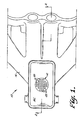
- the novel and improved fuel supply system of this . invention which is shown to include a novel and improved self-regulating heater device 12 mounted together with the usual components of an otherwise conventional automotive fuel supply system so that the heater is operable to transfer heat to an air-fuel mixture being passed through the system to an automotive engine, thereby to enhance fuel evaporation on a cold day to assure smooth engine starting and/or to reduce the emission of pollutants such as unburned hydrocarbons in the engine exhaust.
- the fuel supply system includes carburetor means 14 mounted on an intake manifold means 16 of an automotive engine 18 . for supplying an air-fuel mixture to the engine as is diagrammatically indicated in Fig.
- the heater device 12 is preferably mounted in the bottom wall 16.1 of the manifold beneath the air-fuel supply passage 14.1 of the carburetor so that the air-fuel mixture passes in heat-transfer relation to the heater device 12 as the mixture passes to the engine.
- the carburetor, intake manifold and engine means are conventional and as the heater device 12 is disposed in the fuel supply system 10 in a generally conventional location with respect to those conventional components within the scope of this invention, the conventional system components are not further described herein and it will be understood that the system 10 is adapted to supply an air-fuel mixture to the engine to meet engine requirements and the heater device 12 in the system is adapted to transfer heat to the mixture to provide a desired heating effect for improving engine starting and/or for reducing exhaust pollutant emissions from the engine.
- the novel and improved heater device 12 comprises a thermally conducting metal radiator means or body 22 or the like having a first heat-receiving side 24 and having a second, opposite, heat-transferring side 26 for transferring heat from the radiator member to a zone 27 to be heated.
- the radiator body comprises a cast unit or the like of aluminum, copper or other thermally conductive metal material having a plurality of heat-distributing rods or fins 28 or the like upstanding from the heat-transferring side of the radiator to enhance heat-transfer from the radiator to the zone 27.
- the radiator body 22 preferably includes a generally annular wall 30 extending around the heat-receiving side of the radiator to form an open-ended chamber 32.
- a flange rim or the like is provided on the wall extending around the rim of the open-chamber for use with the mounting screws 34.1 or the like in mounting the heater device 12 in electrically grounded relation to the engine 18 on the intake manifold 16 as is shown in Figs. 2 and 3.
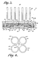
- a thin plate 35 of a thermally and electrically conducting metal material such as aluminum or the like is proportioned to fit within the chamber 32 as illustrated in Fig. 3.
- the plate is preferably formed with substantially separate , sections 35.1 which are slightly spaced from each other along a slit extending between the sections but which are maintained as intregal part of the plate by a central plate portion 35.2 having a central opening 35.3 therein.
- At least one and preferably a plurality of self-regulating heater elements36 are disposed as shown in Fig.
- a thermally and electrically conducting material 37 such as a conventional solder or silver-filled epoxy material or the like in thermally and electrically conductive relation to a first side of the plate 35 on respective sections 35.1 of the plate 35.
- the opposite side of the plate is then disposed in closely spaced, facing relation to the heat-receiving side 24 of the radiator member 22 for transferring heat from the first sides of the heater discs 36 to the radiator through the plate.
- a thin layer 39 of a thermally conducting filler material such as a conventional silicone-based grease or the like is disposed between the plate and the heat-receiving side of the radiator and screw means 35.4 are fitted through the opening 35.3 in the plate and are threadedly engaged with the radiator body for securing the plate in electrically and thermally conducting relation to the radiator, thereby to connect the first sides of the heater discs to electrical ground through the radiator.
- a thermally conducting filler material such as a conventional silicone-based grease or the like is disposed between the plate and the heat-receiving side of the radiator and screw means 35.4 are fitted through the opening 35.3 in the plate and are threadedly engaged with the radiator body for securing the plate in electrically and thermally conducting relation to the radiator, thereby to connect the first sides of the heater discs to electrical ground through the radiator.
- a terminal plate 41 has a plurality of helical coil springs 43 of a spiral configuration soldered at one end to the plate 41 as is illustrated in Fig. 3.
- the plate is mounted inside the open end of the radiator chamber 32 with the opposite ends of the springs 43 resiliently engaging the opposite sides 36.2 of the respective heater discs 36.
- An insulating ring 44 or the like is fitted around the edge of the terminal plate for electrically insulating the plate from the radiator body while a conventional retaining ring 45 is fitted into a groove 45.1 in the radiator wall 30 to hold the terminal plate in position in the radiator chamber.
- a lead 46 extending from the terminal plate through a metal heat shield 47 or the like clamped to the radiator over the terminal plate in any conventional manner, serves to connect the heater discs to a power source as will be understood.
- the heater discs are adapted to be electrically energized in electrically parallel relation to each other.
- the terminal plate 41a is further provided with portions 4l.la which are disposed in closely spaced facing relation to the heat-receiving side 24 of the radiator body.
- the entire ... , chamber 32 is then filled with a thermally conducting and electrically insulating filler material such as the silicone-based grease 39 previously described or the like whereby, as is described in the commonly assigned, copending application, Serial No.
- heat conducted from the opposite sides 36.2 of the heater discs and to the terminal plate 24a tends to be conducted through the thermally conducting filler material to the heat-receiving side 24 of the radiator body 20 for enhancing heating efficiency of the heater 12a.
- each of the heater__elements 36 is formed of a thin, disc-shaped body 36.3 of a ceramic, electrical resistance material or the like of a positive temperature coefficient of resistivity having layers of metal provided on the disc sides 36.1 and 36.2 in any conventional manner for providing ohmic electrical contact to the ceramic resistance material.
- the ceramic material comprises an yttrium-doped barium titanate material of any conventional composition having a Curie or transition temperature of 180° C. or the like above which the material displays a sharply increasing electrical resistance with increasing element temperature.
- the thermally conducting filler means 39 which is disposed in the radiator chamber 32 comprises a thermally conducting, electrically . insulating silicone-based grease or the like.
- the filler compound includes any of the various silicone materials such as dymethyl silicone or other methyl-alkyl silicones or the like which are chemically innert with respect to the ceramic materials embodied in the heater elements 36 and which are stable and preferably shaped- retaining in the temperature range from about 100°-180° C.
- Other thermally conducting electrically insulating compound such as powder materials or the like are also adapted for use in the heater device 12 within the scope of this invention.
- a conventional thermostatic switch 58 is incorporated in the noted circuit as is diagrammatically shown in Fig. 2the thermostatic switch being normally closed when the temperature of the engine 18 is below a selected temperature level but being adapted to open the circuit in response to heating of the engine to its normal operating temperature after engine warm up occurs.
- the heating device 12 and the fuel supply system 10 provide improved fuel vaporization to enhance engine starting on a cold day.
- the thermostat 58 opens the heater energizing circuit, or when the engine is subsequently stopped,the heater discs are denergized and the radiator body 20 is permitted to cool.
- the plate,35 permits some relative movement to occur between the plate 35 and the relatively massive radiator body 20 during thermal expansion and contraction, of the radiator body during such heating and cooling.
- the heater discs remain reliably bonded to the thin plate 35 during such thermal expansion contraction of the radiator body. If the . heater discs initially provide unequal heating effect, the separation of the plate 35 into substantially separate sections permits separate relative movement of the sections to further assure retention of reliable bonding between the heater discs and the plate 35.
- the heater discs are arranged to be reliably connected in electrically and thermally conducting relation to the heater body through a long service life while also serving to provide efficient heat transfer to the radiator body.
- the heater discs are also adapted to be reliably bonded to the plate 35 in a most economical manner while then permitting the plate 35 with its bonded heaters thereon to be economically mounted within the radiator body 20.
Abstract
Description
- The field of this invention is that of electrical heaters and the invention relates more particularly to self-regulating heaters having electrical resistance heater elements of a ceramic material of positive temperature coefficient of resistivity and to early fuel evaporation systems for automotive engines using such heaters.
- Early 'fuel evporattoa (EFE) systems for automotive engines have electrical heaters heating the air-fuel mixture which passes to the engine during the engine warm-up period to enhance fuel evaporation on a cold day, thereby to assure smooth engine starting or to reduce exhaust pollution emissions. Some heaters comprise thin electrical resistance heater discs of a ceramic material of positive temperature coefficient of resistivity which is adapted to display a sharp increase in resistance when the heater self-heats above a particular transition temperature such as 80°-180° C. Those heater discs are self-regulating in that they display progressively increasing electrical resistance and reduced heat output as the heater temperature increases until the heater temperature stabilizes at a safe.level.
- In certain well known EFE systems presently in commercial use, the heater includes a metal radiator body of substantial size and thermal conductivity having one heat-transferring side provided with heat-distributing rods or fins. Usually, one flat side of each of the thin ceramic heater discs is secured in electrically and thermally conducting relation to an opposite heat-receiving side of the radiator and the radiator is connected to electrical ground. Electrical terminal means engage the respective opposite sides of the heater discs for electrically connecting the resistance heater discs in parallel relation to each other. In that arrangement, the heater discs are conveniently energized from the battery or generator power source of the automotive engine when the engine is started by closing - · r of the ignition switch and are adapted to effect efficient transfer of heat to the radiator for rapidly heating the air-fuel mixture during cold weather to achieve smooth engine performance during start up while reducing emission of pollutants from the engine exhaust.
- However, it is found that, as the radiator body of the heater is subjected to thermal expansion and contraction during repeated heating and cooling of the EFE system, the electrical and thermal bond between the heater discs and the heat-receiving side of the radiator body can be broken resulting in breaking of the heater-energizing circuit. It would be desirable if an economical and effi- . cient means could be provided for electrically and thermally connecting the resistance heater discs to the radiator body and for assuring that such electrical and thermal mounting of the heater discs would be reliably maintained throughout a long service life.
- It is an object of this invention to provide a novel and improved self-renulating heater device; to provide such a heater device which is particularly adapted for use in an early fuel evaporation system for an automotive engine; to provide such a heater device which is adapted to furnish a desired heating effect with high heating efficiency; to provide such a heater device having improved reliability for use in an automotive environment; and to provide a novel and improved fuel supply system for an automotive engine utilizing such a heater device.
- Briefly described, the novel and improved self-regulating heater device of this invention as used in the novel and improved fuel supply system of this invention includes a thermally conducting metal radiator means of substantial size and thermal conductivity having a first heat-receiving side and a second, opposite side for transferring heat to a zone to be heated. Preferably, the radiator means comprises a cast body of aluminum or other thermally and electrically conductive metal material having a wall extending around the heat-receiving side of the body to form and open-ended chamber, having mounting means such as a flange extending around the rim of the chamber.wall, and having a plurality of heat-distributing rods or fins extending from the outer heat-transferring side of the cast body.
- A thin plate of a thermally and electrically conductive metal material such as aluminum or the like has a plurality of self-regulating electrical resistance heater discs of a ceramic material of positive temperature of coefficient of resistivity disposed with first disc sides bonded in electrically and thermally conducting relation to a first side of the thin plate. The opposite side of the thin plate is secured in closely spaced, facing, electrically and thermally conducting relation to the inner heat-receiving side of the radiator body. Preferably a thermally conducting filler material such as a silicone grease or the like is disposed between the thin plate and the heat-receiving side of the radiator body and screw means serve to hold the plate in closely spaced, electrically and thermally conducting relation to the radiator body. Electrical terminal means are connected to second,-opposite sides of the heater discs for electrically connecting the heater discs in parallel relation to each other to a power source.
- In a preferred embodiment of the invention, a thermally conducting metal cover member preferably formed of a thermally conducting material such as aluminum or the like is disposed in the open end of the radiator chamber for cooperating with the radiator in enclosing the heater discs in the chamber. A thermally conducting and electrically insulating filler compound such as silicone grease or the like is also enclosed in the chamber around the heater discs for facilitating the transfer of heat from the heater discs to the cover member and from the heater discs and cover member to the radiator body.
- In that arrangement, the heater device is mounted in a fuel supply system for an automobile engine to dispose the heat-transferring side of the radiator means to transfer heat to the air-fuel mixture being furnished to the engine. The radiator member is connected to electrical ground and the terminal means are connected to the power source associated with the automobile engine so that, when the engine is started, the heater discs are electrically energized in parallel relation to each other. The heater discs are easily and economically bonded in secure reliable relation to the thin plate and the plate is then secured in efficient heat-transfer relation to the heat-receiving side of the radiator body. The thin plate permits the heater discs to move relative to the larger radiator body during'thermal expansion and contraction of the radiator body as the automotive engine is started and stopped. Thus, the construction assures reliable bonding of the heater discs in thermally and electrically conductive relation to the radiator body through a long service life. Description of the Drawings
- Other objects, advantages and details of the novel and improved heaters and fuel supply systems of this invention appear in the following detailed description of preferred embodiments of the invention, the detailed description referring to the drawings in which:
- Fig. 1 is a plan view of the self-regulating heater and fuel supply system of this invention diagrammatically showing the heater mounted in an otherwise conventional fuel supply system of an automotive engine;
- Fig. 2 is a section view along line 2-2 of Fig. 1 schematically illustrating connection of the heater in an electrical circuit in an automobile;
- Fig. 3 is a partial section view similar to Fig. 2 to enlarged scale illustrating the components of the heater shown in Figs. 1 and 2; and
- Fig. 4 is a bottom plan view of a component-of the heater illustrated in Fig. 3; and
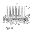
- Fig. 5 is a partial section view similar to Fig. 3 illustrating an alternate embodiment of the heater of this invention.
- Referring to the drawings, 10 in Figs. 1-4 indicates the novel and improved fuel supply system of this . , invention which is shown to include a novel and improved self-regulating heater device 12 mounted together with the usual components of an otherwise conventional automotive fuel supply system so that the heater is operable to transfer heat to an air-fuel mixture being passed through the system to an automotive engine, thereby to enhance fuel evaporation on a cold day to assure smooth engine starting and/or to reduce the emission of pollutants such as unburned hydrocarbons in the engine exhaust. In a preferred embodiment of this invention for example, the fuel supply system includes carburetor means 14 mounted on an intake manifold means 16 of an automotive engine 18 . for supplying an air-fuel mixture to the engine as is diagrammatically indicated in Fig. 2 by the arrow 20. In that arrangement, the heater device 12 is preferably mounted in the bottom wall 16.1 of the manifold beneath the air-fuel supply passage 14.1 of the carburetor so that the air-fuel mixture passes in heat-transfer relation to the heater device 12 as the mixture passes to the engine. As the carburetor, intake manifold and engine means are conventional and as the heater device 12 is disposed in the
fuel supply system 10 in a generally conventional location with respect to those conventional components within the scope of this invention, the conventional system components are not further described herein and it will be understood that thesystem 10 is adapted to supply an air-fuel mixture to the engine to meet engine requirements and the heater device 12 in the system is adapted to transfer heat to the mixture to provide a desired heating effect for improving engine starting and/or for reducing exhaust pollutant emissions from the engine. - In accordance with this invention, the novel and improved heater device 12 comprises a thermally conducting metal radiator means or
body 22 or the like having a first heat-receivingside 24 and having a second, opposite, heat-transferringside 26 for transferring heat from the radiator member to azone 27 to be heated. Preferably, the radiator body comprises a cast unit or the like of aluminum, copper or other thermally conductive metal material having a plurality of heat-distributing rods orfins 28 or the like upstanding from the heat-transferring side of the radiator to enhance heat-transfer from the radiator to thezone 27. - In a preferred embodiment of the invention, the
radiator body 22 preferably includes a generallyannular wall 30 extending around the heat-receiving side of the radiator to form an open-ended chamber 32. Preferably a flange rim or the like is provided on the wall extending around the rim of the open-chamber for use with the mounting screws 34.1 or the like in mounting the heater device 12 in electrically grounded relation to the engine 18 on theintake manifold 16 as is shown in Figs. 2 and 3. - In accordance with this invention, a
thin plate 35 of a thermally and electrically conducting metal material such as aluminum or the like is proportioned to fit within thechamber 32 as illustrated in Fig. 3. As shown in Fig. 4, the plate is preferably formed with substantially separate , sections 35.1 which are slightly spaced from each other along a slit extending between the sections but which are maintained as intregal part of the plate by a central plate portion 35.2 having a central opening 35.3 therein. At least one and preferably a plurality of self-regulating heater elements36 are disposed as shown in Fig. 3 with first sides 36.1 of the elements bonded by means of a thin layer of a thermally and electrically conductingmaterial 37 such as a conventional solder or silver-filled epoxy material or the like in thermally and electrically conductive relation to a first side of theplate 35 on respective sections 35.1 of theplate 35. The opposite side of the plate is then disposed in closely spaced, facing relation to the heat-receivingside 24 of theradiator member 22 for transferring heat from the first sides of theheater discs 36 to the radiator through the plate. Preferably athin layer 39 of a thermally conducting filler material such as a conventional silicone-based grease or the like is disposed between the plate and the heat-receiving side of the radiator and screw means 35.4 are fitted through the opening 35.3 in the plate and are threadedly engaged with the radiator body for securing the plate in electrically and thermally conducting relation to the radiator, thereby to connect the first sides of the heater discs to electrical ground through the radiator. - The opposite sides 36.2 of the heater discs are electrically connected to a power source in any conventional manner for electrically energizing the heater discs as will be understood. Preferably for example, a
terminal plate 41 has a plurality ofhelical coil springs 43 of a spiral configuration soldered at one end to theplate 41 as is illustrated in Fig. 3. The plate is mounted inside the open end of theradiator chamber 32 with the opposite ends of thesprings 43 resiliently engaging the opposite sides 36.2 of therespective heater discs 36. Aninsulating ring 44 or the like is fitted around the edge of the terminal plate for electrically insulating the plate from the radiator body while aconventional retaining ring 45 is fitted into a groove 45.1 in theradiator wall 30 to hold the terminal plate in position in the radiator chamber. Alead 46, extending from the terminal plate through ametal heat shield 47 or the like clamped to the radiator over the terminal plate in any conventional manner, serves to connect the heater discs to a power source as will be understood. In that arrangement, the heater discs are adapted to be electrically energized in electrically parallel relation to each other. - In an alternate embodiment of this invention as shown in Fig. 5, in which corresponding components are identified with corresponding reference numerals, the terminal plate 41a is further provided with portions 4l.la which are disposed in closely spaced facing relation to the heat-receiving
side 24 of the radiator body. The entire ... ,chamber 32 is then filled with a thermally conducting and electrically insulating filler material such as the silicone-basedgrease 39 previously described or the like whereby, as is described in the commonly assigned, copending application, Serial No. 210,955 filed November 28, 1980, heat conducted from the opposite sides 36.2 of the heater discs and to the terminal plate 24a tends to be conducted through the thermally conducting filler material to the heat-receivingside 24 of the radiator body 20 for enhancing heating efficiency of the heater 12a. - In preferred embodiments of this invention for example, each of the
heater__elements 36 is formed of a thin, disc-shaped body 36.3 of a ceramic, electrical resistance material or the like of a positive temperature coefficient of resistivity having layers of metal provided on the disc sides 36.1 and 36.2 in any conventional manner for providing ohmic electrical contact to the ceramic resistance material. Preferably, the ceramic material comprises an yttrium-doped barium titanate material of any conventional composition having a Curie or transition temperature of 180° C. or the like above which the material displays a sharply increasing electrical resistance with increasing element temperature. - In accordance with this invention, the thermally conducting filler means 39 which is disposed in the
radiator chamber 32 comprises a thermally conducting, electrically . insulating silicone-based grease or the like. -Preferably, the filler compound includes any of the various silicone materials such as dymethyl silicone or other methyl-alkyl silicones or the like which are chemically innert with respect to the ceramic materials embodied in theheater elements 36 and which are stable and preferably shaped- retaining in the temperature range from about 100°-180° C. Other thermally conducting electrically insulating compound such as powder materials or the like are also adapted for use in the heater device 12 within the scope of this invention. - In that construction,.mounting of the heater device 12 for example on the
intake manifold 16 as shown in Figs. 2 and 3 disposes the heat-transferringside 26 of theradiator member 22 in heat-transfer relation to thezone 27 within the manifold. That mounting also serves to electrically ground theradiator member 22 to the engine, as is diagrammatically indicated 52 in Fig. 2. Accordingly, theterminal connector 46 on the heater device is easily connected through theignition switch 54 or the like to the battery, generator or other power source means of the automobile engine diagrammatically indicated at 56 so that theheater elements 36 are electrically energized in parallel relation to each other whenever operation of the engine 18 is initiated. If desired, a conventional thermostatic switch 58 is incorporated in the noted circuit as is diagrammatically shown in Fig. 2the thermostatic switch being normally closed when the temperature of the engine 18 is below a selected temperature level but being adapted to open the circuit in response to heating of the engine to its normal operating temperature after engine warm up occurs. - In that arrangement, when the
heater elements 36 are first energized as operation of the engine 18 is initiated on a cold day, heat which is generated in theceramic heater discs 36 is efficiently transferred through theplate 35 and thefiller material 39 to the radiator body 20. As a result, the heating device 12 and thefuel supply system 10 provide improved fuel vaporization to enhance engine starting on a cold day. When the engine warms up so that the thermostat 58 opens the heater energizing circuit, or when the engine is subsequently stopped,the heater discs are denergized and the radiator body 20 is permitted to cool. In the heater device of this invention, the plate,35 permits some relative movement to occur between theplate 35 and the relatively massive radiator body 20 during thermal expansion and contraction, of the radiator body during such heating and cooling. Accordingly, the heater discs remain reliably bonded to thethin plate 35 during such thermal expansion contraction of the radiator body. If the . heater discs initially provide unequal heating effect, the separation of theplate 35 into substantially separate sections permits separate relative movement of the sections to further assure retention of reliable bonding between the heater discs and theplate 35. In that construction, the heater discs are arranged to be reliably connected in electrically and thermally conducting relation to the heater body through a long service life while also serving to provide efficient heat transfer to the radiator body. The heater discs are also adapted to be reliably bonded to theplate 35 in a most economical manner while then permitting theplate 35 with its bonded heaters thereon to be economically mounted within the radiator body 20. - It should be understood that although particular embodiments of the heater device and fuel supply system of this invention have been described above by way of illustrating the invention, many modifications of the described embo- dimens are possible within the scope of the invention.
Claims (10)
Applications Claiming Priority (2)
| Application Number | Priority Date | Filing Date | Title |
|---|---|---|---|
| US06/248,773 US4419564A (en) | 1981-03-30 | 1981-03-30 | Self-regulating electric heater for use in an early fuel evaporation system |
| US248773 | 1994-05-25 |
Publications (3)
| Publication Number | Publication Date |
|---|---|
| EP0061848A1 true EP0061848A1 (en) | 1982-10-06 |
| EP0061848B1 EP0061848B1 (en) | 1986-02-05 |
| EP0061848B2 EP0061848B2 (en) | 1990-01-24 |
Family
ID=22940621
Family Applications (1)
| Application Number | Title | Priority Date | Filing Date |
|---|---|---|---|
| EP82301174A Expired - Lifetime EP0061848B2 (en) | 1981-03-30 | 1982-03-08 | Fuel heater system and self-regulating heater |
Country Status (3)
| Country | Link |
|---|---|
| US (1) | US4419564A (en) |
| EP (1) | EP0061848B2 (en) |
| DE (1) | DE3268912D1 (en) |
Cited By (5)
| Publication number | Priority date | Publication date | Assignee | Title |
|---|---|---|---|---|
| DE3320903A1 (en) * | 1983-06-09 | 1985-02-28 | Bayerische Motoren Werke AG, 8000 München | Heating device for fuel of internal combustion engines |
| DE3805927A1 (en) * | 1988-02-25 | 1989-08-31 | Bosch Gmbh Robert | DEVICE FOR IMPROVING THE MIXTURE DISTRIBUTION |
| DE3936088A1 (en) * | 1989-01-02 | 1990-07-05 | Weinert E Messgeraetewerk | Self-regulating electric heating device - has contact element acting on heating elements pressed against heating block |
| EP0453927A1 (en) * | 1990-04-17 | 1991-10-30 | Texas Instruments Holland B.V. | Injection internal combustion engine with electric spark ignition |
| GB2338987A (en) * | 1998-06-30 | 2000-01-12 | Cummins Engine Co Ltd | I.c. engine intake air system with electric heater inside manifold |
Families Citing this family (15)
| Publication number | Priority date | Publication date | Assignee | Title |
|---|---|---|---|---|
| JPH0234457Y2 (en) * | 1984-09-27 | 1990-09-17 | ||
| NL8602782A (en) * | 1986-11-03 | 1988-06-01 | Texas Instruments Holland | COMBUSTION ENGINE. |
| NL8700430A (en) * | 1987-02-20 | 1988-09-16 | Texas Instruments Holland | HEATING DEVICE FOR FUEL, IN PARTICULAR DIESEL OIL. |
| US4898668A (en) * | 1988-09-30 | 1990-02-06 | Stanadyne Automotive Corp. | Fuel filter with heater |
| DE4014104A1 (en) * | 1990-05-02 | 1991-11-14 | Draloric Electronic | ELECTRICAL POWER RESISTANCE |
| JPH0571434A (en) * | 1991-09-12 | 1993-03-23 | Nissan Motor Co Ltd | Injection fuel heating device for internal combustion engine |
| JPH08241802A (en) | 1995-03-03 | 1996-09-17 | Murata Mfg Co Ltd | Thermistor device and manufacture thereof |
| DE19846282B4 (en) * | 1998-10-08 | 2006-12-07 | Mann + Hummel Gmbh | Electric heater |
| DE10102671C2 (en) * | 2001-01-17 | 2003-12-24 | Eichenauer Heizelemente Gmbh | Electric heating for a motor vehicle |
| DE10208103A1 (en) * | 2002-02-26 | 2003-09-11 | Beru Ag | Electric air heating device, in particular for a motor vehicle |
| DE10325965B4 (en) * | 2003-06-07 | 2007-01-11 | Mann + Hummel Gmbh | Heating device for fluids |
| US7614388B2 (en) * | 2005-05-09 | 2009-11-10 | Phillips & Temro Industries Inc. | Flanged heating element with thermal expansion joint |
| US7230215B2 (en) * | 2005-08-26 | 2007-06-12 | Cheng Ping Lin | Heat generating device formed of heat generating diaphragm plates |
| DE102010004612A1 (en) * | 2010-01-13 | 2011-07-14 | Emitec Gesellschaft für Emissionstechnologie mbH, 53797 | Device with a tank and a delivery unit for reducing agent |
| EP2827977A4 (en) * | 2012-03-23 | 2015-11-25 | Intelligent Energy Ltd | Hydrogen producing fuel cartridge and methods for producing hydrogen |
Citations (7)
| Publication number | Priority date | Publication date | Assignee | Title |
|---|---|---|---|---|
| FR2209047A1 (en) * | 1972-12-05 | 1974-06-28 | Texas Instruments Inc | |
| US3976854A (en) * | 1974-07-31 | 1976-08-24 | Matsushita Electric Industrial Co., Ltd. | Constant-temperature heater |
| FR2307430A1 (en) * | 1975-04-07 | 1976-11-05 | Philips Nv | SELF-REGULATING HEATING ELEMENT |
| US3996447A (en) * | 1974-11-29 | 1976-12-07 | Texas Instruments Incorporated | PTC resistance heater |
| US4242999A (en) * | 1976-07-01 | 1981-01-06 | Alfred Hoser | Self-regulating heater |
| US4246880A (en) * | 1978-08-23 | 1981-01-27 | Pierburg Gmbh & Co. Kg | Arrangement for heating the intake pipe of a spark-ignited internal combustion engine |
| DE3030812A1 (en) * | 1979-08-17 | 1981-02-26 | Nippon Soken | FUEL EVAPORATOR |
Family Cites Families (6)
| Publication number | Priority date | Publication date | Assignee | Title |
|---|---|---|---|---|
| US3748439A (en) * | 1971-12-27 | 1973-07-24 | Texas Instruments Inc | Heating apparatus |
| US3995141A (en) * | 1975-10-31 | 1976-11-30 | Texas Instruments Incorporated | Food warming device |
| US4121088A (en) * | 1976-10-18 | 1978-10-17 | Rosemount Inc. | Electrically heated air data sensing device |
| US4325344A (en) * | 1979-06-05 | 1982-04-20 | Nippon Soken, Inc. | Fuel evaporator |
| JPS5663790A (en) * | 1979-10-26 | 1981-05-30 | Nippon Soken | Ceramic heater |
| JPS5922280Y2 (en) * | 1979-10-31 | 1984-07-03 | 株式会社日本自動車部品総合研究所 | Internal combustion engine intake air heating device |
-
1981
- 1981-03-30 US US06/248,773 patent/US4419564A/en not_active Expired - Fee Related
-
1982
- 1982-03-08 EP EP82301174A patent/EP0061848B2/en not_active Expired - Lifetime
- 1982-03-08 DE DE8282301174T patent/DE3268912D1/en not_active Expired
Patent Citations (7)
| Publication number | Priority date | Publication date | Assignee | Title |
|---|---|---|---|---|
| FR2209047A1 (en) * | 1972-12-05 | 1974-06-28 | Texas Instruments Inc | |
| US3976854A (en) * | 1974-07-31 | 1976-08-24 | Matsushita Electric Industrial Co., Ltd. | Constant-temperature heater |
| US3996447A (en) * | 1974-11-29 | 1976-12-07 | Texas Instruments Incorporated | PTC resistance heater |
| FR2307430A1 (en) * | 1975-04-07 | 1976-11-05 | Philips Nv | SELF-REGULATING HEATING ELEMENT |
| US4242999A (en) * | 1976-07-01 | 1981-01-06 | Alfred Hoser | Self-regulating heater |
| US4246880A (en) * | 1978-08-23 | 1981-01-27 | Pierburg Gmbh & Co. Kg | Arrangement for heating the intake pipe of a spark-ignited internal combustion engine |
| DE3030812A1 (en) * | 1979-08-17 | 1981-02-26 | Nippon Soken | FUEL EVAPORATOR |
Cited By (7)
| Publication number | Priority date | Publication date | Assignee | Title |
|---|---|---|---|---|
| DE3320903A1 (en) * | 1983-06-09 | 1985-02-28 | Bayerische Motoren Werke AG, 8000 München | Heating device for fuel of internal combustion engines |
| DE3805927A1 (en) * | 1988-02-25 | 1989-08-31 | Bosch Gmbh Robert | DEVICE FOR IMPROVING THE MIXTURE DISTRIBUTION |
| DE3936088A1 (en) * | 1989-01-02 | 1990-07-05 | Weinert E Messgeraetewerk | Self-regulating electric heating device - has contact element acting on heating elements pressed against heating block |
| EP0453927A1 (en) * | 1990-04-17 | 1991-10-30 | Texas Instruments Holland B.V. | Injection internal combustion engine with electric spark ignition |
| US5172673A (en) * | 1990-04-17 | 1992-12-22 | Texas Instruments Incorporated | Injection internal combustion engine with electrical spark ignition |
| GB2338987A (en) * | 1998-06-30 | 2000-01-12 | Cummins Engine Co Ltd | I.c. engine intake air system with electric heater inside manifold |
| US6325053B1 (en) | 1998-06-30 | 2001-12-04 | Cummins Engine Company Ltd. | Intake system for an internal combustion engine |
Also Published As
| Publication number | Publication date |
|---|---|
| EP0061848B2 (en) | 1990-01-24 |
| EP0061848B1 (en) | 1986-02-05 |
| US4419564A (en) | 1983-12-06 |
| DE3268912D1 (en) | 1986-03-20 |
Similar Documents
| Publication | Publication Date | Title |
|---|---|---|
| US4419564A (en) | Self-regulating electric heater for use in an early fuel evaporation system | |
| US4387291A (en) | Fuel heater system and self-regulating heater therefor | |
| US3806854A (en) | Control for automotive choke | |
| US3699937A (en) | Solid state controlled automatic choke | |
| JP2502945B2 (en) | Injection internal combustion engine | |
| JPH06123498A (en) | Heater | |
| US4327697A (en) | Heater for air-fuel mixture having heating element of positive temperature coefficient resistor | |
| EP0582428A1 (en) | Heating device and system for the internal combustion engine | |
| JPS5939167Y2 (en) | Internal combustion engine intake air heating device | |
| JPS61185676A (en) | Heating device for vehicle | |
| US4237077A (en) | Automatic choke system | |
| EP0051925B1 (en) | Fuel supply system with automatic choke | |
| US4496496A (en) | Fuel supply system with electric choke and control therefor | |
| JPS59101572A (en) | Low-temperature starter for car | |
| US4463737A (en) | Fuel system having gasket heater | |
| US4465053A (en) | Fuel system having low profile gasket heater | |
| US4467773A (en) | Fuel supply system with improved throttle body heater | |
| JPH0625613Y2 (en) | Oil heater | |
| JPS6316114A (en) | Heating device for engine oil | |
| JPS6126625Y2 (en) | ||
| JPS6329174Y2 (en) | ||
| RU2140546C1 (en) | Device for facilitating starting of internal combustion engine by electric starter | |
| JPH036848Y2 (en) | ||
| JPH07158510A (en) | Spark ignition type engine with auto choke | |
| RU2072439C1 (en) | Engine electric preheater |
Legal Events
| Date | Code | Title | Description |
|---|---|---|---|
| PUAI | Public reference made under article 153(3) epc to a published international application that has entered the european phase |
Free format text: ORIGINAL CODE: 0009012 |
|
| AK | Designated contracting states |
Designated state(s): DE FR GB IT NL |
|
| 17P | Request for examination filed |
Effective date: 19830405 |
|
| GRAA | (expected) grant |
Free format text: ORIGINAL CODE: 0009210 |
|
| ITF | It: translation for a ep patent filed |
Owner name: BARZANO' E ZANARDO ROMA S.P.A. |
|
| AK | Designated contracting states |
Designated state(s): DE FR GB IT NL |
|
| REF | Corresponds to: |
Ref document number: 3268912 Country of ref document: DE Date of ref document: 19860320 |
|
| ET | Fr: translation filed | ||
| PLBI | Opposition filed |
Free format text: ORIGINAL CODE: 0009260 |
|
| 26 | Opposition filed |
Opponent name: SIEMENS AKTIENGESELLSCHAFT, BERLIN UND MUENCHEN Effective date: 19861031 |
|
| NLR1 | Nl: opposition has been filed with the epo |
Opponent name: SIEMENS AKTIENGESELLSCHAFT |
|
| ITF | It: translation for a ep patent filed |
Owner name: BARZANO' E ZANARDO ROMA S.P.A. |
|
| PUAH | Patent maintained in amended form |
Free format text: ORIGINAL CODE: 0009272 |
|
| STAA | Information on the status of an ep patent application or granted ep patent |
Free format text: STATUS: PATENT MAINTAINED AS AMENDED |
|
| 27A | Patent maintained in amended form |
Effective date: 19900124 |
|
| AK | Designated contracting states |
Kind code of ref document: B2 Designated state(s): DE FR GB IT NL |
|
| NLR2 | Nl: decision of opposition | ||
| ET1 | Fr: translation filed ** revision of the translation of the patent or the claims | ||
| NLR3 | Nl: receipt of modified translations in the netherlands language after an opposition procedure | ||
| EN3 | Fr: translation not filed ** decision concerning opposition | ||
| ET | Fr: translation filed |
Free format text: BO 90/24 PAGE 181: ANNULATION |
|
| ET | Fr: translation filed |
Free format text: BO 24/90 PAGE 181: ANNULATION |
|
| ET3 | Fr: translation filed ** decision concerning opposition | ||
| PGFP | Annual fee paid to national office [announced via postgrant information from national office to epo] |
Ref country code: FR Payment date: 19950314 Year of fee payment: 14 |
|
| PGFP | Annual fee paid to national office [announced via postgrant information from national office to epo] |
Ref country code: NL Payment date: 19950331 Year of fee payment: 14 |
|
| PGFP | Annual fee paid to national office [announced via postgrant information from national office to epo] |
Ref country code: DE Payment date: 19950411 Year of fee payment: 14 |
|
| PG25 | Lapsed in a contracting state [announced via postgrant information from national office to epo] |
Ref country code: NL Effective date: 19961001 |
|
| PG25 | Lapsed in a contracting state [announced via postgrant information from national office to epo] |
Ref country code: FR Effective date: 19961129 |
|
| NLV4 | Nl: lapsed or anulled due to non-payment of the annual fee |
Effective date: 19961001 |
|
| PG25 | Lapsed in a contracting state [announced via postgrant information from national office to epo] |
Ref country code: DE Effective date: 19961203 |
|
| REG | Reference to a national code |
Ref country code: FR Ref legal event code: ST |
|
| PGFP | Annual fee paid to national office [announced via postgrant information from national office to epo] |
Ref country code: GB Payment date: 20000308 Year of fee payment: 19 |
|
| PG25 | Lapsed in a contracting state [announced via postgrant information from national office to epo] |
Ref country code: GB Free format text: LAPSE BECAUSE OF NON-PAYMENT OF DUE FEES Effective date: 20010308 |
|
| GBPC | Gb: european patent ceased through non-payment of renewal fee |
Effective date: 20010308 |