EP0061832A2 - Apparatus and method for checking identity by means of the ocular fundus pattern - Google Patents
Apparatus and method for checking identity by means of the ocular fundus pattern Download PDFInfo
- Publication number
- EP0061832A2 EP0061832A2 EP82300782A EP82300782A EP0061832A2 EP 0061832 A2 EP0061832 A2 EP 0061832A2 EP 82300782 A EP82300782 A EP 82300782A EP 82300782 A EP82300782 A EP 82300782A EP 0061832 A2 EP0061832 A2 EP 0061832A2
- Authority
- EP
- European Patent Office
- Prior art keywords
- light
- eye
- source
- fixation
- reflected
- Prior art date
- Legal status (The legal status is an assumption and is not a legal conclusion. Google has not performed a legal analysis and makes no representation as to the accuracy of the status listed.)
- Granted
Links
Images


Classifications
-
- A—HUMAN NECESSITIES
- A61—MEDICAL OR VETERINARY SCIENCE; HYGIENE
- A61B—DIAGNOSIS; SURGERY; IDENTIFICATION
- A61B3/00—Apparatus for testing the eyes; Instruments for examining the eyes
- A61B3/10—Objective types, i.e. instruments for examining the eyes independent of the patients' perceptions or reactions
- A61B3/12—Objective types, i.e. instruments for examining the eyes independent of the patients' perceptions or reactions for looking at the eye fundus, e.g. ophthalmoscopes
-
- A—HUMAN NECESSITIES
- A61—MEDICAL OR VETERINARY SCIENCE; HYGIENE
- A61B—DIAGNOSIS; SURGERY; IDENTIFICATION
- A61B5/00—Measuring for diagnostic purposes; Identification of persons
- A61B5/117—Identification of persons
- A61B5/1171—Identification of persons based on the shapes or appearances of their bodies or parts thereof
-
- G—PHYSICS
- G06—COMPUTING; CALCULATING OR COUNTING
- G06V—IMAGE OR VIDEO RECOGNITION OR UNDERSTANDING
- G06V40/00—Recognition of biometric, human-related or animal-related patterns in image or video data
- G06V40/10—Human or animal bodies, e.g. vehicle occupants or pedestrians; Body parts, e.g. hands
- G06V40/18—Eye characteristics, e.g. of the iris
- G06V40/19—Sensors therefor
Definitions
- This invention relates to apparatus and method for recognizing an individual and/or for verifying an individual's identity. It pertains particularly to such apparatus and method which records for comparison a unique and repeatable electronic identification pattern of an individual's unique ocular structure.
- Prior art methods of verification include photographs, fingerprints, signatures, voice prints, or presentation of an identification number, either by the person or by a magnetic strip on a card.
- U.S. No. 4,109,237 discloses a basic method and apparatus for identifying individuals through their retinal vasculature patterns.
- the apparatus therein discussed includes a plurality of light sources arranged in dual concentric circles. The light sources are sequentially illuminated and darkened, providing a flying spot light source. Green light is used so that it is substantially absorbed by the dark red blood vessels and substantially reflected by the retinal tissue.
- the present invention overcomes the above disadvantages and is an improvement over that disclosed in my previous patent.
- the present invention is an apparatus and method for obtaining and recording an identification pattern from the structure of the fundus of an eye.
- a single light source operable to produce a substantially columnar beam of light
- a means for directing at least a portion of the beam into the eye from various sequential, angularly divergent positions means for detecting the amount of light reflected from the eye at each angularly divergent position, and means for recording the amounts of light thus sensed.
- the person to be identified places his eye in the columnar source beam of light.
- the beam is directed into the eye from various angularly divergent positions, the light substantially focusing on- the retina-and being reflected in part out of the eye.
- the amounts of light thus reflected are sensed and recorded, forming an individual identification pattern.
- the hereindescribed identification apparatus and method takes advantage of the fact that of all human physiological features, the image of the structure of the fundus of the eye is the best identifying characteristic ⁇ . This- is for the reason that each such retinal image is unique to the individual. It is particularly unique in the number of major retinal blood vessels in the area of the optic disk and the relative angles and branching characteristics of these vessels as they emerge from the optic nerve. Further substantially stable features of the fundus of the eye include the size of the optic disk, pigments or coloring patterns of the retina, and the choroidal vasculature.
- the retina of the eye is anatomically and physiologically a part of, and an extension of, the brain which nature has provided with the highest precision biofeedback system for environmental control. This remains intact and effective throughout life, even in the presence of bodily trauma, disease and stress.
- the retinal image is impossible to counterfeit. Further, because the identifying characteristic involves the subject's function of seeing, changing the retinal image is impossible. Still further, because of relatively simple optical access, the retinal image is easy to acquire. Focusing of the eye aids in its acquisition. The eye provides much of the optics required to obtain the image.
- retinal images are easily susceptible to automated acquisition. No subjective interpretation of the data need be made. The number of variables is small, making the identification process simple and reliable to a machine.
- the method of the present invention broadly comprises digital acquisition of the reflectance pattern of the back inside of the eye for the purpose of providing the data by which a digital computer can identify individuals.
- the method for obtaining the pattern comprises first causing the person's eye to become fixated and positioned by fixation and positioning means.
- the eye is indexed relative to a fixation target and positioned both horizontally and vertically_to a precise degree and axially to a less precise degree relative to the cornea of the eye being scanned.
- This procedure causes a particular section of the eye to be presented in order to obtain a repeatable pattern and assures that the entire scan beam enters the pupil.
- the eye is fixated and positioned, it is scanned with an infrared light source which is arranged in a selected pattern determined efficiently to intercept the major contrasting features. These features are largely comprised of the major vessels and especially the veins contrasted with the surrounding tissue.
- the reflected portion of the light is detected, filtered, converted to digital form, stored in computer memory and sent to a host computer as reference data or to be matched with reference data acquired earlier.
- the identification apparatus of the invention is mounted in an easily accessible location at an identification check point, for instance a funds transfer machine or a security entrance, as illustrated at 22. It comprises a case 24, which encloses the hereinafter described optics, and a mounting bracket 26 which supports-the apparatus-at- a convenient position for-the user.
- a head bracing means such as a light shield or head support 28 is provided to position the user correctly for looking into the instrument.
- a knob 30 controls the interpupillary distance and another dial or lens turret 32 controls focus.
- a trigger or button 34 is operable by the user to initiate the identification sequence.
- Figs. 2 and 3 show a diagrammatic representation of an eyeball 36 having beams 38 and 38' entering therein.
- the anterior portion of the eye includes a cornea 40, and behind the cornea an iris 42 having a pupil 44 as its central opening.
- a lens 46 is located behind the iris supported by muscles 48 which, by expanding or contracting, may vary the focus of the lens.
- the posterior or fundus portion of eyeball 36 includes a retina 50, which is the light sensitive tissue of the eye, and other supporting structures.
- the most light sensitive portion of the retina is the fovea 52 which is directly on the axis of the eye and is very densely packed with the light receptor structures, i.e. the rods and cones (not shown).
- the optic disk 56 In the central portion of the optic disk is a slight depression or cup 58.
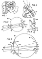
- the central blood vessels 60 need not enter at exactly the center of optic disk 56, as is evident in Fig. 6. However, upon entry the blood vessels rapidly branch into a plurality of smaller vessels which extend somewhat randomly throughout the retina. Generally, no large blood vessels are found in the area of fovea 52 which is off the left side of the drawing of Fig. 6. This retinal vasculature is a very stable congenital structure and is unique to each individual, providing a definitive identification pattern.
- Figs. 2 and 3 show a columnated beam of light 38 directed into the eye.
- the eye is focused on infinity, and thus all'rays in the column are focused to a small spot on retina 50.
- the entering beam is operable to move in a cone having its apex at the lens of the eye, and thus enters the eye from a circle of sequential angularly divergent positions such as is shown at 38'.
- a locus of points is illuminated en the retina, as is illustrated by the dashed circle 64.
- Fig. 4 is an enlarged view of retina 50 showing a segment of the locus 64.
- One of the blood vessels 62' extends across this area of the retina and is intersected by the locus of sequentially illuminated points. As shown by the arrows, light striking the retina is reflected, while light striking the'darker blood vessel is substantially absorbed.
- a circular scale shown at 66, is used in the practice of the invention.
- the circular scale is graduated in 256 divisions, each representing a location where the intensity of light reflected back from the fundus of the eye is measured.
- Locus 64 conforms to the dashed circle, and in Fig. 7 a dark bar 68 is shown where the reflected intensity is low due to absorption of the light by a blood vessel.
- a graph 70 illustrates the absorption as smoothed over the 256 points. Some background noise is evident in the measured intensities. However, major changes in the reflected intensity are a result of readily observable structures in the eye.
- the apparatus of the present invention is shown in a first embodiment in Figs. 8 and 9. While the scanning of a single eye is adequate for purposes of obtaining a unique identification pattern, the apparatus is preferably binocular, as illustrated. This aids particularly in repeatably stabilizing the orientation and fixation of the eyes, as well as allowing use by individuals who can see only in one eye.
- Fig. 8 shows a top view of the apparatus, including two halves which are essentially inverse duplicates of each other.
- the apparatus is mounted on a center pedestal 72 attached to mounting bracket 26 and through which extends an interpupillary adjustment screw-.74 and a pair of guide pins 76.
- Adjustment knobs 30 are attached to the ends of the adjustment screw.
- Screw blocks 80 are threaded on the adjustment screw, one with a right hand thread and one with a left hand thread so that they will move inwardly oroutwardly together as the adjustment screw is turned.
- Each screw block is fixed to a plate 82 which in turn mounts the hereinafter described optics.
- Interpupillary adjustment screw 74 thus provides a means operable to adjust the distance between the beams to accommodate various users.
- the fixation optics includes, for each eye, a fixation reticle 84, illuminating means for illuminating the fixation reticle, preferably a light emitting diode 86, and a colum-88 nating means/for columnating the light from the light-emitting diode.
- the fixation reticles each include a pattern. Although the reticles may have an identical appearance, preferably a complete crosshair pattern-, the patterns illustrated-in Fig. 9 are complementary, wherein one reticles pattern is one half of a crosshair pattern 84' and the other reticle pattern is the other half of the crosshair pattern 84'.
- Each eye 36 can focus straight ahead on the images 84' of the fixation reticles. Because the light is columnated, the images appear at infinity, and because the beams are parallel the eyes assume a naturally relaxed position.
- a pair of lens turrets 32 is mounted on the front of the identification apparatus for individual adjustment by each user.
- Each lens turret houses a plurality of refraction correction lenses 92.
- Each lens in each turret has a different refractive power so a wide range of corrections is available.
- the turrets are mounted at an angle with re'spect to the fixation axis, the purpose of which will be discussed hereinafter.
- Figs. 8 and 9 also illustrate, in each half of the apparatus,'a motor 94 which drives a belt 96 which in turn rotates a prism journal 98.
- An encoder 100 is attached to the motor for determining its rotational position and consequently the rotational position of the prism journal.
- the beam directing optics of the present invention for driving beam 38 in a substantially circular or conical pattern, as discussed above, are best shown in a first embodiment in Figs. 10 and 11.
- Fig. 11 shows the beam rotating components of the system.
- a light source preferably an incandescent tungsten filament 102, produces a broad spectrum of light, part of which is in the near infrared range from 7500 to 9500 Angstrom units of'wavelength.
- An infrared filter 104 allows only this infrared radiation to pass further into the system.
- a lens 106 then focuses the light through a source pinhole 108 which intercepts all unwanted rays and leaves only a clearly defined spot to be transmitted into a columnating lens 110.
- the resultant column of light is then reflected off of a partially silvered mirror 112 and through a rotating prism 114 mounted in prism journal 98.
- the beam is then reflected by mirror 116 through one of lenses 92 in lens turret 32 and into the user's eyeball 36.
- the beam passes through rotating prism 114 it is deflected a small amount, preferably about 4.5 degrees.Thus, as the prism rotates, the resultant beam describes an outwardly divergent cone. However, the diverging beams coincide for some distance and form an inner cone having its apex spaced apart from the prism. The rays passing through this apex come through a single spot on the outside edge of the prism. As the prism is rotated, so also is this spot.
- the eyeball 36 of the user is presented in this inner cone of coincident beams at such a point that the size of a section of the cone substantially coincides with the size of pupil 44.
- a single spot on the perimeter of.the prism is responsible for refracting light into the eye from a plurality of sequential, angularly divergent positions.
- the remainder of the rotating prism may be blackened to eliminate the peripheral light which would be directed onto the white of the eyeball and the face of the user if the prism were all transparent.
- the diverging rays in the beams are illustrated for purposes of explanation only.
- the beams of light are columnar.
- a means for correcting the user's vision such as refraction lens 92, is required.
- the user does not wear spectacles when using this apparatus since they would induce refractive variation as a result of variation in spectacle/corneal orientation, and would tend to cause unwanted reflections.
- similar restrictions do not apply to contact lenses since they mold to cornea 40.
- 'Lens 92 varies the beam from columnar a slight amount so that the beam will be focused on the retina and thus provide vision correction.
- the small spot on retina 50 upon which the light strikes then reflects a portion of the light randomly back into the interior of eyeball 36.
- the reflected intensity depends on the type of structure encountered. The rods and cones tend to be quite reflective, while blood vessels 62 absorb much of the incident light.
- Part of the reflected light is directed toward lens 46 of the eye. This light then follows the reverse path of incoming source beam 38. It is columnated by the lens of the eye to form a reflected beam coincident with the source beam and then travels through corrector lens 92, reflects off mirror 116, and is bent slightly back to a parallel optical axis as it passes through prism 114. A portion of the reflected beam is transmitted through partially silvered mirror 112 and is thus separated from the source beam.
- the separated portion of the reflected beam is then focused by a focusing lens 118, reflected by a mirror 120 and directed through a receiver pinhole 122.
- the pinhole blocks stray light which might originate from reflections from surfaces other than the illuminated spot in the eye.
- the light is refocused by a lens 124 onto a detector 126.
- the detector senses the amount or intensity of light in the reflected beam.
- Fig. 10 illustrates the relationship between the main or scanner optical axis and the fixation optical axis.
- the fixation optics are mounted at between 14 and 17 degrees, and preferably at approximately 15.5 degrees from the scanner optical axis or the axis around which the source beam is angularly divergent.
- Eyeball 36 is oriented so that the image of fixation reticle 84 is focused at fovea 52.
- the source beam enters the eye obliquely with the scanner axis intersecting the center of optic disk 56.
- Lens 92 is oriented to bisect the angle between the fixation axis and the scanner axis so that both beams encounter similar refraction in the lens and reflections from the surfaces of the lens do not create unwanted optical noise.
- Figs. 12 and 13 illustrate a second embodiment of the optics of the present invention.
- the components of the system are substantially the same, with the exception of the apparatus and manner of compensating for refraction correction for various users.' This correction is accomplished without the need for a refraction lens 92 as previously described.
- the fixation beam is reflected by a prism 128 so that the initial fixation axis is parallel to the scanner axis.
- the fixation reticle 84 and source 86, as well as scanner source 102, filter 104, lens 106 and pinhole 108, and the detector 126, lens 124, and pinhole 122 are all mounted on a carriage 130.
- the carriage is operable to move back and forth parallel to the optical axes.
- the distance between reticle 84 and lens 88 is the same as the distance between pinhole 122 and lens 118, and pinhole 108 and lens 110.
- the resultant beam is not columnated, but varies slightly from columnar at the right amount to correct the vision of the user. Further, as the user fixates on the fixation pattern, adjusting the carriage so that the pattern is in focus also focuses the scanner optics.
- Figs. 14 and 15 illustrate a third embodiment of the optics of the present invention.
- the beam directing means comprises a rotating mirror 132 mounted in the light path in place of rotating prism 114.
- the mirror is mounted on a shaft 134 and rotated by motor 94'.
- the mirror is not normal to the shaft, rather it is preferably tilted approximately 2.25 degrees from normal. This will cause the light to be reflected in an outwardly diverging cone as the mirror is rotated.
- the diverging reflected beams coincide for some distance forming an inner cone having its apex spaced apart from the rotating mirror. And, as with the prism, only a single spot on the mirror is utilized in reflecting the source beam 38 into the eye. The remainder of the mirror may be blackened to prevent unwanted reflections.
- a shaft encoder 100' is attached to motor 94' to determine the rotational. position of the motor and thus the direction of the beam of light 38 reflected from the mirror.
- rotating mirror 132 in fact does not produce an exact circle of reflected beams. Because it is at an angle with respect to the incident beam, it rather produces an oval pattern. However, this pattern is constant or reproducible from use to use, so no error is introduced by it.
- Fi g . 5 illustrates, in schematic form, the electronics of the present invention.
- Detector/amplifier 126 produces an electric analog signal S 1 corresponding to the intensity of light striking the detector.
- An analog to digtal converter 136 receives this signal and produces a digital output data signal S 2 corresponding to the analog input signal.
- Signals S 3 and S 4 are produced by encoder 100.
- Signal S 3 is a strobe signal, pulsing once for each of the 256 positions shown by scale 66.
- Signal S 4 is a start strobe, pulsing once at a point corresponding to the zero point on the scale.
- a digital computer 138 receives the signals S 2 from the converter 136, and S 4 from the encoder 100.
- a return start or "on” signal S 5 is produced by the computer and is directed to the converter.
- the computer produces an on/off signal S 6 to control light sources 86 and 102 and motor 94.
- the final output is electric signal S 7 .
- the corrector setting for each eye is accomplished in the following manner: He sets one turret to occlude the fixation target for its corresponding eye and sets the other turret for its most far sighted (positive diopter) correction. If the fixation target presented to the non-occluded eye is out of focus, he starts to step the turret for that eye toward the most near sighted position (most negative diopter). When the target first comes into focus, he stops stepping the turret and notes the number appearing on the turret for that eye. He then repeats this procedure for the other eye.
- the user now adjusts the interpupilary distance by manipulating knob 30 to achieve the appropriate distance between the two fixation optics axes.
- the user adjusts the distance between the device eyepieces to match his inter- pupillary distance.
- this adjustment is made in the following manner: The user peers into the device and adjusts the inter-pupillary knob 30 until the two defocused images are intersected by the vertical line of the reticles 84.
- the user notes the calibration number appearing on the knob 30 and thereafter simply sets the appropriate pupil-distance number before peering into the apparatus.
- the user tilts his head until the defocused red half discs are adjacent, forming what appears to be a single defocused disc illuminating the crosshair reticle image.
- the encoder start or zero signal S 4 pulses once per complete revolution of scanning beam 38.
- the start signal is coordinated with the beam focusing on the side of the scan locus closest to fovea 52. This area is the least likely to have major blood vessels and consequently the encounters with most of the light-abosrbing structures will be centrally located in the scan sequence.
- the computer 138 upon receiving the start signal S 4 from encoder 100, produces a start or "on" signal S 5 which instructs converter 136 to begin sending digital data S 2 to the computer.
- the encoder generates a strobe signal S 3 , pulsing once for each data point to be sampled. On each pulse the converter converts the instantaneous analog voltage S l to a digital equivalent and sends it to the computer. This occurs-in rapid succession for each of the 256 points. Then the encoder pulses signal S 4 again, terminating the data stream.
- a similar procedure is either simultaneously or sequentially carried out for the other eye, and the two patterns thus obtained are combined into a single identification pattern.
- the user's identification pattern may be compared with a reference pattern or a plurality of reference patterns to determine or verify the identity of the user.
- This comparison process may best be performed by programmed general purpose digital computers having mass storage containing the recorded identification patterns of many users.
- the ocular vasculature patterns of all individuals of known identity authorized to use the system need to be entered into the data storage area. This involves an initial registration of each user in which the pattern is merely recorded, becoming the reference pattern for later recall and use.
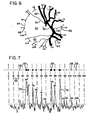
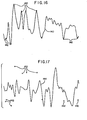
- Fig. 16 illustrates the waveform 140 representing the retinal pattern of an eye of one . individual, with the rectangles 142,identifying ten major maximum and minimum intensity points of the waveform. These rectangles are also shown in Fig. 17 in association with the waveform 144 representing the retinal pattern of an eye of a different individual. It is to be noted that the rectangles 142 do not register with any major maximum or minimum intensity points of the waveform 144. Accordingly, it is apparent that the waveforms 140 and 144 represent the retinal patterns of totally different eyes.
- the individuality of the ocular vasculature is such that it is possible, using the present invention, to distinguish each and every sighted person on the earth.
Abstract
Description
- This invention relates to apparatus and method for recognizing an individual and/or for verifying an individual's identity. It pertains particularly to such apparatus and method which records for comparison a unique and repeatable electronic identification pattern of an individual's unique ocular structure.
- In the current machine-oriented society there is need for a rapid, positive, automatic verification of a person's identification. Prior art methods of verification include photographs, fingerprints, signatures, voice prints, or presentation of an identification number, either by the person or by a magnetic strip on a card.
- The first four of these prior methods are not readily adaptable to automatic machine verification as an operator is required to make a subjective comparison. Even if the particular comparison could be made by a machine, it would be time consuming to interpret the data and to make the comparison. Thus, on-the-spot verification would not be feasible.
- The use of a number, while capable of automation, poses serious security problems since either the number or the . card containing it is subject to loss or theft.
- My previous patent, U.S. No. 4,109,237 discloses a basic method and apparatus for identifying individuals through their retinal vasculature patterns. The apparatus therein discussed includes a plurality of light sources arranged in dual concentric circles. The light sources are sequentially illuminated and darkened, providing a flying spot light source. Green light is used so that it is substantially absorbed by the dark red blood vessels and substantially reflected by the retinal tissue.
- However, it has been found that the use of visible light of sufficient intensity to provide a recognizable output signal often causes discomfort to the individual being identified. It also causes the pupil to constrict, making it more difficult to record the scan due to light attenuation caused by the small pupil size.
- The present invention overcomes the above disadvantages and is an improvement over that disclosed in my previous patent.
- Accordingly, it is the general object of this invention to provide an improved apparatus and method for obtaining and recording an identification pattern from the reflectance from the fundus of an eye.
- It is another object to provide in such apparatus a single light source of constant intensity, and optics and to project the light from the source into the eye from various sequential, angularly divergent positions.
- It is another object to provide a relatively uncomplicated optical system having few moving parts for recording such an identification pattern.
- It is another object to provide an infrared light source which will not affect the pupil dilation during the pattern recording scan.
- It is yet another object to provide spacial and spectral filters in the optical path to reduce optical noise.
- It is a further object to provide a fixation apparatus to locate the eye repeatably in the source beam each time the apparatus is used.
- It is another object to increase the speed and reliability of comparison.
- It is a further object to provide correct optical refraction for each user.
- It is a still further object to provide an identification recording apparatus which is safe, easy, and automatic for use without the aid of an operator.
- In its basic concept the present invention is an apparatus and method for obtaining and recording an identification pattern from the structure of the fundus of an eye.
- Included in the apparatus is a single light source operable to produce a substantially columnar beam of light, a means for directing at least a portion of the beam into the eye from various sequential, angularly divergent positions, means for detecting the amount of light reflected from the eye at each angularly divergent position, and means for recording the amounts of light thus sensed.
- In operation, the person to be identified places his eye in the columnar source beam of light. The beam is directed into the eye from various angularly divergent positions, the light substantially focusing on- the retina-and being reflected in part out of the eye. The amounts of light thus reflected are sensed and recorded, forming an individual identification pattern.
-
- Fig. 1 is a fragmentary pictorial perspective view of an individual using the identification apparatus of the present invention.
- Fig. 2 is a diagrammatic side perspective view of an eye showing sequential positions of rays entering therein.
- Fig. 3 is a diagrammatic plan view of the right eye showing the refraction of rays entering therein.
- . Fig. 4 is a fragmentary detailed plan view of a portion of the retina which is utilized in the identification.
- Fig. 5 is a schematic representation of the electronics of the apparatus of the present invention.
- Fig. 6 is a diagrammatic view of a circular scale used in the method of identification of the present invention, superimposed on a representation of the retinal vasculature of an eye.
- Fig. 7 is a linear diagrammatic view of the scale of Fig. 6 showing the intercept points of the blood vessels with the scale and a graph of the absorption of light along the path defined by the scale.
- Fig. 8 is a top view of a first embodiment of apparatus of the present invention.
- Fig. 9 is a front view of the apparatus of Fig. 8, looking in the direction of arrows 9-9 in Fig: 8.
- Fig. 10 is a schematic plan view of the optics of the apparatus of Fig. 8.
- Fig. 11 is a schematic side view of the optics of Fig. 10 looking in the direction of arrows 11-11 in Fig. 10.
- Fig. 12 is a schematic plan view of a second embodiment of the optics.
- Fig. 13 is a schematic side view of the optics of Fig. 12 looking in the direction of arrows 13-13 in Fig. 12.
- Fig. 14 is a schematic plan view of a third embodiment of the optics.
- Fig. 15 is a schematic side view of the optics of Fig. 14 looking in the direction-of arrows 15-15 in Fig. 14.
- Fig. 16 is a waveform representing the retinal pattern of one individual, the rectangles identifying major maximum and minimum intensity points of the waveform.
- Fig. 17 is a waveform representing the retinal pattern of a second individual with the identifying rectangles of Fig. 16 associated therewith to show the mis-match of the waveforms and thus prove the difference between the individuals.
- The hereindescribed identification apparatus and method takes advantage of the fact that of all human physiological features, the image of the structure of the fundus of the eye is the best identifying characteristic`. This- is for the reason that each such retinal image is unique to the individual. It is particularly unique in the number of major retinal blood vessels in the area of the optic disk and the relative angles and branching characteristics of these vessels as they emerge from the optic nerve. Further substantially stable features of the fundus of the eye include the size of the optic disk, pigments or coloring patterns of the retina, and the choroidal vasculature.
- The retina of the eye is anatomically and physiologically a part of, and an extension of, the brain which nature has provided with the highest precision biofeedback system for environmental control. This remains intact and effective throughout life, even in the presence of bodily trauma, disease and stress.
- It is impossible to counterfeit the retinal image. Further, because the identifying characteristic involves the subject's function of seeing, changing the retinal image is impossible. Still further, because of relatively simple optical access, the retinal image is easy to acquire. Focusing of the eye aids in its acquisition. The eye provides much of the optics required to obtain the image.
- Also, retinal images are easily susceptible to automated acquisition. No subjective interpretation of the data need be made. The number of variables is small, making the identification process simple and reliable to a machine.
- The method of the present invention broadly comprises digital acquisition of the reflectance pattern of the back inside of the eye for the purpose of providing the data by which a digital computer can identify individuals.
- More particularly, the method for obtaining the pattern comprises first causing the person's eye to become fixated and positioned by fixation and positioning means. Preferably the eye is indexed relative to a fixation target and positioned both horizontally and vertically_to a precise degree and axially to a less precise degree relative to the cornea of the eye being scanned. This procedure causes a particular section of the eye to be presented in order to obtain a repeatable pattern and assures that the entire scan beam enters the pupil.
- Once the eye is fixated and positioned, it is scanned with an infrared light source which is arranged in a selected pattern determined efficiently to intercept the major contrasting features. These features are largely comprised of the major vessels and especially the veins contrasted with the surrounding tissue. The reflected portion of the light is detected, filtered, converted to digital form, stored in computer memory and sent to a host computer as reference data or to be matched with reference data acquired earlier.
- As shown in Fig. 1, the identification apparatus of the invention, shown generally at 20, is mounted in an easily accessible location at an identification check point, for instance a funds transfer machine or a security entrance, as illustrated at 22. It comprises a
case 24, which encloses the hereinafter described optics, and a mountingbracket 26 which supports-the apparatus-at- a convenient position for-the user. Preferably a head bracing means such as a light shield orhead support 28 is provided to position the user correctly for looking into the instrument. Aknob 30 controls the interpupillary distance and another dial orlens turret 32 controls focus. A trigger orbutton 34 is operable by the user to initiate the identification sequence. - Figs. 2 and 3 show a diagrammatic representation of an
eyeball 36 havingbeams 38 and 38' entering therein. The anterior portion of the eye includes acornea 40, and behind the cornea aniris 42 having apupil 44 as its central opening. Alens 46 is located behind the iris supported bymuscles 48 which, by expanding or contracting, may vary the focus of the lens. - The posterior or fundus portion of
eyeball 36 includes aretina 50, which is the light sensitive tissue of the eye, and other supporting structures. The most light sensitive portion of the retina is the fovea 52 which is directly on the axis of the eye and is very densely packed with the light receptor structures, i.e. the rods and cones (not shown). - The nerves from
retina 50exit eyeball 36 through anoptic nerve 54 which is approximately 15.5 degrees off axis toward the inside, or nasal side of the eye. The area of the retina where the optic nerve attaches, ie. theoptic disk 56, is substantially void of light receptor structures, thus forming'the "blind spot" of the eye. In the central portion of the optic disk is a slight depression orcup 58. - A pair of
blood vessels 60 centrally located inoptic nerve 54 supply blood to and drain blood fromretina 50. As best shown in Fig. 6, these vessels branch in the retina to form avascular network 62. This vasculature is'visible upon looking into the eye and appears as dark ornon-reflective lines on an otherwise more reflective retina. - The
central blood vessels 60 need not enter at exactly the center ofoptic disk 56, as is evident in Fig. 6. However, upon entry the blood vessels rapidly branch into a plurality of smaller vessels which extend somewhat randomly throughout the retina. Generally, no large blood vessels are found in the area offovea 52 which is off the left side of the drawing of Fig. 6. This retinal vasculature is a very stable congenital structure and is unique to each individual, providing a definitive identification pattern. - Other structures (not shown), for example pigmentation, variations in the density of rods and cones, and the vasculature of the choroid, may also be observable in the use of the present invention. They also are substantially stable and contribute to a unique identification pattern. For purposes of simplifying terminology, however, all such structures will herein be referred to as the retinal vasculature, ocular vasculature, or as tending to vary the reflectance from the fundus of the eye.
- Figs. 2 and 3 show a columnated beam of light 38 directed into the eye. The eye is focused on infinity, and thus all'rays in the column are focused to a small spot on
retina 50. The entering beam is operable to move in a cone having its apex at the lens of the eye, and thus enters the eye from a circle of sequential angularly divergent positions such as is shown at 38'. Thus a locus of points is illuminated en the retina, as is illustrated by the dashedcircle 64. - Fig. 4 is an enlarged view of
retina 50 showing a segment of thelocus 64. One of the blood vessels 62' extends across this area of the retina and is intersected by the locus of sequentially illuminated points. As shown by the arrows, light striking the retina is reflected, while light striking the'darker blood vessel is substantially absorbed. - Now referring to Figs. 6 and 7, a circular scale, shown at 66, is used in the practice of the invention. The circular scale is graduated in 256 divisions, each representing a location where the intensity of light reflected back from the fundus of the eye is measured.
Locus 64 conforms to the dashed circle, and in Fig. 7 adark bar 68 is shown where the reflected intensity is low due to absorption of the light by a blood vessel. Agraph 70 illustrates the absorption as smoothed over the 256 points. Some background noise is evident in the measured intensities. However, major changes in the reflected intensity are a result of readily observable structures in the eye. - The apparatus of the present invention is shown in a first embodiment in Figs. 8 and 9. While the scanning of a single eye is adequate for purposes of obtaining a unique identification pattern, the apparatus is preferably binocular, as illustrated. This aids particularly in repeatably stabilizing the orientation and fixation of the eyes, as well as allowing use by individuals who can see only in one eye.
- Fig. 8 shows a top view of the apparatus, including two halves which are essentially inverse duplicates of each other. The apparatus is mounted on a
center pedestal 72 attached to mountingbracket 26 and through which extends an interpupillary adjustment screw-.74 and a pair of guide pins 76. Adjustment knobs 30 are attached to the ends of the adjustment screw. - Screw blocks 80 are threaded on the adjustment screw, one with a right hand thread and one with a left hand thread so that they will move inwardly oroutwardly together as the adjustment screw is turned. Each screw block is fixed to a
plate 82 which in turn mounts the hereinafter described optics.Interpupillary adjustment screw 74 thus provides a means operable to adjust the distance between the beams to accommodate various users. - The fixation optics includes, for each eye, a
fixation reticle 84, illuminating means for illuminating the fixation reticle, preferably alight emitting diode 86, and a colum-88 nating means/for columnating the light from the light-emitting diode. - The fixation reticles each include a pattern. Although the reticles may have an identical appearance, preferably a complete crosshair pattern-, the patterns illustrated-in Fig. 9 are complementary, wherein one reticles pattern is one half of a crosshair pattern 84' and the other reticle pattern is the other half of the crosshair pattern 84'.
- Drive current to the fixation light-emitting diodes is alternated so that both are not on at the same time. The reason for this is to prevent one eye's perception from dominating the other, especially when the discs do not fuse. When the interpupillary distance is correct and the head is positioned properly the reticle images will fuse and the crosshair will be centered in the illuminator beam.
- Each
eye 36 can focus straight ahead on the images 84' of the fixation reticles. Because the light is columnated, the images appear at infinity, and because the beams are parallel the eyes assume a naturally relaxed position. - As shown best in Fig. 9, a pair of
lens turrets 32 is mounted on the front of the identification apparatus for individual adjustment by each user. Each lens turret houses a plurality ofrefraction correction lenses 92. Each lens in each turret has a different refractive power so a wide range of corrections is available. As best shown in Fig. 8, the turrets are mounted at an angle with re'spect to the fixation axis, the purpose of which will be discussed hereinafter. - Figs. 8 and 9 also illustrate, in each half of the apparatus,'a
motor 94 which drives abelt 96 which in turn rotates aprism journal 98. Anencoder 100 is attached to the motor for determining its rotational position and consequently the rotational position of the prism journal. - The beam directing optics of the present invention for driving
beam 38 in a substantially circular or conical pattern, as discussed above, are best shown in a first embodiment in Figs. 10 and 11. - Fig. 11 shows the beam rotating components of the system. A light source, preferably an
incandescent tungsten filament 102, produces a broad spectrum of light, part of which is in the near infrared range from 7500 to 9500 Angstrom units of'wavelength. Aninfrared filter 104 allows only this infrared radiation to pass further into the system. Alens 106 then focuses the light through asource pinhole 108 which intercepts all unwanted rays and leaves only a clearly defined spot to be transmitted into acolumnating lens 110. The resultant column of light is then reflected off of a partially silveredmirror 112 and through arotating prism 114 mounted inprism journal 98. The beam is then reflected bymirror 116 through one oflenses 92 inlens turret 32 and into the user'seyeball 36. - As the beam passes through
rotating prism 114 it is deflected a small amount, preferably about 4.5 degrees.Thus, as the prism rotates, the resultant beam describes an outwardly divergent cone. However, the diverging beams coincide for some distance and form an inner cone having its apex spaced apart from the prism. The rays passing through this apex come through a single spot on the outside edge of the prism. As the prism is rotated, so also is this spot. - As shown, the
eyeball 36 of the user is presented in this inner cone of coincident beams at such a point that the size of a section of the cone substantially coincides with the size ofpupil 44. Thus a single spot on the perimeter of.the prism is responsible for refracting light into the eye from a plurality of sequential, angularly divergent positions. The remainder of the rotating prism may be blackened to eliminate the peripheral light which would be directed onto the white of the eyeball and the face of the user if the prism were all transparent. The diverging rays in the beams are illustrated for purposes of explanation only. - Before passing through
lens 92 the beams of light are columnar. However, since some users are not able to focus their eyes at infinity, a means for correcting the user's vision, such asrefraction lens 92, is required. Preferably the user does not wear spectacles when using this apparatus since they would induce refractive variation as a result of variation in spectacle/corneal orientation, and would tend to cause unwanted reflections. However, similar restrictions do not apply to contact lenses since they mold tocornea 40. 'Lens 92 varies the beam from columnar a slight amount so that the beam will be focused on the retina and thus provide vision correction. - At any one time the small spot on
retina 50 upon which the light strikes then reflects a portion of the light randomly back into the interior ofeyeball 36. The reflected intensity depends on the type of structure encountered. The rods and cones tend to be quite reflective, whileblood vessels 62 absorb much of the incident light. - Part of the reflected light is directed toward
lens 46 of the eye. This light then follows the reverse path ofincoming source beam 38. It is columnated by the lens of the eye to form a reflected beam coincident with the source beam and then travels throughcorrector lens 92, reflects offmirror 116, and is bent slightly back to a parallel optical axis as it passes throughprism 114. A portion of the reflected beam is transmitted through partially silveredmirror 112 and is thus separated from the source beam. - The separated portion of the reflected beam is then focused by a focusing
lens 118, reflected by amirror 120 and directed through areceiver pinhole 122. The pinhole blocks stray light which might originate from reflections from surfaces other than the illuminated spot in the eye. Thereafter, the light is refocused by alens 124 onto adetector 126. The detector senses the amount or intensity of light in the reflected beam. - Fig. 10 illustrates the relationship between the main or scanner optical axis and the fixation optical axis. The fixation optics are mounted at between 14 and 17 degrees, and preferably at approximately 15.5 degrees from the scanner optical axis or the axis around which the source beam is angularly divergent.
Eyeball 36 is oriented so that the image offixation reticle 84 is focused atfovea 52. Thus, the source beam enters the eye obliquely with the scanner axis intersecting the center ofoptic disk 56.Lens 92 is oriented to bisect the angle between the fixation axis and the scanner axis so that both beams encounter similar refraction in the lens and reflections from the surfaces of the lens do not create unwanted optical noise. - Figs. 12 and 13 illustrate a second embodiment of the optics of the present invention. The components of the system are substantially the same, with the exception of the apparatus and manner of compensating for refraction correction for various users.' This correction is accomplished without the need for a
refraction lens 92 as previously described. - The fixation beam is reflected by a
prism 128 so that the initial fixation axis is parallel to the scanner axis. Thefixation reticle 84 andsource 86, as well asscanner source 102,filter 104,lens 106 andpinhole 108, and thedetector 126,lens 124, andpinhole 122 are all mounted on acarriage 130. The carriage is operable to move back and forth parallel to the optical axes. - It should be noted that the distance between
reticle 84 andlens 88 is the same as the distance betweenpinhole 122 andlens 118, andpinhole 108 andlens 110. Thus, when the carriage is positioned at other than the focal length of the lenses the resultant beam is not columnated, but varies slightly from columnar at the right amount to correct the vision of the user. Further, as the user fixates on the fixation pattern, adjusting the carriage so that the pattern is in focus also focuses the scanner optics. - Figs. 14 and 15 illustrate a third embodiment of the optics of the present invention. In this embodiment the beam directing means comprises a
rotating mirror 132 mounted in the light path in place of rotatingprism 114. The mirror is mounted on ashaft 134 and rotated bymotor 94'. The mirror is not normal to the shaft, rather it is preferably tilted approximately 2.25 degrees from normal. This will cause the light to be reflected in an outwardly diverging cone as the mirror is rotated. - Similar to the embodiment having the prism, the diverging reflected beams coincide for some distance forming an inner cone having its apex spaced apart from the rotating mirror. And, as with the prism, only a single spot on the mirror is utilized in reflecting the
source beam 38 into the eye. The remainder of the mirror may be blackened to prevent unwanted reflections. - A shaft encoder 100' is attached to
motor 94' to determine the rotational. position of the motor and thus the direction of the beam of light 38 reflected from the mirror. - The use of
rotating mirror 132 in fact does not produce an exact circle of reflected beams. Because it is at an angle with respect to the incident beam, it rather produces an oval pattern. However, this pattern is constant or reproducible from use to use, so no error is introduced by it. - Fig. 5 illustrates, in schematic form, the electronics of the present invention. Detector/
amplifier 126 produces an electric analog signal S1 corresponding to the intensity of light striking the detector. An analog todigtal converter 136 receives this signal and produces a digital output data signal S2corresponding to the analog input signal. Signals S3 and S4 are produced byencoder 100. Signal S3 is a strobe signal, pulsing once for each of the 256 positions shown byscale 66. Signal S4 is a start strobe, pulsing once at a point corresponding to the zero point on the scale. - A
digital computer 138 receives the signals S2 from theconverter 136, and S4 from theencoder 100. A return start or "on" signal S5 is produced by the computer and is directed to the converter. Also, the computer produces an on/off signal S6 to controllight sources motor 94. The final output is electric signal S7. - The individual user wishing, for example, to gain access to a particular security area presses the
start button 34 of the identification apparatus to activate the scanner motor and scanner lamp. The user now adjusts focus for each eye by manipulatinglens turrets 32. - When the user first uses the apparatus, the corrector setting for each eye is accomplished in the following manner: He sets one turret to occlude the fixation target for its corresponding eye and sets the other turret for its most far sighted (positive diopter) correction. If the fixation target presented to the non-occluded eye is out of focus, he starts to step the turret for that eye toward the most near sighted position (most negative diopter). When the target first comes into focus, he stops stepping the turret and notes the number appearing on the turret for that eye. He then repeats this procedure for the other eye.
- The user now adjusts the interpupilary distance by manipulating
knob 30 to achieve the appropriate distance between the two fixation optics axes. The user adjusts the distance between the device eyepieces to match his inter- pupillary distance. When the user first uses the apparatus, this adjustment is made in the following manner: The user peers into the device and adjusts theinter-pupillary knob 30 until the two defocused images are intersected by the vertical line of thereticles 84. The user notes the calibration number appearing on theknob 30 and thereafter simply sets the appropriate pupil-distance number before peering into the apparatus. - The user tilts his head until the defocused red half discs are adjacent, forming what appears to be a single defocused disc illuminating the crosshair reticle image.
- The user now initiates the scan sequence by pressing
scan button 34.Digital computer 138, by signal S6 turns onmotor 94 andscanner light source 102. The motor is given adequate time to achieve the proper speed, then the scan sequence is initiated. - The encoder start or zero signal S4 pulses once per complete revolution of
scanning beam 38. Preferably the start signal is coordinated with the beam focusing on the side of the scan locus closest to fovea 52. This area is the least likely to have major blood vessels and consequently the encounters with most of the light-abosrbing structures will be centrally located in the scan sequence. - The
computer 138, upon receiving the start signal S4 fromencoder 100, produces a start or "on" signal S5 which instructsconverter 136 to begin sending digital data S2 to the computer. The encoder generates a strobe signal S3, pulsing once for each data point to be sampled. On each pulse the converter converts the instantaneous analog voltage Sl to a digital equivalent and sends it to the computer. This occurs-in rapid succession for each of the 256 points. Then the encoder pulses signal S4 again, terminating the data stream. In the binocular version of the apparatus a similar procedure is either simultaneously or sequentially carried out for the other eye, and the two patterns thus obtained are combined into a single identification pattern. - It should be remembered that the data are originally obtained from the reflectance from a plurality of sequentially divergent positions from the fundus of the eye. Consequently, by repeating the scanning cycle, optical and electrical noise may be filtered out while enforcing the good signal which is the varied reflectance.
Computer 138, having recorded the data, is thus able to analyze it and determine if repeating the scan would significantly increase reliability. If so, another scan is taken. This entire process occurs so quickly that the user is unaware of the complex operations being : performed. - Of course, in the most basic form of the invention, any means to record the various initial intensities of the scan is all that is required. However, the use of modern digital computers for controlling the process increases the speed and reliability of the system.
- After the scan is completed,
computer 138, via on/off .signal S6,. turns offmotor 94 andlight sources - Thereafter the user's identification pattern may be compared with a reference pattern or a plurality of reference patterns to determine or verify the identity of the user. This comparison process may best be performed by programmed general purpose digital computers having mass storage containing the recorded identification patterns of many users.
- Initially, for the identification system to be used, the ocular vasculature patterns of all individuals of known identity authorized to use the system need to be entered into the data storage area. This involves an initial registration of each user in which the pattern is merely recorded, becoming the reference pattern for later recall and use.
- Fig. 16 illustrates the
waveform 140 representing the retinal pattern of an eye of one.individual, with therectangles 142,identifying ten major maximum and minimum intensity points of the waveform. These rectangles are also shown in Fig. 17 in association with thewaveform 144 representing the retinal pattern of an eye of a different individual. It is to be noted that therectangles 142 do not register with any major maximum or minimum intensity points of thewaveform 144. Accordingly, it is apparent that thewaveforms - The individuality of the ocular vasculature is such that it is possible, using the present invention, to distinguish each and every sighted person on the earth.
Claims (27)
Applications Claiming Priority (2)
| Application Number | Priority Date | Filing Date | Title |
|---|---|---|---|
| US06/235,150 US4393366A (en) | 1981-02-17 | 1981-02-17 | Rotating beam ocular identification apparatus and method |
| US235150 | 1981-02-17 |
Publications (3)
| Publication Number | Publication Date |
|---|---|
| EP0061832A2 true EP0061832A2 (en) | 1982-10-06 |
| EP0061832A3 EP0061832A3 (en) | 1983-06-15 |
| EP0061832B1 EP0061832B1 (en) | 1987-12-02 |
Family
ID=22884300
Family Applications (1)
| Application Number | Title | Priority Date | Filing Date |
|---|---|---|---|
| EP82300782A Expired EP0061832B1 (en) | 1981-02-17 | 1982-02-16 | Apparatus and method for checking identity by means of the ocular fundus pattern |
Country Status (8)
| Country | Link |
|---|---|
| US (1) | US4393366A (en) |
| EP (1) | EP0061832B1 (en) |
| JP (1) | JPS57153635A (en) |
| BR (1) | BR8200776A (en) |
| CA (1) | CA1177897A (en) |
| DE (1) | DE3277764D1 (en) |
| ES (1) | ES509319A0 (en) |
| HK (1) | HK28890A (en) |
Cited By (10)
| Publication number | Priority date | Publication date | Assignee | Title |
|---|---|---|---|---|
| EP0126549A2 (en) * | 1983-04-18 | 1984-11-28 | Eye-D Development Ii Ltd. | Fovea-centered eye fundus scanner |
| WO1985004088A1 (en) * | 1984-03-20 | 1985-09-26 | Joseph Rice | Method and apparatus for the identification of individuals |
| GB2156127A (en) * | 1984-03-20 | 1985-10-02 | Joseph Rice | Method of and apparatus for the identification of individuals |
| EP0256635A2 (en) * | 1986-06-23 | 1988-02-24 | EyeDentify Inc. | Optical alignment system |
| GB2231699A (en) * | 1989-05-10 | 1990-11-21 | Nat Res Dev | Obtaining information characterising a person or animal |
| GB2283828A (en) * | 1993-11-10 | 1995-05-17 | Marcher Enterprises Limited | Optical fundus illuminator having single source and several light paths |
| WO1997046980A1 (en) * | 1996-06-06 | 1997-12-11 | British Telecommunications Public Limited Company | Personal identification |
| EP0872814A1 (en) * | 1997-04-15 | 1998-10-21 | BRITISH TELECOMMUNICATIONS public limited company | Optical apparatus |
| US6687389B2 (en) | 1997-10-24 | 2004-02-03 | British Telecommunications Public Limited Company | Imaging apparatus |
| WO2007017207A1 (en) | 2005-08-05 | 2007-02-15 | Heidelberg Engineering Gmbh | Method and system for biometric identification or verification |
Families Citing this family (39)
| Publication number | Priority date | Publication date | Assignee | Title |
|---|---|---|---|---|
| US4641349A (en) * | 1985-02-20 | 1987-02-03 | Leonard Flom | Iris recognition system |
| US4786142A (en) * | 1986-06-16 | 1988-11-22 | Eyedentify, Inc. | Optical instrument line of sight aligning device |
| JP2541982B2 (en) * | 1987-05-27 | 1996-10-09 | 株式会社トプコン | Laser scanning ophthalmic device |
| US5055658A (en) * | 1988-07-25 | 1991-10-08 | Cockburn John B | Security system employing digitized personal physical characteristics |
| US5115815A (en) * | 1990-09-18 | 1992-05-26 | Hansen Donald H | Ophthermometry: a method of measuring eye temperature for diagnosis and surgery |
| US5359669A (en) * | 1992-04-13 | 1994-10-25 | Motorola, Inc. | Remote retinal scan identifier |
| US5532771A (en) * | 1993-12-17 | 1996-07-02 | Edi Of Louisiana, Inc. | Eye fundus optical scanner system and method |
| US5740809A (en) * | 1994-10-26 | 1998-04-21 | Baratta; Francis I. | Noninvasive infrared blood flow detector |
| US20030011758A1 (en) * | 2000-02-09 | 2003-01-16 | Nobuyoshi Ochiai | Personal identification system |
| US7224822B2 (en) * | 2000-11-02 | 2007-05-29 | Retinal Technologies, L.L.C. | System for capturing an image of the retina for identification |
| US6453057B1 (en) | 2000-11-02 | 2002-09-17 | Retinal Technologies, L.L.C. | Method for generating a unique consistent signal pattern for identification of an individual |
| US8190239B2 (en) * | 2002-09-03 | 2012-05-29 | Fujitsu Limited | Individual identification device |
| US7708695B2 (en) * | 2004-04-29 | 2010-05-04 | Koninklijke Philips Electronics N.V. | Apparatus and method for detecting blood flow |
| US20060147095A1 (en) * | 2005-01-03 | 2006-07-06 | Usher David B | Method and system for automatically capturing an image of a retina |
| US20070092115A1 (en) * | 2005-10-26 | 2007-04-26 | Usher David B | Method and system for detecting biometric liveness |
| US8478386B2 (en) | 2006-01-10 | 2013-07-02 | Accuvein Inc. | Practitioner-mounted micro vein enhancer |
| US8838210B2 (en) | 2006-06-29 | 2014-09-16 | AccuView, Inc. | Scanned laser vein contrast enhancer using a single laser |
| US8489178B2 (en) | 2006-06-29 | 2013-07-16 | Accuvein Inc. | Enhanced laser vein contrast enhancer with projection of analyzed vein data |
| US11278240B2 (en) | 2006-01-10 | 2022-03-22 | Accuvein, Inc. | Trigger-actuated laser vein contrast enhancer |
| US9854977B2 (en) | 2006-01-10 | 2018-01-02 | Accuvein, Inc. | Scanned laser vein contrast enhancer using a single laser, and modulation circuitry |
| US9492117B2 (en) | 2006-01-10 | 2016-11-15 | Accuvein, Inc. | Practitioner-mounted micro vein enhancer |
| US11253198B2 (en) | 2006-01-10 | 2022-02-22 | Accuvein, Inc. | Stand-mounted scanned laser vein contrast enhancer |
| US10813588B2 (en) | 2006-01-10 | 2020-10-27 | Accuvein, Inc. | Micro vein enhancer |
| US8730321B2 (en) | 2007-06-28 | 2014-05-20 | Accuvein, Inc. | Automatic alignment of a contrast enhancement system |
| US8594770B2 (en) | 2006-06-29 | 2013-11-26 | Accuvein, Inc. | Multispectral detection and presentation of an object's characteristics |
| US10238294B2 (en) | 2006-06-29 | 2019-03-26 | Accuvein, Inc. | Scanned laser vein contrast enhancer using one laser |
| US8463364B2 (en) | 2009-07-22 | 2013-06-11 | Accuvein Inc. | Vein scanner |
| ES2326205B1 (en) * | 2007-11-27 | 2010-06-29 | Universidad Complutense De Madrid | METHOD AND DEVICE FOR THE RECOGNITION OF INDIVIDUALS BASED ON THE IMAGE OF THE RETINA THAT INCORPORATES THE IMAGE AREA OF THE SETTING POINT AS A BIOMETRIC CONSTANT. |
| US11839430B2 (en) | 2008-03-27 | 2023-12-12 | Doheny Eye Institute | Optical coherence tomography-based ophthalmic testing methods, devices and systems |
| US8348429B2 (en) | 2008-03-27 | 2013-01-08 | Doheny Eye Institute | Optical coherence tomography device, method, and system |
| WO2010009450A1 (en) | 2008-07-18 | 2010-01-21 | Doheny Eye Institute | Optical coherence tomography device, method, and system |
| US9061109B2 (en) | 2009-07-22 | 2015-06-23 | Accuvein, Inc. | Vein scanner with user interface |
| US9072426B2 (en) | 2012-08-02 | 2015-07-07 | AccuVein, Inc | Device for detecting and illuminating vasculature using an FPGA |
| US10376148B2 (en) | 2012-12-05 | 2019-08-13 | Accuvein, Inc. | System and method for laser imaging and ablation of cancer cells using fluorescence |
| US10772497B2 (en) | 2014-09-12 | 2020-09-15 | Envision Diagnostics, Inc. | Medical interfaces and other medical devices, systems, and methods for performing eye exams |
| US9226856B2 (en) | 2013-03-14 | 2016-01-05 | Envision Diagnostics, Inc. | Inflatable medical interfaces and other medical devices, systems, and methods |
| US11039741B2 (en) | 2015-09-17 | 2021-06-22 | Envision Diagnostics, Inc. | Medical interfaces and other medical devices, systems, and methods for performing eye exams |
| EP3448234A4 (en) | 2016-04-30 | 2019-05-01 | Envision Diagnostics, Inc. | Medical devices, systems, and methods for performing eye exams and eye tracking |
| US10482229B2 (en) * | 2017-06-30 | 2019-11-19 | Wipro Limited | Method of providing content access permission to a user and a device thereof |
Citations (2)
| Publication number | Priority date | Publication date | Assignee | Title |
|---|---|---|---|---|
| FR1238908A (en) * | 1959-07-04 | 1960-08-19 | Apparatus for observing and photographing optical sections of the eye | |
| US4109237A (en) * | 1977-01-17 | 1978-08-22 | Hill Robert B | Apparatus and method for identifying individuals through their retinal vasculature patterns |
Family Cites Families (7)
| Publication number | Priority date | Publication date | Assignee | Title |
|---|---|---|---|---|
| US4068932A (en) * | 1975-05-23 | 1978-01-17 | Canon Kabushiki Kaisha | Optical instrument for examining the eye fundus |
| JPS51150834A (en) * | 1975-06-19 | 1976-12-24 | Daishiyouwa Yuniboodo Kk | Method of walling with flat board as material |
| JPS5229216A (en) * | 1975-08-30 | 1977-03-04 | Sato Masahiro | Optical system for photographing plural small images on single sensiti ve plane |
| US4213678A (en) * | 1977-09-29 | 1980-07-22 | Retina Foundation | Scanning ophthalmoscope for examining the fundus of the eye |
| JPS5454493A (en) * | 1977-10-06 | 1979-04-28 | Canon Kk | Method of inspecting eyeground and its device |
| JPS5716563Y2 (en) * | 1978-07-12 | 1982-04-07 | ||
| JPS5516628A (en) * | 1978-07-19 | 1980-02-05 | Canon Kk | Ophthalmologic machine |
-
1981
- 1981-02-17 US US06/235,150 patent/US4393366A/en not_active Expired - Lifetime
-
1982
- 1982-02-04 ES ES509319A patent/ES509319A0/en active Granted
- 1982-02-04 CA CA000395534A patent/CA1177897A/en not_active Expired
- 1982-02-15 BR BR8200776A patent/BR8200776A/en unknown
- 1982-02-16 EP EP82300782A patent/EP0061832B1/en not_active Expired
- 1982-02-16 DE DE8282300782T patent/DE3277764D1/en not_active Expired
- 1982-02-17 JP JP57024266A patent/JPS57153635A/en active Granted
-
1990
- 1990-04-12 HK HK288/90A patent/HK28890A/en unknown
Patent Citations (2)
| Publication number | Priority date | Publication date | Assignee | Title |
|---|---|---|---|---|
| FR1238908A (en) * | 1959-07-04 | 1960-08-19 | Apparatus for observing and photographing optical sections of the eye | |
| US4109237A (en) * | 1977-01-17 | 1978-08-22 | Hill Robert B | Apparatus and method for identifying individuals through their retinal vasculature patterns |
Non-Patent Citations (4)
| Title |
|---|
| APPLIED OPTICS, vol.19, no.17, September 1980 NEW YORK (US) R.H. WEBB et al .: "Flying spot tb ophthalmoscope", pages 2991-2997 I "introduction" , II "FSTVO:description of the instrument" * |
| MECICAL & BIOLOGICAL ENGINEERING vol.7, no.1, January 1969 Pergamon Press (GB) "Infrared viewing would permit human iris response studies", pages 105-110 pages 106-107 * |
| NASA CONTRACTOR REPORT, CR-1121, September 1968 WASHINGTON D.C. (US) D.H. KELLY et al.: "Research study of a fondus tracker for experiments in stabilized vision" pages 1-45 abstract page 3; II basic scan technique, pages 9-10; III the fondus camera, pages 17-31 * |
| NEW YORK STATE JOURNAL OF MEDICINE vol.35, no.18, 15th September 1935. CARLETON et al.: "A new scientific method of identification", pages 901-907 * |
Cited By (16)
| Publication number | Priority date | Publication date | Assignee | Title |
|---|---|---|---|---|
| EP0126549A2 (en) * | 1983-04-18 | 1984-11-28 | Eye-D Development Ii Ltd. | Fovea-centered eye fundus scanner |
| EP0126549A3 (en) * | 1983-04-18 | 1986-12-30 | Eye-D Development Ii Ltd. | Fovea-centered eye fundus scanner |
| WO1985004088A1 (en) * | 1984-03-20 | 1985-09-26 | Joseph Rice | Method and apparatus for the identification of individuals |
| GB2156127A (en) * | 1984-03-20 | 1985-10-02 | Joseph Rice | Method of and apparatus for the identification of individuals |
| US4699149A (en) * | 1984-03-20 | 1987-10-13 | Joseph Rice | Apparatus for the identification of individuals |
| EP0256635A2 (en) * | 1986-06-23 | 1988-02-24 | EyeDentify Inc. | Optical alignment system |
| EP0256635A3 (en) * | 1986-06-23 | 1988-07-06 | EyeDentify Inc. | Optical alignment system |
| GB2231699A (en) * | 1989-05-10 | 1990-11-21 | Nat Res Dev | Obtaining information characterising a person or animal |
| GB2283828A (en) * | 1993-11-10 | 1995-05-17 | Marcher Enterprises Limited | Optical fundus illuminator having single source and several light paths |
| WO1997046980A1 (en) * | 1996-06-06 | 1997-12-11 | British Telecommunications Public Limited Company | Personal identification |
| US6309069B1 (en) | 1996-06-06 | 2001-10-30 | British Telecommunications Public Limited Company | Personal identification |
| US6333988B1 (en) | 1996-06-06 | 2001-12-25 | British Telecommunications Plc | Personal identification |
| EP0872814A1 (en) * | 1997-04-15 | 1998-10-21 | BRITISH TELECOMMUNICATIONS public limited company | Optical apparatus |
| US6687389B2 (en) | 1997-10-24 | 2004-02-03 | British Telecommunications Public Limited Company | Imaging apparatus |
| WO2007017207A1 (en) | 2005-08-05 | 2007-02-15 | Heidelberg Engineering Gmbh | Method and system for biometric identification or verification |
| US8184867B2 (en) | 2005-08-05 | 2012-05-22 | Heidelberg Engineering Gmbh | Method and system for biometric identification or verification |
Also Published As
| Publication number | Publication date |
|---|---|
| JPH0218850B2 (en) | 1990-04-26 |
| EP0061832B1 (en) | 1987-12-02 |
| EP0061832A3 (en) | 1983-06-15 |
| CA1177897A (en) | 1984-11-13 |
| ES8308207A1 (en) | 1983-06-16 |
| BR8200776A (en) | 1982-12-21 |
| JPS57153635A (en) | 1982-09-22 |
| ES509319A0 (en) | 1983-06-16 |
| US4393366A (en) | 1983-07-12 |
| DE3277764D1 (en) | 1988-01-14 |
| HK28890A (en) | 1990-04-20 |
Similar Documents
| Publication | Publication Date | Title |
|---|---|---|
| US4393366A (en) | Rotating beam ocular identification apparatus and method | |
| US4620318A (en) | Fovea-centered eye fundus scanner | |
| US6027216A (en) | Eye fixation monitor and tracker | |
| US5632282A (en) | Ocular disease detection apparatus | |
| US4465348A (en) | Apparatus for the subjective and objective determination of refraction | |
| US6296358B1 (en) | Ocular fundus auto imager | |
| Craik et al. | The nature of dark adaptation | |
| US7025459B2 (en) | Ocular fundus auto imager | |
| US4173398A (en) | Optical system for objective eye-examination | |
| US5355895A (en) | Ocular disease detection apparatus | |
| KR20040045448A (en) | Non-invasive blood glucose monitoring by interferometry | |
| JP2001314372A (en) | Method and apparatus for deciding aberration of eye | |
| GB2134281A (en) | Visual accommodation training | |
| EP1791462A2 (en) | Pupillometer | |
| US7360895B2 (en) | Simplified ocular fundus auto imager | |
| US5532771A (en) | Eye fundus optical scanner system and method | |
| US6802837B2 (en) | Device used for the photorefractive keratectomy of the eye using a centering method | |
| FR2486795A1 (en) | OBJECTIVE REFRACTOMETER ASSISTED BY MICROPROCESSOR | |
| US3572908A (en) | Apparatus for measuring and recording refractive errors of a patient{3 s eye | |
| EP1532922B1 (en) | Eye position control monitor for laser vision correction | |
| JPS6125371B2 (en) | ||
| JPH0379015B2 (en) | ||
| JPS621723B2 (en) | ||
| CN105942972A (en) | Self-adaptive optical imaging system for capillary vessels in inner nuclear layer of retina | |
| JPH01238820A (en) | Measuring device for eye refracting power |
Legal Events
| Date | Code | Title | Description |
|---|---|---|---|
| PUAI | Public reference made under article 153(3) epc to a published international application that has entered the european phase |
Free format text: ORIGINAL CODE: 0009012 |
|
| AK | Designated contracting states |
Designated state(s): CH DE FR GB IT NL |
|
| PUAL | Search report despatched |
Free format text: ORIGINAL CODE: 0009013 |
|
| AK | Designated contracting states |
Designated state(s): CH DE FR GB IT LI NL |
|
| 17P | Request for examination filed |
Effective date: 19831216 |
|
| RAP1 | Party data changed (applicant data changed or rights of an application transferred) |
Owner name: EYE-D DEVELOPMENT II LTD. |
|
| RIN1 | Information on inventor provided before grant (corrected) |
Inventor name: HILL, ROBERT BRIAN |
|
| GRAA | (expected) grant |
Free format text: ORIGINAL CODE: 0009210 |
|
| AK | Designated contracting states |
Kind code of ref document: B1 Designated state(s): CH DE FR GB IT LI NL |
|
| ITF | It: translation for a ep patent filed |
Owner name: LUNATI & MAZZONI S.A.S. |
|
| REF | Corresponds to: |
Ref document number: 3277764 Country of ref document: DE Date of ref document: 19880114 |
|
| ET | Fr: translation filed | ||
| PLBE | No opposition filed within time limit |
Free format text: ORIGINAL CODE: 0009261 |
|
| STAA | Information on the status of an ep patent application or granted ep patent |
Free format text: STATUS: NO OPPOSITION FILED WITHIN TIME LIMIT |
|
| 26N | No opposition filed | ||
| PGFP | Annual fee paid to national office [announced via postgrant information from national office to epo] |
Ref country code: FR Payment date: 19890215 Year of fee payment: 8 |
|
| ITTA | It: last paid annual fee | ||
| PGFP | Annual fee paid to national office [announced via postgrant information from national office to epo] |
Ref country code: NL Payment date: 19890228 Year of fee payment: 8 Ref country code: GB Payment date: 19890228 Year of fee payment: 8 |
|
| PG25 | Lapsed in a contracting state [announced via postgrant information from national office to epo] |
Ref country code: GB Effective date: 19900216 |
|
| PG25 | Lapsed in a contracting state [announced via postgrant information from national office to epo] |
Ref country code: NL Effective date: 19900901 |
|
| GBPC | Gb: european patent ceased through non-payment of renewal fee | ||
| NLV4 | Nl: lapsed or anulled due to non-payment of the annual fee | ||
| PG25 | Lapsed in a contracting state [announced via postgrant information from national office to epo] |
Ref country code: FR Effective date: 19901031 |
|
| REG | Reference to a national code |
Ref country code: FR Ref legal event code: ST |
|
| PGFP | Annual fee paid to national office [announced via postgrant information from national office to epo] |
Ref country code: DE Payment date: 19970222 Year of fee payment: 16 |
|
| PGFP | Annual fee paid to national office [announced via postgrant information from national office to epo] |
Ref country code: CH Payment date: 19970303 Year of fee payment: 16 |
|
| PG25 | Lapsed in a contracting state [announced via postgrant information from national office to epo] |
Ref country code: LI Free format text: LAPSE BECAUSE OF NON-PAYMENT OF DUE FEES Effective date: 19980228 Ref country code: CH Free format text: LAPSE BECAUSE OF NON-PAYMENT OF DUE FEES Effective date: 19980228 |
|
| REG | Reference to a national code |
Ref country code: CH Ref legal event code: PL |
|
| PG25 | Lapsed in a contracting state [announced via postgrant information from national office to epo] |
Ref country code: DE Free format text: LAPSE BECAUSE OF NON-PAYMENT OF DUE FEES Effective date: 19981103 |