EP0059432A2 - Press machine - Google Patents
Press machine Download PDFInfo
- Publication number
- EP0059432A2 EP0059432A2 EP82101441A EP82101441A EP0059432A2 EP 0059432 A2 EP0059432 A2 EP 0059432A2 EP 82101441 A EP82101441 A EP 82101441A EP 82101441 A EP82101441 A EP 82101441A EP 0059432 A2 EP0059432 A2 EP 0059432A2
- Authority
- EP
- European Patent Office
- Prior art keywords
- press
- cushion
- press machine
- operations
- predetermined
- Prior art date
- Legal status (The legal status is an assumption and is not a legal conclusion. Google has not performed a legal analysis and makes no representation as to the accuracy of the status listed.)
- Withdrawn
Links
Images


Classifications
-
- B—PERFORMING OPERATIONS; TRANSPORTING
- B21—MECHANICAL METAL-WORKING WITHOUT ESSENTIALLY REMOVING MATERIAL; PUNCHING METAL
- B21D—WORKING OR PROCESSING OF SHEET METAL OR METAL TUBES, RODS OR PROFILES WITHOUT ESSENTIALLY REMOVING MATERIAL; PUNCHING METAL
- B21D35/00—Combined processes according to or processes combined with methods covered by groups B21D1/00 - B21D31/00
Definitions
- This invention relates to press machines suitable for performing operations on a flat sheet steel to form same into a desired shape by performing cutting, punching, bending, drawing and other operations, and more particularly it is concerned with a press machine of the type capable of performing, in a single stroke of the press slide, a plurality of operations including a plurality of similar operations or dissimilar operations.
- the transfer means generally comprises automatic transfer machines which rely on robots. However, in the event that it is impossible to use robots for some reason, transfer of the workpieces should be carried out manually.
- the press should be capable of performing operations that require a total of press capacities necessary for performing a variety of operations and such press is inevitably very expensive. Since such press should be a special machine, difficulties are faced with in readily replacing the dies with different types of die to meet the requirements of altering the shape to be produced by press working.
- the present invention contemplates performing the aforesaid plurality of operations in a single stroke of the press slide.
- a principal object of the invention is to provide a press machine capable of performing a plurality of operations one after another in a single stroke of the press slide, to thereby greatly decrease the working time necessary for performing the operations.
- Another object is to provide a press machine of high versatility and low press pressure capable of satisfying the needs of performing a variety of types of operation.
- Still another object is to provide a structural arrangement and control means having effect in enabling the aforesaid objects to be accomplished.
- the outstanding characteristic of the invention enabling the aforesaid objects to be accomplished is that a plurality of dies each intended to perform a specific operation are combined to form an assembly, and such assembly of dies is made to operate in such a manner that at the time an initial operation has been completed in one slide stroke, the die used in the initial operation and now becoming useless has its pressure instantaneously reduced and the operation of the next process step is performed in the same slide stroke by using the die of the next process step in series or in parallel, whereby a plurality of operations can be performed by the single press in a single press slide stroke without requiring to increase the press capacity (press pressure).
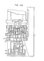
- Figs. 1(A) - 1(D) show an embodiment of the press machine in conformity with the invention for producing a hat shape from a flat sheet steel by performing press operations.
- W is a workpiece.
- the press machine comprises a frame 1, a lower die plate 2 formed with a vertically oriented opening 3 fixedly supported and extending horizontally in an intermediate portion of the frame 1, a lower die 4 of an inverted cup shape fixedly placed on the lower die plate 2, a female cutter 5 secured to the surface of the lower die 4 on the outer side, and a male drawint member 6 secured to the surface of the lower die 4 on the inner side.
- the numeral 11 designates an upper die capable of moving vertically which has a press pressure of 20 - 500 tons applied thereto by an electric motor or hydraulic cylinder means, not shown, through the frame 1.
- the upper die 11 has secured to its undersurface and extending downwardly a male cutter 12 disposed on the outer side, a burring member 13 disposed in the central portion and a punch 14 interposed between the male cutter 12 and the burring member 13.
- the numeral 13A designates a punch attached to a lower end of the burring member 13 for performing preliminary punching for burring.
- Located on the outer periphery of the burring member 13 and between the male drawing member 6 and the upper die 11 is a knockout 15 which is connected to lower ends of cushion pins 16 of cushion means, such as cylinder means, not shown.
- a female drawing member 18 capable of moving vertically which is connected, like the knockout 15, to a lower end of a cushion pin 17 of cushion means, such as cylinder means, not shown.
- the female cutter 5, male drawing member 6, male cutter 12, burring member 13, punches 13A and 14, and a die and a blank holder subsequently to be described can be commonly termed working members.
- the numeral 21 designates cushion means comprising three cylinder means capable of operating independently of one another or a center cushion 23 having a cushion pin 22, an intermediate cushion 25 having a plurality of cushion pins 24 and an outer cushion 27 having a plurality of cushion pins 26.
- the working pressures of the cushions each comprising a hydraulic or pneumatic cylinder can be adjusted in accordance with the requirements of various operations subsequently to be described.
- the cushion pin 22 is connected to a die 28 positioned against the burring member 13 and located within the male drawing member 6.
- the cushion pins 24 are connected respectively to a scrap stripper 29 positioned against the punch 14 and a scrap stripper 30 positioned against the male cutter 12.
- the cushion pins 26 are connected to a blank holder 31 positioned against the female drawing member 18.
- the connections of the cushion pins are as shown in the drawings.
- the vertically oriented opening 3 has a diameter greater than that of the cushion 27 to allow the latter to move therethrough in its upward movement.
- the numeral 32 designates a stripper for guiding scrap following blanking to move same to outside which is automatically shifted horizontally by a steel plate hoop to remove the scrap after one slide stroke is completed. This operation is performed for each cycle of slide stroke for performing operations by the press machine.
- the numeral 33 schematically indicates hydraulic fluid or air supplied from a hydraulic fluid circuit or air circuit providing the cushions with cushion pressures, such as the one shown in Fig. 3.
- the aforesaid cushion operations are performed by a hydraulic fluid circuit shown in Fig. 3 subsequently to be described.
- the downwardly moving blank holder 31 finally abuts against the surface of the lower die 4 and its further downward movement is prevented, thereby completing the drawing operation.
- the female drawing memer 18 Upon the blank holder 31 abutting against the lower die 4, the female drawing memer 18 is also kept from moving downwardly and at the same time the cushion that has applied the drawing load to the female drawing member 18 has its pressure reduced by the same means as described hereinabove.
- the reduction in pressure is effected by detecting the position of the stroke of the press slide or the rotational angle of power means or a press ram.
- preliminary punching is ' effected by the punch 13A of the burring member 13 cooperating with the die 28 as shown in Fig. 3(C) (step 3 in Fig. 2).
- the steps shown in Fig. 1(D) are performed as follows.
- the cushion 23 has its pressure reduced to allow the die 28 to move downwardly. Further downward movement of the press slide allows burring to be effected by the burring member 13.
- the stroke chart shown in Fig. 2 shows the multiple-state press operations performed in a single stroke of the press slide. Multiple-step operations similar to the operations shown in Fig. 2 may be performed by using multiple cushion means capable of adjusting the pressures.
- the invention enables a plurality of steps to be followed in one stroke of the press slide to produce a desired shape from a workpiece. This is made possible according to the invention by providing cushion means comprising cylinder means for selectively driving working members located on the press slide side (upper die side) and the bolster side (lower die side).
- the vertical axis indicates the stroke of the press, having a top dead center U at its upper end and a bottom dead center D at its lower end.
- (.a), (b), (c), (d), (e) and (f) indicate a blanking initiating point, a drawing initiating point, a preliminary punching for burring initiating point, a preliminary punching for burring terminating point, a burring initiating point and a trimming (flange punching and outer periphery trimming) initiating point, respectively, and (g) indicates a trimming terminating point at which all the operations terminate.
- Typical of such cushion means is generally cylinder means relying on hydraulic pressure or air pressure.
- Fig. 3 shows a hydraulic fluid circuit as an example.
- the hydraulic fluid circuit comprises a pump 41 having a cushion cylinder 43 connected to its outlet side through a check valve 42.
- the cushion cylinder 43 has inserted therein a cushion pin 43A for applying cushion pressures to male and female drawing members, dies, a blank holder and other working members required for performing the variety of operations described hereinabove.
- the cushion cylinder 43 hascconnected thereto the following three circuits: the first circuit including a pilot valve 44, a check valve 45 and a relief valve 46; the second circuit including a booster 47; and the third circuit including a solenoid-operated valve 48 connected to the relief valve 46.
- the booster 47 has connected thereto an assembly of a pressure regulator, a water separator and a pressure gauge 50 for hydraulic pressure or air pressure, and pressure gauges 51 and 52.
- the cushion cylinder 43 perform a cushion operation as set by the relief valve 46 upon the solenoid-operated valve 48 being energized.
- the solenoid-operated valve 48 is de-energized to enable the cushion pressure to be kept at a high level by the booster 47.
- the cushion 43 has the high pressure decreased as the pilot valve 44 is actuated, to perform a normal cushion operation (in the case of Fig. 1(B), it has a stripper pressure for punching).
- the press machine is a crank press or the like
- the actuation position of the pilot valve 44 is indicated by a rotary cam direclty connected to the crank shaft.
- the press slide position in motion is indicate both electrically and mechanically.
- press operations including seven operation steps to be followed can be continuously performed in a single stroke of the press slide. This is conductive to a great reduction in cost. Additionally the invention offers the advantages that the expenses for preparing the dies can be reduced and the time for fabricating them can be shortened and the precision of the products can be greatly improved (particularly concentricity and flattenability of inner and outer peripheries can be improved and deflection thereof can be eliminated).
- Figs. 4-7 show examples of application of the invention in which basic technical elements are the same as those shown by referring to the embodiment shown in Figs. 1(A) - 1(D), except that the actuation positions of the cushions and their pressures are different from those of the embodiment shown in Figs. 1(A) - 1(D).
- Fig. 4 shows an example in which an article to be processed through drawing operation in two steps because of the drawing rate can be worked in a single step.
- the numerals 61, 62, 63 and 64 designate a female drawing member, a male side, a male member and cushion pins connected to the male member 63, respectively.
- the numeral 65 designates a blank holder, and the numeral 66 cushion pins connected to the blank holder 65.
- the male member 65 has applied thereto a cushion pressure in such a manner that it is unitary with the male die 62 to enable the workpiece to be shaped as shown in the left half of the figure. Then the cushion pressure applied to the male member 63 is remvoed together with the cushion pressure applied to the blank holder 65, so that the workpiece W can be shaped as shown in the right half of the figure.
- Fig. 5 shows an example of an article shaped by means of the press machine according to the invention in which the flange is required to have a small rounding after being formed by drawing.
- Such article can be shaped in a single operation step. More specifically, as shown in the figure, a female drawing member is split into two members. The female drawing members 71 and 72 are connected to cushion pins 73. The numerals 74 and 75 are a male drawing member and a blank holder respectively, and the numeral 76 designates cushion pins for the blank holder 75.
- preliminary shaping is carried out with the female drawing member 72 being located at a lower level than the female member 71 as shown in a left half of the figure, and then the cushion pressure applied to the female drawing member 72 is released before the female drawing member 71 is mvoed downwardly, so as to form the workpiece into the desired shape.
- Fig. 6 shows an example in which the workpiece is formed into a cylindrical shape by flanging after the outer periphery disturbed by the shifting of the material by drawing is trimmed.
- the numerals 81, 82, 83, 84, 85, 86, 87 and 88 designate a female drawing member, a female drawing member, cushion pins for the female drawing member 82, a male drawing member, a blank holder, cushion pins for the blank holder 85, a blank holder and cushion pins for the blank holder 87, respectively.
- the workpiece is operated on first by moving downwardly the female drawing members 81 and 82 arranged unitarily and the blank holders 85 and 87 also arranged unitarily and positioned against the female drawing members 81 and 82 to form the workpiece into a hat shape with a flange by drawing as shown in a left half of the figure, and then by allowing the blank holder 85 to perform a cushion operation and escape downwardly after the blank holder 87 abuts against the lower die 4 to thereby form a cylindrical shape as shown in a right half of the figure.
- Fig. 7 shows an example in which a plurality of bending operations are performed.
- an upwardly bending die 91 is connected to a cushion pin 92, and a stripper 93 is connected to cushion pins 94.
- An upwardly bending member 95 is secured to the upper die 11 ; and another stripper 96 is connected to a cushion pin 97.
- the lower die 4 has a downwardly bending die 98 fixedly placed thereon.
- Still another stripper 99 is connected to cushion pins 100. In operation, the stripper 99 escapes downwardly as shown in a right half of the figure as soon as the stripper 96 abuts against the lower-.die 4, to thereby finishing bending of the peripheral portion of the workpiece.
- the present invention can achieve the excellent effects of completing a series of press operations in a single stroke of the press slide.
- This feature has been made possible by virtue of the provision of the cushion means which enbales cushion pressures to be applied to dies, punches, burring member, drawing members, strippers, trimming members and other press working members.
- the cushion means comprises a pluraliry of cushions that can have their actuation positions and the pressures applied thereby controlled as desired.
Abstract
A press machine including an upper die (11), a lower die (4) and a plurality of working members (5, 6, 12, 13, 13A, 14, 31) associated with the upper die and the lower die for performing predetermined press operations. The working members are capable of relative movement separately from and independently of other working members. The press machine further includes cushion means (21) applying a predetermined working pressure to a predetermined one of the working members. The cushion means has cushion pressures adjustable as the operation steps are followed in performing press operations, whereby a plurality of dissimilar press operations can be performed in chronological sequence in a single stroke of a press slide. The press machine is compact in size, high in versatility and low in cost.
Description
- This invention relates to press machines suitable for performing operations on a flat sheet steel to form same into a desired shape by performing cutting, punching, bending, drawing and other operations, and more particularly it is concerned with a press machine of the type capable of performing, in a single stroke of the press slide, a plurality of operations including a plurality of similar operations or dissimilar operations.
- When a blank in flat sheet steel form is worked to produce parts of a hat shape formed with a mounting opening in the flange, it is necessary that cutting, drawing and punching process steps be followed one after another. Drawing inevitably causes shifting (including expansion and contraction) of the material, so that punching need be performed after drawing is performed.
- Heretofore, it has been usual practice to perform punching after drawing is carried out and to use separate presses to perform these two operations. Thus it has been necessary in the past to use a plurality of presses for performing operations including a plurality of process steps to be followed. Therefore, to this end, it has been necessary for operation administrators to ensure that a space large enough to install a plurality of presses and necessary attachments therein is set aside for this purpose and at the same time to pay attention to providing means for tarnsferring workpieces between the plurality of presses. The transfer means generally comprises automatic transfer machines which rely on robots. However, in the event that it is impossible to use robots for some reason, transfer of the workpieces should be carried out manually. No matter what transfer means may be used, the time spent in transferring the workpieces is essentially wasted in terms of press operations and gives rise to the problem that the total operation time is prolonged. To obviate this problem, a proposal has been made to use what is generally referred to as a transfer press comprising a single press of a large size for simultaneously and synchronously performing a plurality of operations, and means for transferring workpieces to the next following station in synchronism with the oprations performed on the workpieces by the press. The transfer press offers an advantage in that the operation time can be gre.atly_wshortened because the workpiece transfer time can:-be greatly decreased. However, some disadvantages are associated with this proposal. The press should be capable of performing operations that require a total of press capacities necessary for performing a variety of operations and such press is inevitably very expensive. Since such press should be a special machine, difficulties are faced with in readily replacing the dies with different types of die to meet the requirements of altering the shape to be produced by press working.
- The two types of press referred'to hereinabove have disadvantages which appear to be attributed to the arrangement whereby workpieces are moved in a direction at right angles (generally horizontally) to the press slide.
- In view of the foregoing, the present invention contemplates performing the aforesaid plurality of operations in a single stroke of the press slide.
- A principal object of the invention is to provide a press machine capable of performing a plurality of operations one after another in a single stroke of the press slide, to thereby greatly decrease the working time necessary for performing the operations.
- Another object is to provide a press machine of high versatility and low press pressure capable of satisfying the needs of performing a variety of types of operation.
- Still another object is to provide a structural arrangement and control means having effect in enabling the aforesaid objects to be accomplished.
- The outstanding characteristic of the invention enabling the aforesaid objects to be accomplished is that a plurality of dies each intended to perform a specific operation are combined to form an assembly, and such assembly of dies is made to operate in such a manner that at the time an initial operation has been completed in one slide stroke, the die used in the initial operation and now becoming useless has its pressure instantaneously reduced and the operation of the next process step is performed in the same slide stroke by using the die of the next process step in series or in parallel, whereby a plurality of operations can be performed by the single press in a single press slide stroke without requiring to increase the press capacity (press pressure).
-
- Figs. 1(A) - 1(D) show the press machine according to the invention engaged in the production of a part of a hat shape by performing a plurality of operations on a sheet steel, Fig. 1(A) showing the press machine performing blanking, Fig. 1(B) showing same performing drawing, Fig. 1(C) showing same performing preliminary punching for burring, and Fig. 1(D) showing same as it has completed burring, flange punching and outer periphery trimming;
- Fig. 2 is a diagram showing the timing of various operations shown in relation to the stroke of the press and the process steps;
- Fig. 3 is a circuit diagram for providing cushion pressures;
- Fig. 4 shows an example of application of the invention in redrawing;
- Fig. 5 shows an example of application of the invention in rounding the flange;
- Fig. 6 shows an example of application-of the invention in performing trimming followed by flaring; and
- Fig. 7 shows an example of application of the invention in performing bending twice.
- A preferred embodiment of the invention suitable for accomplishing the aforesaid objects will now be described by referring to the accompanying drawings.
- Figs. 1(A) - 1(D) show an embodiment of the press machine in conformity with the invention for producing a hat shape from a flat sheet steel by performing press operations. In the drawings, W is a workpiece. The press machine comprises a frame 1, a
lower die plate 2 formed with a vertically orientedopening 3 fixedly supported and extending horizontally in an intermediate portion of the frame 1, alower die 4 of an inverted cup shape fixedly placed on thelower die plate 2, afemale cutter 5 secured to the surface of thelower die 4 on the outer side, and amale drawint member 6 secured to the surface of thelower die 4 on the inner side. - The numeral 11 designates an upper die capable of moving vertically which has a press pressure of 20 - 500 tons applied thereto by an electric motor or hydraulic cylinder means, not shown, through the frame 1. The upper die 11 has secured to its undersurface and extending downwardly a
male cutter 12 disposed on the outer side, aburring member 13 disposed in the central portion and apunch 14 interposed between themale cutter 12 and theburring member 13. Thenumeral 13A designates a punch attached to a lower end of theburring member 13 for performing preliminary punching for burring. Located on the outer periphery of theburring member 13 and between themale drawing member 6 and the upper die 11 is a knockout 15 which is connected to lower ends ofcushion pins 16 of cushion means, such as cylinder means, not shown. Interposed between the knockout 15 and themale cutter 12 is afemale drawing member 18 capable of moving vertically which is connected, like the knockout 15, to a lower end of acushion pin 17 of cushion means, such as cylinder means, not shown. Thefemale cutter 5,male drawing member 6,male cutter 12,burring member 13,punches - The
numeral 21 designates cushion means comprising three cylinder means capable of operating independently of one another or acenter cushion 23 having acushion pin 22, anintermediate cushion 25 having a plurality ofcushion pins 24 and anouter cushion 27 having a plurality ofcushion pins 26. The working pressures of the cushions each comprising a hydraulic or pneumatic cylinder can be adjusted in accordance with the requirements of various operations subsequently to be described. Thecushion pin 22 is connected to a die 28 positioned against theburring member 13 and located within themale drawing member 6. Thecushion pins 24 are connected respectively to ascrap stripper 29 positioned against thepunch 14 and ascrap stripper 30 positioned against themale cutter 12. Thecushion pins 26 are connected to ablank holder 31 positioned against thefemale drawing member 18. The connections of the cushion pins are as shown in the drawings. The vertically orientedopening 3 has a diameter greater than that of thecushion 27 to allow the latter to move therethrough in its upward movement. Thenumeral 32 designates a stripper for guiding scrap following blanking to move same to outside which is automatically shifted horizontally by a steel plate hoop to remove the scrap after one slide stroke is completed. This operation is performed for each cycle of slide stroke for performing operations by the press machine. Thenumeral 33 schematically indicates hydraulic fluid or air supplied from a hydraulic fluid circuit or air circuit providing the cushions with cushion pressures, such as the one shown in Fig. 3. - In the aforesaid construction, downward movement of a press slide produces the workpiece W by blanking from a flat sheet steel (step 1, Fig. 2) as shown in Fig. 1(A) by means of the
female cutter 5 cooperating with themale cutter 12. At this time, the knockout 15 andfemale drawing member 18 on the upper die 11 side and the die 28,scrap strippers blank holder 31 on thelower die 4 side have predetermined pressures applied thereto by the respective cushions while being disposed in the illustrated positions, to be ready for the next following operation step. - Further downward movement of the press slide causes the
female drawing member 18,male drawing member 6 andblank holder 31 to perform drawing as shown in Fig. 1(B). At this time, thefemale drawing member 18 is connected to thecushion pin 17 associated with a cushion of a pressure higher than the drwing load applied, and theblank holder 31 performs a normal cushion operation. Stated differently, theblank holder 31 is urged to mvoe upwardly by thecushion 27 with a force that suits the drawing operation, so that theblank holder 31 can absorb the shock while being maintained at the upwardly biasing pressure set by thecushion 27 although it tends to be moved downwardly by thefemale drawing member 18 urged downwardly with a force higher than the drawing load. The aforesaid cushion operations are performed by a hydraulic fluid circuit shown in Fig. 3 subsequently to be described. The downwardly movingblank holder 31 finally abuts against the surface of thelower die 4 and its further downward movement is prevented, thereby completing the drawing operation. - Upon the
blank holder 31 abutting against thelower die 4, thefemale drawing memer 18 is also kept from moving downwardly and at the same time the cushion that has applied the drawing load to thefemale drawing member 18 has its pressure reduced by the same means as described hereinabove. The reduction in pressure is effected by detecting the position of the stroke of the press slide or the rotational angle of power means or a press ram. - As the press slide further moves downwardly, preliminary punching is' effected by the
punch 13A of theburring member 13 cooperating with thedie 28 as shown in Fig. 3(C) (step 3 in Fig. 2). The steps shown in Fig. 1(D) (steps cushion 23 has its pressure reduced to allow the die 28 to move downwardly. Further downward movement of the press slide allows burring to be effected by the burringmember 13. - As the burring operation nears completion, punching of the flange and trimming of the outer periphery are performed by the
punch 14 andmale cutter 12 attached to the upper side 11 cooperating with theblank holder 31. At this point in time, all the press operations are completed, so that the press slide is disposed in the bottom dead center. - The stroke chart shown in Fig. 2 shows the multiple-state press operations performed in a single stroke of the press slide. Multiple-step operations similar to the operations shown in Fig. 2 may be performed by using multiple cushion means capable of adjusting the pressures. Thus the invention enables a plurality of steps to be followed in one stroke of the press slide to produce a desired shape from a workpiece. This is made possible according to the invention by providing cushion means comprising cylinder means for selectively driving working members located on the press slide side (upper die side) and the bolster side (lower die side).
- In Fig. 2, the vertical axis indicates the stroke of the press, having a top dead center U at its upper end and a bottom dead center D at its lower end. In the diagram shown in Fig. 2, (.a), (b), (c), (d), (e) and (f) indicate a blanking initiating point, a drawing initiating point, a preliminary punching for burring initiating point, a preliminary punching for burring terminating point, a burring initiating point and a trimming (flange punching and outer periphery trimming) initiating point, respectively, and (g) indicates a trimming terminating point at which all the operations terminate.
- To perform the aforesaid operations continuously in a smooth fashion, it is necessary that specific cushion means for enabling a predetermined operation of all the opeations to be performed by provided. Typical of such cushion means is generally cylinder means relying on hydraulic pressure or air pressure. Fig. 3 shows a hydraulic fluid circuit as an example. The hydraulic fluid circuit comprises a
pump 41 having acushion cylinder 43 connected to its outlet side through acheck valve 42. Thecushion cylinder 43 has inserted therein acushion pin 43A for applying cushion pressures to male and female drawing members, dies, a blank holder and other working members required for performing the variety of operations described hereinabove. Thecushion cylinder 43 hascconnected thereto the following three circuits: the first circuit including apilot valve 44, acheck valve 45 and arelief valve 46; the second circuit including abooster 47; and the third circuit including a solenoid-operatedvalve 48 connected to therelief valve 46. Thebooster 47 has connected thereto an assembly of a pressure regulator, a water separator and apressure gauge 50 for hydraulic pressure or air pressure, andpressure gauges - In the hydraulic fluid circuit shown in Fig. 3, the
cushion cylinder 43 perform a cushion operation as set by therelief valve 46 upon the solenoid-operatedvalve 48 being energized. When thecushion pin 43A is made to function as a draw pin for effecting drawing as shown in Fig. 1(B), the solenoid-operatedvalve 48 is de-energized to enable the cushion pressure to be kept at a high level by thebooster 47. Depending on the position in which setting is carried out, thecushion 43 has the high pressure decreased as thepilot valve 44 is actuated, to perform a normal cushion operation (in the case of Fig. 1(B), it has a stripper pressure for punching). - When the press machine is a crank press or the like, the actuation position of the
pilot valve 44 is indicated by a rotary cam direclty connected to the crank shaft. However, in a power press, the press slide position in motion is indicate both electrically and mechanically. - In the embodiment of the invention shown and described hereinabove, press operations including seven operation steps to be followed can be continuously performed in a single stroke of the press slide. This is conductive to a great reduction in cost. Additionally the invention offers the advantages that the expenses for preparing the dies can be reduced and the time for fabricating them can be shortened and the precision of the products can be greatly improved (particularly concentricity and flattenability of inner and outer peripheries can be improved and deflection thereof can be eliminated).
- Figs. 4-7 show examples of application of the invention in which basic technical elements are the same as those shown by referring to the embodiment shown in Figs. 1(A) - 1(D), except that the actuation positions of the cushions and their pressures are different from those of the embodiment shown in Figs. 1(A) - 1(D).
- Fig. 4 shows an example in which an article to be processed through drawing operation in two steps because of the drawing rate can be worked in a single step. In the figure, the
numerals male member 63, respectively. The numeral 65 designates a blank holder, and the numeral 66 cushion pins connected to theblank holder 65. - Initially the
male member 65 has applied thereto a cushion pressure in such a manner that it is unitary with the male die 62 to enable the workpiece to be shaped as shown in the left half of the figure. Then the cushion pressure applied to themale member 63 is remvoed together with the cushion pressure applied to theblank holder 65, so that the workpiece W can be shaped as shown in the right half of the figure. - Fig. 5 shows an example of an article shaped by means of the press machine according to the invention in which the flange is required to have a small rounding after being formed by drawing. Such article can be shaped in a single operation step. More specifically, as shown in the figure, a female drawing member is split into two members. The
female drawing members numerals 74 and 75 are a male drawing member and a blank holder respectively, and the numeral 76 designates cushion pins for the blank holder 75. In operation, preliminary shaping is carried out with thefemale drawing member 72 being located at a lower level than thefemale member 71 as shown in a left half of the figure, and then the cushion pressure applied to thefemale drawing member 72 is released before thefemale drawing member 71 is mvoed downwardly, so as to form the workpiece into the desired shape. - Fig. 6 shows an example in which the workpiece is formed into a cylindrical shape by flanging after the outer periphery disturbed by the shifting of the material by drawing is trimmed. In the figure, the
numerals blank holder 85, a blank holder and cushion pins for theblank holder 87, respectively. The workpiece is operated on first by moving downwardly thefemale drawing members 81 and 82 arranged unitarily and theblank holders female drawing members 81 and 82 to form the workpiece into a hat shape with a flange by drawing as shown in a left half of the figure, and then by allowing theblank holder 85 to perform a cushion operation and escape downwardly after theblank holder 87 abuts against thelower die 4 to thereby form a cylindrical shape as shown in a right half of the figure. - Fig. 7 shows an example in which a plurality of bending operations are performed. In the figure, an upwardly bending
die 91 is connected to acushion pin 92, and a stripper 93 is connected to cushion pins 94. An upwardly bendingmember 95 is secured to the upper die 11; and anotherstripper 96 is connected to acushion pin 97. Thelower die 4 has a downwardly bending die 98 fixedly placed thereon. Still anotherstripper 99 is connected to cushion pins 100. In operation, thestripper 99 escapes downwardly as shown in a right half of the figure as soon as thestripper 96 abuts against the lower-.die 4, to thereby finishing bending of the peripheral portion of the workpiece. - From the foregoing description, it will be appreciated that the present invention can achieve the excellent effects of completing a series of press operations in a single stroke of the press slide. This feature has been made possible by virtue of the provision of the cushion means which enbales cushion pressures to be applied to dies, punches, burring member, drawing members, strippers, trimming members and other press working members. The cushion means comprises a pluraliry of cushions that can have their actuation positions and the pressures applied thereby controlled as desired. By combinihg.ithe cushion means organically with a press, it is possible to obtain a press machine of high versatility that can perform a plurality of operation steps in a single stroke of the press slide. It is to be understood that the invention is not limited to the specific form of the enbodiment and the examples of application shown and described hereinabove, and that many changes and modifications may be made to the applications within the scope of the invention. The results achieved by the invention are summarized as follows:
- (1) Articles produced by means of a press can have their cost greatly reduced because a plurality of operation steps can be performed in a single stroke of the press slide.
- (2) The expenses for preparing the dies can be greatly reduced because the die can be adapted to use for different purposes to perform a plurality of operation steps in a single stroke of the press slide. Thus many parts can be shared by different operation steps.
- (3) The need to use a plurality of preses for performing a plurality of operation steps is eliminated, thereby allowing a great reduction to be achieved in the operation space.
- (4) Since the shaping of an article is performed in a multiplicity of stages in a single stroke of the press side, the precision with which the shaping is effected can be greatly improved. Particularly excellent results can be obtained in achieving concentricity and eliminating deflection of the inner and outer peripheries.
- (5) The press load can be greatly reduced as compared with that of a transfer press in which a plurality of operation steps are simultaneously performed, because the press capacity is determined by the operation step requiring the highest load to be applied since the operations requiring a plurality of steps to be followed are performed in chronological sequence.
- Thus the invention makes a valuable contribution to the progress of indstrial production.
Claims (8)
1. A press machine comprising:
a frame (1); and
an upper die (11) and a lower (4) supported by said frame for repeated relative movement towrad and away from each other, said upper die and lower die having a workpiece comprising a sheet steel material positioned therebetween for performing press operations thereon by the interaction of the upper die and the lower die to form the workpiece into a predetermined shape; wherein the improvement comprises:
a plurality of working members (5, 6, 12, 13, 13A, 14, 31) associated with said upper die and lower die for performing predetermined press operations on the workpiece, said working members being able to move relative to one another separately from and independently of other working members; and
cushion means (21) applying a predetermined working pressure to a predetermined working member of said working members, said cushion means having cushion pressures being adjusted in accordance with the progress of the press operations through different operation steps.
2. A press machine as claimed in claim 1, wherein adjustments of the cushion pressures of said cushion means are effected in conformity with the stroke of a press slide.
3. A press machine as claimed in claim 2, wherein said cushion means have the cushion pressures reduced in conformity with the stroke of the press slide.
4. A press machine as claimed in claim 1, wherein said cushion means comprises cylinder means.
5. A press machine as claimed in claim 1, wherein the cushion pressure for applying a predetermined pressure to a predetermined working member split into a plurality of members is successively adjusted in accordance with , the operation steps, whereby a plurality of press operations can be performed in chronological sequence in a single stroke of a press slide.
6. A press machine as claimed in claim 5, wherein press operations distinct from one another at least in kind are performed in chronological sequence.
7. A press machine as claimed in claim 4, wherein said cylinder means is connected to a circuit including a pump, a pilot valve, a solenoid-operated valve, a relief valve and a booster.
8. A press machine as claimed in claim 7, wherein said cushion means has a predetermined pressure applied thereto through the relief valve and has the pressures reduced through the pilot valve actuated in response to rotation of a crank shaft.
Applications Claiming Priority (2)
| Application Number | Priority Date | Filing Date | Title |
|---|---|---|---|
| JP29267/81 | 1981-02-28 | ||
| JP56029267A JPS57142726A (en) | 1981-02-28 | 1981-02-28 | One stroke multiple stage forming press |
Publications (2)
| Publication Number | Publication Date |
|---|---|
| EP0059432A2 true EP0059432A2 (en) | 1982-09-08 |
| EP0059432A3 EP0059432A3 (en) | 1983-05-18 |
Family
ID=12271497
Family Applications (1)
| Application Number | Title | Priority Date | Filing Date |
|---|---|---|---|
| EP82101441A Withdrawn EP0059432A3 (en) | 1981-02-28 | 1982-02-25 | Press machine |
Country Status (2)
| Country | Link |
|---|---|
| EP (1) | EP0059432A3 (en) |
| JP (1) | JPS57142726A (en) |
Cited By (9)
| Publication number | Priority date | Publication date | Assignee | Title |
|---|---|---|---|---|
| EP0252635A2 (en) * | 1986-07-03 | 1988-01-13 | Hideo Hoshi | Complex pressing die apparatus |
| US4918956A (en) * | 1987-08-27 | 1990-04-24 | The Minster Machine Company | Monitorable and compensatable feedback tool and control system for a press using a solid tool backup element |
| US4939918A (en) * | 1987-08-27 | 1990-07-10 | The Minster Machine Company | Monitorable and compensatable feedback tool and control system for a press |
| US4945742A (en) * | 1987-08-27 | 1990-08-07 | The Minster Machine Company | Monitorable and compensatable feedback tool and control system for a press |
| US5007817A (en) * | 1990-01-19 | 1991-04-16 | Wallis Bernard J | Press with die cushion gas monitor |
| CN102397947A (en) * | 2011-10-26 | 2012-04-04 | 铜陵百瑞豪科技有限公司 | Composite die for edge cutting and punching |
| EP2117743B1 (en) | 2007-03-01 | 2015-08-05 | Schuler Pressen GmbH | Cooling device for a plate |
| CN105689530A (en) * | 2016-02-17 | 2016-06-22 | 深圳市金力丰五金制造有限公司 | Riveting equipment |
| CN108262388A (en) * | 2017-12-07 | 2018-07-10 | 佛山市南海兴迪机械制造有限公司 | A kind of continuous drawing formula hydraulic drawing press |
Families Citing this family (17)
| Publication number | Priority date | Publication date | Assignee | Title |
|---|---|---|---|---|
| JPS6261324U (en) * | 1985-10-02 | 1987-04-16 | ||
| JPS6356918U (en) * | 1986-09-29 | 1988-04-16 | ||
| JPH0620568B2 (en) * | 1987-08-31 | 1994-03-23 | アイダエンジニアリング株式会社 | Press processing method for bossed products |
| JP2787947B2 (en) * | 1988-09-27 | 1998-08-20 | 曙ブレーキ工業株式会社 | Toggle press equipment |
| KR100436006B1 (en) * | 2001-04-02 | 2004-06-23 | 주식회사 드림텍 | Tool equipment form possible press one stroke |
| KR20020094548A (en) * | 2001-06-12 | 2002-12-18 | 현대자동차주식회사 | Compound press system |
| KR100412656B1 (en) * | 2001-06-15 | 2003-12-31 | 현대자동차주식회사 | Press system |
| KR100412684B1 (en) * | 2001-09-17 | 2003-12-31 | 현대자동차주식회사 | Press die capable of trimming and flanging at a time |
| KR100474811B1 (en) * | 2001-12-20 | 2005-03-08 | 주식회사 현동 | Forging Apparatus for Metallic Pan |
| CN100402177C (en) * | 2006-07-19 | 2008-07-16 | 中国重型汽车集团有限公司 | Punch process of integral automobile metal bumper |
| CN102397946A (en) * | 2011-10-26 | 2012-04-04 | 铜陵百瑞豪科技有限公司 | Blanking and drawing die |
| CN102397945A (en) * | 2011-10-26 | 2012-04-04 | 铜陵百瑞豪科技有限公司 | Trimming and punching die |
| JP5796710B2 (en) * | 2011-12-12 | 2015-10-21 | トヨタ自動車株式会社 | Press machine |
| CN103317029A (en) * | 2013-07-05 | 2013-09-25 | 蚌埠金威滤清器有限公司 | Punching composite die for filter element end cover |
| CN105363897A (en) * | 2015-02-14 | 2016-03-02 | 湖南同心模具制造有限公司 | Automobile part production method |
| CN105057431A (en) * | 2015-08-11 | 2015-11-18 | 苏州市越海拉伸机械有限公司 | Multi-station hydraulic drawing machine |
| CN105057429A (en) * | 2015-08-11 | 2015-11-18 | 苏州市越海拉伸机械有限公司 | Multi-station drawing mechanism of hydraulic drawing machine |
Citations (4)
| Publication number | Priority date | Publication date | Assignee | Title |
|---|---|---|---|---|
| FR525873A (en) * | 1918-04-04 | 1921-09-28 | Louis Ferdinand Gros | Cutting and stamping machine |
| GB256865A (en) * | 1926-02-09 | 1926-08-19 | Marquette Tool And Mfg Company | Improvements in and relating to blank-holders for presses for drawing sheet metal |
| US2318819A (en) * | 1940-12-12 | 1943-05-11 | David C Verson | Multiple action punch press die and cushion |
| US3786667A (en) * | 1971-10-26 | 1974-01-22 | Reynolds Metals Co | Apparatus for and method of making a nestable container |
-
1981
- 1981-02-28 JP JP56029267A patent/JPS57142726A/en active Pending
-
1982
- 1982-02-25 EP EP82101441A patent/EP0059432A3/en not_active Withdrawn
Patent Citations (4)
| Publication number | Priority date | Publication date | Assignee | Title |
|---|---|---|---|---|
| FR525873A (en) * | 1918-04-04 | 1921-09-28 | Louis Ferdinand Gros | Cutting and stamping machine |
| GB256865A (en) * | 1926-02-09 | 1926-08-19 | Marquette Tool And Mfg Company | Improvements in and relating to blank-holders for presses for drawing sheet metal |
| US2318819A (en) * | 1940-12-12 | 1943-05-11 | David C Verson | Multiple action punch press die and cushion |
| US3786667A (en) * | 1971-10-26 | 1974-01-22 | Reynolds Metals Co | Apparatus for and method of making a nestable container |
Cited By (10)
| Publication number | Priority date | Publication date | Assignee | Title |
|---|---|---|---|---|
| EP0252635A2 (en) * | 1986-07-03 | 1988-01-13 | Hideo Hoshi | Complex pressing die apparatus |
| EP0252635A3 (en) * | 1986-07-03 | 1990-01-17 | Hideo Hoshi | Complex pressing die apparatus |
| US4918956A (en) * | 1987-08-27 | 1990-04-24 | The Minster Machine Company | Monitorable and compensatable feedback tool and control system for a press using a solid tool backup element |
| US4939918A (en) * | 1987-08-27 | 1990-07-10 | The Minster Machine Company | Monitorable and compensatable feedback tool and control system for a press |
| US4945742A (en) * | 1987-08-27 | 1990-08-07 | The Minster Machine Company | Monitorable and compensatable feedback tool and control system for a press |
| US5007817A (en) * | 1990-01-19 | 1991-04-16 | Wallis Bernard J | Press with die cushion gas monitor |
| EP2117743B1 (en) | 2007-03-01 | 2015-08-05 | Schuler Pressen GmbH | Cooling device for a plate |
| CN102397947A (en) * | 2011-10-26 | 2012-04-04 | 铜陵百瑞豪科技有限公司 | Composite die for edge cutting and punching |
| CN105689530A (en) * | 2016-02-17 | 2016-06-22 | 深圳市金力丰五金制造有限公司 | Riveting equipment |
| CN108262388A (en) * | 2017-12-07 | 2018-07-10 | 佛山市南海兴迪机械制造有限公司 | A kind of continuous drawing formula hydraulic drawing press |
Also Published As
| Publication number | Publication date |
|---|---|
| JPS57142726A (en) | 1982-09-03 |
| EP0059432A3 (en) | 1983-05-18 |
Similar Documents
| Publication | Publication Date | Title |
|---|---|---|
| EP0059432A2 (en) | Press machine | |
| US4905556A (en) | Blanking press | |
| US7287408B2 (en) | Apparatus and method of producing battery case | |
| US6530255B1 (en) | Forming press apparatus | |
| US5526668A (en) | Index-feed machining system | |
| JPH02104431A (en) | Method and device for molding, remolding and edge-rolling in shell in one press | |
| CN110153288A (en) | A kind of mold of metal plate U-shaped part bending and forming | |
| US4996864A (en) | Drawing machine | |
| JP2551961B2 (en) | Press machine with welding gun | |
| EP0137580B1 (en) | Method and apparatus for drawing heavy wall shells with a multi-step inside edge | |
| EP0101146A1 (en) | Method and apparatus for drawing heavy wall shells | |
| CN217798429U (en) | Blanking, drawing and punching composite die and equipment using same | |
| CN111014446A (en) | Full-automatic production device for stamping and stretching | |
| CN105880376A (en) | Bending blanking mold | |
| JP3531441B2 (en) | Composite press mold | |
| CN212329391U (en) | Material pressing device for secondary stretching of material | |
| US4183238A (en) | Double acting precision deep-stamping press | |
| US11779988B2 (en) | Fine blanking system and method of operating | |
| EP0549955B1 (en) | Method of the fluidised bed type for the shaping of sheet metal | |
| JPS6182944A (en) | Production of shaft component with large-sized flange | |
| CN111421042A (en) | Bidirectional drawing forming method | |
| US4559802A (en) | Method for drawing heavy wall shells | |
| US3654795A (en) | Process for producing cup-shaped objects having axially extending lips | |
| US11833565B2 (en) | Device for forming a sheet-metal workpiece | |
| CN1075749C (en) | Cold-forging forming method for cover of gas generator of car safety air-bag |
Legal Events
| Date | Code | Title | Description |
|---|---|---|---|
| PUAI | Public reference made under article 153(3) epc to a published international application that has entered the european phase |
Free format text: ORIGINAL CODE: 0009012 |
|
| AK | Designated contracting states |
Designated state(s): DE GB |
|
| PUAL | Search report despatched |
Free format text: ORIGINAL CODE: 0009013 |
|
| AK | Designated contracting states |
Designated state(s): DE GB |
|
| 17P | Request for examination filed |
Effective date: 19830519 |
|
| STAA | Information on the status of an ep patent application or granted ep patent |
Free format text: STATUS: THE APPLICATION HAS BEEN WITHDRAWN |
|
| 18W | Application withdrawn |
Withdrawal date: 19840709 |
|
| RIN1 | Information on inventor provided before grant (corrected) |
Inventor name: HIROSE, FUMIO |