EP0056686A2 - Access control card - Google Patents
Access control card Download PDFInfo
- Publication number
- EP0056686A2 EP0056686A2 EP82300063A EP82300063A EP0056686A2 EP 0056686 A2 EP0056686 A2 EP 0056686A2 EP 82300063 A EP82300063 A EP 82300063A EP 82300063 A EP82300063 A EP 82300063A EP 0056686 A2 EP0056686 A2 EP 0056686A2
- Authority
- EP
- European Patent Office
- Prior art keywords
- signal
- clock
- card
- received signal
- stored code
- Prior art date
- Legal status (The legal status is an assumption and is not a legal conclusion. Google has not performed a legal analysis and makes no representation as to the accuracy of the status listed.)
- Ceased
Links
Images


Classifications
-
- G—PHYSICS
- G07—CHECKING-DEVICES
- G07C—TIME OR ATTENDANCE REGISTERS; REGISTERING OR INDICATING THE WORKING OF MACHINES; GENERATING RANDOM NUMBERS; VOTING OR LOTTERY APPARATUS; ARRANGEMENTS, SYSTEMS OR APPARATUS FOR CHECKING NOT PROVIDED FOR ELSEWHERE
- G07C9/00—Individual registration on entry or exit
- G07C9/20—Individual registration on entry or exit involving the use of a pass
- G07C9/29—Individual registration on entry or exit involving the use of a pass the pass containing active electronic elements, e.g. smartcards
-
- G—PHYSICS
- G07—CHECKING-DEVICES
- G07C—TIME OR ATTENDANCE REGISTERS; REGISTERING OR INDICATING THE WORKING OF MACHINES; GENERATING RANDOM NUMBERS; VOTING OR LOTTERY APPARATUS; ARRANGEMENTS, SYSTEMS OR APPARATUS FOR CHECKING NOT PROVIDED FOR ELSEWHERE
- G07C9/00—Individual registration on entry or exit
- G07C9/20—Individual registration on entry or exit involving the use of a pass
- G07C9/28—Individual registration on entry or exit involving the use of a pass the pass enabling tracking or indicating presence
Definitions
- the present invention relates to an access control card useful in access control systemsto permit access to secured areas, secured information, secured systems or the like.
- Access control systems have been utilized in the past to restrict access to protected areas, information, or the like to only those to whom access is authorized. Such systems usually involve a card reader into which a coded card is inserted and read. The code on the card, which may periodically be changed, may be identical for all those wishing to have access. Alternatively, each person who is authorized to have access may be assigned his own personal code which again may be periodically changed. Upon the recognition of a permissible code, the card reader and associated system will permit access.
- These card readers usually comprise a cabinet for housing the access control system or subsystem thereof and typically have a plurality of sensing fingers for making contact with the cards inserted into the reader and for sensing the code on the card to allow access if the card carrier has the proper code. To gain access, the card is inserted into a slot in the cabinet which resulsts in the wiping over of the surface of the card by the sensing fingers during both this insertion and the subsequent withdrawl of the card.
- Patent 4,210,900 shows a surface acoustic wave device for receiving an RF generated signal and for transmitting a coded RF signal in response thereto to a card reader.
- Patent 4,210,900 shows one way around this problem by providing a card which can be inserted into a reader but which does not require physical contact with any part of the reader and in which the sensing elements of the reader can be sealed from exposure.
- an access control card for use in an access control system, characterized in that the card comprises a battery, a wireless signal receiver, including an antenna, receiving a coded wireless signal generated by a card reader; a clock connected to the battery and the receiver supplying a rec- . eived signal based upon said coded wireless signal; a memory storing first and second stored codes; and comparator and transmit means comparing said first stored code and said received signal and for transmitting said second stored code when there is a match between said received signal and said first stored code.
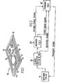
- the access control card 10 has a subbase 12 made of a suitable plastics or similar material.
- the card can receive any type of wireless transmission from a transmitter such as ultrasonic, infrared, etc.; the preferred embodiment according to the present system uses RF transmissions.
- antenna 11 (which may be any other type of wireless signal sensing means depending upon the form of energy used in the transmission) is wound in loop form around the periphery of subbase 12 and is connected to a printed circuit type board 13 located centrally of subbase 12.
- the printed circuit board 13 supports a battery 14 which forms the power source for access control card 10 and may be a lithium battery for small size and long life.
- circuit elements 15 to 18 comprising capacitors and resistors of the card mounted system
- chip 19 comprising the logic gates, latches, flip-flops and counters
- FIG. 2 The block diagram of the circuit mounted on subbase 12 is shown in Figure 2. Each block contains the name of the function for the block and the corresponding figure number of the figure showing the details of the block.
- the system mounted on subbase 12 comprises the antenna 11 which is used for receiving the radio frequency generated signal from a card reader and to transmit the access control card code (second stored code) back to the reader for varification.
- antenna 11 may comprise an antenna for receiving the signal transmitted by the card reader and a separate antenna for transmitting the card code back to the card reader, in the preferred embodiment it comprises the single loop 11 wound around the periphery of the card.
- the signal received by antenna 11 is transmitted to a clock/receiver circuit 20.
- the receive circuit initializes the operation of a clock which then controls the overall functioning of the system mounted on subbase 12. Specifically, the clock in clock/receiver 20 clocks memory 50 to supply a first coded signal to transmit circuit 80.
- the receiver portion of clock/receiver 20 supplies the received signal or a received signal based upon the radio frequency signal received by antenna 11 to transmit circuit 80. Transmit circuit 80 compares the first coded signal with the received signal.
- the clock continued to drive memory 50 to then supply the second coded signal to transmit circuit 80 which then supplies this second coded signal as a transmit signal, via circuit 80, to antenna 11 for transmission back to the card reader.
- the second coded signal is not supplied by transmit circuit 80 as a transmit signal to the antenna 11.
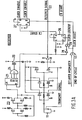
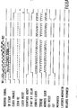
- the coded radio frequency signal which is connected through as a received signal, comprises a continuous carrier signal 101 terminated by a start bit 102 and a series of 16 data bits 103.
- the clock shown in Figure 3B synchronizes to the trailing edge of the carrier, skips the start bit space and then begins addressing memory 50 shown in Figure 4.
- Antenna 11 is shown in Figure 3A which also shows the receiver portion of clock/receiver 20. Antenna 11 receives the RF transmission from the card reader and supplies this signal through amplifiers 5 and 6 to switch 7 which acts as a charge and discharge control for capacitor 8. The charge across the capacitor is then connected through inverter 9 and provides the received signal shown in Figure 6A.
- a switch 25 is provided between the battery and the amplifier sections 5 and 6 to the receiver.
- the switch periodically allows the receiver to sample for transmission from the card reader. Any received signal as supplied to output lines 22 by inverter 9 is the used as a reset on counter 21 to lock on stages 5 and 6 for reception. This allows the card reader to, for example, permit access only after a predetermined number of transmissions, while minimizing waiting time for card receiver activation.
- Switch 25 is controlled by. a timing circuit comprising an astable multivibrator 23 providing the clock signal to counter 21. Decoder 24 decodes the Q5-Q7 counter outputs and operates as shown to control switch 25.
- the output from inverter 9, i.e. the received signal, is connected to the C input of flip-flop 26 for providing the CK START and the CK START signal.
- the CK START signal is shown in Figure 6A and the CK START signal is merely the inversion of the CK START signal.
- the leading edge of the carrier signal causes flip-flop 26 to switch which drives its Q output high and its Q output low.
- flip-flop 27 is likewise switched to drive its Q output high and its Q output low.
- the CLOCK ENABLE output is driven high for allowing oscillator 31 of the clock circuit shown in Figure 3B to begin providing clock pulses.
- each pulse in the received signal will reset flip-flop 26 through inverter 28 and OR gate 29 and that each leading edge will switch flip-flop 26 so that the CK START output will be a series of pulses matched to the pulses of the received signal and the CK START signal will be the inversion of these pulses.
- flip-flop 27 is only reset by the CLOCK RESET signal and as long as the CLOCK RESET signal does not change, flip-flop 27 will switch once and remain in its switched condition as shown by the CLOCK ENABLE signal of Figure 6A. Also, when the carrier signal 101 goes low, the CK START signal causes flip-flop 32 ( Figure.3B) to switch driving the COUNTERS RESET signal low, synchronizing timing for all subsequent operations.
- Oscillator 31 is a crystal based oscillator providing, for example, a.330K Hz output signal which is used for providing the timing of the access control card.
- Oscillator 31 drives counter 33 which has its Q1 output connected to the C terminal of flip-flop 34 and its Q2-Q7 terminals coupled through decoder 35 to the D terminal of flip-flop 34.
- Flip-flop 34 thus provides the STROBE signal as shown in Figure 6A and the STROBE signal which is an inversion of STROBE.
- output Q7 of counter 33 provides the 2500 Hz CLOCK signal and the 2500 Hz CLOCK signal through inverter 36.
- the 2500 Hz CLOCK signal is connected to the C terminal of flip-flop 41 which is used to enable AND gate 42 to pass the 2500 Hz CLOCK signal to the ADDRESS CLOCK output.
- Flip-flop 41 is used to delay the clock by 1 bit space.
- the START BIT DELAY provided by the Q output of flip-flop 41 in Figure 3B is used to trigger flip-flop 51 shown in Figure 4 to enable memory chip 52.
- the ADDRESS CLOCK signal drives counter 53 for providing the address to memory chip 52.
- Counter 53 address first those locations in memory chip 52 in which a first coded signal corresponding to the RECEIVED SIGNAL are stored.
- Memory . chip 52 will, in response to the address supplied by counter 53, transmit out this first coded signal over its output terminal Dout.
- the first coded signal supplied out over the DATA OUT line from memory chip 52 is supplied to one input of the comparator circuit in the form of EXCLUSIVE OR gate 81 shown in Figure 5.
- the first coded signal is supplied at the same rate as the RECEIVED SIGNAL and as long as the first coded signal matches the RECEIVED SIGNAL bit for bit, the output level from EXCLUSIVE OR gate 81 will not change.
- address line A4 to memory chip 52 goes high which causes the output from NOR gate 55 to go low and results in a high output from inverter 56. This high output indicates the transmit mode for the battery access control card 10 and enables NAND gate 57 to begin passing the second coded signal supplied by memory chip 52.
- NAND gate 57 Since a third input to NAND gate 57 is connected to the read/write input R/W, NAND gate 57 will only pass the second code out during the read operation.
- NOR gate'55 decodes the A4 and A5 address lines which, as shown in Figure 6B insures that the transmit mode signal will remain high during the entire transmit mode.
- the second coded signal is supplied over the transmit enable line to a corresponding input to flip-flop 82 shown in Figure 5.
- Flip-flop 82 is configured along with flip-flop 83 to supply the second coded signal through transistor 84 as the TRANSMIT SIGNAL which is connected back through Figure 3A to antenna 11.
- AND gate 61 decodes address lines A2 and A6 for providing the END OF CYCLE signal which is connected back- to OR gate 45 for providing the CLOCK RESET signal to flip-flop 27 which resets flip-flop 27 and thereby disables the clock shown in Figure 3B and the operation is terminated.
- flip-flop 32 of Figure 3B is reset for providing the COUNTER RESET signal to reset counter 33, flip-flop 34, counter 53, and flip-flop 51 for disabling memory chip 52.
- the circuit is now in a condition for receiving a new transmission from the card reader.
- EXCLUSIVE OR gate 81 If during the receive mode there had not been a match between corresponding bits of the RECEIVED SIGNAL and the first coded signal as compared by EXCLUSIVE OR gate 81, the output of EXCLUSIVE OR gate 81 will go high for switching flip-flop 86 upon the next 2500 Hz CLOCK pulse. When flip-flop 86 switches, flip-flop 87 will switch upon receiving the next STROBE pulse. Flip-flops 86 and 87 are designed to delay the MISMATCH signal until the STROBE output goes low. The DELAYED MISMATCH signal is then supplied to OR gate 45 of Figure 3A for resetting flip-flop 27 and thereby resetting all of the other counters and flip-flops of the circuit through flip-flop 32 and its output COUNTERS RESET.
- the DELAYED MISMATCH signal can be provided at any time beginning with the first bit of the RECEIVED SIGNAL and including the last bit of the RECEIVED SIGNAL. If a DELAYED MISMATCH signal is received, the operation of the clock shown in Figure 3B will be terminated before the clock begins the addressing sequence of memory chip 52 for supplying the second coded signal to the transmit circuit shown in Figure 5.
- a PROGRAM input is used for storing new codes in memory chip 52'.
- memory chip 52 is enabled for a write operation and will write into memory a RECEIVED SIGNAL received at its D in input.
Abstract
An access control card for use in an access control system includes a battery (14), a wireless signal sensor such as an antenna (11) for receiving coded wireless signals such as coded radio frequency signals generated by a card reader, a clock and receiver (20) connected to the battery and antenna for supplying a received signal based upon the coded radio frequency signal, a memory (50) for storing first and second stored codes, and a comparator and transmit circuit (80) for comparing the first stored code to the received signal and for transmitting the second stored code when there is a match between the received signal and the first stored code.
Description
- The present invention relates to an access control card useful in access control systemsto permit access to secured areas, secured information, secured systems or the like.
- Access control systems have been utilized in the past to restrict access to protected areas, information, or the like to only those to whom access is authorized. Such systems usually involve a card reader into which a coded card is inserted and read. The code on the card, which may periodically be changed, may be identical for all those wishing to have access. Alternatively, each person who is authorized to have access may be assigned his own personal code which again may be periodically changed. Upon the recognition of a permissible code, the card reader and associated system will permit access.
- These card readers usually comprise a cabinet for housing the access control system or subsystem thereof and typically have a plurality of sensing fingers for making contact with the cards inserted into the reader and for sensing the code on the card to allow access if the card carrier has the proper code. To gain access, the card is inserted into a slot in the cabinet which resulsts in the wiping over of the surface of the card by the sensing fingers during both this insertion and the subsequent withdrawl of the card.
- Because these typical prior art card readers involve contact between the reader and the card, there is substantial wear and tear on both the reader and the card which adversely affects the reliability of the overall system.
- Moreover, since there is direct contact between the reader and the card, and since card readers used in access control systems are quite often located outdoors, certain elements of the card reader, notably the sensing fingers, are exposed to the vagaries of weather and are, therefore, subject to corrosion which again adversely affects the reliability of the system.
- The prior art has attempted to solve many of these problems by providing passive cards which either load down j a magnetic field which can then be sensed by the generator of the magnetic field to permit access or to receive an RF transmission, code it and return it to the generator of the RF signal to be decoded. An example of this latter approach can be found in United States Patent 4,210,900 which shows a surface acoustic wave device for receiving an RF generated signal and for transmitting a coded RF signal in response thereto to a card reader. However, the body capacitance of the users of many types of these passive devices tends to ground the signals being transmitted by the reader so that no useful signal is returned to the reader and access will not be permitted. Patent 4,210,900 shows one way around this problem by providing a card which can be inserted into a reader but which does not require physical contact with any part of the reader and in which the sensing elements of the reader can be sealed from exposure.
- According to the present invention, there is provided an access control card for use in an access control system, characterized in that the card comprises a battery, a wireless signal receiver, including an antenna, receiving a coded wireless signal generated by a card reader; a clock connected to the battery and the receiver supplying a rec- . eived signal based upon said coded wireless signal; a memory storing first and second stored codes; and comparator and transmit means comparing said first stored code and said received signal and for transmitting said second stored code when there is a match between said received signal and said first stored code.
- An embodiment of the invention will now be described, by way of example, with reference to the accompanying drawings, in which:-
- Figure 1 shows a card according to the present invention with a battery and circuit element located thereon;
- Figure 2 is a block diagram of the circuit on the card shown in Figure 1;
- Figures 3A and 3B show an antenna and clock/receiver circuit shown in block form in Figure 2;
- Figure 4 shows the memory shown in block form in Figure 2;
- Figure 5 shows the transmit circuit shown in block form in Figure 2; and,
- Figures 6A and 6B show the timing diagrams for the circuits shown in Figures 3A to 5.
- Referring to the drawings, the
access control card 10 has asubbase 12 made of a suitable plastics or similar material. The card can receive any type of wireless transmission from a transmitter such as ultrasonic, infrared, etc.; the preferred embodiment according to the present system uses RF transmissions. Accordingly, antenna 11 (which may be any other type of wireless signal sensing means depending upon the form of energy used in the transmission) is wound in loop form around the periphery ofsubbase 12 and is connected to a printedcircuit type board 13 located centrally ofsubbase 12. The printedcircuit board 13 supports abattery 14 which forms the power source foraccess control card 10 and may be a lithium battery for small size and long life. In addition, located on printedcircuit board 13 arecircuit elements 15 to 18 (comprising capacitors and resistors of the card mounted system), and chip 19 (comprising the logic gates, latches, flip-flops and counters) which form the rest of theaccess control card 10. - The block diagram of the circuit mounted on
subbase 12 is shown in Figure 2. Each block contains the name of the function for the block and the corresponding figure number of the figure showing the details of the block. - Broadly, the system mounted on
subbase 12 comprises theantenna 11 which is used for receiving the radio frequency generated signal from a card reader and to transmit the access control card code (second stored code) back to the reader for varification. Althoughantenna 11 may comprise an antenna for receiving the signal transmitted by the card reader and a separate antenna for transmitting the card code back to the card reader, in the preferred embodiment it comprises thesingle loop 11 wound around the periphery of the card. - The signal received by
antenna 11 is transmitted to a clock/receiver circuit 20. Incircuit 20, the receive circuit initializes the operation of a clock which then controls the overall functioning of the system mounted onsubbase 12. Specifically, the clock in clock/receiver 20clocks memory 50 to supply a first coded signal to transmitcircuit 80. The receiver portion of clock/receiver 20 supplies the received signal or a received signal based upon the radio frequency signal received byantenna 11 to transmitcircuit 80.Transmit circuit 80 compares the first coded signal with the received signal. - If these two signals match, the clock continued to drive
memory 50 to then supply the second coded signal to transmitcircuit 80 which then supplies this second coded signal as a transmit signal, viacircuit 80, toantenna 11 for transmission back to the card reader. However, if there is a mismatch between the first coded signal and the received signal, then the second coded signal is not supplied bytransmit circuit 80 as a transmit signal to theantenna 11. - As shown in Figure 6A, the coded radio frequency signal, which is connected through as a received signal, comprises a
continuous carrier signal 101 terminated by astart bit 102 and a series of 16data bits 103. The clock shown in Figure 3B synchronizes to the trailing edge of the carrier, skips the start bit space and then begins addressingmemory 50 shown in Figure 4.Antenna 11 is shown in Figure 3A which also shows the receiver portion of clock/receiver 20.Antenna 11 receives the RF transmission from the card reader and supplies this signal throughamplifiers 5 and 6 to switch 7 which acts as a charge and discharge control for capacitor 8. The charge across the capacitor is then connected through inverter 9 and provides the received signal shown in Figure 6A. - Since it is desired to save battery energy, a switch 25 is provided between the battery and the
amplifier sections 5 and 6 to the receiver. The switch periodically allows the receiver to sample for transmission from the card reader. Any received signal as supplied tooutput lines 22 by inverter 9 is the used as a reset oncounter 21 to lock onstages 5 and 6 for reception. This allows the card reader to, for example, permit access only after a predetermined number of transmissions, while minimizing waiting time for card receiver activation. Switch 25 is controlled by. a timing circuit comprising anastable multivibrator 23 providing the clock signal to counter 21.Decoder 24 decodes the Q5-Q7 counter outputs and operates as shown to control switch 25. - The output from inverter 9, i.e. the received signal, is connected to the C input of flip-
flop 26 for providing the CK START and the CK START signal. The CK START signal is shown in Figure 6A and the CK START signal is merely the inversion of the CK START signal. The leading edge of the carrier signal causes flip-flop 26 to switch which drives its Q output high and its Q output low. When the Q output is driven high, flip-flop 27 is likewise switched to drive its Q output high and its Q output low. When the Q output of flip-flop 27 is driven high the CLOCK ENABLE output is driven high for allowingoscillator 31 of the clock circuit shown in Figure 3B to begin providing clock pulses. It is to be noted that the trailing edge of each pulse in the received signal will reset flip-flop 26 throughinverter 28 and ORgate 29 and that each leading edge will switch flip-flop 26 so that the CK START output will be a series of pulses matched to the pulses of the received signal and the CK START signal will be the inversion of these pulses. - However, flip-
flop 27 is only reset by the CLOCK RESET signal and as long as the CLOCK RESET signal does not change, flip-flop 27 will switch once and remain in its switched condition as shown by the CLOCK ENABLE signal of Figure 6A. Also, when thecarrier signal 101 goes low, the CK START signal causes flip-flop 32 (Figure.3B) to switch driving the COUNTERS RESET signal low, synchronizing timing for all subsequent operations. -
Oscillator 31 is a crystal based oscillator providing, for example, a.330K Hz output signal which is used for providing the timing of the access control card.Oscillator 31 drivescounter 33 which has its Q1 output connected to the C terminal of flip-flop 34 and its Q2-Q7 terminals coupled throughdecoder 35 to the D terminal of flip-flop 34. Flip-flop 34 thus provides the STROBE signal as shown in Figure 6A and the STROBE signal which is an inversion of STROBE. In addition, output Q7 ofcounter 33 provides the 2500 Hz CLOCK signal and the 2500 Hz CLOCK signal throughinverter 36. As further shown in Figure 3B, the 2500 Hz CLOCK signal is connected to the C terminal of flip-flop 41 which is used to enableAND gate 42 to pass the 2500 Hz CLOCK signal to the ADDRESS CLOCK output. Flip-flop 41 is used to delay the clock by 1 bit space. - The START BIT DELAY provided by the Q output of flip-
flop 41 in Figure 3B is used to trigger flip-flop 51 shown in Figure 4 to enablememory chip 52. At the same time, the ADDRESS CLOCK signal drives counter 53 for providing the address tomemory chip 52.Counter 53 address first those locations inmemory chip 52 in which a first coded signal corresponding to the RECEIVED SIGNAL are stored. Memory . chip 52 will, in response to the address supplied bycounter 53, transmit out this first coded signal over its output terminal Dout. - The first coded signal supplied out over the DATA OUT line from
memory chip 52 is supplied to one input of the comparator circuit in the form ofEXCLUSIVE OR gate 81 shown in Figure 5. The first coded signal is supplied at the same rate as the RECEIVED SIGNAL and as long as the first coded signal matches the RECEIVED SIGNAL bit for bit, the output level fromEXCLUSIVE OR gate 81 will not change. At the end of the receive sequence, address line A4 tomemory chip 52 goes high which causes the output from NORgate 55 to go low and results in a high output frominverter 56. This high output indicates the transmit mode for the batteryaccess control card 10 and enablesNAND gate 57 to begin passing the second coded signal supplied bymemory chip 52. Since a third input toNAND gate 57 is connected to the read/write input R/W,NAND gate 57 will only pass the second code out during the read operation. NOR gate'55 decodes the A4 and A5 address lines which, as shown in Figure 6B insures that the transmit mode signal will remain high during the entire transmit mode. - The second coded signal is supplied over the transmit enable line to a corresponding input to flip-
flop 82 shown in Figure 5. Flip-flop 82 is configured along with flip-flop 83 to supply the second coded signal throughtransistor 84 as the TRANSMIT SIGNAL which is connected back through Figure 3A toantenna 11. At the end of the transmission cycle, ANDgate 61 decodes address lines A2 and A6 for providing the END OF CYCLE signal which is connected back- toOR gate 45 for providing the CLOCK RESET signal to flip-flop 27 which resets flip-flop 27 and thereby disables the clock shown in Figure 3B and the operation is terminated. Also, when the CLOCK ENABLE signal goes high, flip-flop 32 of Figure 3B is reset for providing the COUNTER RESET signal to resetcounter 33, flip-flop 34, counter 53, and flip-flop 51 for disablingmemory chip 52. Thus, the circuit is now in a condition for receiving a new transmission from the card reader. - If during the receive mode there had not been a match between corresponding bits of the RECEIVED SIGNAL and the first coded signal as compared by
EXCLUSIVE OR gate 81, the output ofEXCLUSIVE OR gate 81 will go high for switching flip-flop 86 upon the next 2500 Hz CLOCK pulse. When flip-flop 86 switches, flip-flop 87 will switch upon receiving the next STROBE pulse. Flip-flops gate 45 of Figure 3A for resetting flip-flop 27 and thereby resetting all of the other counters and flip-flops of the circuit through flip-flop 32 and its output COUNTERS RESET. As will be understood, the DELAYED MISMATCH signal can be provided at any time beginning with the first bit of the RECEIVED SIGNAL and including the last bit of the RECEIVED SIGNAL. If a DELAYED MISMATCH signal is received, the operation of the clock shown in Figure 3B will be terminated before the clock begins the addressing sequence ofmemory chip 52 for supplying the second coded signal to the transmit circuit shown in Figure 5. - In Figure 4, a PROGRAM input is used for storing new codes in memory chip 52'. When the PROGRAM input goes low,
memory chip 52 is enabled for a write operation and will write into memory a RECEIVED SIGNAL received at its Din input.
Claims (7)
1. An access control card for use in an access control system, characterized in that the card comprises a battery (14), a wireless signal receiver (Figure 3A), including an antenna (11), receiving a coded wireless signal generated by a card reader; a clock (Figure 3B) connected to the battery and the receiver supplying a received signal based upon said coded wireless signal; a memory (50) storing first and second stored codes; and comparator and transmit means (80) comparing said first stored code and said received signal. and for transmitting said second stored code when there "is a match between said received signal and said first stored code.
2. The card of Claim 1, characterized in that said comparator and transmit means provides a mismatch signal when said received signal and said first stored code do not match, and said clock is responsive to said mismatch signal for terminating operation of said clock.
3. The card of Claim 1 or 2, characterized in that said memory comprises a counter (53) responsive to said clock for providing addresses and a memory circuit (52) responsive to said addresses for supplying said first stored code to a comparator (81), said clock continuing to drive said address counter if said received signal has been successfully compared to said first stored code and for interrupting said counter if said first stored code is not successfully compared to said received signal.
4. The card of Claim 3, characterized in that said counter has a plurality of outputs and said memory includes a decoder circuit (55,57,61) decoding selected outputs of said counter for enabling said transmit means to transmit said second stored code only during a transmit mode, said transmit mode only occurring after the first stored code has been compared to the received signal.
5. The card of Claim 4, characterized in that said memory comprises an end of cycle decoder (61) connected to selected outputs of said counter for providing an end of cycle signal after said second stored code has been supplied by said memory to said transmit means, said end of cycle signal resetting clock enable means (27) to interrupt said clock.
6. The card of Claim 5, characterized in that said clock comprises an oscillator (31) responsive to said clock enable means (27) for providing an output, and a counter-decoder circuit (33 to 35) responsive to said output from said oscillator to drive said counter (53).
7. The card of Claim 5 or 6, characterized in that said clock enable means comprises flip-flop means (27) responsive to the beginning of said received signal for energizing said clock and responsive to said end of cycle signal and said mismatch signal for terminating operation of said clock.
Applications Claiming Priority (2)
| Application Number | Priority Date | Filing Date | Title |
|---|---|---|---|
| US06/225,087 US4353064A (en) | 1981-01-14 | 1981-01-14 | Battery operated access control card |
| US225087 | 1981-01-14 |
Publications (2)
| Publication Number | Publication Date |
|---|---|
| EP0056686A2 true EP0056686A2 (en) | 1982-07-28 |
| EP0056686A3 EP0056686A3 (en) | 1982-08-11 |
Family
ID=22843468
Family Applications (1)
| Application Number | Title | Priority Date | Filing Date |
|---|---|---|---|
| EP82300063A Ceased EP0056686A3 (en) | 1981-01-14 | 1982-01-07 | Access control card |
Country Status (4)
| Country | Link |
|---|---|
| US (1) | US4353064A (en) |
| EP (1) | EP0056686A3 (en) |
| AU (1) | AU542998B2 (en) |
| CA (1) | CA1152158A (en) |
Cited By (5)
| Publication number | Priority date | Publication date | Assignee | Title |
|---|---|---|---|---|
| EP0161779A1 (en) * | 1984-04-03 | 1985-11-21 | Senelco Limited | Identification systems |
| FR2604808A1 (en) * | 1986-10-02 | 1988-04-08 | Bazin Gerard | Self-contained electronic identification device which can be remotely interrogated |
| WO1988009541A1 (en) * | 1987-05-26 | 1988-12-01 | Cogema Compagnie Generale Des Matieres Nucleaires | Person identification system |
| EP0475716A2 (en) * | 1990-09-10 | 1992-03-18 | Mitsubishi Denki Kabushiki Kaisha | Non-contact type information card and communication system |
| GB2309808A (en) * | 1996-02-03 | 1997-08-06 | Michael John Lake | Security data use |
Families Citing this family (215)
| Publication number | Priority date | Publication date | Assignee | Title |
|---|---|---|---|---|
| FR2501396B1 (en) * | 1981-03-05 | 1985-10-11 | Dassault Electronique | ACCESS CONTROL SYSTEM, PARTICULARLY FOR PASSING TOLL POINTS |
| FR2506048B1 (en) * | 1981-05-12 | 1986-02-07 | Mole Alain | ELECTRONIC IDENTIFICATION SYSTEM |
| DE3300732A1 (en) * | 1983-01-12 | 1984-09-20 | Kiekert GmbH & Co KG, 5628 Heiligenhaus | CENTRAL LOCKING SYSTEM FOR A MOTOR VEHICLE |
| US4782341A (en) * | 1983-07-01 | 1988-11-01 | Rockwell International Corporation | Meter data gathering and transmission system |
| US4652877A (en) * | 1983-07-01 | 1987-03-24 | Rockwell International Corporation | Meter data gathering and transmission system |
| FR2554936B1 (en) * | 1983-11-10 | 1986-08-29 | Saulnier Dominique | ELECTRONIC LABEL INFORMATION EXCHANGE SYSTEM |
| US4663625A (en) * | 1983-11-30 | 1987-05-05 | Motion Magnetics Inc. | Passive tag identification system and method |
| DE3485776T2 (en) * | 1983-12-06 | 1992-12-24 | Mars Inc | BRANDS AND BRAND PROCESSING DEVICE. |
| US4630201A (en) * | 1984-02-14 | 1986-12-16 | International Security Note & Computer Corporation | On-line and off-line transaction security system using a code generated from a transaction parameter and a random number |
| US4650975A (en) * | 1984-08-30 | 1987-03-17 | Casio Computer Co., Ltd. | IC card and an identification system thereof |
| US4818855A (en) * | 1985-01-11 | 1989-04-04 | Indala Corporation | Identification system |
| US4707594A (en) * | 1985-06-27 | 1987-11-17 | Intellicard International, Inc. | Unitary, self-contained consumer transaction card |
| GB2177152B (en) * | 1985-07-04 | 1988-11-16 | Kokusan Kinzoku Kogyo Co Limit | Radio wave signal controlled lock arrangement |
| JPS6238035A (en) * | 1985-08-12 | 1987-02-19 | Nissan Motor Co Ltd | Thin plate type portable device |
| US4786900A (en) * | 1985-09-30 | 1988-11-22 | Casio Computer Co. Ltd. | Electronic key apparatus |
| US6822553B1 (en) * | 1985-10-16 | 2004-11-23 | Ge Interlogix, Inc. | Secure entry system with radio reprogramming |
| US4947163A (en) * | 1985-10-16 | 1990-08-07 | Supra Products, Inc. | Electronic security system with configurable key |
| US4916443A (en) * | 1985-10-16 | 1990-04-10 | Supra Products, Inc. | Method and apparatus for compiling data relating to operation of an electronic lock system |
| US4988987A (en) * | 1985-12-30 | 1991-01-29 | Supra Products, Inc. | Keysafe system with timer/calendar features |
| US5245652A (en) * | 1985-10-16 | 1993-09-14 | Supra Products, Inc. | Secure entry system with acoustically coupled telephone interface |
| US4914732A (en) * | 1985-10-16 | 1990-04-03 | Supra Products, Inc. | Electronic key with interactive graphic user interface |
| US4727368A (en) * | 1985-12-30 | 1988-02-23 | Supra Products, Inc. | Electronic real estate lockbox system |
| JPS62101769A (en) * | 1985-10-28 | 1987-05-12 | 国産金属工業株式会社 | Radiowave lock system of vehicle |
| US4929880A (en) * | 1985-12-30 | 1990-05-29 | Supra Products, Inc. | Electronic lock system with battery conservation features |
| US4887292A (en) * | 1985-12-30 | 1989-12-12 | Supra Products, Inc. | Electronic lock system with improved data dissemination |
| US4896246A (en) * | 1985-12-30 | 1990-01-23 | Supra Products, Inc. | Electronic lock with energy conservation features |
| US4922131A (en) * | 1986-03-12 | 1990-05-01 | Beltone Electronics Corporation | Differential voltage threshold detector |
| US4742215A (en) * | 1986-05-07 | 1988-05-03 | Personal Computer Card Corporation | IC card system |
| US4791283A (en) * | 1986-06-03 | 1988-12-13 | Intellicard International, Inc. | Transaction card magnetic stripe emulator |
| US4794470A (en) * | 1986-06-25 | 1988-12-27 | Media Security Incorporated And Associates | Security system for protecting information |
| US4779090A (en) * | 1986-08-06 | 1988-10-18 | Micznik Isaiah B | Electronic security system with two-way communication between lock and key |
| EP0348414A4 (en) * | 1987-02-23 | 1990-12-05 | Zeeng, Pauline | Transmission and reception of data |
| DE3883860T2 (en) * | 1987-06-16 | 1994-01-05 | Casio Computer Co Ltd | Name unit containing the transmission unit. |
| EP0301127B1 (en) * | 1987-07-31 | 1993-12-01 | Texas Instruments Deutschland Gmbh | Transponder arrangement |
| US4855583A (en) * | 1987-08-17 | 1989-08-08 | Figgie International, Inc. | Structure and method of making combination proximity/insertion identification cards |
| EP0309201B1 (en) * | 1987-09-22 | 1993-05-26 | Hitachi Maxell Ltd. | Method and system of communication for a non-contact ic card |
| JPH03503467A (en) * | 1988-02-04 | 1991-08-01 | ユニスキャン リミティド | magnetic field concentrator |
| US4908502A (en) * | 1988-02-08 | 1990-03-13 | Pitney Bowes Inc. | Fault tolerant smart card |
| FR2629654B1 (en) * | 1988-03-31 | 1990-12-28 | Lewiner Jacques | IMPROVEMENTS ON PORTABLE ELECTRICAL DEVICES WITH VERY LOW POWER BATTERY |
| US5523745A (en) * | 1988-12-16 | 1996-06-04 | Zofcom Systems, Inc. | Tongue activated communications controller |
| CH678460A5 (en) * | 1989-05-18 | 1991-09-13 | Ballmoos Ag Von | |
| FR2648932B1 (en) * | 1989-06-23 | 1992-04-03 | Parienti Raoul | TRANSMISSION, INFORMATION AND DATA PROCESSING INPUT SYSTEM |
| EP0426114B1 (en) * | 1989-11-02 | 1997-02-26 | Nissan Motor Co., Ltd. | Keyless vehicle lock system |
| US5293160A (en) * | 1989-11-02 | 1994-03-08 | Nissan Motor Company, Ltd. | Keyless vehicle lock system with distance measuring |
| EP0457940B1 (en) * | 1990-05-21 | 1996-01-03 | Hewlett-Packard GmbH | Activating circuit |
| FR2662876B1 (en) * | 1990-05-29 | 1994-04-29 | Fontaine Sa | RADIOELECTRIC WAVE RECEIVER WITH INDUCTION LOOP AND EXTREMELY LOW CONSUMPTION, PARTICULARLY FOR REMOTE CONTROL. |
| NL9001930A (en) * | 1990-09-03 | 1992-04-01 | Philips Nv | SYSTEM FOR THE EXCHANGE OF INFORMATION, WITH A CARRIER FOR INFORMATION AND A READING AND WRITING UNIT. |
| US5181025A (en) * | 1991-05-24 | 1993-01-19 | The United States Of America As Represented By The Secretary Of The Air Force | Conformal telemetry system |
| WO1993007726A1 (en) * | 1991-10-11 | 1993-04-15 | New Abilities Systems, Inc. | Tongue activated communications controller |
| US5382952A (en) * | 1992-01-22 | 1995-01-17 | Indala Corporation | Transponder for proximity identification system |
| US5532692A (en) * | 1992-09-07 | 1996-07-02 | Nippondenso Co., Ltd. | Communication system |
| US5412192A (en) * | 1993-07-20 | 1995-05-02 | American Express Company | Radio frequency activated charge card |
| US5557516A (en) * | 1994-02-04 | 1996-09-17 | Mastercard International | System and method for conducting cashless transactions |
| JPH0830749A (en) * | 1994-07-13 | 1996-02-02 | Mitsubishi Electric Corp | Non-contact ic card |
| US6359547B1 (en) * | 1994-11-15 | 2002-03-19 | William D. Denison | Electronic access control device |
| US6900720B2 (en) * | 2001-12-27 | 2005-05-31 | Micro Enhanced Technology, Inc. | Vending machines with field-programmable locks |
| US5704046A (en) * | 1996-05-30 | 1997-12-30 | Mastercard International Inc. | System and method for conducting cashless transactions |
| US7221256B2 (en) * | 1997-05-20 | 2007-05-22 | Johnson Controls Technology Company | Trainable transceiver |
| US6411199B1 (en) | 1998-08-21 | 2002-06-25 | Keri Systems, Inc. | Radio frequency identification system |
| IL127569A0 (en) | 1998-09-16 | 1999-10-28 | Comsense Technologies Ltd | Interactive toys |
| US6607136B1 (en) | 1998-09-16 | 2003-08-19 | Beepcard Inc. | Physical presence digital authentication system |
| JP2002527012A (en) | 1998-10-02 | 2002-08-20 | コムセンス・テクノロジーズ・リミテッド | Card for interaction with computer |
| US7280970B2 (en) | 1999-10-04 | 2007-10-09 | Beepcard Ltd. | Sonic/ultrasonic authentication device |
| US8019609B2 (en) | 1999-10-04 | 2011-09-13 | Dialware Inc. | Sonic/ultrasonic authentication method |
| US6615625B2 (en) | 2000-01-25 | 2003-09-09 | Videx, Inc. | Electronic locking system |
| US6474122B2 (en) | 2000-01-25 | 2002-11-05 | Videx, Inc. | Electronic locking system |
| US6718806B2 (en) | 2000-01-25 | 2004-04-13 | Videx, Inc. | Electronic locking system with emergency exit feature |
| US6284406B1 (en) | 2000-06-09 | 2001-09-04 | Ntk Powerdex, Inc. | IC card with thin battery |
| JP2002184872A (en) * | 2000-12-15 | 2002-06-28 | Hitachi Ltd | Semiconductor device with identification number, manufacturing method thereof, and electronic device |
| US9219708B2 (en) | 2001-03-22 | 2015-12-22 | DialwareInc. | Method and system for remotely authenticating identification devices |
| US20110276609A1 (en) | 2001-12-27 | 2011-11-10 | Denison William D | Method for Controlling and Recording the Security of an Enclosure |
| US20050184857A1 (en) | 2003-12-11 | 2005-08-25 | Triteq Lock And Security, Llc | Electronic security apparatus and method for monitoring mechanical keys and other items |
| US7725897B2 (en) * | 2004-11-24 | 2010-05-25 | Kabushiki Kaisha Toshiba | Systems and methods for performing real-time processing using multiple processors |
| US6989732B2 (en) * | 2002-06-14 | 2006-01-24 | Sentrilock, Inc. | Electronic lock system and method for its use with card only mode |
| US7009489B2 (en) | 2002-06-14 | 2006-03-07 | Sentrilock, Inc. | Electronic lock system and method for its use |
| US6970082B2 (en) * | 2002-07-29 | 2005-11-29 | Johnson Controls Technology Company | System and method of communicating home security data between a vehicle and a home |
| WO2004061644A1 (en) * | 2002-12-31 | 2004-07-22 | Iq Biometrix, Inc. | Fingerprint reader using surface acoustic wave device |
| US7086258B2 (en) | 2004-03-19 | 2006-08-08 | Sentrilock, Inc. | Electronic lock box with single linear actuator operating two different latching mechanisms |
| US7420456B2 (en) * | 2004-03-19 | 2008-09-02 | Sentri Lock, Inc. | Electronic lock box with multiple modes and security states |
| US7571265B2 (en) * | 2004-08-16 | 2009-08-04 | Microsoft Corporation | Deterring theft and unauthorized use of electronic devices through the use of counters and private code |
| US8226001B1 (en) | 2010-06-23 | 2012-07-24 | Fiteq, Inc. | Method for broadcasting a magnetic stripe data packet from an electronic smart card |
| US8684267B2 (en) | 2005-03-26 | 2014-04-01 | Privasys | Method for broadcasting a magnetic stripe data packet from an electronic smart card |
| US20080148394A1 (en) | 2005-03-26 | 2008-06-19 | Mark Poidomani | Electronic financial transaction cards and methods |
| WO2006116772A2 (en) | 2005-04-27 | 2006-11-02 | Privasys, Inc. | Electronic cards and methods for making same |
| US7793851B2 (en) | 2005-05-09 | 2010-09-14 | Dynamics Inc. | Dynamic credit card with magnetic stripe and embedded encoder and methods for using the same to provide a copy-proof credit card |
| US20070044523A1 (en) | 2005-08-26 | 2007-03-01 | Videx, Inc. | Lock |
| US8232860B2 (en) | 2005-10-21 | 2012-07-31 | Honeywell International Inc. | RFID reader for facility access control and authorization |
| US20110254661A1 (en) | 2005-12-23 | 2011-10-20 | Invue Security Products Inc. | Programmable security system and method for protecting merchandise |
| US8505826B2 (en) * | 2007-04-16 | 2013-08-13 | Visa U.S.A. | Anti-interrogation for portable device |
| US8351350B2 (en) | 2007-05-28 | 2013-01-08 | Honeywell International Inc. | Systems and methods for configuring access control devices |
| US8598982B2 (en) | 2007-05-28 | 2013-12-03 | Honeywell International Inc. | Systems and methods for commissioning access control devices |
| US7937669B2 (en) * | 2007-06-12 | 2011-05-03 | Honeywell International Inc. | Access control system with rules engine architecture |
| WO2009014173A1 (en) * | 2007-07-26 | 2009-01-29 | Nec Corporation | Wireless tag, and communication device, system and method |
| US8011577B2 (en) | 2007-12-24 | 2011-09-06 | Dynamics Inc. | Payment cards and devices with gift card, global integration, and magnetic stripe reader communication functionality |
| TW201005523A (en) * | 2008-07-17 | 2010-02-01 | Ying-Zheng Yang | Data security device and method by using RFID |
| EP2332386A4 (en) | 2008-09-30 | 2014-07-23 | Honeywell Int Inc | Systems and methods for interacting with access control devices |
| US8579203B1 (en) | 2008-12-19 | 2013-11-12 | Dynamics Inc. | Electronic magnetic recorded media emulators in magnetic card devices |
| WO2010099575A1 (en) | 2009-03-04 | 2010-09-10 | Honeywell International Inc. | Systems and methods for managing video data |
| US8931703B1 (en) | 2009-03-16 | 2015-01-13 | Dynamics Inc. | Payment cards and devices for displaying barcodes |
| US9019070B2 (en) | 2009-03-19 | 2015-04-28 | Honeywell International Inc. | Systems and methods for managing access control devices |
| US8282007B1 (en) | 2009-04-06 | 2012-10-09 | Dynamics Inc. | Laminated cards with manual input interfaces |
| US9329619B1 (en) | 2009-04-06 | 2016-05-03 | Dynamics Inc. | Cards with power management |
| US8622309B1 (en) | 2009-04-06 | 2014-01-07 | Dynamics Inc. | Payment cards and devices with budgets, parental controls, and virtual accounts |
| US8393545B1 (en) | 2009-06-23 | 2013-03-12 | Dynamics Inc. | Cards deployed with inactivated products for activation |
| US8511574B1 (en) | 2009-08-17 | 2013-08-20 | Dynamics Inc. | Advanced loyalty applications for powered cards and devices |
| US9306666B1 (en) | 2009-10-08 | 2016-04-05 | Dynamics Inc. | Programming protocols for powered cards and devices |
| US8727219B1 (en) | 2009-10-12 | 2014-05-20 | Dynamics Inc. | Magnetic stripe track signal having multiple communications channels |
| US8523059B1 (en) | 2009-10-20 | 2013-09-03 | Dynamics Inc. | Advanced payment options for powered cards and devices |
| US8393546B1 (en) | 2009-10-25 | 2013-03-12 | Dynamics Inc. | Games, prizes, and entertainment for powered cards and devices |
| US9280365B2 (en) | 2009-12-17 | 2016-03-08 | Honeywell International Inc. | Systems and methods for managing configuration data at disconnected remote devices |
| US8707414B2 (en) | 2010-01-07 | 2014-04-22 | Honeywell International Inc. | Systems and methods for location aware access control management |
| CA2983911C (en) | 2010-02-16 | 2020-04-21 | Dynamics Inc. | Systems and methods for drive circuits for dynamic magnetic stripe communications devices |
| US8348172B1 (en) | 2010-03-02 | 2013-01-08 | Dynamics Inc. | Systems and methods for detection mechanisms for magnetic cards and devices |
| US10693263B1 (en) | 2010-03-16 | 2020-06-23 | Dynamics Inc. | Systems and methods for audio connectors for powered cards and devices |
| CA3121869A1 (en) | 2010-05-18 | 2011-11-24 | Dynamics Inc. | Systems and methods for cards and devices operable to communicate via light pulses and touch sensitive displays |
| US8317103B1 (en) | 2010-06-23 | 2012-11-27 | FiTeq | Method for broadcasting a magnetic stripe data packet from an electronic smart card |
| USD652075S1 (en) | 2010-07-02 | 2012-01-10 | Dynamics Inc. | Multiple button interactive electronic card |
| USD674013S1 (en) | 2010-07-02 | 2013-01-08 | Dynamics Inc. | Multiple button interactive electronic card with light sources |
| USD652449S1 (en) | 2010-07-02 | 2012-01-17 | Dynamics Inc. | Multiple button interactive electronic card |
| USD652448S1 (en) | 2010-07-02 | 2012-01-17 | Dynamics Inc. | Multiple button interactive electronic card |
| USD670759S1 (en) | 2010-07-02 | 2012-11-13 | Dynamics Inc. | Multiple button interactive electronic card with light sources |
| USD672389S1 (en) | 2010-07-02 | 2012-12-11 | Dynamics Inc. | Multiple button interactive electronic card with light sources |
| USD652867S1 (en) | 2010-07-02 | 2012-01-24 | Dynamics Inc. | Multiple button interactive electronic card |
| USD687094S1 (en) | 2010-07-02 | 2013-07-30 | Dynamics Inc. | Multiple button interactive electronic card with light sources |
| USD651237S1 (en) | 2010-07-09 | 2011-12-27 | Dynamics Inc. | Interactive electronic card with display |
| USD651644S1 (en) | 2010-07-09 | 2012-01-03 | Dynamics Inc. | Interactive electronic card with display |
| USD665022S1 (en) | 2010-07-09 | 2012-08-07 | Dynamics Inc. | Multiple button interactive electronic card with light source |
| USD792511S1 (en) | 2010-07-09 | 2017-07-18 | Dynamics Inc. | Display with font |
| USD665447S1 (en) | 2010-07-09 | 2012-08-14 | Dynamics Inc. | Multiple button interactive electronic card with light source and display |
| USD792513S1 (en) | 2010-07-09 | 2017-07-18 | Dynamics Inc. | Display with font |
| USD653288S1 (en) | 2010-07-09 | 2012-01-31 | Dynamics Inc. | Multiple button interactive electronic card |
| USD652450S1 (en) | 2010-07-09 | 2012-01-17 | Dynamics Inc. | Multiple button interactive electronic card |
| USD651238S1 (en) | 2010-07-09 | 2011-12-27 | Dynamics Inc. | Interactive electronic card with display |
| USD792512S1 (en) | 2010-07-09 | 2017-07-18 | Dynamics Inc. | Display with font |
| USD666241S1 (en) | 2010-07-09 | 2012-08-28 | Dynamics Inc. | Multiple button interactive electronic card with light source |
| USD643063S1 (en) * | 2010-07-09 | 2011-08-09 | Dynamics Inc. | Interactive electronic card with display |
| USD652076S1 (en) | 2010-07-09 | 2012-01-10 | Dynamics Inc. | Multiple button interactive electronic card with display |
| US8322623B1 (en) | 2010-07-26 | 2012-12-04 | Dynamics Inc. | Systems and methods for advanced card printing |
| US9818125B2 (en) | 2011-02-16 | 2017-11-14 | Dynamics Inc. | Systems and methods for information exchange mechanisms for powered cards and devices |
| US10055614B1 (en) | 2010-08-12 | 2018-08-21 | Dynamics Inc. | Systems and methods for advanced detection mechanisms for magnetic cards and devices |
| US9053398B1 (en) | 2010-08-12 | 2015-06-09 | Dynamics Inc. | Passive detection mechanisms for magnetic cards and devices |
| US10022884B1 (en) | 2010-10-15 | 2018-07-17 | Dynamics Inc. | Systems and methods for alignment techniques for magnetic cards and devices |
| US8561894B1 (en) | 2010-10-20 | 2013-10-22 | Dynamics Inc. | Powered cards and devices designed, programmed, and deployed from a kiosk |
| US9646240B1 (en) | 2010-11-05 | 2017-05-09 | Dynamics Inc. | Locking features for powered cards and devices |
| US8787725B2 (en) | 2010-11-11 | 2014-07-22 | Honeywell International Inc. | Systems and methods for managing video data |
| US8567679B1 (en) | 2011-01-23 | 2013-10-29 | Dynamics Inc. | Cards and devices with embedded holograms |
| US10095970B1 (en) | 2011-01-31 | 2018-10-09 | Dynamics Inc. | Cards including anti-skimming devices |
| US9836680B1 (en) | 2011-03-03 | 2017-12-05 | Dynamics Inc. | Systems and methods for advanced communication mechanisms for magnetic cards and devices |
| US8485446B1 (en) | 2011-03-28 | 2013-07-16 | Dynamics Inc. | Shielded magnetic stripe for magnetic cards and devices |
| US20120290472A1 (en) | 2011-05-10 | 2012-11-15 | Mullen Jeffrey D | Systems and devices for mobile payment acceptance |
| USD676904S1 (en) | 2011-05-12 | 2013-02-26 | Dynamics Inc. | Interactive display card |
| USD670332S1 (en) | 2011-05-12 | 2012-11-06 | Dynamics Inc. | Interactive card |
| USD670330S1 (en) | 2011-05-12 | 2012-11-06 | Dynamics Inc. | Interactive card |
| USD670331S1 (en) | 2011-05-12 | 2012-11-06 | Dynamics Inc. | Interactive display card |
| USD670329S1 (en) | 2011-05-12 | 2012-11-06 | Dynamics Inc. | Interactive display card |
| US8628022B1 (en) | 2011-05-23 | 2014-01-14 | Dynamics Inc. | Systems and methods for sensor mechanisms for magnetic cards and devices |
| US9600808B1 (en) | 2011-06-24 | 2017-03-21 | Epic One Texas, Llc | Secure payment card, method and system |
| WO2012174603A1 (en) | 2011-06-24 | 2012-12-27 | Honeywell International Inc. | Systems and methods for presenting dvm system information |
| US8827153B1 (en) | 2011-07-18 | 2014-09-09 | Dynamics Inc. | Systems and methods for waveform generation for dynamic magnetic stripe communications devices |
| US10362273B2 (en) | 2011-08-05 | 2019-07-23 | Honeywell International Inc. | Systems and methods for managing video data |
| US9344684B2 (en) | 2011-08-05 | 2016-05-17 | Honeywell International Inc. | Systems and methods configured to enable content sharing between client terminals of a digital video management system |
| CN104137154B (en) | 2011-08-05 | 2019-02-01 | 霍尼韦尔国际公司 | Systems and methods for managing video data |
| US11551046B1 (en) | 2011-10-19 | 2023-01-10 | Dynamics Inc. | Stacked dynamic magnetic stripe commmunications device for magnetic cards and devices |
| US11409971B1 (en) | 2011-10-23 | 2022-08-09 | Dynamics Inc. | Programming and test modes for powered cards and devices |
| US9619741B1 (en) | 2011-11-21 | 2017-04-11 | Dynamics Inc. | Systems and methods for synchronization mechanisms for magnetic cards and devices |
| US8960545B1 (en) | 2011-11-21 | 2015-02-24 | Dynamics Inc. | Data modification for magnetic cards and devices |
| US9064194B1 (en) | 2012-02-03 | 2015-06-23 | Dynamics Inc. | Systems and methods for spike suppression for dynamic magnetic stripe communications devices |
| US9710745B1 (en) | 2012-02-09 | 2017-07-18 | Dynamics Inc. | Systems and methods for automated assembly of dynamic magnetic stripe communications devices |
| US8888009B1 (en) | 2012-02-14 | 2014-11-18 | Dynamics Inc. | Systems and methods for extended stripe mechanisms for magnetic cards and devices |
| US9916992B2 (en) | 2012-02-20 | 2018-03-13 | Dynamics Inc. | Systems and methods for flexible components for powered cards and devices |
| US9734669B1 (en) | 2012-04-02 | 2017-08-15 | Dynamics Inc. | Cards, devices, systems, and methods for advanced payment game of skill and game of chance functionality |
| US11961147B1 (en) | 2012-04-15 | 2024-04-16 | K. Shane Cupp | Cards, devices, systems, and methods for financial management services |
| US11418483B1 (en) | 2012-04-19 | 2022-08-16 | Dynamics Inc. | Cards, devices, systems, and methods for zone-based network management |
| US9033218B1 (en) | 2012-05-15 | 2015-05-19 | Dynamics Inc. | Cards, devices, systems, methods and dynamic security codes |
| US9064195B2 (en) | 2012-06-29 | 2015-06-23 | Dynamics Inc. | Multiple layer card circuit boards |
| USD688744S1 (en) | 2012-08-27 | 2013-08-27 | Dynamics Inc. | Interactive electronic card with display and button |
| USD729870S1 (en) | 2012-08-27 | 2015-05-19 | Dynamics Inc. | Interactive electronic card with display and button |
| USD687095S1 (en) | 2012-08-27 | 2013-07-30 | Dynamics Inc. | Interactive electronic card with buttons |
| USD687487S1 (en) | 2012-08-27 | 2013-08-06 | Dynamics Inc. | Interactive electronic card with display and button |
| USD675256S1 (en) | 2012-08-27 | 2013-01-29 | Dynamics Inc. | Interactive electronic card with display and button |
| USD729869S1 (en) | 2012-08-27 | 2015-05-19 | Dynamics Inc. | Interactive electronic card with display and button |
| USD687887S1 (en) | 2012-08-27 | 2013-08-13 | Dynamics Inc. | Interactive electronic card with buttons |
| USD687490S1 (en) | 2012-08-27 | 2013-08-06 | Dynamics Inc. | Interactive electronic card with display and button |
| USD730438S1 (en) | 2012-08-27 | 2015-05-26 | Dynamics Inc. | Interactive electronic card with display and button |
| USD673606S1 (en) | 2012-08-27 | 2013-01-01 | Dynamics Inc. | Interactive electronic card with display and buttons |
| USD687489S1 (en) | 2012-08-27 | 2013-08-06 | Dynamics Inc. | Interactive electronic card with buttons |
| USD730439S1 (en) | 2012-08-27 | 2015-05-26 | Dynamics Inc. | Interactive electronic card with buttons |
| USD687488S1 (en) | 2012-08-27 | 2013-08-06 | Dynamics Inc. | Interactive electronic card with buttons |
| USD828870S1 (en) | 2012-08-27 | 2018-09-18 | Dynamics Inc. | Display card |
| USD694322S1 (en) | 2012-08-27 | 2013-11-26 | Dynamics Inc. | Interactive electronic card with display buttons |
| USD729871S1 (en) | 2012-08-27 | 2015-05-19 | Dynamics Inc. | Interactive electronic card with display and buttons |
| USD692053S1 (en) | 2012-08-27 | 2013-10-22 | Dynamics Inc. | Interactive electronic card with display and button |
| USD695636S1 (en) | 2012-08-27 | 2013-12-17 | Dynamics Inc. | Interactive electronic card with display and buttons |
| USD676487S1 (en) | 2012-08-27 | 2013-02-19 | Dynamics Inc. | Interactive electronic card with display and buttons |
| US11126997B1 (en) | 2012-10-02 | 2021-09-21 | Dynamics Inc. | Cards, devices, systems, and methods for a fulfillment system |
| US9010647B2 (en) | 2012-10-29 | 2015-04-21 | Dynamics Inc. | Multiple sensor detector systems and detection methods of magnetic cards and devices |
| US9659246B1 (en) | 2012-11-05 | 2017-05-23 | Dynamics Inc. | Dynamic magnetic stripe communications device with beveled magnetic material for magnetic cards and devices |
| US9010644B1 (en) | 2012-11-30 | 2015-04-21 | Dynamics Inc. | Dynamic magnetic stripe communications device with stepped magnetic material for magnetic cards and devices |
| US10949627B2 (en) | 2012-12-20 | 2021-03-16 | Dynamics Inc. | Systems and methods for non-time smearing detection mechanisms for magnetic cards and devices |
| USD751640S1 (en) | 2013-03-04 | 2016-03-15 | Dynamics Inc. | Interactive electronic card with display and button |
| USD764584S1 (en) | 2013-03-04 | 2016-08-23 | Dynamics Inc. | Interactive electronic card with buttons |
| USD751639S1 (en) | 2013-03-04 | 2016-03-15 | Dynamics Inc. | Interactive electronic card with display and button |
| USD777252S1 (en) | 2013-03-04 | 2017-01-24 | Dynamics Inc. | Interactive electronic card with buttons |
| USD765174S1 (en) | 2013-03-04 | 2016-08-30 | Dynamics Inc. | Interactive electronic card with button |
| USD750166S1 (en) | 2013-03-04 | 2016-02-23 | Dynamics Inc. | Interactive electronic card with display and buttons |
| USD765173S1 (en) | 2013-03-04 | 2016-08-30 | Dynamics Inc. | Interactive electronic card with display and button |
| USD750167S1 (en) | 2013-03-04 | 2016-02-23 | Dynamics Inc. | Interactive electronic card with buttons |
| USD750168S1 (en) | 2013-03-04 | 2016-02-23 | Dynamics Inc. | Interactive electronic card with display and button |
| CN103208142B (en) * | 2013-03-14 | 2016-04-20 | 牟宗清 | Hotel's intelligent access control system |
| USD767024S1 (en) | 2013-09-10 | 2016-09-20 | Dynamics Inc. | Interactive electronic card with contact connector |
| USD737373S1 (en) | 2013-09-10 | 2015-08-25 | Dynamics Inc. | Interactive electronic card with contact connector |
| US10523903B2 (en) | 2013-10-30 | 2019-12-31 | Honeywell International Inc. | Computer implemented systems frameworks and methods configured for enabling review of incident data |
| US10108891B1 (en) | 2014-03-21 | 2018-10-23 | Dynamics Inc. | Exchange coupled amorphous ribbons for electronic stripes |
| US10032049B2 (en) | 2016-02-23 | 2018-07-24 | Dynamics Inc. | Magnetic cards and devices for motorized readers |
| WO2017181140A1 (en) | 2016-04-15 | 2017-10-19 | Mobile Tech, Inc. | Gateway-based anti-theft security system and method |
Citations (4)
| Publication number | Priority date | Publication date | Assignee | Title |
|---|---|---|---|---|
| FR2032166A6 (en) * | 1967-05-19 | 1970-11-20 | Cambornac Michel | |
| US3745569A (en) * | 1971-07-22 | 1973-07-10 | Raytheon Co | Remotely powered transponder |
| US3806874A (en) * | 1972-04-11 | 1974-04-23 | Gretag Ag | Identification system for individuals |
| US4102493A (en) * | 1975-05-13 | 1978-07-25 | Societe Internationale Pour L'innovation | Systems for storing and transferring data |
Family Cites Families (7)
| Publication number | Priority date | Publication date | Assignee | Title |
|---|---|---|---|---|
| US3637994A (en) * | 1970-10-19 | 1972-01-25 | Trw Inc | Active electrical card device |
| US3848229A (en) * | 1971-04-09 | 1974-11-12 | Little Inc A | Electronic lock system |
| JPS5143760B2 (en) * | 1971-09-28 | 1976-11-24 | ||
| BE791039A (en) * | 1971-11-08 | 1973-05-07 | Lewis Security Syst Ltd | SECURITY SYSTEMS |
| US3944976A (en) * | 1974-08-09 | 1976-03-16 | Rode France | Electronic security apparatus |
| US3934122A (en) * | 1974-08-15 | 1976-01-20 | Riccitelli James A | Electronic security card and system for authenticating card ownership |
| US4079356A (en) * | 1976-03-30 | 1978-03-14 | The United States Of America As Represented By The Secretary Of The Army | Coded electronic lock and key |
-
1981
- 1981-01-14 US US06/225,087 patent/US4353064A/en not_active Expired - Lifetime
- 1981-12-11 AU AU78454/81A patent/AU542998B2/en not_active Ceased
- 1981-12-16 CA CA000392383A patent/CA1152158A/en not_active Expired
-
1982
- 1982-01-07 EP EP82300063A patent/EP0056686A3/en not_active Ceased
Patent Citations (4)
| Publication number | Priority date | Publication date | Assignee | Title |
|---|---|---|---|---|
| FR2032166A6 (en) * | 1967-05-19 | 1970-11-20 | Cambornac Michel | |
| US3745569A (en) * | 1971-07-22 | 1973-07-10 | Raytheon Co | Remotely powered transponder |
| US3806874A (en) * | 1972-04-11 | 1974-04-23 | Gretag Ag | Identification system for individuals |
| US4102493A (en) * | 1975-05-13 | 1978-07-25 | Societe Internationale Pour L'innovation | Systems for storing and transferring data |
Cited By (8)
| Publication number | Priority date | Publication date | Assignee | Title |
|---|---|---|---|---|
| EP0161779A1 (en) * | 1984-04-03 | 1985-11-21 | Senelco Limited | Identification systems |
| FR2604808A1 (en) * | 1986-10-02 | 1988-04-08 | Bazin Gerard | Self-contained electronic identification device which can be remotely interrogated |
| WO1988009541A1 (en) * | 1987-05-26 | 1988-12-01 | Cogema Compagnie Generale Des Matieres Nucleaires | Person identification system |
| FR2615985A1 (en) * | 1987-05-26 | 1988-12-02 | Cogema | SYSTEM FOR IDENTIFYING INDIVIDUALS AUTHORIZED TO ACCESS A RESERVED AREA |
| EP0295985A1 (en) * | 1987-05-26 | 1988-12-21 | Compagnie Generale Des Matieres Nucleaires (Cogema) | Identification system for individuals |
| EP0475716A2 (en) * | 1990-09-10 | 1992-03-18 | Mitsubishi Denki Kabushiki Kaisha | Non-contact type information card and communication system |
| EP0475716A3 (en) * | 1990-09-10 | 1993-02-03 | Mitsubishi Denki Kabushiki Kaisha | Non-contact type information card and communication system |
| GB2309808A (en) * | 1996-02-03 | 1997-08-06 | Michael John Lake | Security data use |
Also Published As
| Publication number | Publication date |
|---|---|
| EP0056686A3 (en) | 1982-08-11 |
| US4353064A (en) | 1982-10-05 |
| AU542998B2 (en) | 1985-03-28 |
| CA1152158A (en) | 1983-08-16 |
| AU7845481A (en) | 1982-07-22 |
Similar Documents
| Publication | Publication Date | Title |
|---|---|---|
| EP0056686A2 (en) | Access control card | |
| US4941201A (en) | Electronic data storage and retrieval apparatus and method | |
| US5548291A (en) | Read/write transponder arrangement and method of communication | |
| US6091319A (en) | Method for resolving signals collisions between multiple RFID transponders in a field | |
| US5778256A (en) | PDA having a separate infrared generating device connected to its printer port for controlling home appliances | |
| EP0287175B1 (en) | System for the contactless exchange of data | |
| KR20060131773A (en) | Method and apparatuses to identify devices | |
| EP0492482B1 (en) | Non contact type IC-card | |
| EP0217654A2 (en) | Information medium | |
| EP0337684B1 (en) | Clock signal switching device of an IC card | |
| EP0257776A3 (en) | Application specific integrated circuit for cooperation with microprocessor equipment | |
| US5569903A (en) | Non-contact IC card | |
| EP1261952A1 (en) | Encoding/decoding system for coherent signal interference reduction | |
| US6014079A (en) | Burglar alarm system for an electronic apparatus with a slot | |
| EP0229631B1 (en) | Electronic data storage and retrieval apparatus and method | |
| US6944246B1 (en) | Data processing device for switching between terminal mode and RF mode with a digital circuit | |
| US7454644B2 (en) | Integrated circuit with low current consumption having a one wire communication interface | |
| EP0749090B1 (en) | Ic card control circuit and ic card control system | |
| EP0641450B1 (en) | Electronic system and method for remote identification of coded articles and the like | |
| JP2550931B2 (en) | Information card | |
| JP2501384B2 (en) | IC card | |
| JP2949249B2 (en) | Communication device | |
| EP0531307B1 (en) | Universal identification label and associated detection system | |
| JP3586294B2 (en) | Method and apparatus for interrogating a remote transponder | |
| JPH0724535Y2 (en) | Code generation circuit for keyless lock circuit |
Legal Events
| Date | Code | Title | Description |
|---|---|---|---|
| PUAI | Public reference made under article 153(3) epc to a published international application that has entered the european phase |
Free format text: ORIGINAL CODE: 0009012 |
|
| PUAL | Search report despatched |
Free format text: ORIGINAL CODE: 0009013 |
|
| AK | Designated contracting states |
Designated state(s): DE GB IT |
|
| AK | Designated contracting states |
Designated state(s): DE GB IT |
|
| 17P | Request for examination filed |
Effective date: 19830204 |
|
| STAA | Information on the status of an ep patent application or granted ep patent |
Free format text: STATUS: THE APPLICATION HAS BEEN REFUSED |
|
| 18R | Application refused |
Effective date: 19890330 |
|
| APAF | Appeal reference modified |
Free format text: ORIGINAL CODE: EPIDOSCREFNE |
|
| RIN1 | Information on inventor provided before grant (corrected) |
Inventor name: STAMM, THOMAS A. |