EP0055007B1 - A sales container - Google Patents
A sales container Download PDFInfo
- Publication number
- EP0055007B1 EP0055007B1 EP81201395A EP81201395A EP0055007B1 EP 0055007 B1 EP0055007 B1 EP 0055007B1 EP 81201395 A EP81201395 A EP 81201395A EP 81201395 A EP81201395 A EP 81201395A EP 0055007 B1 EP0055007 B1 EP 0055007B1
- Authority
- EP
- European Patent Office
- Prior art keywords
- lid
- container
- flange
- edge
- reclosing
- Prior art date
- Legal status (The legal status is an assumption and is not a legal conclusion. Google has not performed a legal analysis and makes no representation as to the accuracy of the status listed.)
- Expired
Links
Images

Classifications
-
- B—PERFORMING OPERATIONS; TRANSPORTING
- B65—CONVEYING; PACKING; STORING; HANDLING THIN OR FILAMENTARY MATERIAL
- B65D—CONTAINERS FOR STORAGE OR TRANSPORT OF ARTICLES OR MATERIALS, e.g. BAGS, BARRELS, BOTTLES, BOXES, CANS, CARTONS, CRATES, DRUMS, JARS, TANKS, HOPPERS, FORWARDING CONTAINERS; ACCESSORIES, CLOSURES, OR FITTINGS THEREFOR; PACKAGING ELEMENTS; PACKAGES
- B65D51/00—Closures not otherwise provided for
- B65D51/18—Arrangements of closures with protective outer cap-like covers or of two or more co-operating closures
- B65D51/20—Caps, lids, or covers co-operating with an inner closure arranged to be opened by piercing, cutting, or tearing
-
- B—PERFORMING OPERATIONS; TRANSPORTING
- B65—CONVEYING; PACKING; STORING; HANDLING THIN OR FILAMENTARY MATERIAL
- B65D—CONTAINERS FOR STORAGE OR TRANSPORT OF ARTICLES OR MATERIALS, e.g. BAGS, BARRELS, BOTTLES, BOXES, CANS, CARTONS, CRATES, DRUMS, JARS, TANKS, HOPPERS, FORWARDING CONTAINERS; ACCESSORIES, CLOSURES, OR FITTINGS THEREFOR; PACKAGING ELEMENTS; PACKAGES
- B65D17/00—Rigid or semi-rigid containers specially constructed to be opened by cutting or piercing, or by tearing of frangible members or portions
- B65D17/28—Rigid or semi-rigid containers specially constructed to be opened by cutting or piercing, or by tearing of frangible members or portions at lines or points of weakness
- B65D17/401—Rigid or semi-rigid containers specially constructed to be opened by cutting or piercing, or by tearing of frangible members or portions at lines or points of weakness characterised by having the line of weakness provided in an end wall
- B65D17/4011—Rigid or semi-rigid containers specially constructed to be opened by cutting or piercing, or by tearing of frangible members or portions at lines or points of weakness characterised by having the line of weakness provided in an end wall for opening completely by means of a tearing tab
-
- B—PERFORMING OPERATIONS; TRANSPORTING
- B65—CONVEYING; PACKING; STORING; HANDLING THIN OR FILAMENTARY MATERIAL
- B65D—CONTAINERS FOR STORAGE OR TRANSPORT OF ARTICLES OR MATERIALS, e.g. BAGS, BARRELS, BOTTLES, BOXES, CANS, CARTONS, CRATES, DRUMS, JARS, TANKS, HOPPERS, FORWARDING CONTAINERS; ACCESSORIES, CLOSURES, OR FITTINGS THEREFOR; PACKAGING ELEMENTS; PACKAGES
- B65D43/00—Lids or covers for rigid or semi-rigid containers
- B65D43/02—Removable lids or covers
- B65D43/0202—Removable lids or covers without integral tamper element
- B65D43/0204—Removable lids or covers without integral tamper element secured by snapping over beads or projections
- B65D43/0212—Removable lids or covers without integral tamper element secured by snapping over beads or projections only on the outside, or a part turned to the outside, of the mouth
-
- B—PERFORMING OPERATIONS; TRANSPORTING
- B65—CONVEYING; PACKING; STORING; HANDLING THIN OR FILAMENTARY MATERIAL
- B65D—CONTAINERS FOR STORAGE OR TRANSPORT OF ARTICLES OR MATERIALS, e.g. BAGS, BARRELS, BOTTLES, BOXES, CANS, CARTONS, CRATES, DRUMS, JARS, TANKS, HOPPERS, FORWARDING CONTAINERS; ACCESSORIES, CLOSURES, OR FITTINGS THEREFOR; PACKAGING ELEMENTS; PACKAGES
- B65D2251/00—Details relating to container closures
- B65D2251/0003—Two or more closures
- B65D2251/0006—Upper closure
- B65D2251/0018—Upper closure of the 43-type
-
- B—PERFORMING OPERATIONS; TRANSPORTING
- B65—CONVEYING; PACKING; STORING; HANDLING THIN OR FILAMENTARY MATERIAL
- B65D—CONTAINERS FOR STORAGE OR TRANSPORT OF ARTICLES OR MATERIALS, e.g. BAGS, BARRELS, BOTTLES, BOXES, CANS, CARTONS, CRATES, DRUMS, JARS, TANKS, HOPPERS, FORWARDING CONTAINERS; ACCESSORIES, CLOSURES, OR FITTINGS THEREFOR; PACKAGING ELEMENTS; PACKAGES
- B65D2251/00—Details relating to container closures
- B65D2251/0003—Two or more closures
- B65D2251/0068—Lower closure
- B65D2251/0071—Lower closure of the 17-type
-
- B—PERFORMING OPERATIONS; TRANSPORTING
- B65—CONVEYING; PACKING; STORING; HANDLING THIN OR FILAMENTARY MATERIAL
- B65D—CONTAINERS FOR STORAGE OR TRANSPORT OF ARTICLES OR MATERIALS, e.g. BAGS, BARRELS, BOTTLES, BOXES, CANS, CARTONS, CRATES, DRUMS, JARS, TANKS, HOPPERS, FORWARDING CONTAINERS; ACCESSORIES, CLOSURES, OR FITTINGS THEREFOR; PACKAGING ELEMENTS; PACKAGES
- B65D2543/00—Lids or covers essentially for box-like containers
- B65D2543/00009—Details of lids or covers for rigid or semi-rigid containers
- B65D2543/00018—Overall construction of the lid
- B65D2543/00064—Shape of the outer periphery
- B65D2543/00074—Shape of the outer periphery curved
- B65D2543/00092—Shape of the outer periphery curved circular
-
- B—PERFORMING OPERATIONS; TRANSPORTING
- B65—CONVEYING; PACKING; STORING; HANDLING THIN OR FILAMENTARY MATERIAL
- B65D—CONTAINERS FOR STORAGE OR TRANSPORT OF ARTICLES OR MATERIALS, e.g. BAGS, BARRELS, BOTTLES, BOXES, CANS, CARTONS, CRATES, DRUMS, JARS, TANKS, HOPPERS, FORWARDING CONTAINERS; ACCESSORIES, CLOSURES, OR FITTINGS THEREFOR; PACKAGING ELEMENTS; PACKAGES
- B65D2543/00—Lids or covers essentially for box-like containers
- B65D2543/00009—Details of lids or covers for rigid or semi-rigid containers
- B65D2543/00018—Overall construction of the lid
- B65D2543/00259—Materials used
- B65D2543/00296—Plastic
-
- B—PERFORMING OPERATIONS; TRANSPORTING
- B65—CONVEYING; PACKING; STORING; HANDLING THIN OR FILAMENTARY MATERIAL
- B65D—CONTAINERS FOR STORAGE OR TRANSPORT OF ARTICLES OR MATERIALS, e.g. BAGS, BARRELS, BOTTLES, BOXES, CANS, CARTONS, CRATES, DRUMS, JARS, TANKS, HOPPERS, FORWARDING CONTAINERS; ACCESSORIES, CLOSURES, OR FITTINGS THEREFOR; PACKAGING ELEMENTS; PACKAGES
- B65D2543/00—Lids or covers essentially for box-like containers
- B65D2543/00009—Details of lids or covers for rigid or semi-rigid containers
- B65D2543/00444—Contact between the container and the lid
- B65D2543/00481—Contact between the container and the lid on the inside or the outside of the container
- B65D2543/0049—Contact between the container and the lid on the inside or the outside of the container on the inside, or a part turned to the inside of the mouth of the container
- B65D2543/00527—NO contact
-
- B—PERFORMING OPERATIONS; TRANSPORTING
- B65—CONVEYING; PACKING; STORING; HANDLING THIN OR FILAMENTARY MATERIAL
- B65D—CONTAINERS FOR STORAGE OR TRANSPORT OF ARTICLES OR MATERIALS, e.g. BAGS, BARRELS, BOTTLES, BOXES, CANS, CARTONS, CRATES, DRUMS, JARS, TANKS, HOPPERS, FORWARDING CONTAINERS; ACCESSORIES, CLOSURES, OR FITTINGS THEREFOR; PACKAGING ELEMENTS; PACKAGES
- B65D2543/00—Lids or covers essentially for box-like containers
- B65D2543/00009—Details of lids or covers for rigid or semi-rigid containers
- B65D2543/00444—Contact between the container and the lid
- B65D2543/00481—Contact between the container and the lid on the inside or the outside of the container
- B65D2543/00537—Contact between the container and the lid on the inside or the outside of the container on the outside, or a part turned to the outside of the mouth of the container
-
- B—PERFORMING OPERATIONS; TRANSPORTING
- B65—CONVEYING; PACKING; STORING; HANDLING THIN OR FILAMENTARY MATERIAL
- B65D—CONTAINERS FOR STORAGE OR TRANSPORT OF ARTICLES OR MATERIALS, e.g. BAGS, BARRELS, BOTTLES, BOXES, CANS, CARTONS, CRATES, DRUMS, JARS, TANKS, HOPPERS, FORWARDING CONTAINERS; ACCESSORIES, CLOSURES, OR FITTINGS THEREFOR; PACKAGING ELEMENTS; PACKAGES
- B65D2543/00—Lids or covers essentially for box-like containers
- B65D2543/00009—Details of lids or covers for rigid or semi-rigid containers
- B65D2543/00444—Contact between the container and the lid
- B65D2543/00592—Snapping means
- B65D2543/00601—Snapping means on the container
- B65D2543/00611—Profiles
- B65D2543/00657—U-shaped or inverted U
-
- B—PERFORMING OPERATIONS; TRANSPORTING
- B65—CONVEYING; PACKING; STORING; HANDLING THIN OR FILAMENTARY MATERIAL
- B65D—CONTAINERS FOR STORAGE OR TRANSPORT OF ARTICLES OR MATERIALS, e.g. BAGS, BARRELS, BOTTLES, BOXES, CANS, CARTONS, CRATES, DRUMS, JARS, TANKS, HOPPERS, FORWARDING CONTAINERS; ACCESSORIES, CLOSURES, OR FITTINGS THEREFOR; PACKAGING ELEMENTS; PACKAGES
- B65D2543/00—Lids or covers essentially for box-like containers
- B65D2543/00009—Details of lids or covers for rigid or semi-rigid containers
- B65D2543/00444—Contact between the container and the lid
- B65D2543/00592—Snapping means
- B65D2543/00601—Snapping means on the container
- B65D2543/00675—Periphery concerned
- B65D2543/00685—Totality
-
- B—PERFORMING OPERATIONS; TRANSPORTING
- B65—CONVEYING; PACKING; STORING; HANDLING THIN OR FILAMENTARY MATERIAL
- B65D—CONTAINERS FOR STORAGE OR TRANSPORT OF ARTICLES OR MATERIALS, e.g. BAGS, BARRELS, BOTTLES, BOXES, CANS, CARTONS, CRATES, DRUMS, JARS, TANKS, HOPPERS, FORWARDING CONTAINERS; ACCESSORIES, CLOSURES, OR FITTINGS THEREFOR; PACKAGING ELEMENTS; PACKAGES
- B65D2543/00—Lids or covers essentially for box-like containers
- B65D2543/00009—Details of lids or covers for rigid or semi-rigid containers
- B65D2543/00444—Contact between the container and the lid
- B65D2543/00592—Snapping means
- B65D2543/00712—Snapping means on the lid
- B65D2543/00722—Profiles
- B65D2543/0074—Massive bead
-
- B—PERFORMING OPERATIONS; TRANSPORTING
- B65—CONVEYING; PACKING; STORING; HANDLING THIN OR FILAMENTARY MATERIAL
- B65D—CONTAINERS FOR STORAGE OR TRANSPORT OF ARTICLES OR MATERIALS, e.g. BAGS, BARRELS, BOTTLES, BOXES, CANS, CARTONS, CRATES, DRUMS, JARS, TANKS, HOPPERS, FORWARDING CONTAINERS; ACCESSORIES, CLOSURES, OR FITTINGS THEREFOR; PACKAGING ELEMENTS; PACKAGES
- B65D2543/00—Lids or covers essentially for box-like containers
- B65D2543/00009—Details of lids or covers for rigid or semi-rigid containers
- B65D2543/00444—Contact between the container and the lid
- B65D2543/00592—Snapping means
- B65D2543/00712—Snapping means on the lid
- B65D2543/00787—Periphery concerned
- B65D2543/00796—Totality
Definitions
- the present invention relates to a sales container made of thermoplastic material and comprising a lid for sealingly closing the container by way of a snap locking action between respective edge portions of the container and the lid, one of these portions constituting a locking flange as received in an undercut holding groove in the other edge portion, wherein the lid is provided with an annular flange portion projecting upwardly from the snap locking engagement area, the outside of this flange portion being laterally supported by an outer upstanding edge flange of the container.
- a container of this type is disclosed e.g. in US-A-4,210,258.
- Such containers are usable as sales packings e.g. for paint or for foodstuff products in a dressing, and with such conventional designs the holding effect on the lid shall have to be a compromise between a very safe closure and a closure, which is reasonably easy to open and even to reopen.
- the safe closure should be leakage resistant not only generally against an internal overpressure as caused e.g. by impacts during shipping and handling, but also against mechanical deformations of edge area as caused by a side pressure on the container.
- the said outer upstanding edge flange of the container serves to stabilize the locking engagement when such deformations occur.
- the requirement of the lid being reasonably easy to open by the customer implies that the locking engagement cannot in practice be as firm as desired from a shipping and handling point of view.
- the snap locking engagement is sufficiently firm to prevent manual release
- the lid is provided with a rupturable portion having a tear-line located inside of and adjacent to the snap-locking area, while a separate reclosing lid is arranged over the sealing lid, with a depending outer flange portion of the reclosing lid in a mild snap locking engagement with the outside of a downwardly projecting outer portion of the edge of the sealing lid, a vertical spacer means being provided between a central portion of the underside of the reclosing lid and the top side of the sealing lid, e.g. in the form of an annular flange projecting downwardly from the reclosing lid.
- the closure of the container during shipping and handling can be very firm indeed, inasfar as the snap locking engagement shall not at all be manually releasable, while the container is nevertheless easily openable, viz. by rupturing away the sealing lid portion inside the snap locked edge portion; the tear-line may be provided or prepared so as to enable a reasonably easy tear-up of the central lid portion without the associated weakened line area being rupturable by incidental internal or external forces acting on the lid.
- the container as opened in this manner will of course not be reclosable by means of the lid portion now torn away, but with the use of the said separate reclosing lid the container will be reclosable anyway, and the reclosing lid may be designed so as to be relatively easy to mount and dismount.
- the reclosing lid is mountable over the sealing lid such that the outer flange portion of the reclosing lid is easy to grip for lifting the reclosing lid from the edge portion of the sealing lid; this edge portion is left on the container upon opening of the sealing lid, i.e. the opening of the sealing lid will not change the holding conditions of the reclosing lid.
- Another important aspect of the reclosing lid being held by the edge portion of the sealing lid is that the two lids may be mounted as a preassembled unit, whereby the addition of the reclosing lid will not require much additional lid handling equipment in the closing station.
- the sealing lid By the mounting of the sealing lid it will be preferable to press down the middle area of the lid before or during the final snap locking pressing down of the lid edge in order to ensure that the liquid filled container, when closed, holds as little air as possible.
- a pressing action should be effected on the reclosing lid, and the said spacer means, therefore, is desirable for transferring the pressure on the middle area of the reclosing lid to the middle area of the sealing lid.
- the container shown in Figs. 1-6 comprises a container body 2 made by injection moulding of an ordinary thermoplastic material.
- the interior cylindrical top wall portion of the container body is designated 4, and from an exterior annular area of this wall portion slightly below the top edge thereof projects an exterior flange portion 8 outwardly and then upwardly to a level well above the top of the inner wall portion 4, such that between the wall or flange portions 4 and 8 there is formed an annular edge groove 6.
- the interior side of the outer flange 8 Approximately in level with the top edge of the wall 4 the interior side of the outer flange 8 has an undercut locking nose 10, above which the inner side 12 of the upstanding outer flange 8 projects upwardly and slightly outwardly inclined.
- An associated sealing lid is generally designated 14 and comprises a horizontal lid plate portion 16 having along its periphery a downwardly projecting locking flange 18 showing an exterior locking nose 20 and an outer surface portion 22 below the nose 20 which is inclined or conical corresponding to the conicity of the container flange surface portion 12.
- the lid furthermore has an upstanding annular flange 24, which is topwise extended outwardly in a portion 26 and then downwardly in an outer cylindrical flange portion 28, which is adjacent its lower edge provided with an inwardly projecting nose portion 30, above which there is a groove space 32 defined between the flange portions 24 and 32.
- This groove 32 is adapted to receive the top end of the outer container flange 8, and for cooperation with the said nose portion 30 the outside of the flange 8 is provided with an exterior nose or undercut portion 34.
- the assembly may comprise an additional reclosing lid 42 to be described in more detail below.
- the sealing lid 14 it is less important whether or not the reclosing lid 42 is present.
- Fig. 2 it is indicated that the container member 2 is initially liquid filled to a. level above the top edge of the internal mouth portion 4, and the sealing lid 14 is placed so as to be mountable on the container by a relative downward movement of the lid.
- the lid may be forced downwardly by means of a central pressing shoe 36, whereby the lid is easily brought into a position in which the outside of the depending lid flange 18 engages the inner side 12 of the exterior container flange 8 above the nose portion 10 thereof.
- the liquid may still escape at least until the lid 14 reaches the relative position shown in Fig. 4, wherein the depending locking flange 18 of the lid 14 is initially entering the edge groove 6 of the container. At the same time or slightly earlier the outer top side of the flange 8 is engaged by the locking nose 30, whereby the flange 28 is forced or held inwardly.
- the locking nose 30 or - as shown - the outside of the flange 8 above its nose 34 may be provided with vertical grooves 40.
- the final closing force 38 is applied by a circular piston (not shown), and because a relatively high force can be mechanically applied, without moderation for enabling a later manual reclosing, the interacting locking portions may be designed such that they establish a very firm locking engagement by a relatively short relative displacement of the lid.
- the nose 20 of the lid will engage under the nose portion 10 of the flange 8, and the surplus of liquid in the groove 6 will be forced to find its way out.
- the general volume reduction of the container space during the final closing movement is compensated for by the central portion of the lid now being able to move upwardly, at least relative the lid edge. As a result the container may be closed so as to be practically entirely liquid filled and with the lid 14 having a usual planar appearance.
- the closed container may be provided with a reusable top lid member 42, which is held with a nose portion 44 snapping underneath the lower edge of the exterior flange 28 of the sealing lid 14.
- This reclosing lid 42 is designed so as to be manually removable and remountable.
- the sealing lid 14 is openable by being rupturable along an annular weakening groove 46 which is located such that in the closed position of the lid it follows the inner edge of the interior mouth cylinder portion 4 of the container.
- the lid is integrally provided with a short upstanding pin portion 48, see Fig. 1, which is itself integrally provided with a horizontal ring member 50 to be manually lifted for tearing off the lid along the weakening groove.
- the pin 48 is located endwise of a strip portion 52 confined between two parallel lines constituted by respective grooves in the underside of the lid, one of the grooves maturing in the annular groove 46 while the other groove continues in an annular groove 54 located inwardly spaced from the groove 46 such that a circular strip 56 is defined between these grooves.
- the container as thus opened will show a practically smooth interior mouth wall, as illustrated in Fig. 7, and the entire edge portion of the opened container will appear as unitary.
- any upwardly leaking liquid from the container will not overflow the top edge of the container assembly, as it will be held back by the upstanding edge flange 24 and thus be returned to the container when the central lid portion is removed.
- the reclosing lid 42 has a centrally depending, annular flange 60 which steps on the top side of the sealing lid 14, whereby the central closing pressure on the lid 14 by means of the pressing shoe 36 (Fig.3) may be exerted on the top side of the reclosing lid 42. Since the reclosing lid 42 is carried entirely by the sealing lid these two lids may be mounted as a preassembled unit, this being an important advantage in the filling and closing station. Even edgewise the reclosing lid 42 is resting on the sealing lid 14, viz. on the upper flange portion 26 thereof, whereby the final closing force 38 (Fig. 4) may be applied by means of an annular piston 62 (Fig. 6) pressing on the top side of the reclosing lid 42.
- the possible preassembly of the two lids 14 and 42 has the further advantage that by their positive holding engagement they stabilize each other should one of them happen to be crooked. This may be particularly relevant to the lid 14 because of its non-symmetrical design with respect to the weakening groove 54, which conditions a nonuniform outflow resistance of the moulding material in the injection mould, in which the lid is produced, because the groove 54 (or its corresponding mould part) is not extending fully continuously all the way along the edge of the lid.
- Fig. 8 shows an embodiment in which the locking flange 18 of the sealing lid is depending not from the edge of the central lid portion, but from the outside of the upstanding edge flange 24 of the lid, and the corresponding upstanding outer flange 8 of the container is shaped in a complementary manner.
- the locking flange 18 does not depend below the level of the central lid portion, i.e. when the lid is lowered towards the open container top the depending locking flange 18 will not act to collect an air cushion underneath the central portion of the lid, and the air volume collected or confined by the flange 18 of Fig. 8 will be absolutely negligible, also because the collected small volume of air between the flange 18 and the flange 24 will be "washed out" by the liquid as escaping from the container during the final phase of the lid mounting operation.
- Fig. 8 there is no outermost locking nose connection between the upstanding container flange and the exterior lid flange 28, but the latter is still designed so as to support the exterior top edge of the flange 8 against any displacement outwardly, i.e. the flange 28 will contribute to the flange 8 being held in any locking engagement with the lid flange 18 despite any expanding effect on the flange 8 or- likewise - any contracting effect on the flange 24 as caused e.g. by an impact on the sealed container, whereby the sealing lid 14 tends to get deformed conically upwardly.
- the upstanding lid flange 24 and the depending locking flange 18 will be cross sectionally influenced to carry out a tilting movement relative the edge portions of the container, and such movement may result in a lid loosening crowbar action between the various flange portions.
- the design of the said cross section according to the invention will minimize the effective crowbar action on the interacting locking nose portions, but additionally the presence of the outermost weakening groove 46 will involve that the remaining lid material portion above the weakening groove will act as a bendable hinge portion, whereby the tilting force on the outer lid edge portions as produced by a conical deformation ofthe lid 14will be drastically reduced.
- the invention is in no way limited to the embodments shown in the drawing, e.g. because the locking nose engagement between the container and the sealing lid may be located adjacent the interior side of the locking flange 18, and the primary locking effect may even occur between nose portions of an upstanding flange of the container and one or both sides of a downwardly open groove defined by flange portions of the sealing lid. With the use of a downwardly protruding locking flange 18 of the lid 14 this flange may be located at a still higher level than according to Fig. 8, e.g. for cooperation with a topwise arranged groove in the flange 8 of the jug.
- the invention also comprises the described method whereby a sealing lid as combined or not combined with a reclosing lid is brought into a locked position on the top edge of a container member.
- a sealing lid as combined or not combined with a reclosing lid is brought into a locked position on the top edge of a container member.
- a well suited material for the container and the sealing lid will be low pressure poly ethylene or propylene, which shows the required resiliency for the snap locking function and is otherwise suitably rigid for the general stability of the container.
Abstract
Description
- The present invention relates to a sales container made of thermoplastic material and comprising a lid for sealingly closing the container by way of a snap locking action between respective edge portions of the container and the lid, one of these portions constituting a locking flange as received in an undercut holding groove in the other edge portion, wherein the lid is provided with an annular flange portion projecting upwardly from the snap locking engagement area, the outside of this flange portion being laterally supported by an outer upstanding edge flange of the container.
- A container of this type is disclosed e.g. in US-A-4,210,258. Such containers are usable as sales packings e.g. for paint or for foodstuff products in a dressing, and with such conventional designs the holding effect on the lid shall have to be a compromise between a very safe closure and a closure, which is reasonably easy to open and even to reopen. The safe closure should be leakage resistant not only generally against an internal overpressure as caused e.g. by impacts during shipping and handling, but also against mechanical deformations of edge area as caused by a side pressure on the container. The said outer upstanding edge flange of the container serves to stabilize the locking engagement when such deformations occur. However, the requirement of the lid being reasonably easy to open by the customer implies that the locking engagement cannot in practice be as firm as desired from a shipping and handling point of view.
- According to the present invention the snap locking engagement is sufficiently firm to prevent manual release, and the lid is provided with a rupturable portion having a tear-line located inside of and adjacent to the snap-locking area, while a separate reclosing lid is arranged over the sealing lid, with a depending outer flange portion of the reclosing lid in a mild snap locking engagement with the outside of a downwardly projecting outer portion of the edge of the sealing lid, a vertical spacer means being provided between a central portion of the underside of the reclosing lid and the top side of the sealing lid, e.g. in the form of an annular flange projecting downwardly from the reclosing lid.
- The idea of the invention is that with this arrangement the closure of the container during shipping and handling can be very firm indeed, inasfar as the snap locking engagement shall not at all be manually releasable, while the container is nevertheless easily openable, viz. by rupturing away the sealing lid portion inside the snap locked edge portion; the tear-line may be provided or prepared so as to enable a reasonably easy tear-up of the central lid portion without the associated weakened line area being rupturable by incidental internal or external forces acting on the lid. The container as opened in this manner will of course not be reclosable by means of the lid portion now torn away, but with the use of the said separate reclosing lid the container will be reclosable anyway, and the reclosing lid may be designed so as to be relatively easy to mount and dismount.
- In practice it is important that the reclosing lid is mountable over the sealing lid such that the outer flange portion of the reclosing lid is easy to grip for lifting the reclosing lid from the edge portion of the sealing lid; this edge portion is left on the container upon opening of the sealing lid, i.e. the opening of the sealing lid will not change the holding conditions of the reclosing lid. Another important aspect of the reclosing lid being held by the edge portion of the sealing lid is that the two lids may be mounted as a preassembled unit, whereby the addition of the reclosing lid will not require much additional lid handling equipment in the closing station.
- By the mounting of the sealing lid it will be preferable to press down the middle area of the lid before or during the final snap locking pressing down of the lid edge in order to ensure that the liquid filled container, when closed, holds as little air as possible. When the sealing lid is mounted together with the reclosing lid such a pressing action should be effected on the reclosing lid, and the said spacer means, therefore, is desirable for transferring the pressure on the middle area of the reclosing lid to the middle area of the sealing lid.
- In the following the invention is described in more detail with reference to the drawing, in which:
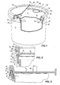
- Fig. 1 is a perspective view of a container according to the invention, shown partly in section,
- Fig. 2 is a sectional view of a top edge portion of the container with the sealing lid ready to be mounted thereon,
- Figs. 3 and 4 are corresponding views seen during the mounting of the lid,
- Fig. 5 is a corresponding view of the container- as finally closed,
- Fig. 6 is a similar view of the container as provided with a reclosing lid,
- Fig. 7 is a similar view of the container with the sealing lid removed, and
- Fig 8 is a view corresponding to Fig. 5 and showing a modified container and sealing lid assembly.
- The container shown in Figs. 1-6 comprises a
container body 2 made by injection moulding of an ordinary thermoplastic material. The interior cylindrical top wall portion of the container body is designated 4, and from an exterior annular area of this wall portion slightly below the top edge thereof projects anexterior flange portion 8 outwardly and then upwardly to a level well above the top of theinner wall portion 4, such that between the wall orflange portions annular edge groove 6. Approximately in level with the top edge of thewall 4 the interior side of theouter flange 8 has anundercut locking nose 10, above which theinner side 12 of the upstandingouter flange 8 projects upwardly and slightly outwardly inclined. - An associated sealing lid is generally designated 14 and comprises a horizontal
lid plate portion 16 having along its periphery a downwardly projectinglocking flange 18 showing anexterior locking nose 20 and anouter surface portion 22 below thenose 20 which is inclined or conical corresponding to the conicity of the containerflange surface portion 12. The lid furthermore has an upstandingannular flange 24, which is topwise extended outwardly in aportion 26 and then downwardly in an outercylindrical flange portion 28, which is adjacent its lower edge provided with an inwardly projectingnose portion 30, above which there is agroove space 32 defined between theflange portions - This
groove 32 is adapted to receive the top end of theouter container flange 8, and for cooperation with the saidnose portion 30 the outside of theflange 8 is provided with an exterior nose orundercut portion 34. - As shown in Figs. 1 and 6 the assembly may comprise an additional reclosing
lid 42 to be described in more detail below. For the mounting of the sealinglid 14 it is less important whether or not the reclosinglid 42 is present. - In Fig. 2 it is indicated that the
container member 2 is initially liquid filled to a. level above the top edge of theinternal mouth portion 4, and thesealing lid 14 is placed so as to be mountable on the container by a relative downward movement of the lid. As shown in Fig. 3 the lid may be forced downwardly by means of a centralpressing shoe 36, whereby the lid is easily brought into a position in which the outside of the dependinglid flange 18 engages theinner side 12 of theexterior container flange 8 above thenose portion 10 thereof. Once this engagement has been established the liquid in the container will no longer escape readily by the downward movement of thelid 14, but it will escape anyway because the central downpressing of thelid 14 causes thelid plate 16 to be deformed conically so as to reduce its diameter, while at the same time an increased internal pressure in the container will be able to force theexterior container flange 8 slightly outwardly. - Hereby the liquid may still escape at least until the
lid 14 reaches the relative position shown in Fig. 4, wherein the dependinglocking flange 18 of thelid 14 is initially entering theedge groove 6 of the container. At the same time or slightly earlier the outer top side of theflange 8 is engaged by thelocking nose 30, whereby theflange 28 is forced or held inwardly. To facilitate the escape of the liquid thelocking nose 30 or - as shown - the outside of theflange 8 above itsnose 34 may be provided withvertical grooves 40. - When the
locking flange 18 has reached the position shown in Fig. 4 the continued downward movement of the centralpressing shoe 36 will result in a conical deformation of the lid, as also shown in Fig. 4. By this deformation a further volume of air and liquid as present underneath the lid will be brought to escape, and only a small volume of air will remain thereafter, along the edge area of the lid. - Thereafter a final closing force is applied to the
top portion 26 of the lid edge, as shown by anarrow 38 in Fig. 4, and at the same time the pressure as exerted by the centralpressing shoe 36 is relieved. - The
final closing force 38 is applied by a circular piston (not shown), and because a relatively high force can be mechanically applied, without moderation for enabling a later manual reclosing, the interacting locking portions may be designed such that they establish a very firm locking engagement by a relatively short relative displacement of the lid. By this short movement (from Fig. 4 to Fig. 5) thenose 20 of the lid will engage under thenose portion 10 of theflange 8, and the surplus of liquid in thegroove 6 will be forced to find its way out. The general volume reduction of the container space during the final closing movement is compensated for by the central portion of the lid now being able to move upwardly, at least relative the lid edge. As a result the container may be closed so as to be practically entirely liquid filled and with thelid 14 having a usual planar appearance. - During shipping and handling of the closed container the locking engagement between the
noses groove 6 as well as theupstanding flanges locking flange 18 against edging in thegroove 6. Even the location of theactive nose 20 of the lid just outside the edge of the planar lid portion has a stabilizing effect. - In the locked position of the lid the underside of the planar lid portion abuts edgewise the top end of the
interior mouth portion 4 of the container. - As shown in Figs 1 and 6 the closed container may be provided with a reusable
top lid member 42, which is held with anose portion 44 snapping underneath the lower edge of theexterior flange 28 of thesealing lid 14. This reclosinglid 42 is designed so as to be manually removable and remountable. - The sealing
lid 14 is openable by being rupturable along an annular weakeninggroove 46 which is located such that in the closed position of the lid it follows the inner edge of the interiormouth cylinder portion 4 of the container. The lid is integrally provided with a shortupstanding pin portion 48, see Fig. 1, which is itself integrally provided with ahorizontal ring member 50 to be manually lifted for tearing off the lid along the weakening groove. In practice, however, thegroove 46 should not weaken the lid plate to the extent that already a pull in thering 50 would be sufficient to rupture the lid, and in an preferred arrangement, therefore, thepin 48 is located endwise of astrip portion 52 confined between two parallel lines constituted by respective grooves in the underside of the lid, one of the grooves maturing in theannular groove 46 while the other groove continues in anannular groove 54 located inwardly spaced from thegroove 46 such that acircular strip 56 is defined between these grooves. - When the
ring 50 is lifted thepin 48 will be caused to tilt and this initially break the weakened lid material at the end of thestrip portion 52, whereafter by further pulling in thering 50 thestrip portion 52 and thereafter theannular strip portion 56 will be torn up. This continues almost all the way round, until theinner groove 54 stops or has a local outfilling at 58, whereby a further pull in the ring and the already torn upstrip portion exterior groove 46 only, i.e. now the major lid portion itself will be torn off along the remaining part of theexterior groove 46 until the lid is completely opened and removable when the former point of junction with theinitial portion 52 is reached. - It will be appreciated that the container as thus opened will show a practically smooth interior mouth wall, as illustrated in Fig. 7, and the entire edge portion of the opened container will appear as unitary.
- It will be appreciated that during the opening of the sealing lid (irrespectively of how the lid is opened, e.g. even by cutting) any upwardly leaking liquid from the container will not overflow the top edge of the container assembly, as it will be held back by the
upstanding edge flange 24 and thus be returned to the container when the central lid portion is removed. - In Fig. 6 it is shown that the reclosing
lid 42 has a centrally depending,annular flange 60 which steps on the top side of thesealing lid 14, whereby the central closing pressure on thelid 14 by means of the pressing shoe 36 (Fig.3) may be exerted on the top side of the reclosinglid 42. Since the reclosinglid 42 is carried entirely by the sealing lid these two lids may be mounted as a preassembled unit, this being an important advantage in the filling and closing station. Even edgewise the reclosinglid 42 is resting on the sealinglid 14, viz. on theupper flange portion 26 thereof, whereby the final closing force 38 (Fig. 4) may be applied by means of an annular piston 62 (Fig. 6) pressing on the top side of the reclosinglid 42. - The possible preassembly of the two
lids lid 14 because of its non-symmetrical design with respect to the weakeninggroove 54, which conditions a nonuniform outflow resistance of the moulding material in the injection mould, in which the lid is produced, because the groove 54 (or its corresponding mould part) is not extending fully continuously all the way along the edge of the lid. - Fig. 8 shows an embodiment in which the
locking flange 18 of the sealing lid is depending not from the edge of the central lid portion, but from the outside of theupstanding edge flange 24 of the lid, and the corresponding upstandingouter flange 8 of the container is shaped in a complementary manner. In this embodiment thelocking flange 18 does not depend below the level of the central lid portion, i.e. when the lid is lowered towards the open container top the dependinglocking flange 18 will not act to collect an air cushion underneath the central portion of the lid, and the air volume collected or confined by theflange 18 of Fig. 8 will be absolutely negligible, also because the collected small volume of air between theflange 18 and theflange 24 will be "washed out" by the liquid as escaping from the container during the final phase of the lid mounting operation. - In the embodiment of Fig. 8 there is no outermost locking nose connection between the upstanding container flange and the
exterior lid flange 28, but the latter is still designed so as to support the exterior top edge of theflange 8 against any displacement outwardly, i.e. theflange 28 will contribute to theflange 8 being held in any locking engagement with thelid flange 18 despite any expanding effect on theflange 8 or- likewise - any contracting effect on theflange 24 as caused e.g. by an impact on the sealed container, whereby the sealinglid 14 tends to get deformed conically upwardly. - By any conical deformation of the central major portion of the sealing lid the
upstanding lid flange 24 and the depending lockingflange 18 will be cross sectionally influenced to carry out a tilting movement relative the edge portions of the container, and such movement may result in a lid loosening crowbar action between the various flange portions. First of all, however, the design of the said cross section according to the invention will minimize the effective crowbar action on the interacting locking nose portions, but additionally the presence of theoutermost weakening groove 46 will involve that the remaining lid material portion above the weakening groove will act as a bendable hinge portion, whereby the tilting force on the outer lid edge portions as produced by a conical deformation ofthe lid 14will be drastically reduced. - The invention is in no way limited to the embodments shown in the drawing, e.g. because the locking nose engagement between the container and the sealing lid may be located adjacent the interior side of the locking
flange 18, and the primary locking effect may even occur between nose portions of an upstanding flange of the container and one or both sides of a downwardly open groove defined by flange portions of the sealing lid. With the use of a downwardly protruding lockingflange 18 of thelid 14 this flange may be located at a still higher level than according to Fig. 8, e.g. for cooperation with a topwise arranged groove in theflange 8 of the jug. - The invention also comprises the described method whereby a sealing lid as combined or not combined with a reclosing lid is brought into a locked position on the top edge of a container member. In order to ensure an efficient escape of a trapped air volume underneath the sealing lid it may be preferable to effect the lid mounting with the lid and the container assuming a generally inclined position.
- A well suited material for the container and the sealing lid will be low pressure poly ethylene or propylene, which shows the required resiliency for the snap locking function and is otherwise suitably rigid for the general stability of the container.
Claims (2)
Priority Applications (1)
| Application Number | Priority Date | Filing Date | Title |
|---|---|---|---|
| AT81201395T ATE20719T1 (en) | 1980-12-23 | 1981-12-22 | SALES CONTAINER. |
Applications Claiming Priority (2)
| Application Number | Priority Date | Filing Date | Title |
|---|---|---|---|
| DK5491/80 | 1980-12-23 | ||
| DK549180A DK549180A (en) | 1980-12-23 | 1980-12-23 | BASKET OR FINE SHAPE FORMATIC PACKAGING WITH PRESSURE LAYER AND PROCEDURE FOR PRESSING THE LAYER |
Publications (2)
| Publication Number | Publication Date |
|---|---|
| EP0055007A1 EP0055007A1 (en) | 1982-06-30 |
| EP0055007B1 true EP0055007B1 (en) | 1986-07-16 |
Family
ID=8142889
Family Applications (1)
| Application Number | Title | Priority Date | Filing Date |
|---|---|---|---|
| EP81201395A Expired EP0055007B1 (en) | 1980-12-23 | 1981-12-22 | A sales container |
Country Status (14)
| Country | Link |
|---|---|
| US (1) | US4453646A (en) |
| EP (1) | EP0055007B1 (en) |
| JP (1) | JPS57502118A (en) |
| AT (1) | ATE20719T1 (en) |
| AU (1) | AU547413B2 (en) |
| BR (1) | BR8108929A (en) |
| DE (2) | DE8138577U1 (en) |
| DK (1) | DK549180A (en) |
| FI (1) | FI822846L (en) |
| IL (1) | IL64624A0 (en) |
| NO (1) | NO822844L (en) |
| NZ (1) | NZ199345A (en) |
| WO (1) | WO1982002183A1 (en) |
| ZA (1) | ZA818796B (en) |
Families Citing this family (57)
| Publication number | Priority date | Publication date | Assignee | Title |
|---|---|---|---|---|
| US4442949A (en) * | 1983-03-21 | 1984-04-17 | American Flange & Manufacturing Co. Inc. | Tear open closure assembly |
| SE453822B (en) * | 1985-08-16 | 1988-03-07 | Plm Ab | CONTAINER WITH TWO LIDS |
| US4671406A (en) * | 1985-11-04 | 1987-06-09 | Baer Steven H | Convertible tennis ball container |
| US4706837A (en) * | 1986-03-24 | 1987-11-17 | Inventive Packaging Corporation | Tamper-resistant package |
| US4682702A (en) * | 1986-06-27 | 1987-07-28 | Sunbeam Plastics Corporation | Tamper indicating closure |
| WO1988000559A1 (en) * | 1986-07-11 | 1988-01-28 | Sun Coast Plastics, Inc. | Removal of non-strippable articles from a mold |
| DE3765076D1 (en) * | 1986-10-13 | 1990-10-25 | Lin Pac Mouldings | PLASTIC CONTAINER UNIT. |
| US4760931A (en) * | 1986-12-22 | 1988-08-02 | Sunbeam Plastics Corporation | Safety container neck insert |
| US4923702A (en) * | 1987-07-20 | 1990-05-08 | Powell Levisky | Communion container |
| GB8725738D0 (en) * | 1987-11-03 | 1987-12-09 | Reliance Products Ltd | Cover for plastic containers |
| US4819819A (en) * | 1988-03-28 | 1989-04-11 | Robertson Jr Bertram D | Tamper-evident closure |
| FR2645125B1 (en) * | 1989-03-28 | 1991-07-26 | Simon Patrick | SEALED CLOSURE DEVICE FOR CONTAINERS AND METHOD FOR THE PRODUCTION THEREOF |
| US4942974A (en) * | 1989-06-09 | 1990-07-24 | Sealright Company, Inc. | Tamper evident container |
| GB8916523D0 (en) * | 1989-07-19 | 1989-09-06 | Mackay Murdo | Container |
| DE3933177A1 (en) * | 1989-10-04 | 1991-04-11 | Hermedicon Wolfgang Herdlicka | PLASTIC CONTAINER FOR THE DISPOSAL OF DISPOSABLE MEDICAL OBJECTS AND DEVICES |
| US5009310A (en) * | 1990-04-04 | 1991-04-23 | Finney Patrick D | Disposable container for storing and dispensing pet food |
| DE9212152U1 (en) * | 1991-10-02 | 1992-11-12 | Tueshaus Medizinische Produkte Gmbh, 4882 Velen, De | |
| US5328047A (en) * | 1992-01-06 | 1994-07-12 | North America Packaging Corporation | Double locking pail and cover for regulated materials |
| US5348549A (en) * | 1993-03-29 | 1994-09-20 | Brown Daniel R | Fluid tight medical apparatus disposal receptacle |
| GB2287019B (en) * | 1993-09-07 | 1997-04-02 | Ryford Ltd | Lidded container |
| GB9318540D0 (en) * | 1993-09-07 | 1993-10-20 | Ryford Ltd | Lidded container |
| WO1995020531A1 (en) * | 1994-01-27 | 1995-08-03 | Plastican, Inc. | Pail safety ring |
| US5452818A (en) * | 1994-04-25 | 1995-09-26 | Yost; Kenneth J. | Reusable beverage can closure |
| GB2310201B (en) * | 1995-01-30 | 1999-04-14 | Portola Packaging Inc | Fitment in combination with a machine for inserting the fitment into a container wall |
| US6464096B2 (en) | 1995-01-30 | 2002-10-15 | Portola Packaging, Inc. | Fitment having removable membrane |
| US5713484A (en) * | 1996-03-26 | 1998-02-03 | Sonoco Products Company | Two-piece plastic container and removable cover |
| US5755360A (en) * | 1996-07-11 | 1998-05-26 | Aptargroup, Inc. | Multi-material, multi-shot, injection molded dispensing closure having a removable seal |
| US5769277A (en) * | 1996-07-11 | 1998-06-23 | Aptargroup, Inc. | Dispensing closure having a force-directing removable seal |
| US6220471B1 (en) * | 1999-11-15 | 2001-04-24 | Sonoco Development, Inc. | Resealing overcap for a cylindrical container |
| DE20006093U1 (en) * | 2000-04-01 | 2000-09-14 | Jokey Plastik Gummersbach Gmbh | Plastic container with snap-on lid |
| US20020121456A1 (en) * | 2001-01-16 | 2002-09-05 | Mannion Jeffrey T. | Suspended containers |
| US7040498B2 (en) * | 2001-07-17 | 2006-05-09 | Rickman Chandler T | Wallboard mud container apparatus |
| GB0122281D0 (en) * | 2001-09-14 | 2001-11-07 | Ici Plc | A container for roller-applied paint and its use in coating procedures for rough surfaces |
| US7086545B2 (en) | 2002-01-16 | 2006-08-08 | Ajava Pinata, L.L.C. | Suspended containers |
| ITTO20020891A1 (en) * | 2002-10-14 | 2004-04-15 | Tetra Laval Holdings & Finance | SEALED PACKAGING FOR VERSABLE FOOD PRODUCTS |
| GB0226424D0 (en) * | 2002-11-12 | 2002-12-18 | Thermodynamix Thermoforming Sp | Container |
| US7413097B1 (en) | 2003-08-01 | 2008-08-19 | Portola Packaging, Inc. | Tamper-evident closure and method of making same |
| US20050061706A1 (en) * | 2003-09-19 | 2005-03-24 | Reynolds Jonathan K. | Sealed secure prescription vial apparatus and method |
| US7165306B2 (en) * | 2003-10-15 | 2007-01-23 | Frito-Lay North America, Inc. | Overcap having improved fit |
| WO2005070782A1 (en) * | 2004-01-16 | 2005-08-04 | Heyn William M | Overcap for a container |
| TWM286471U (en) * | 2005-09-09 | 2006-01-21 | Smart Ant Telecom Co Ltd | Waterproof housing |
| US8181819B2 (en) | 2006-02-23 | 2012-05-22 | Bway Corporation | Lid and container |
| US7963419B2 (en) * | 2006-02-23 | 2011-06-21 | Bway Corporation | Lid and container |
| DE102006021079B4 (en) * | 2006-03-21 | 2008-01-17 | IMPRESS Metal Packaging S.A., Crosmières | Container with closure combination |
| US7993071B2 (en) * | 2006-10-25 | 2011-08-09 | Burrell E. Clawson | Assemblies for coupling two elements and coupled assemblies |
| US7909204B2 (en) * | 2008-03-03 | 2011-03-22 | Sonoco Development, Inc. | Resealing overcap for a container |
| EP2361852A1 (en) * | 2008-05-21 | 2011-08-31 | Helen of Troy Limited | Container with sealing lid |
| US20090294322A1 (en) * | 2008-06-02 | 2009-12-03 | Baltz Kyle L | Pail with skirt and lid |
| DE102008002980A1 (en) * | 2008-08-01 | 2010-02-11 | Bertrand Crozat | Plastic container with lid |
| FR2937959A1 (en) * | 2008-10-31 | 2010-05-07 | Christian Guillot | Tamperproof cosmetic jar closing device, has tear-off lines comprising portions formed on internal and external surfaces of cap, respectively, and gripping tab provided on width of crown and permitting exertion of traction for tear-off |
| US7922028B2 (en) * | 2009-02-25 | 2011-04-12 | Rehrig Pacific Company | Pail with lid and flashed lip |
| USD734149S1 (en) | 2011-09-22 | 2015-07-14 | PBM Nutritionals, LLC | Canister cover |
| EP2948747A4 (en) | 2013-01-24 | 2016-07-27 | Pbm Nutritionals Llc | Apparatus and method for making canister and for detecting leaks for quality assurance |
| JP6484082B2 (en) * | 2015-03-30 | 2019-03-13 | 株式会社デンソーテン | Fixed structure |
| JP6631050B2 (en) * | 2015-06-30 | 2020-01-15 | 株式会社明電舎 | Electronic control unit |
| US20220024652A1 (en) * | 2019-02-26 | 2022-01-27 | Bway Corporation | Container and seal assembly |
| RU208460U1 (en) * | 2021-07-15 | 2021-12-21 | Общество с ограниченной ответственностью «Дали» | CONTAINER |
Family Cites Families (19)
| Publication number | Priority date | Publication date | Assignee | Title |
|---|---|---|---|---|
| DE1074487B (en) * | 1960-01-28 | |||
| US3117691A (en) * | 1961-04-03 | 1964-01-14 | Harold W Williams | Vials of plastic material |
| DE1189911B (en) * | 1963-09-13 | 1965-03-25 | Mauser Kg | Container |
| CH475137A (en) * | 1964-06-26 | 1969-07-15 | Albis Pack Ag | Can with a sealing membrane attached to it. |
| US3513020A (en) * | 1964-10-12 | 1970-05-19 | Leesona Corp | Method of impregnating membranes |
| FI48257C (en) * | 1965-03-25 | 1974-08-12 | Karhumuovi Oy | Plastic container with lid. |
| US3434620A (en) * | 1966-03-10 | 1969-03-25 | American Flange & Mfg | Frangible plastic closure |
| US3451586A (en) * | 1967-09-15 | 1969-06-24 | Continental Can Co | Can body guard bead for scored can ends |
| US3495746A (en) * | 1967-10-30 | 1970-02-17 | American Flange & Mfg | Plastic closures for containers and combinations |
| US3419181A (en) * | 1967-11-07 | 1968-12-31 | Continental Can Co | Score guard overcap for full open ends |
| FR1547898A (en) * | 1967-12-05 | 1968-11-29 | Stamplast Societa Per Azioni | Box with deformable walls forming a vacuum container |
| NL141453B (en) * | 1967-12-06 | 1974-03-15 | Guala Angelo Spa | CLOSURE FOR A BOTTLE. |
| SE352307B (en) * | 1968-01-03 | 1972-12-27 | R Dru | |
| CA858334A (en) * | 1968-08-09 | 1970-12-15 | I. Macdonald James | Y-flanged containers and cover members therefor |
| NO134414C (en) * | 1974-02-18 | 1976-10-06 | Odd Stenerud | |
| US3957506A (en) * | 1974-09-11 | 1976-05-18 | W. R. Grace & Co. | Catalytic water treatment to recover metal value |
| DE7431341U (en) * | 1974-09-18 | 1974-12-19 | Schmalbach Lubeca | Plastic snap-on lid |
| SE7607971L (en) * | 1976-07-13 | 1978-01-14 | Wicanders Korkfabriker Ab | DEVICE FOR CONTAINER CONNECTIONS |
| US4210258A (en) * | 1978-03-02 | 1980-07-01 | Holdt J W Von | Seal for plastic buckets and cans |
-
1980
- 1980-12-23 DK DK549180A patent/DK549180A/en not_active Application Discontinuation
-
1981
- 1981-12-21 DE DE8138577U patent/DE8138577U1/en not_active Expired
- 1981-12-21 AU AU79332/82A patent/AU547413B2/en not_active Ceased
- 1981-12-21 JP JP57500191A patent/JPS57502118A/ja active Pending
- 1981-12-21 ZA ZA818796A patent/ZA818796B/en unknown
- 1981-12-21 BR BR8108929A patent/BR8108929A/en unknown
- 1981-12-21 WO PCT/DK1981/000117 patent/WO1982002183A1/en active Application Filing
- 1981-12-21 NZ NZ199345A patent/NZ199345A/en unknown
- 1981-12-21 US US06/413,348 patent/US4453646A/en not_active Expired - Fee Related
- 1981-12-22 AT AT81201395T patent/ATE20719T1/en not_active IP Right Cessation
- 1981-12-22 EP EP81201395A patent/EP0055007B1/en not_active Expired
- 1981-12-22 DE DE8181201395T patent/DE3174946D1/en not_active Expired
- 1981-12-22 IL IL64624A patent/IL64624A0/en unknown
-
1982
- 1982-08-16 FI FI822846A patent/FI822846L/en not_active Application Discontinuation
- 1982-08-20 NO NO822844A patent/NO822844L/en unknown
Also Published As
| Publication number | Publication date |
|---|---|
| EP0055007A1 (en) | 1982-06-30 |
| DE3174946D1 (en) | 1986-08-21 |
| DK549180A (en) | 1982-06-24 |
| US4453646A (en) | 1984-06-12 |
| AU547413B2 (en) | 1985-10-17 |
| FI822846A0 (en) | 1982-08-16 |
| ZA818796B (en) | 1982-11-24 |
| BR8108929A (en) | 1982-11-30 |
| AU7933282A (en) | 1982-07-20 |
| FI822846L (en) | 1982-08-16 |
| NZ199345A (en) | 1985-12-13 |
| JPS57502118A (en) | 1982-12-02 |
| IL64624A0 (en) | 1982-03-31 |
| WO1982002183A1 (en) | 1982-07-08 |
| ATE20719T1 (en) | 1986-08-15 |
| NO822844L (en) | 1982-08-20 |
| DE8138577U1 (en) | 1984-04-05 |
Similar Documents
| Publication | Publication Date | Title |
|---|---|---|
| EP0055007B1 (en) | A sales container | |
| US4111330A (en) | Reclosable vacuum container | |
| CA2491184C (en) | Closure with tear strip | |
| US4795055A (en) | Container having a pull ring for separation and removal of a lid | |
| US4901892A (en) | Tamper evident container closure | |
| US5007231A (en) | Container | |
| US4555043A (en) | Anti-spill recloseable container | |
| US4433793A (en) | Container having frangible opening means | |
| JP4199928B2 (en) | Barrel with plastic lid | |
| US4407423A (en) | Detachable resealable closure | |
| EP0109265B1 (en) | Container with tamper-evident lid | |
| EP0245894B1 (en) | Container having a detachably fastened lid | |
| US4318493A (en) | Easy opening container | |
| MXPA04008629A (en) | Plastic lid for a can. | |
| US20050133508A1 (en) | Tamper evident lid welded to a container | |
| US4387820A (en) | Closing arrangement for packing containers | |
| KR20030051715A (en) | Container-closure arrangement | |
| US4432466A (en) | Container having closure panel including integrally formed scoop rupturable therefrom | |
| US4572399A (en) | Plastic container having inwardly formed flange | |
| US5839604A (en) | Lid having flexibly hinged wall portions and container therefor | |
| US4220249A (en) | Closing arrangement for packing containers | |
| US4165016A (en) | Easy open reclosable end unit | |
| CA1184533A (en) | Sales jug | |
| WO1998046492A1 (en) | Improved plastic bottle closure | |
| WO1979000722A1 (en) | Container with side wall,cover and tearing device produced as a unit |
Legal Events
| Date | Code | Title | Description |
|---|---|---|---|
| PUAI | Public reference made under article 153(3) epc to a published international application that has entered the european phase |
Free format text: ORIGINAL CODE: 0009012 |
|
| AK | Designated contracting states |
Designated state(s): AT BE CH DE FR GB IT NL SE |
|
| 17P | Request for examination filed |
Effective date: 19821222 |
|
| GRAA | (expected) grant |
Free format text: ORIGINAL CODE: 0009210 |
|
| AK | Designated contracting states |
Kind code of ref document: B1 Designated state(s): AT BE CH DE FR GB IT LI NL SE |
|
| PG25 | Lapsed in a contracting state [announced via postgrant information from national office to epo] |
Ref country code: NL Effective date: 19860716 Ref country code: LI Effective date: 19860716 Ref country code: IT Free format text: LAPSE BECAUSE OF FAILURE TO SUBMIT A TRANSLATION OF THE DESCRIPTION OR TO PAY THE FEE WITHIN THE PRESCRIBED TIME-LIMIT;WARNING: LAPSES OF ITALIAN PATENTS WITH EFFECTIVE DATE BEFORE 2007 MAY HAVE OCCURRED AT ANY TIME BEFORE 2007. THE CORRECT EFFECTIVE DATE MAY BE DIFFERENT FROM THE ONE RECORDED. Effective date: 19860716 Ref country code: FR Free format text: THE PATENT HAS BEEN ANNULLED BY A DECISION OF A NATIONAL AUTHORITY Effective date: 19860716 Ref country code: CH Effective date: 19860716 Ref country code: BE Effective date: 19860716 Ref country code: AT Effective date: 19860716 |
|
| REF | Corresponds to: |
Ref document number: 20719 Country of ref document: AT Date of ref document: 19860815 Kind code of ref document: T |
|
| PG25 | Lapsed in a contracting state [announced via postgrant information from national office to epo] |
Ref country code: SE Effective date: 19860731 |
|
| REF | Corresponds to: |
Ref document number: 3174946 Country of ref document: DE Date of ref document: 19860821 |
|
| REG | Reference to a national code |
Ref country code: CH Ref legal event code: PL |
|
| EN | Fr: translation not filed | ||
| NLV1 | Nl: lapsed or annulled due to failure to fulfill the requirements of art. 29p and 29m of the patents act | ||
| PLBE | No opposition filed within time limit |
Free format text: ORIGINAL CODE: 0009261 |
|
| STAA | Information on the status of an ep patent application or granted ep patent |
Free format text: STATUS: NO OPPOSITION FILED WITHIN TIME LIMIT |
|
| 26N | No opposition filed | ||
| GBPC | Gb: european patent ceased through non-payment of renewal fee | ||
| PG25 | Lapsed in a contracting state [announced via postgrant information from national office to epo] |
Ref country code: DE Effective date: 19870901 |
|
| PG25 | Lapsed in a contracting state [announced via postgrant information from national office to epo] |
Ref country code: GB Free format text: LAPSE BECAUSE OF NON-PAYMENT OF DUE FEES Effective date: 19881121 |