EP0052282A2 - Apparatus for use in an electrochemical cell and electrochemical cell - Google Patents
Apparatus for use in an electrochemical cell and electrochemical cell Download PDFInfo
- Publication number
- EP0052282A2 EP0052282A2 EP81109223A EP81109223A EP0052282A2 EP 0052282 A2 EP0052282 A2 EP 0052282A2 EP 81109223 A EP81109223 A EP 81109223A EP 81109223 A EP81109223 A EP 81109223A EP 0052282 A2 EP0052282 A2 EP 0052282A2
- Authority
- EP
- European Patent Office
- Prior art keywords
- accordance
- container
- polymer solution
- electrochemical cell
- electrode
- Prior art date
- Legal status (The legal status is an assumption and is not a legal conclusion. Google has not performed a legal analysis and makes no representation as to the accuracy of the status listed.)
- Granted
Links
Images
Classifications
-
- H—ELECTRICITY
- H01—ELECTRIC ELEMENTS
- H01M—PROCESSES OR MEANS, e.g. BATTERIES, FOR THE DIRECT CONVERSION OF CHEMICAL ENERGY INTO ELECTRICAL ENERGY
- H01M50/00—Constructional details or processes of manufacture of the non-active parts of electrochemical cells other than fuel cells, e.g. hybrid cells
- H01M50/40—Separators; Membranes; Diaphragms; Spacing elements inside cells
- H01M50/489—Separators, membranes, diaphragms or spacing elements inside the cells, characterised by their physical properties, e.g. swelling degree, hydrophilicity or shut down properties
-
- Y—GENERAL TAGGING OF NEW TECHNOLOGICAL DEVELOPMENTS; GENERAL TAGGING OF CROSS-SECTIONAL TECHNOLOGIES SPANNING OVER SEVERAL SECTIONS OF THE IPC; TECHNICAL SUBJECTS COVERED BY FORMER USPC CROSS-REFERENCE ART COLLECTIONS [XRACs] AND DIGESTS
- Y02—TECHNOLOGIES OR APPLICATIONS FOR MITIGATION OR ADAPTATION AGAINST CLIMATE CHANGE
- Y02E—REDUCTION OF GREENHOUSE GAS [GHG] EMISSIONS, RELATED TO ENERGY GENERATION, TRANSMISSION OR DISTRIBUTION
- Y02E60/00—Enabling technologies; Technologies with a potential or indirect contribution to GHG emissions mitigation
- Y02E60/10—Energy storage using batteries
Definitions
- This invention relates to separators for use in electrochemical cells and, in particular, for use in electrochemical cells having a zinc electrode.
- the cycle life of alkaline batteries employing zinc electrodes is limited by a number of factors.
- One primary factor is shorting of the battery electrodes which results from the growth of zinc dendrites. These dendrites produce tree-like conductive branches which eventually penetrate the battery separator to - provide a conductive path between positive and negative electrodes, thereby shorting same.
- Another factor limiting battery life is so called "shape change" of the zinc electrode. Shape change is the phenomenon of movement of the zinc active material from the electrode edges to the electrode center, thereby significantly reducing the electrode surface ' area available for electrochemical reaction.
- the degree of dendritic growth and the degree of shape change occurring in an alkaline battery are a function of the battery separator.
- Conventional battery separators typically comprise one or more layers which are selected to be compatible with the cell electrolyte. These layers are also selected to be sufficiently permeable to allow the passage of electrolyte ions, but not so highly permeable as to readily permit the passage of other materials, e.g., electrode derived conductive substances.
- Separators of this type usually contain at least one layer of membranous material (i.e., a material having a permeability of about Sx10 -3 mole/(mi-n x in 2 ) or less.
- a typical membranous material might be cellophane.
- Another type of membranous material might be the material disclosed in U.S. patent 3,351,495. Such membranous materials are found to significantly inhibit dendritic growth but are not as effective in inhibiting electrode shape change which still can occur and eventually result in battery failure.
- separator comprises a blend of a polyamide (e.g., Elvamides), a significantly lower pore size polymeric constituent (e.g., polyethylene oxide) and a zinc reactive material (e.g., cerium dioxide).
- a polyamide e.g., Elvamides
- a significantly lower pore size polymeric constituent e.g., polyethylene oxide
- a zinc reactive material e.g., cerium dioxide
- separators described above have provided a degree of extended battery life, research is still being conducted for separators which can extend battery life still further.
- a separator construction comprising a container having opposing sides each comprised of a layer of solid microporous material and a liquid polymer solution situated in the space between the container layers.
- the container layers are disposed adjacent to the electrode of an electrochemical cell so that there is created at least a layer of solution and a layer of solid microporous material outward of the electrode surfaces.
- the polymer solution acts as relatively a low permeability (i.e., less than about 5x10 -4 mole/(min in 2 ) membranous layer preventing dendritic growth, while the solid microporous material acts as a relatively high permeability (i.e., greater than about 5x10 -4 mole/min - in 2 ) layer inhibiting shape change.
- Useable solid microporous materials are those which are mechanically and chemically stable in the cell environment, permit the desired degree of ionic flow and are able to support the polymer solution.
- the latter in turn, is of a type which does not precipitate in the cell environment, is useable without detriment to cell performance and is incapable of dissolving the solid microporous support material.
- a separator 1 comprises layers 2 of solid microporous material.
- the layers . 2 form opposite sides of a container defining a containment or reservoir region 3 for receiving a membranous liquid polymer solution 4.
- an electrode 5 Disposed within the polymer solution and in adjacent relationship to the layers 2 is an electrode 5 which typically might be the negative zinc electrode of a nickel-zinc alkaline battery.
- a connecting tab 6 extends outward from the electrode 5 between the layers 2.
- the interface regions 7 between the layers 2 and tab 6 are sealed so that the formed container and, therefore, the region 3 are fully closed to inhibit flow of the solution 4 from the region.
- FIG. 2 An alternate construction might be as shown in FIG. 2 wherein the sealed layers 2' of the separator 1' form opposite sides of a container defining a fully closed containment region 3'.
- one of the layers 2' is disposed against the flat surfaces of the electrode 5' and is'sealed to the periphery of such surfaces.
- This layer is also sealed to the electrode tab 6' at the interfaces 7'.
- FIG. 3 Another separator construction night be as shown in FIG. 3 wherein the separators 1" and 1"' comprising respective layers 2" and 2"' form two separate containers holding corresponding liquid polymer solutions 4" and 4"'.
- the separators 1" and 1"' comprising respective layers 2" and 2"' form two separate containers holding corresponding liquid polymer solutions 4" and 4"'.
- one layer of each container is adjacent and sealed to the periphery of one of the surfaces of the electrode 5", and neither container extends to the electrode tab 6".
- FIGS. 1 to 3 show the polymer solution as free .flowing
- the solution can also be disposed in its respective container in an immobilized state as by incorporating the solution in a bibulous or porous support material and disposing same in the container.
- support materials for this purpose might be non-woven polyamides, non-woven polypropylene rayon felt, cotton-batting, asbestos matting and potassium titanate papers.
- the microporous layers can be comprised of an organic or inorganic material capable of providing chemical and mechanical stability for the separator in.the electrochemical cell environment.
- the layers should be capable of providing the desired degree of ionic flow, while also compatibly supporting the polymer solution.
- the layers are in the form of a microporous polymer based film having a substantially uniform pore distribution.
- Suitable organic microporous polymer films are nylon, polyethylene, polypropylene and polyvinyl chloride, while suitable inorganic microporous films are CeO 2 , ZrO 2 , Alumina potassium titanate, etc.
- the polymer solution should, in general, be compatible with the cell environment and resistant to oxidation.
- the solution should also be insoluble in the cell electrolyte and not precipitate in the cell environment. Furthermore, the solution should be incapable of affecting the material of the microporous layers.
- the solvent for the solution should be the same as that employed in the electrolyte of the electrochemical cell.
- Preferable polymers for the solution are hydrophylic polymers which readily go into solution and have a relatively low internal resistance to electrolyte flow. Suitable polymers meeting these requirements are cellulosic polymers, vinyl acetate, polyvinyl alcohol, and polyethylene oxide.
- a polymer solution found useable with a nylon based film as the microporous layer is an aqueous solution of polyethylene oxide.
- a further solution found useable with such films is an aqueous solution of polyvinyl alcohol, the latter being combined with a cross-linking constituent to increase chemical stability of the solution.
- the microporous layers of the separator of the invention function to contain the polymer solution while also acting to uniformly distribute the ionic flow.
- the polymer solution functions as a membranous layer which allows ready flow of the electrolyte ions, while retarding flow of electrode originating solid materials and ions.
- the result is an overall separator which prevents dendritic growth in the electrochemical cell, while simultaneously inhibiting shape change of the electrode.
- the polymer solution provides the additional function of reducing current density differences which arise due to any shape change that might occur in the associated electrode.
- the liquid solution redistributes itself as a result of such shape change, becoming thicker in areas of the electrode which have become thinner (usually the electrode edges) and thinner in areas which have become thicker (usually the electrode center). This redistribution effect also acts to reduce any pressure created between the associated electrode and its adjacent electrodes as a result of shape change.
- the following table illustrates the operation of nickel zinc cells employing separator configurations in * accordance with the invention and, for comparison, provides performance data of cells employing commercially available separators (i.e., items 1 and 2).
- the separator comprised a microporous nylon based film.
- the polymer solution was a polyvinyl alcohol dissolved in water.
- the polyvinyl alcohol was a 99-100% hydrolyzed polymer sold by J.T. Baker Chemical Company and the concentration of the polymer was 10% of the solution by weight.
- the microporous film was prepared by blending a polyamide polymer sold under the name Elvamide 8064 (manufactured by E. I. DuPont), a polyolefin oxide sold under the trade name Polyox WS R 301 and having a molecular weight of 4,000,000, cerium dioxide and a wetting agent sold under the trade name Victawet.
- the blend contained the following amounts of these constituents.
- Example 1 The procedure of Example 1 was followed utilizing a polyvinyl alcohol which was 85-89% hydrolyzed and a solution thickness of about 1/16 of an inch. Cycle life of the cell was 298 cycles.
- Example 1 The procedure of Example 1 was followed utilizing a 99-100% hydrolyzed polyvinyl alcohol mixed with boric acid and Dimethylol urea, each being about 10% by weight of the alcohol. Both the boric acid and dimethylol urea served as crosslinking agents and increased chemical stability of the solution. The thickness of the solution layer was about .04 inches. Cycle life of the cell was 440 cycles.
- Example 1 The procedure of Example 1 was followed using as the polymer a polyethylene oxide which is sold under the trade name Polyox WSR 301 and which has a molecular weight of 4,000,000.
- the concentration of polyethylene oxide was about 5% by weight of the acquous solution and the thickness of the solution layer was 1/16 of an inch. Cycle life of the cell was 310 cycles.
- the separator may contain multiple solid microporous layers akin to the layer 2 and the layer 2 may further comprise different types of microporous materials which are heat sealed to form the composite container.
Abstract
Description
- This invention relates to separators for use in electrochemical cells and, in particular, for use in electrochemical cells having a zinc electrode.
- As is known, the cycle life of alkaline batteries employing zinc electrodes such as, for example, nickel-zinc, s'ilver-zinc and manganese dioxide-zinc, is limited by a number of factors. One primary factor is shorting of the battery electrodes which results from the growth of zinc dendrites. These dendrites produce tree-like conductive branches which eventually penetrate the battery separator to - provide a conductive path between positive and negative electrodes, thereby shorting same. Another factor limiting battery life is so called "shape change" of the zinc electrode. Shape change is the phenomenon of movement of the zinc active material from the electrode edges to the electrode center, thereby significantly reducing the electrode surface 'area available for electrochemical reaction.
- As is known, the degree of dendritic growth and the degree of shape change occurring in an alkaline battery are a function of the battery separator. Conventional battery separators typically comprise one or more layers which are selected to be compatible with the cell electrolyte. These layers are also selected to be sufficiently permeable to allow the passage of electrolyte ions, but not so highly permeable as to readily permit the passage of other materials, e.g., electrode derived conductive substances. Separators of this type usually contain at least one layer of membranous material (i.e., a material having a permeability of about Sx10-3 mole/(mi-n x in2) or less. A typical membranous material might be cellophane. Another type of membranous material might be the material disclosed in U.S. patent 3,351,495. Such membranous materials are found to significantly inhibit dendritic growth but are not as effective in inhibiting electrode shape change which still can occur and eventually result in battery failure.
- . A further separator construction has been proposed wherein the separator comprises a blend of a polyamide (e.g., Elvamides), a significantly lower pore size polymeric constituent (e.g., polyethylene oxide) and a zinc reactive material (e.g., cerium dioxide). In this separator, while the polymeric constituent acts to inhibit dendritic growth akin to the above-described membranous materials, the polyamide constituent provides sufficient permeability to significantly retard shape change. The resultant separator is thus said to prevent both zinc dendritic growth and electrode shape change.
- While the separators described above have provided a degree of extended battery life, research is still being conducted for separators which can extend battery life still further.
- It is an object of the present invention to provide a separator for an alkaline battery which enables longer cycle life than heretofore obtainable.
- It is further object of the present invention to provide an alkaline battery separator which further retards dendritic growth and electrode shape change.
- In accordance with the principles of the present invention, the above and other objectives are realized in a separator construction comprising a container having opposing sides each comprised of a layer of solid microporous material and a liquid polymer solution situated in the space between the container layers. In use, the container layers are disposed adjacent to the electrode of an electrochemical cell so that there is created at least a layer of solution and a layer of solid microporous material outward of the electrode surfaces. The polymer solution acts as relatively a low permeability (i.e., less than about 5x10⁻⁴ mole/(min in2) membranous layer preventing dendritic growth, while the solid microporous material acts as a relatively high permeability (i.e., greater than about 5x10⁻⁴ mole/min - in2) layer inhibiting shape change.
- Useable solid microporous materials are those which are mechanically and chemically stable in the cell environment, permit the desired degree of ionic flow and are able to support the polymer solution. The latter, in turn, is of a type which does not precipitate in the cell environment, is useable without detriment to cell performance and is incapable of dissolving the solid microporous support material.
- The above and other features and aspects of the present invention will become more apparent upon reading the following detailed description in conjunction with the accompanying drawings in which:
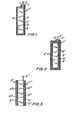
- FIG. 1 depicts a first separator construction in accordance with the principles of the present invention; and
- FIG. 2 depicts a second separator construction in accordance with the principles of the present invention; and
- FIG. 3 depicts a third separator construction in accordance with the principles of the present invention.
- In FIG. 1, a separator 1 comprises
layers 2 of solid microporous material. Thelayers .2 form opposite sides of a container defining a containment orreservoir region 3 for receiving a membranousliquid polymer solution 4. Disposed within the polymer solution and in adjacent relationship to thelayers 2 is anelectrode 5 which typically might be the negative zinc electrode of a nickel-zinc alkaline battery. A connecting tab 6 extends outward from theelectrode 5 between thelayers 2. The interface regions 7 between thelayers 2 and tab 6 are sealed so that the formed container and, therefore, theregion 3 are fully closed to inhibit flow of thesolution 4 from the region. - An alternate construction might be as shown in FIG. 2 wherein the sealed layers 2' of the separator 1' form opposite sides of a container defining a fully closed containment region 3'. In this case, one of the layers 2' is disposed against the flat surfaces of the electrode 5' and is'sealed to the periphery of such surfaces. This layer is also sealed to the electrode tab 6' at the interfaces 7'. There is thus formed outward of the electrode 5' a layer of microporous material 2', a layer of liquid polymer solution 4' and a further layer of microporous material 2', as opposed to the configuration of FIG. 1 wherein there is only a layer of
liquid polymer solution 4 and a layer ofmicroporous material 2 outward of the electrode surfaces. - Another separator construction night be as shown in FIG. 3 wherein the separators 1" and 1"' comprising
respective layers 2" and 2"' form two separate containers holding correspondingliquid polymer solutions 4" and 4"'. In this configuration, one layer of each container is adjacent and sealed to the periphery of one of the surfaces of theelectrode 5", and neither container extends to the electrode tab 6". - While FIGS. 1 to 3 show the polymer solution as free .flowing, the solution can also be disposed in its respective container in an immobilized state as by incorporating the solution in a bibulous or porous support material and disposing same in the container. Typical, support materials for this purpose might be non-woven polyamides, non-woven polypropylene rayon felt, cotton-batting, asbestos matting and potassium titanate papers.
- In general, the microporous layers can be comprised of an organic or inorganic material capable of providing chemical and mechanical stability for the separator in.the electrochemical cell environment. Furthermore, the layers should be capable of providing the desired degree of ionic flow, while also compatibly supporting the polymer solution. Preferably, the layers are in the form of a microporous polymer based film having a substantially uniform pore distribution. Suitable organic microporous polymer films are nylon, polyethylene, polypropylene and polyvinyl chloride, while suitable inorganic microporous films are CeO2, ZrO2, Alumina potassium titanate, etc.
- The polymer solution should, in general, be compatible with the cell environment and resistant to oxidation. The solution should also be insoluble in the cell electrolyte and not precipitate in the cell environment. Furthermore, the solution should be incapable of affecting the material of the microporous layers. Preferably, the solvent for the solution should be the same as that employed in the electrolyte of the electrochemical cell. Preferable polymers for the solution are hydrophylic polymers which readily go into solution and have a relatively low internal resistance to electrolyte flow. Suitable polymers meeting these requirements are cellulosic polymers, vinyl acetate, polyvinyl alcohol, and polyethylene oxide.
- A polymer solution found useable with a nylon based film as the microporous layer is an aqueous solution of polyethylene oxide. A further solution found useable with such films is an aqueous solution of polyvinyl alcohol, the latter being combined with a cross-linking constituent to increase chemical stability of the solution.
- As above-indicated, the microporous layers of the separator of the invention function to contain the polymer solution while also acting to uniformly distribute the ionic flow. The polymer solution, on the other hand, functions as a membranous layer which allows ready flow of the electrolyte ions, while retarding flow of electrode originating solid materials and ions. The result is an overall separator which prevents dendritic growth in the electrochemical cell, while simultaneously inhibiting shape change of the electrode.
- The polymer solution provides the additional function of reducing current density differences which arise due to any shape change that might occur in the associated electrode. Thus, the liquid solution redistributes itself as a result of such shape change, becoming thicker in areas of the electrode which have become thinner (usually the electrode edges) and thinner in areas which have become thicker (usually the electrode center). This redistribution effect also acts to reduce any pressure created between the associated electrode and its adjacent electrodes as a result of shape change.
- The following table illustrates the operation of nickel zinc cells employing separator configurations in* accordance with the invention and, for comparison, provides performance data of cells employing commercially available separators (i.e., items 1 and 2).

- As can be seen from Table I, cells employing separators in accord with the invention exhibited a cycle life of 2 to 2.5 times that exhibited by cells with commercial separators under the same charge and discharge test conditions.
- The following Examples further illustrate specific separators constructed in accordance with the invention.
- . In this example, the separator comprised a microporous nylon based film. The polymer solution was a polyvinyl alcohol dissolved in water. The polyvinyl alcohol was a 99-100% hydrolyzed polymer sold by J.T. Baker Chemical Company and the concentration of the polymer was 10% of the solution by weight.
- The microporous film was prepared by blending a polyamide polymer sold under the name Elvamide 8064 (manufactured by E. I. DuPont), a polyolefin oxide sold under the trade name Polyox WSR 301 and having a molecular weight of 4,000,000, cerium dioxide and a wetting agent sold under the trade name Victawet. The blend contained the following amounts of these constituents.
-
- 60% by weight Elvamide 8064
- 20% by weight Polyox WSR-301
- 12% by weight Victawet
- 8% by weight cerium dioxide
- Two layers of the film were heat sealed to form a sleeve which was situated over the zinc electrode of a Ni-Zn cell. The lower edges of the layers were then heat sealed to form an enclosed bag. The aqueous polyvinyl alcohol solution was then placed into the bag encompassing the electrode, the thickness of the solution being about 1/8 of an inch. The Ni-Zn cell was then life-cycle tested under normal conditions. Cycle life of the cell was 286 cycles.
- The procedure of Example 1 was followed utilizing a polyvinyl alcohol which was 85-89% hydrolyzed and a solution thickness of about 1/16 of an inch. Cycle life of the cell was 298 cycles.
- The procedure of Example 1 was followed utilizing a 99-100% hydrolyzed polyvinyl alcohol mixed with boric acid and Dimethylol urea, each being about 10% by weight of the alcohol. Both the boric acid and dimethylol urea served as crosslinking agents and increased chemical stability of the solution. The thickness of the solution layer was about .04 inches. Cycle life of the cell was 440 cycles.
- The procedure of Example 1 was followed using as the polymer a polyethylene oxide which is sold under the trade name Polyox WSR 301 and which has a molecular weight of 4,000,000. The concentration of polyethylene oxide was about 5% by weight of the acquous solution and the thickness of the solution layer was 1/16 of an inch. Cycle life of the cell was 310 cycles.
- In all cases, it is understood that the above-described arrangements are merely illustrative of the many possible specific embodiments which represent applications of the present invention. Numerous and varied other arrangements can readily be devised in accordance with the principles of the present invention without departing from the spirit and scope of the invention. Thus, for example, the separator may contain multiple solid microporous layers akin to the
layer 2 and thelayer 2 may further comprise different types of microporous materials which are heat sealed to form the composite container.
Claims (50)
Applications Claiming Priority (2)
| Application Number | Priority Date | Filing Date | Title |
|---|---|---|---|
| US06/204,645 US4310608A (en) | 1980-11-06 | 1980-11-06 | Separator incorporating liquid layer |
| US204645 | 1988-06-10 |
Publications (3)
| Publication Number | Publication Date |
|---|---|
| EP0052282A2 true EP0052282A2 (en) | 1982-05-26 |
| EP0052282A3 EP0052282A3 (en) | 1982-09-01 |
| EP0052282B1 EP0052282B1 (en) | 1985-09-18 |
Family
ID=22758821
Family Applications (1)
| Application Number | Title | Priority Date | Filing Date |
|---|---|---|---|
| EP81109223A Expired EP0052282B1 (en) | 1980-11-06 | 1981-10-29 | Apparatus for use in an electrochemical cell and electrochemical cell |
Country Status (4)
| Country | Link |
|---|---|
| US (1) | US4310608A (en) |
| EP (1) | EP0052282B1 (en) |
| JP (1) | JPS57105959A (en) |
| DE (1) | DE3172362D1 (en) |
Cited By (2)
| Publication number | Priority date | Publication date | Assignee | Title |
|---|---|---|---|---|
| GB2160705A (en) * | 1984-06-22 | 1985-12-24 | Sanyo Electric Co | Nonaqueous electrolyte cell |
| EP0195684A2 (en) * | 1985-03-22 | 1986-09-24 | Scimat Limited | Protected electrode material |
Families Citing this family (4)
| Publication number | Priority date | Publication date | Assignee | Title |
|---|---|---|---|---|
| US4592973A (en) * | 1983-10-05 | 1986-06-03 | Castle Technology Corp. | Supported liquid membrane electrochemical separators |
| US6203941B1 (en) * | 1998-12-18 | 2001-03-20 | Eveready Battery Company, Inc. | Formed in situ separator for a battery |
| US6858045B2 (en) * | 2002-11-29 | 2005-02-22 | Praxair Technology, Inc. | Method of manufacturing an electrolytic cell |
| US20140224465A1 (en) * | 2013-02-12 | 2014-08-14 | Eric Andrasi | Hydrophilic polymer thermal barrier system |
Citations (7)
| Publication number | Priority date | Publication date | Assignee | Title |
|---|---|---|---|---|
| US2853537A (en) * | 1956-11-30 | 1958-09-23 | Sidney A Corren | Sheet electrolyte for batteries |
| US3351495A (en) * | 1966-11-22 | 1967-11-07 | Grace W R & Co | Battery separator |
| US3558358A (en) * | 1969-03-10 | 1971-01-26 | Eagle Picher Ind Inc | Nickel-zinc secondary battery |
| DE2263402A1 (en) * | 1971-12-16 | 1973-08-09 | Comp Generale Electricite | ACCUMULATOR WITH ALKALINE ELECTROLYTE AND METHOD OF ITS PRODUCTION |
| US3784413A (en) * | 1969-07-22 | 1974-01-08 | Matsushita Electric Ind Co Ltd | Dry cells |
| DE2847464A1 (en) * | 1978-11-02 | 1980-05-14 | Varta Batterie | SEPARATOR FOR ELECTROCHEMICAL HIGH TEMPERATURE CELLS |
| US4215186A (en) * | 1979-02-26 | 1980-07-29 | Jaeger Ben E | Battery plate separator and battery containing the same |
Family Cites Families (2)
| Publication number | Priority date | Publication date | Assignee | Title |
|---|---|---|---|---|
| US3013100A (en) * | 1957-05-02 | 1961-12-12 | Yardney International Corp | Diaphragm for electrolytic processes and method of making same |
| US4218275A (en) * | 1978-02-03 | 1980-08-19 | Olin Corporation | Method of sealing separators for electrolytic cells for alkali metal chloride brines |
-
1980
- 1980-11-06 US US06/204,645 patent/US4310608A/en not_active Expired - Lifetime
-
1981
- 1981-10-29 DE DE8181109223T patent/DE3172362D1/en not_active Expired
- 1981-10-29 EP EP81109223A patent/EP0052282B1/en not_active Expired
- 1981-11-05 JP JP56176560A patent/JPS57105959A/en active Pending
Patent Citations (7)
| Publication number | Priority date | Publication date | Assignee | Title |
|---|---|---|---|---|
| US2853537A (en) * | 1956-11-30 | 1958-09-23 | Sidney A Corren | Sheet electrolyte for batteries |
| US3351495A (en) * | 1966-11-22 | 1967-11-07 | Grace W R & Co | Battery separator |
| US3558358A (en) * | 1969-03-10 | 1971-01-26 | Eagle Picher Ind Inc | Nickel-zinc secondary battery |
| US3784413A (en) * | 1969-07-22 | 1974-01-08 | Matsushita Electric Ind Co Ltd | Dry cells |
| DE2263402A1 (en) * | 1971-12-16 | 1973-08-09 | Comp Generale Electricite | ACCUMULATOR WITH ALKALINE ELECTROLYTE AND METHOD OF ITS PRODUCTION |
| DE2847464A1 (en) * | 1978-11-02 | 1980-05-14 | Varta Batterie | SEPARATOR FOR ELECTROCHEMICAL HIGH TEMPERATURE CELLS |
| US4215186A (en) * | 1979-02-26 | 1980-07-29 | Jaeger Ben E | Battery plate separator and battery containing the same |
Cited By (3)
| Publication number | Priority date | Publication date | Assignee | Title |
|---|---|---|---|---|
| GB2160705A (en) * | 1984-06-22 | 1985-12-24 | Sanyo Electric Co | Nonaqueous electrolyte cell |
| EP0195684A2 (en) * | 1985-03-22 | 1986-09-24 | Scimat Limited | Protected electrode material |
| EP0195684A3 (en) * | 1985-03-22 | 1988-01-13 | Raychem Limited | Protected electrode material |
Also Published As
| Publication number | Publication date |
|---|---|
| JPS57105959A (en) | 1982-07-01 |
| DE3172362D1 (en) | 1985-10-24 |
| EP0052282B1 (en) | 1985-09-18 |
| EP0052282A3 (en) | 1982-09-01 |
| US4310608A (en) | 1982-01-12 |
Similar Documents
| Publication | Publication Date | Title |
|---|---|---|
| CN104051697B (en) | There is the barrier film of porous coating and the electrochemical appliance containing described barrier film | |
| US5910366A (en) | Thin film composite membrane as battery separator | |
| US4599157A (en) | Oxygen permeable membrane | |
| JPH02288164A (en) | Metal-air battery and its anode | |
| US6743548B2 (en) | Silver-zinc alkaline rechargeable battery (stacking order) | |
| SE464998B (en) | AIR DEPOLARIZED CELL WITH METAL ANOD | |
| KR20200034470A (en) | Separator and electrochemical device containing the same | |
| US3655449A (en) | Dry cell comprising a separator composed of three layers | |
| EP0052282A2 (en) | Apparatus for use in an electrochemical cell and electrochemical cell | |
| US4304828A (en) | Zinc electrode | |
| US3272653A (en) | Electrode assembly | |
| KR20210022098A (en) | Separation membrane, electrochemical device including the separation membrane, and method of manufacturing the separation membrane | |
| US4034144A (en) | Separator for secondary alkaline batteries | |
| JP3473929B2 (en) | Adhesive tape for lithium ion batteries | |
| EP0077030A1 (en) | Electrochemical cell with improved separator system | |
| US4804598A (en) | Separator systems for silver-iron batteries | |
| Skelton et al. | Improved silver/zinc secondary cells for underwater applications | |
| US3450566A (en) | Electrode assembly with accordion wrap separator | |
| US3022367A (en) | Separator for electric batteries | |
| JP2014127440A (en) | Separator for lithium ion secondary battery with process film, and manufacturing method therefor | |
| JPS61179061A (en) | Enclosed type lead storage battery | |
| KR20230039174A (en) | Pouch film for secondary battery and Secondary battery comprising the same | |
| JP2782911B2 (en) | Battery | |
| JP2023151353A (en) | Separator for power storage device and power storage device | |
| JPS61263043A (en) | Organic electrolyte battery |
Legal Events
| Date | Code | Title | Description |
|---|---|---|---|
| PUAI | Public reference made under article 153(3) epc to a published international application that has entered the european phase |
Free format text: ORIGINAL CODE: 0009012 |
|
| AK | Designated contracting states |
Designated state(s): DE FR GB |
|
| PUAL | Search report despatched |
Free format text: ORIGINAL CODE: 0009013 |
|
| AK | Designated contracting states |
Designated state(s): DE FR GB |
|
| 17P | Request for examination filed |
Effective date: 19821004 |
|
| GRAA | (expected) grant |
Free format text: ORIGINAL CODE: 0009210 |
|
| AK | Designated contracting states |
Designated state(s): DE FR GB |
|
| REF | Corresponds to: |
Ref document number: 3172362 Country of ref document: DE Date of ref document: 19851024 |
|
| ET | Fr: translation filed | ||
| PLBE | No opposition filed within time limit |
Free format text: ORIGINAL CODE: 0009261 |
|
| STAA | Information on the status of an ep patent application or granted ep patent |
Free format text: STATUS: NO OPPOSITION FILED WITHIN TIME LIMIT |
|
| 26N | No opposition filed | ||
| PG25 | Lapsed in a contracting state [announced via postgrant information from national office to epo] |
Ref country code: GB Effective date: 19881029 |
|
| PG25 | Lapsed in a contracting state [announced via postgrant information from national office to epo] |
Ref country code: FR Free format text: LAPSE BECAUSE OF NON-PAYMENT OF DUE FEES Effective date: 19890630 |
|
| PG25 | Lapsed in a contracting state [announced via postgrant information from national office to epo] |
Ref country code: DE Effective date: 19890701 |
|
| GBPC | Gb: european patent ceased through non-payment of renewal fee | ||
| REG | Reference to a national code |
Ref country code: FR Ref legal event code: ST |