EP0046965A1 - Method and device for determining mass flow dynamically and independent of fluid density - Google Patents
Method and device for determining mass flow dynamically and independent of fluid density Download PDFInfo
- Publication number
- EP0046965A1 EP0046965A1 EP81106568A EP81106568A EP0046965A1 EP 0046965 A1 EP0046965 A1 EP 0046965A1 EP 81106568 A EP81106568 A EP 81106568A EP 81106568 A EP81106568 A EP 81106568A EP 0046965 A1 EP0046965 A1 EP 0046965A1
- Authority
- EP
- European Patent Office
- Prior art keywords
- flow
- fault
- disturbance
- measure
- resistance
- Prior art date
- Legal status (The legal status is an assumption and is not a legal conclusion. Google has not performed a legal analysis and makes no representation as to the accuracy of the status listed.)
- Granted
Links
Images


Classifications
-
- G—PHYSICS
- G01—MEASURING; TESTING
- G01F—MEASURING VOLUME, VOLUME FLOW, MASS FLOW OR LIQUID LEVEL; METERING BY VOLUME
- G01F1/00—Measuring the volume flow or mass flow of fluid or fluent solid material wherein the fluid passes through a meter in a continuous flow
- G01F1/05—Measuring the volume flow or mass flow of fluid or fluent solid material wherein the fluid passes through a meter in a continuous flow by using mechanical effects
- G01F1/20—Measuring the volume flow or mass flow of fluid or fluent solid material wherein the fluid passes through a meter in a continuous flow by using mechanical effects by detection of dynamic effects of the flow
- G01F1/32—Measuring the volume flow or mass flow of fluid or fluent solid material wherein the fluid passes through a meter in a continuous flow by using mechanical effects by detection of dynamic effects of the flow using swirl flowmeters
- G01F1/3209—Measuring the volume flow or mass flow of fluid or fluent solid material wherein the fluid passes through a meter in a continuous flow by using mechanical effects by detection of dynamic effects of the flow using swirl flowmeters using Karman vortices
- G01F1/3218—Measuring the volume flow or mass flow of fluid or fluent solid material wherein the fluid passes through a meter in a continuous flow by using mechanical effects by detection of dynamic effects of the flow using swirl flowmeters using Karman vortices bluff body design
-
- G—PHYSICS
- G01—MEASURING; TESTING
- G01F—MEASURING VOLUME, VOLUME FLOW, MASS FLOW OR LIQUID LEVEL; METERING BY VOLUME
- G01F1/00—Measuring the volume flow or mass flow of fluid or fluent solid material wherein the fluid passes through a meter in a continuous flow
- G01F1/05—Measuring the volume flow or mass flow of fluid or fluent solid material wherein the fluid passes through a meter in a continuous flow by using mechanical effects
- G01F1/20—Measuring the volume flow or mass flow of fluid or fluent solid material wherein the fluid passes through a meter in a continuous flow by using mechanical effects by detection of dynamic effects of the flow
- G01F1/28—Measuring the volume flow or mass flow of fluid or fluent solid material wherein the fluid passes through a meter in a continuous flow by using mechanical effects by detection of dynamic effects of the flow by drag-force, e.g. vane type or impact flowmeter
-
- G—PHYSICS
- G01—MEASURING; TESTING
- G01F—MEASURING VOLUME, VOLUME FLOW, MASS FLOW OR LIQUID LEVEL; METERING BY VOLUME
- G01F1/00—Measuring the volume flow or mass flow of fluid or fluent solid material wherein the fluid passes through a meter in a continuous flow
- G01F1/76—Devices for measuring mass flow of a fluid or a fluent solid material
- G01F1/86—Indirect mass flowmeters, e.g. measuring volume flow and density, temperature or pressure
Definitions
- the invention relates to a method for the dynamic and density-independent determination of the mass flow of fluids and devices for carrying out this method.
- the speed and dynamic pressure of the fluid are recorded at a single fault body introduced into the flow at the same time and in the same place and combined to form the result variable "mass flow”.
- the most common methods for determining the mass flow are based on measurements of the volume flow or the speed and density of the medium and the subsequent mathematical combination of these two measured variables. Dynamic real-time measurements of density are usually only possible in media where the chemical composition and the thermodynamic state functions are known. However, this is not the case for many technical applications. Even if the composition and the state functions are known, the determination of density means a high level of metrological effort, since pressure and temperature must be measured and the density calculated from this.
- the present invention is therefore based on the object of providing a simple method or a measuring device which makes it possible to dynamically determine the mass flow without knowing the density of the flow medium, i.e. also to be independent of fluctuations in chemical composition, density and speed of the fluid.
- the device should have as few moving parts as possible, should be less susceptible to contamination and should not cause excessive pressure loss at the measuring point.
- the speed v and the dynamic pressure can be measured on a single perturbation body and the mass flow m according to the relationship put together, where A denotes the flow channel cross section.
- the disturbance body used transversely to the flow serves on the one hand to generate a periodic detachment of eddies on the back.
- the relationship applies to the frequency f of these separating vortices
- Str is the Strouhal number
- v the flow velocity
- d the characteristic thickness of the disturbance body.
- the Strouhal number can be determined experimentally for each profile cross section of the fault body depending on the Reynolds number. A measurement of the vortex frequency thus immediately delivers the desired flow velocity according to equation II. In many cases, this is facilitated by the fact that the Strouhal number is constant over a wide Reynolds number range.
- the disturbance body opposes the flow with mechanical resistance.
- the force exerted by the flow on an elastically deformable or elastically supported body can be measured by the elastic deformation occurring on the body or on the bearing in accordance with a known spring characteristic.
- the drag coefficient can be for each profile cross section of the fault body can be determined experimentally depending on the Reynolds number.
- a measurement of the deformation of the fault body provides the flow force via the spring characteristic and thus the dynamic pressure sought via equation III. In many cases this is facilitated by the fact that the drag coefficient is constant over a wide Reynolds number range.
- the measurement of the fluid density is not necessary for the determination of the mass flow. Nevertheless, in addition to the speed v, which occurs directly as a result of the vortex frequency measurement, it is possible from the relationship to calculate the density j simply from the dynamic pressure (1 ⁇ 2S v 2 ) and the speed.
- the measuring method is based on the principle that a single disturbance body is introduced into the flow and that both the frequency of the detaching vortices caused by this body and the flow force acting on this body are obtained as measured variables.
- the frequency of the detaching vortices can be recorded on the disturbance body itself, since the alternating vortex shedding on both sides of the flow causes a corresponding periodic pressure drop across the body transversely to the direction of flow and excites the disturbance body to vibrate transversely to the direction of flow with the vortex frequency.
- This behavior can also be described with the help of the lift force F A on the body and a periodically variable lift coefficient c x (t) with the relationship in which (1 ⁇ 2S v 2 ) the dynamic pressure and A A the buoyancy surface of the body.
- the rotational movement can be measured especially on a rigid, rotatably mounted fault body, the rotationally changing angle of rotation being proportional to the lifting force and thus also to the product c A (t). v 2 , which corresponds to the amplitude of the measurement signal.
- the vortex shedding frequency and thus the flow velocity can be determined from the frequency of the signal.
- Vortex frequency measurement is given by attaching an ultrasonic transmitter and receiver to two opposite boundary surfaces of the flow parallel to the disturbance body in a position behind the disturbance body in the direction of flow, at which the vortexes have a particularly good design.
- the vortex modulates the acoustic signal as a density fluctuation. Odulationen the frequency of M occurring is equal to the vortex frequency.
- the flow force can be detected indirectly via the elastic deformation or deflection of the fault body or its storage in the flow direction with the aid of strain gauges, piezoresistive transducers or other displacement transducers.
- the spring characteristic of the body and the load distribution i.e. the flow profile to be known.
- the dynamic pressure or dynamic pressure can then be calculated using equation III using the drag coefficient c.
- the deflection of the fault body both in the direction of flow and perpendicular to it can also be detected in combination in a single signal.
- the total elastic deformation is due to the total force resulting from resistance and buoyancy recorded, the mean amplitude of the oscillating measurement signal of the deflection due to the flow force and the frequency of the oscillations corresponding to the vortex frequency.
- Such a combined signal detection can be technically solved, for example, by measuring the change in the electrical resistance of the current-carrying fault body or parts thereof that corresponds to the elongation of the body pers is proportional due to its deflection. Strain gauges, piezoelectric transducers or other displacement transducers attached to the body are also regarded as current-conducting parts, only one transducer measuring the entire oscillating deformation.
- the disturbance body must be dimensioned and profiled accordingly for different flow velocity ranges and fluids, so that both the vortex shedding and the body's resistance to the flow fall into particularly measurable value ranges, in which limited changes or fluctuations in the fluid properties such as density, viscosity, chemical composition and Speed, do not lead to any significant measuring errors.
- Smooth rods whose cross-sectional profile is symmetrical in the direction of flow are particularly suitable as interference bodies.
- sharp edges can be provided on the back of the profile.
- one or more surfaces parallel to the direction of flow can be attached to reinforce the oscillating pressure difference occurring due to the vortex shedding perpendicular to the direction of flow.
- the disturbing body in which the bending deformations of the disturbing body are to be used for measurement both in the direction of flow and perpendicular to it, it is also possible to optimize the bending properties of the disturbing body in that the disturbing body in two parts along its Axis is split, with each part having the most favorable area moment of inertia in each of the directions. Both parts are firmly joined at the ends and represent a single fault body. The axial distance between the two parts is determined by the maximum deflection of the front part in the direction of flow.
- the Strouhal number Str and the drag coefficient c can depend on the contraction number, i.e. on the ratio of the flow area of the fault body to the cross-sectional area of the duct, in favorable cases (e.g. with large duct diameters and slim fault bodies) an artificial one Contraction.
- This is possible in particular by inserting two guide surfaces running parallel to the direction of flow and to the fault body at a distance to be determined from the fault body.
- These guide surfaces can also be curved parallel to the channel wall, so that a coaxial inner channel is formed, in which the actual measurement is carried out, only a certain part of the total mass flow flowing through the inner channel.
- the inner channel is held on supports in the proper larger channel, wherein the supports are hollow and allow the propagation of the electrical eßsignal Oberen M.
- the extension of the guide surfaces in the direction of flow in front of and behind the fault body and the thickness of the guide surfaces must be dimensioned such that the flow in the inner channel can develop fully hydrodynamically.
- the leading edge of the guide surfaces should be well rounded.
- the method according to the invention has the advantage that the mass flow can be measured dynamically without knowing the density of the flow medium, in that only a single disturbance body is introduced into the flow.
- the cross-sectional profile of the disturbance body can be designed such that the measurement within certain limits is independent of fluctuations in the chemical composition, the density, the viscosity and the speed of the fluid.
- the process is not very susceptible to contamination of the fluid and is generally low-maintenance since there are no moving parts.
- the pressure loss at the measuring point can be kept low by appropriate design.
- the direct measurement of the flow force also takes into account the mass fraction of dirt or other phase components in the fluid in the total mass flow.
- a disturbance body If a disturbance body is brought into the flow, eddies periodically become detached. From the disturbance acting on the body flow forces, ie the resistance force F w and the periodic lifting forces F A, where F w F perpendicular to A, resulting in a deformation of an elastic body or S TOE approximately its elastic storage.
- the expression disturbance body is chosen instead of the resistance body because the body is supposed to serve for the creation of eddies in addition to the pure absorption of the resistance
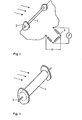
- the device in Figure 1 consists of a stretch wire 1 as a fault body, which is clamped on both sides in a holder 2. By wiring into a measuring bridge 3, the wire deformation is converted into an electrical signal.
- the deformation of the disturbance body 1 is detected with a single transducer 4.
- these can be made hollow to improve the bending behavior and / or with a flexible material, e.g. Plastic, coated.
- two transducers 5 and 6 can be introduced into a hollow or solid disturbance body 1, which are oriented in such a way that one 5 the deformation by the resistance and the other 6 only the deformation by the Buoyancy forces recorded.
- the disturbance body can be designed in two parts in order to improve the bending properties with regard to the effect of resistance and buoyancy.
- the parts 7 and 8, which are perpendicular to each other, are installed th transducers 5 and 6 are attached to each other at the ends. A distance remains between the two parts to allow the front part to bend due to the resistance.
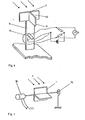
- the vortex frequency and thus the flow velocity can be measured contactlessly downstream from the disturbance body 1 by means of an ultrasonic measuring section consisting of transmitter 9 and receiver 10, as can be seen from FIG.
- the transmitter and receiver are preferably attached and adapted to the outer wall of the duct.
- a fault body 1 is supported by an elastic bearing 11, e.g. a spring element, kept in the flow.
- the disturbance body 1 has a plate 12 which is transverse to the direction of flow.
- a further plate 13 parallel to the direction of flow is provided on the rear.
- Strain gauges 14, which are attached crosswise on the front and rear of the bearing 11, serve as measuring sensors. The output signal obtained is evaluated as in the devices described above.
- a fault body 1 which has a T-shaped extension on the back. It can perform torsional vibrations about an axis that is transverse to the direction of flow. A restoring force is brought into the rest position by a torsion spring 15.
- a rotary potentiometer 16 serves as a measuring sensor. In this case, the amplitude and the frequency are evaluated from the signal obtained.
- the device shown in FIG. 8 essentially consists of a rigid disturbance body 1 with surfaces directed transversely and parallel to the direction of flow.
- two bores 17 and 18 are provided, one of which leads to the front surface and the other to a surface which is not in the dead water.
- a hot wire anemometer 22 is used for frequency measurement. The signals are evaluated in a corresponding electronics 23.
- the fault body can have different cross-sectional profiles.
- sharp edges 24 are attached to the back of the disturbance body for better detachment of the vertebrae.
- FIG. 9c A further improvement can be achieved with the embodiment shown in FIG. 9c, in which a surface 25 running parallel to the direction of flow and additionally at the end of this surface for better shaping of the vortices are attached to the rear of the fault body.
- Figure 9 may be present d obliquely to dirt particles or similar particles contained in the fluid dismissed at the front of body disturbance to the flow direction inclined surfaces 27 shown.
- the front of the fault body is well rounded off for the same purpose.
- the cross section of the flow channel can be changed to adapt the disturbance body to the flow conditions.
- this is achieved by attaching two flat, thin-walled guide surfaces 28, optionally held by supports, parallel to the flow and parallel and at the same distance from the disturbance body 1.
- the inlet edges should be well rounded and the lengths of the surfaces 28 in front of and behind the interference body 1 should be dimensioned such that the flow in the inner measuring channel formed through which only a partial mass flow of the fluid flows is hydrodynamic.
- the same effect is achieved by attaching a coaxial measuring channel 29 in the flow channel, only a partial mass flow of the fluid flowing through this measuring channel and the fault body 1 being used only in this measuring channel.
- the measuring channel wall should be thin and well rounded at the inlet.
- the length of the measuring channel should ensure a hydrodynamically designed flow in front of and behind the interference body.
- the measuring channel is held by supports 30 which are hollow and thus enable the electrical signal lines to be passed on from or to the measuring transducers through the measuring channel wall and through the outer channel wall.
Abstract
Description
Die Erfindung betrifft ein Verfahren zur dynamischen und dichteunabhängigen Bestimmung des Massenstromes von Fluiden sowie Vorrichtungen zur Durchführung dieses Verfahrens. Dabei werden an einem einzigen in die Strömung eingebrachten Störungskörper zur gleichen Zeit und am selben Ort Geschwindigkeit und Staudruck des Fluids erfaßt und zur Ergebnisgröße "Massenstrom" kombiniert.The invention relates to a method for the dynamic and density-independent determination of the mass flow of fluids and devices for carrying out this method. The speed and dynamic pressure of the fluid are recorded at a single fault body introduced into the flow at the same time and in the same place and combined to form the result variable "mass flow".
Die gebräuchlichsten Verfahren zur Bestimmung des Massenstroms basieren auf Messungen des Volumenstroms bzw. der Geschwindigkeit und der Dichte des Mediums und der nachfolgenden rechnerischen Kombination dieser beiden Meßgrößen. Dynamische Echtzeitmessungen der Dichte sind gewöhnlich nur in solchen Medien möglich, bei denen die chemische Zusammensetzung und die thermodynamischen Zustandsfunktionen bekannt sind. Dies ist bei vielen technischen Anwendungen jedoch nicht der Fall. Selbst wenn die Zusammensetzung und die Zustandsfunktionen bekannt sind, bedeutet die Dichtebestimmung einen hohen meßtechnischen Aufwand, dadurch daß Druck und Temperatur gemessen und daraus die Dichte berechnet werden müssen.The most common methods for determining the mass flow are based on measurements of the volume flow or the speed and density of the medium and the subsequent mathematical combination of these two measured variables. Dynamic real-time measurements of density are usually only possible in media where the chemical composition and the thermodynamic state functions are known. However, this is not the case for many technical applications. Even if the composition and the state functions are known, the determination of density means a high level of metrological effort, since pressure and temperature must be measured and the density calculated from this.
Zahlreiche Verfahren zur Messung des Volumenstroms bzw. der Geschwindigkeit besitzen bewegliche Teile, z.B. Flügelradanemometer, Drehkolbenzähler, und sind daher besonders empfindlich gegen Verschleiß und Verschmutzung. Auch Verfahren, welche Druckmessungen erfordern, z.B. Blendenmessungen, Staudruckmessungen, sind wegen der dabei vorhandenen Druckaufnahmebohrungen, -leitungen und -membranen häufig anfällig gegen Verschmutzungen des Mediums durch Feststoffpartikel o.ä., was zu erheblichen Meßfehlern bzw. zu verstärkt notwendigem Wartungsaufwand für die Meßeinrichtung führt. Außerdem verursachen viele der bekannten Verfahren einen hohen Druckverlust durch die Meßstelle selbst. Es sind bereits Strömungsmesser bekannt, die nach dem Prinzip der Karman'schen Wirbelstraße arbeiten (sog. Vortex Shedding Meter, z.B. US-PS 3 587 312, DE-OS 28 27 985, US-PS 3 972 232, DE-OS 24 08 246, DE-OS 20 37 198). Diese Verfahren und Vorrichtungen sind jedoch ausnahmslos nur zur Messung der Geschwindigkeit, nicht jedoch des Massenstroms geeignet.Numerous methods for measuring the volume flow or the speed have moving parts, e.g. Vane anemometer, rotary piston counter, and are therefore particularly sensitive to wear and contamination. Also procedures that require pressure measurements, e.g. Aperture measurements, dynamic pressure measurements, are often susceptible to contamination of the medium by solid particles or the like because of the pressure-receiving bores, lines and membranes present, which leads to considerable measurement errors or to an increasingly necessary maintenance effort for the measuring device. In addition, many of the known methods cause a high pressure loss through the measuring point itself. Flowmeters are already known which operate on the principle of Karman's vortex street (so-called vortex shedding meters, for example US Pat. No. 3,587,312, DE-OS 28 27 985, US Pat. No. 3,972,232, DE-OS 24 08 246, DE-OS 20 37 198). However, without exception, these methods and devices are only suitable for measuring the speed, but not the mass flow.
Es gibt auch Ansätze dafür, den Massenstrom über die Verwirbelung des Fluids durch Störkörper zu ermitteln (z.B. sog. Swirl Meter, US-PS 3 885 432, DE-AS 14 98 271), wobei durch Druckmessung an den Wirbeln selbst ein einziges Signal gewonnen wird, dessen Frequenz ein Maß für die Geschwindigkeit des Fluids und dessen Amplitude ein Maß für die kinetische Energie der Wirbel darstellt. Es besteht jedoch kein eindeutiger Zusammenhang,nach welchem von der kinetischen Energie der Wirbel auf die kinetische Energie des Fluids geschlossen werden kann, insbesondere wenn sich Verschmutzungen oder andersphasige Bestandteile im Fluid befinden. Außerdem müssen für eine genaue Messung die Wirbel sehr gut ausgebildet sein, was einen hohen Druckverlust bewirkt.There are also approaches for determining the mass flow via the swirling of the fluid through interfering bodies (eg so-called swirl meters, US Pat. No. 3,885,432, DE-AS 14 98 271), a single signal being obtained by measuring the pressure on the vertebrae themselves whose frequency is a measure of the speed of the fluid and whose amplitude is a measure of the kinetic energy of the vertebrae. However, there is no clear connection, according to which of the kinetic energy the vortex can be inferred about the kinetic energy of the fluid, especially if there are contaminants or components of different phases in the fluid. In addition, the vertebrae must be very well trained for an accurate measurement, which causes a high pressure loss.
Der vorliegenden Erfindung liegt daher die Aufgabe zugrunde, eine einfache Methode bzw. eine Meßeinrichtung zu schaffen, die es ermöglich, ohne Kenntnis der Dichte des Strömungsmediums dynamisch den Massenstrom zu bestimmen, d.h. auch unabhängig zu sein von Schwankungen der chemischen Zusammensetzung, der Dichte und der Geschwindigkeit des Fluids. Darüberhinaus soll die Vorrichtung möglichst keine beweglichen Teile besitzen, wenig anfällig sein gegenber Verschmutzung und keinen zu hohen Druckverlust an der Meßstelle bewirken.The present invention is therefore based on the object of providing a simple method or a measuring device which makes it possible to dynamically determine the mass flow without knowing the density of the flow medium, i.e. also to be independent of fluctuations in chemical composition, density and speed of the fluid. In addition, the device should have as few moving parts as possible, should be less susceptible to contamination and should not cause excessive pressure loss at the measuring point.
Es hat sich nun gezeigt, daß sich diese Aufgabe mit einem Verfahren gemäß Anspruch 1 lösen läßt, dadurch, daß die kinetische Energie der Strömung bzw. der Staudruck direkt gemessen wird. Einige Ausführungsformen des erfindungsgemäßen Verfahrens sind in den Ansprüchen 2 bis 9 erläutert, während Ansprüche 10 bis 21 Vorrichtungen zur Bestimmung des Massenflusses betreffen.It has now been shown that this object can be achieved with a method according to
Zur Lösung dieser Aufgabe der dichteunabhängigen Massenstrombestimmung lassen sich erfindungsgemäß an einem einzigen in die Strömung eingebrachten Störungskörper die Geschwindigkeit v und der Staudruck (ig v2) messen und zum Massenstrom m nach der Beziehung
Der quer zur Strömung eingesetzte Störungskörper dient einerseits dazu, an seiner Rückseite eine periodische Ablösung von Wirbeln zu erzeugen. Für die Frequenz f dieser ablösenden Wirbel gilt die Beziehung![]()
![]()
Andererseits stellt der Störungskörper der Strömung einen mechanischen Widerstand entgegen. Die von der Strömung auf einen elastisch verformbaren oder elastisch gelagerten Körper ausgeübte Kraft ist meßbar durch die am Körper oder an der Lagerung auftretende elastische Verformung entsprechend einer bekannten Federkennlinie. Zwischen dieser Strömungskraft Fw und dem Staudruck der Strömung (½S v2) besteht die Beziehung![]()
![]()
Es ist auch möglich, den Staudruck unmittelbar an einem starren Körper zu ermitteln durch Anbringen einer Druckbohrung gegen die Strömungsrichtung, wobei der Gesamtdruck der Strömung gemessen wird. Durch Differenzschaltung mit einer Druckmeßbohrung, an welcher der statische Druck der Strömung gemessen wird, erhält man den dynamischen Druck.It is also possible to determine the dynamic pressure directly on a rigid body by making a pressure hole against the flow direction, the total pressure of the flow being measured. The differential pressure with a pressure measuring hole, at which the static pressure of the flow is measured, gives the dynamic pressure.
Erfindungsgemäß ist die Messung der Fluiddichte für die Bestimmung des Massenstroms nicht erforderlich. Dennoch ist es möglich, neben der Geschwindigkeit v, welche unmittelbar als Ergebnis der Wirbelfrequenzmessung auftritt, aus der Beziehung
Das Meßverfahren beruht auf dem Prinzip, daß ein einziger Störungskörper in die Strömung eingebracht wird und daß sowohl die Frequenz der durch diesen Körper verursachten ablösenden Wirbel als auch die an diesem Körper wirkende Strömungskraft als Meßgrößen gewonnen werden.The measuring method is based on the principle that a single disturbance body is introduced into the flow and that both the frequency of the detaching vortices caused by this body and the flow force acting on this body are obtained as measured variables.
Die Aufnahme der Frequenz der ablösenden Wirbel kann am Störungskörper selbst erfolgen, da die abwechselnde Wirbelablösung auf beiden Seiten der Umströmung ein entsprechendes periodisches Druckgefälle am Körper quer zu Strömungsrichtung hervorruft und den Störungskörper zu Schwingungen quer zur Strömungsrichtung mit der Wirbelfrequenz anregt. Dieses Verhalten kann auch mit Hilfe der Auftriebskraft FA am Körper und einem periodisch mit der Zeit variablen Auftriebsbeiwert cx(t) beschrieben werden mit der Beziehung
Für den Fall, daß das Querschnittsprofil des Strömungskörpers in Richtung der Auftriebskraft nicht symmetrisch ist, treten zusätzlich zur Biegung auch Torsions- bzw. Deviationsphänomene auf. Auch diese Weg- und Winkeländerungen können als Meßgröße erfaßt werden, um die Auftriebskraft zu bestimmen.In the event that the cross-sectional profile of the flow body is not symmetrical in the direction of the lifting force, torsion or deviation phenomena also occur in addition to the bend. These path and angle changes can also be recorded as a measurement variable in order to determine the buoyancy force.
Speziell an einem starren, drehbar gelagerten Störungskörper kann die Drehbewegung gemessen werden, wobei der sich zeitlich ändernde Drehwinkel proportional der Auftriebskraft ist und somit auch dem Produkt cA(t). ![]()
![]()
Eine andere Möglichkeit der Wirbelfrequenzmessung ist gegeben durch das Anbringen von je einem Ultraschallsender und -empfänger an zwei gegenüberliegenden, zum Störungskörper parallelen Grenzflächen der Strömung in einer in Strömungsrichtung hinter dem Störungskörper liegenden Position, an der die Wirbel eine besonders gute Ausbildung besitzen. Beim Durchströmen eines Wirbels durch die Ultraschallstrecke moduliert der Wirbel als Dichteschwankung das akustische Signal. Die Frequenz der auftretenden Modulationen ist dabei gleich der Wirbelfrequenz.Another possibility of the vortex frequency measurement is given by attaching an ultrasonic transmitter and receiver to two opposite boundary surfaces of the flow parallel to the disturbance body in a position behind the disturbance body in the direction of flow, at which the vortexes have a particularly good design. When a vortex flows through the ultrasound path, the vortex modulates the acoustic signal as a density fluctuation. Odulationen the frequency of M occurring is equal to the vortex frequency.
Die Strömungskraft kann indirekt über die elastische Verformung bzw. Durchbiegung des Störungskörpers oder dessen Lagerung in Strömungsrichtung mit Hilfe von Dehnungsmeßstreifen, piezoresistiven Aufnehmern oder anderen Wegaufnehmern erfaßt werden. Hierzu muß die Federkennlinie des Körpers und die Lastverteilung, d.h. das Strömungsprofil, bekannt sein. Mittels des Widerstandsbeiwertes c läßt sich dann mit Gleichung III der dynamische Druck bzw. Staudruck berechnen.The flow force can be detected indirectly via the elastic deformation or deflection of the fault body or its storage in the flow direction with the aid of strain gauges, piezoresistive transducers or other displacement transducers. For this, the spring characteristic of the body and the load distribution, i.e. the flow profile to be known. The dynamic pressure or dynamic pressure can then be calculated using equation III using the drag coefficient c.
Die Durchbiegung des Störungskörpers sowohl in Strömungsrichtung als auch senkrecht dazu können auch kombiniert in einem einzigen Signal erfaßt werden. Hierbei wird die gesamte elastische Verformung aufgrund der aus Widerstands- und Auftriebskraft resultierenden Gesamtkraft
Erfindungsgemäß muß der Störungskörper für verschiedene Strömungsgeschwindigkeitsbereiche und Fluide entsprechend dimensioniert und profiliert werden, damit sowohl die Wirbelablösung als auch die Widerstandskraft des Körpers gegen die Strömung in besonders meßgünstige Wertebereiche fallen, in denen begrenzte Änderungen oder Schwankungen der Fluideigenschaften wie Dichte, Zähigkeit, chemische Zusammensetzung und Geschwindigkeit, zu keinen nennenswerten Meßfehlern führen.According to the invention, the disturbance body must be dimensioned and profiled accordingly for different flow velocity ranges and fluids, so that both the vortex shedding and the body's resistance to the flow fall into particularly measurable value ranges, in which limited changes or fluctuations in the fluid properties such as density, viscosity, chemical composition and Speed, do not lead to any significant measuring errors.
Als Störungskörper eignen sich in besonderem Maße glatte Stäbe, deren Querschnittsprofil in Strömungsrichtung symmetrisch ist. Um eine gute und definierte Ablösestelle für die Wirbel zu erreichen, können an der Rückseite des Profils scharfe Kanten vorgesehen werden. Weiterhin können zur Verstärkung der durch die Wirbelablösung senkrecht zur Strömungsrichtung auftretenden oszillierenden Druckdifferenz an der Rückseite des Profils eine oder mehrere zur Strömungsrichtung parallele Flächen angebracht werden. Zur Abweisung und zum Schutz vor Ablagerungen von Schmutzpartikeln, Feststoffteilchen, Flüssigkeitstropfen, usw., die sich im Fluid befinden können, besteht die Möglichkeit, auch die Vorderseite des Profils entsprechend zu gestalten.Smooth rods whose cross-sectional profile is symmetrical in the direction of flow are particularly suitable as interference bodies. In order to achieve a good and defined detachment point for the vertebrae, sharp edges can be provided on the back of the profile. Furthermore, one or more surfaces parallel to the direction of flow can be attached to reinforce the oscillating pressure difference occurring due to the vortex shedding perpendicular to the direction of flow. To reject and protect against deposits of dirt particles, solid particles, liquid drops, etc., which may be in the fluid, it is also possible to design the front of the profile accordingly.
In solchen Fällen, in denen die Biegeverformungen des Störungskörpers sowohl in Strömungsrichtung als auch senkrecht dazu zur Messung herangezogen werden sollen, ist es auch möglich, die Biegeeigenschaften des Störungskörpers dadurch zu optimieren, daß der Störungskörper in zwei Teile längs seiner Achse aufgespalten wird, wobei jeder Teil für sich jeweils in einer der Richtungen das günstigste Flächenträgheitsmoment besitzt. Beide Teile sind an den Enden fest zusammengefügt und stellen insgesamt einen einzigen Störungskörper dar. Der axiale Abstand beider Teile wird bestimmt durch die maximale Durchbiegung des vorderen Teils in Strömungsrichtung.In such cases, in which the bending deformations of the disturbing body are to be used for measurement both in the direction of flow and perpendicular to it, it is also possible to optimize the bending properties of the disturbing body in that the disturbing body in two parts along its Axis is split, with each part having the most favorable area moment of inertia in each of the directions. Both parts are firmly joined at the ends and represent a single fault body. The axial distance between the two parts is determined by the maximum deflection of the front part in the direction of flow.
Da in geführten Strömungskanälen, z.B. einem Rohr, die Strouhalzahl Str und der Widerstandsbeiwert c von der Kontraktions- ziffer, d.h. vom Verhältnis der Strömungsfläche des Störungskörpers zur Kanalquerschnittsfläche abhängen können, kann in günstigen Fällen,(z.B. bei großen Kanaldurchmessern und schlanken Störungskörpern) eine künstliche Kontraktion hervorgerufen werden. Dies ist insbesondere möglich durch Einsetzen von zwei parallel zur Strömungsrichtung und zum Störungskörper verlaufende Leitflächen in einem zu bestimmenden Abstand vom Störungskörper. Diese Leitflächen können auch parallel zur Kanalwandung gekrümmt ausgeführt werden, so daß ein koaxialer innerer Kanal entsteht, in welchem die eigentliche Messung vorgenommen wird, wobei nur ein bestimmter Teil des Gesamtmassenstromes durch den inneren Kanal fließt. Der innere Kanal wird auf Stützen im eigentlichen größeren Kanal gehalten, wobei die Stützen hohl sind und die Fortleitung der elektrischen Meßsignalleitungen ermöglichen. Die Ausdehnung der Leitflächen in Strömungsrichtung vor und hinter dem Störungskörper sowie die Dicke der Leitflächen muß so bemessen sein, daß die Strömung im inneren Kanal sich hydrodynamisch voll ausbilden kann. Vorzugsweise soll die Einlaufkante der Leitflächen gut abgerundet sein.Since in guided flow channels, e.g. a pipe, the Strouhal number Str and the drag coefficient c can depend on the contraction number, i.e. on the ratio of the flow area of the fault body to the cross-sectional area of the duct, in favorable cases (e.g. with large duct diameters and slim fault bodies) an artificial one Contraction. This is possible in particular by inserting two guide surfaces running parallel to the direction of flow and to the fault body at a distance to be determined from the fault body. These guide surfaces can also be curved parallel to the channel wall, so that a coaxial inner channel is formed, in which the actual measurement is carried out, only a certain part of the total mass flow flowing through the inner channel. The inner channel is held on supports in the proper larger channel, wherein the supports are hollow and allow the propagation of the electrical eßsignalleitungen M. The extension of the guide surfaces in the direction of flow in front of and behind the fault body and the thickness of the guide surfaces must be dimensioned such that the flow in the inner channel can develop fully hydrodynamically. Preferably, the leading edge of the guide surfaces should be well rounded.
Gegenüber den bekannten Verfahren zur Ermittlung des Massenstroms bietet das erfindungsgemäße Verfahren den Vorteil, daß ohne Kenntnis der Dichte des Strömungsmediums der Massenstrom dynamisch gemessen werden kann, indem nur ein einziger Störungskörper in die Strömung eingebracht wird. Das Querschnittsprofil des Störungskörpers kann derart ausgelegt werden, daß die Messung in bestimmten Grenzen unabhängig von Schwankungen der chemischen Zusammensetzung, der Dichte, der Viskosität und der Geschwindigkeit des Fluids ist. Darüberhinaus ist das Verfahren wenig anfällig gegen Verschmutzungen des Fluids und insgesamt wartungsarm, da auch keine beweglichen Teile vorhanden sind. Durch entsprechende Auslegung kann der Druckverlust an der Meßstelle gering gehalten werden. Bei der direkten Messung der Strömungskraft wird auch der Massenanteil von Verschmutzungen oder andersphasigen Bestandteilen im Fluid im Gesamtmassenstrom mitberücksichtigt.Compared to the known methods for determining the mass flow, the method according to the invention has the advantage that the mass flow can be measured dynamically without knowing the density of the flow medium, in that only a single disturbance body is introduced into the flow. The cross-sectional profile of the disturbance body can be designed such that the measurement within certain limits is independent of fluctuations in the chemical composition, the density, the viscosity and the speed of the fluid. In addition, the process is not very susceptible to contamination of the fluid and is generally low-maintenance since there are no moving parts. The pressure loss at the measuring point can be kept low by appropriate design. The direct measurement of the flow force also takes into account the mass fraction of dirt or other phase components in the fluid in the total mass flow.
Im folgenden wird die Erfindung anhand von Zeichnungen näher erläutert. Es zeigen in schematischer Vereinfachung
Figur 1 eine mögliche Ausführungsform der Erfindung, bei welcher ein elastischer Störungskörper gleichzeitig als Meßwertaufnehmer für die Verformung aufgrund der Widerstands- und der Auftriebskräfte dient;Figur 2 eine mögliche Ausführungsform der Erfindung, bei welcher ein einziger Dehndraht oder ein anderer einzelner Meßwertaufnehmer im Störungskörper eingesetzt ist, der sowohl die Verformung aufgrund der Widerstands- als auch der Auftriebskraft erfaßt;Figur 3 eine mögliche Ausführungsform der Erfindung, bei welcher zwei Meßwertaufnehmer im Störungskörper eingesetzt sind, wobei einer nur die Verformung aufgrund der Widerstandkraft, der andere nur die Verformung aufgrund der Auftriebskraft erfaßt;- Figur 4 eine mögliche Ausführungsform der Erfindung, bei welcher der Störungskörper zweigeteilt ist und jedes Teil einen Meßwertaufnehmer enthält, welcher die der Hauptachse seines Flächenträgheitsmoments entsprechende überwiegende Verformung aufgrund der Widerstands- oder der Auftriebskraft erfaßt;
- Figur 5 eine erfindungsgemäße Vorrichtung, bei der zusätzlich zum Störungskörper eine Ultraschallmeßstrecke vorgesehen ist;
Figur 6 eine erfindungsgemäße Ausführungsform, bei der ein starrer Störungskörper elastisch gelagert ist;- Figur 7 eine Vorrichtung, die einen drehbar gelagerten, starren Störungskörper enthält;
Figur 8 eine Vorrichtung,bestehend aus einem starren mit Bohrungen versehenen Störungskörper, die unbeweglich in der Strömung anzubringen ist;- Figur 9a mögliche Ausführungsformen des
Störungskörpers bis 9e und - Figur 10a bis 10b Möglichkeiten zur Veränderung des Kontraktions- verhältnisses im Strömungskanal.
- Figure 1 shows a possible embodiment of the invention, in which an elastic disturbance body serves simultaneously as a transducer for the deformation due to the resistance and buoyancy forces;
- FIG. 2 shows a possible embodiment of the invention, in which a single extension wire or another individual measurement sensor is used in the fault body, which detects the deformation due to the resistance as well as the buoyancy force;
- Figure 3 shows a possible embodiment of the invention, in which two transducers are used in the fault body, one only detecting the deformation due to the resistance, the other only the deformation due to the buoyancy;
- FIG. 4 shows a possible embodiment of the invention, in which the disturbance body is divided into two and each part contains a transducer which detects the predominant deformation due to the resistance or buoyancy force corresponding to the main axis of its surface moment of inertia;
- Figure 5 shows a device according to the invention, in which an ultrasonic measuring section is provided in addition to the disturbance body;
- FIG. 6 shows an embodiment according to the invention, in which a rigid interference body is elastically supported;
- FIG. 7 shows a device which contains a rotatably mounted, rigid interference body;
- FIG. 8 shows a device consisting of a rigid disturbance body provided with bores, which is to be attached immovably in the flow;
- Figure 9a possible embodiments of the fault body to 9 e and
- 10a to 10b possibilities for changing the contraction ratio in the flow channel.
Wird ein Störungskörper in die Strömung gebracht, so lösen sich periodisch Wirbel ab. Aus den auf den Störungskörper wirkenden Strömungskräften, d.h. der Widerstandskraft F w und den periodischen Auftriebskräften FA, wobei Fw senkrecht zu FA ist, resultiert eine Verformung eines elastischen Stö- rungskörpers oder seiner elastischen Lagerung. Hier wird anstelle von Widerstandskörper der Ausdruck Störungskörper gewählt, weil der Körper außer zur reinen Aufnahme der Widerstandskraft zur Erzeugung von Wirbeln dienen sollIf a disturbance body is brought into the flow, eddies periodically become detached. From the disturbance acting on the body flow forces, ie the resistance force F w and the periodic lifting forces F A, where F w F perpendicular to A, resulting in a deformation of an elastic body or S TOE approximately its elastic storage. Here the expression disturbance body is chosen instead of the resistance body because the body is supposed to serve for the creation of eddies in addition to the pure absorption of the resistance
Die Vorrichtung in Figur 1 besteht aus einem Dehndraht 1 als Störungskörper, der in einem Halter 2 beidseitig eingespannt ist. Durch Verschaltung in eine Meßbrücke 3 wird die Drahtverformung in ein elektrisches Signal umgewandelt.The device in Figure 1 consists of a
Nach der in Figur 2 gezeigten Ausführungsform wird mit einem einzigen Meßwertaufnehmer 4 die Verformung des Störungskörpers 1 erfaßt. Bei allen erfindungsgemäß eingesetzten Störungskörpern können diese zur Verbesserung des Biegeverhaltens hohl ausgeführt und/oder mit einem biegeelastischen Material, z.B. Kunststoff, beschichtet sein.According to the embodiment shown in Figure 2, the deformation of the
Zur Gewinnung von zwei Signalen können bei einer in Figur 3 gezeigten Ausführungsform in einen hohlen oder massiven Störungskörper 1 zwei Meßwertaufnehmer 5 und 6 eingebracht werden, die so ausgerichtet sind, daß einer 5 die Verformung durch die Widerstandskraft und der andere 6 nur die Verformung durch die Auftriebskräfte erfaßt.In order to obtain two signals, in one embodiment shown in FIG. 3, two
Gemäß Figur 4 kann der Störungskörper zur Verbesserung der Biegeeigenschaften hinsichtlich der Wirkung von Widerstandskraft und Auftriebskraft zweigeteilt ausgeführt sein. Die zueinander senkreicht stehenden Teile 7 und 8 mit eingebauten Meßwertaufnehmern 5 und 6 werden an den Enden miteinander befestigt. Zwischen beiden Teilen verbleibt ein Abstand, um die Durchbiegung des vorderen Teils aufgrund der Widerstandskraft zu ermöglichen.According to FIG. 4, the disturbance body can be designed in two parts in order to improve the bending properties with regard to the effect of resistance and buoyancy. The
Die Wirbelfrequenz und somit die Strömungsgeschwindigkeit kann berührungslos stromab vom Störungskörper 1 mittels einer aus Sender 9 und Empfänger 10 bestehenden Ultraschallmeßstrecke gemessen werden, wie es aus Figur 5 hervorgeht. Sender und Empfänger werden vorzugsweise an der Kanalaußenwand angebracht und angepaßt.The vortex frequency and thus the flow velocity can be measured contactlessly downstream from the
Gemäß einer in Figur 6 dargestellten Ausführungsform der erfindungsgemäßen Vorrichtung wird ein Störungskörper 1 durch eine elastische Lagerung 11, z.B. ein Federelement, in der Strömung gehalten. Der Störungskörper 1 weist eine quer zur Strömungsrichtung stehende Platte 12 auf. Auf der Rückseite ist eine weitere parallel zur Strömungsrichtung stehende Platte 13 vorgesehen. Diese T-förmige Verlängerung des Störungskörpers verstärkt das Torsionsmoment. Als Meßwertaufnehmer dienen Dehnungsmeßstreifen 14, die kreuzweise auf der Vorder- und Rückseite der Lagerung 11 angebracht sind. Das gewonnene Ausgangssignal wird wie bei den oben beschriebenen Vorrichtungen ausgewertet.According to an embodiment of the device according to the invention shown in FIG. 6, a
Aus Figur 7 geht hervor, daß ebenfalls ein Störungskörper 1 verwendet wird, der auf der Rückseite eine T-förmige Verlängerung aufweist. Er kann um eine quer zur Strömungsrichtung stehende Achse Drehschwingungen ausführen. Durch eine Drehfeder 15 wird eine Rückstellkraft in die Ruhelage bewirkt. Ein Drehpotentiometer 16 dient hierbei als Meßwertaufnehmer. Aus dem gewonnenen Signal werden in diesem Fall die Amplitude und die Frequenz ausgewertet.From Figure 7 it can be seen that a
Die in Figur 8 dargestellte Vorrichtung besteht im wesentlichen aus einem starren Störungskörper 1 mit quer und parallel zur Strömungsrichtung gerichteten Flächen. Zur Bestimmung des Staudrucks sind zwei Bohrungen 17 und 18 vorgesehen, von denen eine zur Vorderfläche und die andere zu einer Fläche führt, die nicht im Totwasser liegt. Zwei weitere Öffnungen 19 und 20, die miteinander durch einen Kanal 21 verbunden sind, enden im Totwasserbereich auf zwei Seitenflächen, die sich gegenüberstehen. Zur Frequenzmessung wird ein Heißdrahtanemometer 22 verwendet. Die Signale werden in einer entsprechenden Elektronik 23 ausgewertet.The device shown in FIG. 8 essentially consists of a
Der Störungskörper kann verschiedene Querschnittsprofile besitzen. In Figur 9a werden an der Rückseite des Störungskörpers scharfe Kanten 24 zur besseren Ablösung der Wirbel angebracht.The fault body can have different cross-sectional profiles. In Figure 9a,
Gemäß Figur 9b kann an der Rückseite des Störungskörpers eine parallel zur Strömungsrichtung verlaufende Fläche 25 zur Ver- stärkung der Auftriebskräfte vorgesehen sein.According to figure 9b extending parallel to the direction of
Eine weitere Verbesserung kann mit der in Figur 9c gezeigten Ausführungsform erzielt werden, bei der an der Rückseite des Störungskörpers eine parallel zur Strömungsrichtung verlaufende Fläche 25 und zusätzlich am Ende dieser Fläche zur besseren Formung der Wirbel ausgebildete Leitflügel 26 angebracht sind.A further improvement can be achieved with the embodiment shown in FIG. 9c, in which a
Ferner können gemäß Figur 9d an der Vorderseite des Störungskörpers schräg zur Strömungsrichtung geneigte Flächen 27 vorhanden sein, um Schmutzteilchen oder ähnliche im Fluid befindliche Partikel abzuweisen.Furthermore, Figure 9 may be present d obliquely to dirt particles or similar particles contained in the fluid dismissed at the front of body disturbance to the flow direction inclined surfaces 27 shown.
Nach der in Figur 9e gezeigten Ausführung wird zum selben Zweck die Vorderseite des Störungskörpers gut abgerundet.According to the embodiment shown in FIG. 9e, the front of the fault body is well rounded off for the same purpose.
Zur Anpassung des Störungskörpers an die Strömungsverhältnisse kann der Querschnitt des Strömungskanals verändert werden. In Figur 10 a wird dies durch Anbringung von zwei ebenen, dünnwandigen und gegebenenfalls durch Stützen gehaltenen Leitflächen 28 parallel zur Strömung und parallel und in gleichem Abstand zum Störungskörper 1 erzielt. Dabei sollten die Einlaufkanten gut gerundet und die Längen der Flächen 28 vor und hinter dem Störungskörper 1 so bemessen sein, daß die Strömung im so gebildeten inneren Meßkanal, durch welchen nur ein Teilmassenstrom des Fluids strömt, hydrodynamisch ausgebildet ist.The cross section of the flow channel can be changed to adapt the disturbance body to the flow conditions. In FIG. 10 a, this is achieved by attaching two flat, thin-walled guide surfaces 28, optionally held by supports, parallel to the flow and parallel and at the same distance from the
Gemäß Figur 10b wird derselbe Effekt durch Anbringung eines koaxialen Meßkanals 29 im Strömungskanal erreicht, wobei durch diesen Meßkanal nur ein Teilmassenstrom des Fluids strömt und der Störungskörper 1 nur in diesem Meßkanal eingesetzt wird. Die Meßkanalwand sollte dünn und am Einlauf gut gerundet sein. Die Länge des Meßkanals sollte vor und hinter dem Störungskörper eine hydrodynamisch ausgebildete Strömung gewährleisten. Der Meßkanal wird von Stützen 30 gehalten, welche hohl ausgeführt sind und somit die Fortleitung der elektrischen Signalleitungen von dem oder von den Meßwertaufnehmern durch die Meßkanalwand und durch die äußere Kanalwand ermöglichen.According to FIG. 10b, the same effect is achieved by attaching a
Claims (21)

Priority Applications (1)
| Application Number | Priority Date | Filing Date | Title |
|---|---|---|---|
| AT81106568T ATE17606T1 (en) | 1980-08-29 | 1981-08-25 | METHOD AND DEVICE FOR DYNAMIC AND DENSITY-INDEPENDENT DETERMINATION OF MASS FLOW. |
Applications Claiming Priority (2)
| Application Number | Priority Date | Filing Date | Title |
|---|---|---|---|
| DE3032578A DE3032578C2 (en) | 1980-08-29 | 1980-08-29 | Method and device for dynamic and density-independent determination of the mass flow |
| DE3032578 | 1980-08-29 |
Publications (2)
| Publication Number | Publication Date |
|---|---|
| EP0046965A1 true EP0046965A1 (en) | 1982-03-10 |
| EP0046965B1 EP0046965B1 (en) | 1986-01-22 |
Family
ID=6110679
Family Applications (1)
| Application Number | Title | Priority Date | Filing Date |
|---|---|---|---|
| EP81106568A Expired EP0046965B1 (en) | 1980-08-29 | 1981-08-25 | Method and device for determining mass flow dynamically and independent of fluid density |
Country Status (4)
| Country | Link |
|---|---|
| US (1) | US4448081A (en) |
| EP (1) | EP0046965B1 (en) |
| AT (1) | ATE17606T1 (en) |
| DE (2) | DE3032578C2 (en) |
Cited By (5)
| Publication number | Priority date | Publication date | Assignee | Title |
|---|---|---|---|---|
| WO1985000883A1 (en) * | 1983-08-04 | 1985-02-28 | The Foxboro Company | Planar-measuring vortex-shedding mass flowmeter |
| DE19740708A1 (en) * | 1997-09-16 | 1999-03-25 | Kem Kueppers Elektromech Gmbh | Measurement value transmitter for vortex flowmeter |
| DE19740707A1 (en) * | 1997-09-16 | 1999-03-25 | Kem Kueppers Elektromech Gmbh | Measurement value transmitter for vortex flowmeter |
| DE10227726A1 (en) * | 2002-06-21 | 2004-01-15 | Invensys Metering Systems Ag | Vortex flowmeter |
| WO2006122694A2 (en) * | 2005-05-19 | 2006-11-23 | Technische Universität Darmstadt | Method for monitoring a fluid flow measurement and sensor system for measuring the flow of fluid |
Families Citing this family (35)
| Publication number | Priority date | Publication date | Assignee | Title |
|---|---|---|---|---|
| EP0110321B1 (en) * | 1982-11-25 | 1988-09-07 | Oval Engineering Co., Ltd. | Vortex flow meter |
| JPS6162820A (en) * | 1984-09-04 | 1986-03-31 | Toyota Motor Corp | Sucked air mass flow amount detection apparatus using karman voltex air flow sensor |
| DE3775507D1 (en) * | 1986-09-30 | 1992-02-06 | Siemens Ag | FLOW FLOW METER ACCORDING TO THE SWIRL FLOW METER PRINCIPLE, IN PARTICULAR AIR FLOW METER FOR ELECTRICAL INJECTION CONTROLS IN CAR ENGINES. |
| US4779458A (en) * | 1986-12-29 | 1988-10-25 | Mawardi Osman K | Flow sensor |
| US4864868A (en) * | 1987-12-04 | 1989-09-12 | Schlumberger Industries, Inc. | Vortex flowmeter transducer |
| DE3800219A1 (en) * | 1988-01-07 | 1989-07-20 | Helmut Dipl Ing Roppelt | Method and measuring device for determining the volume of exhaust-gas flows, in particular for determining automobile exhaust-gas volumes |
| DE3916056A1 (en) * | 1989-05-17 | 1990-11-22 | Kuipers Ulrich | Measuring mass and/or vol. throughflow and/or density and/or viscosity - using sensor and choke and/or baffle element to detect differential pressure of fluid |
| US5060522A (en) * | 1990-01-19 | 1991-10-29 | Lew Hyok S | Mass-volume vortex flowmeter |
| US5152181A (en) * | 1990-01-19 | 1992-10-06 | Lew Hyok S | Mass-volume vortex flowmeter |
| US5372046A (en) * | 1992-09-30 | 1994-12-13 | Rosemount Inc. | Vortex flowmeter electronics |
| US5351559A (en) * | 1993-08-31 | 1994-10-04 | National Science Council | T-shape vortex shedder wherein the bluff body extends across the diameter of a circular pipe and has a length to width ratio between 1.56 and 2.0 |
| US5447073A (en) * | 1994-02-04 | 1995-09-05 | The Foxboro Company | Multimeasurement replaceable vortex sensor |
| US5463904A (en) * | 1994-02-04 | 1995-11-07 | The Foxboro Company | Multimeasurement vortex sensor for a vortex-generating plate |
| DE19619632A1 (en) * | 1996-05-15 | 1997-11-20 | S K I Schlegel & Kremer Indust | Measuring density of flowing fluid using at least two measuring points |
| US5880377A (en) * | 1996-10-15 | 1999-03-09 | Lsi Logic Corporation | Method for low velocity measurement of fluid flow |
| US5804740A (en) * | 1997-01-17 | 1998-09-08 | The Foxboro Company | Capacitive vortex mass flow sensor |
| US6170338B1 (en) | 1997-03-27 | 2001-01-09 | Rosemont Inc. | Vortex flowmeter with signal processing |
| US6267013B1 (en) | 1998-11-18 | 2001-07-31 | Stephen T. Stark | Flow anomaly detector |
| US6865957B1 (en) * | 2002-04-17 | 2005-03-15 | Nathaniel Hughes | Adaptable fluid mass flow meter device |
| DE10240189A1 (en) * | 2002-08-28 | 2004-03-04 | Endress + Hauser Flowtec Ag, Reinach | Mass flow measuring method for fluid in pipe, by setting up Karman vortices and determining pressure value representing time-averaged mean dynamic pressure, and flow value |
| US7212928B2 (en) * | 2002-09-06 | 2007-05-01 | Invensys Systems, Inc. | Multi-measurement vortex flow meter |
| JP5096915B2 (en) | 2004-03-25 | 2012-12-12 | ローズマウント インコーポレイテッド | Simplified fluid property measurement method |
| EP1936332A1 (en) | 2006-12-22 | 2008-06-25 | Nederlandse Organisatie voor Toegepast-Natuuurwetenschappelijk Onderzoek TNO | Karman vortex flowmeter assembly comprising a fiber Bragg grating sensor and method to measure a fluid flow rate |
| WO2009109056A1 (en) * | 2008-03-07 | 2009-09-11 | Belimo Holding Ag | Device for measuring and regulating a volume flow in a ventilation pipe |
| US9250108B2 (en) * | 2013-09-27 | 2016-02-02 | Rosemount Inc. | Differential pressure based flow measurement device having improved pitot tube configuration |
| DE102013019872B4 (en) * | 2013-11-28 | 2023-03-30 | Universität des Saarlandes Campus Saarbrücken | Method and device for determining the viscosity of a liquid flowing in a flow channel |
| DE102015000629A1 (en) * | 2015-01-22 | 2016-07-28 | Viessmann Werke Gmbh & Co Kg | Turbo compressor |
| US10539443B2 (en) | 2015-12-28 | 2020-01-21 | The Trustees Of Princeton University | Elastic filament velocity sensor |
| EP3546954B1 (en) * | 2016-01-07 | 2022-12-14 | Analog Devices, Inc. | 3-axis angular accelerometer |
| CN108351238A (en) * | 2016-07-21 | 2018-07-31 | 罗斯蒙特公司 | The vortex shedding flowmeter of process intrusion with reduction |
| WO2018106758A1 (en) | 2016-12-06 | 2018-06-14 | Ysi, Inc. | Method for compensating for venturi effects on pressure sensors in moving water |
| US11351313B2 (en) | 2017-02-23 | 2022-06-07 | The Trustees Of Princeton University | System and method for monitoring injection site pressure |
| WO2020046157A1 (en) * | 2018-08-30 | 2020-03-05 | Micro Motion Inc. | Non-invasive sensor for vortex flowmeter |
| JP7241885B2 (en) | 2018-12-24 | 2023-03-17 | マイクロ モーション インコーポレイテッド | Vortex flowmeter and flow measurement method |
| CN110206688B (en) * | 2019-06-13 | 2020-09-29 | 石家庄铁道大学 | Power generation device |
Citations (6)
| Publication number | Priority date | Publication date | Assignee | Title |
|---|---|---|---|---|
| US3719073A (en) * | 1970-09-14 | 1973-03-06 | American Standard Inc | Mass flow meter |
| FR2173962A1 (en) * | 1972-01-17 | 1973-10-12 | Omf California Inc | |
| US3878716A (en) * | 1973-12-19 | 1975-04-22 | Hokushin Electric Works | Karman vortex shedder |
| US3996796A (en) * | 1975-03-10 | 1976-12-14 | Corning Glass Works | Flow meter |
| US4112879A (en) * | 1975-02-24 | 1978-09-12 | Robert Bosch Gmbh | Process for the regulation of the optimum operational behavior of an internal combustion engine |
| US4196621A (en) * | 1975-11-20 | 1980-04-08 | National Research Development Corporation | Devices for detecting fluid flow |
Family Cites Families (16)
| Publication number | Priority date | Publication date | Assignee | Title |
|---|---|---|---|---|
| BE394587A (en) * | 1932-02-25 | |||
| US3370463A (en) * | 1964-07-29 | 1968-02-27 | American Standard Inc | Mass flow meter |
| US3587312A (en) * | 1968-12-24 | 1971-06-28 | Eastech | Differential sensor bluff body flowmeter |
| US3927566A (en) * | 1971-06-17 | 1975-12-23 | Kent Instruments Ltd | Flowmeters |
| US3885432A (en) * | 1972-03-06 | 1975-05-27 | Fischer & Porter Co | Vortex-type mass flowmeters |
| US3888120A (en) * | 1973-04-26 | 1975-06-10 | Fischer & Porter Co | Vortex type flowmeter with strain gauge sensor |
| US3863501A (en) * | 1973-12-19 | 1975-02-04 | Honeywell Inc | Magnetostrictive sensor for a flowmeter |
| DE2408246C3 (en) * | 1974-02-21 | 1981-10-15 | Bopp & Reuther Gmbh, 6800 Mannheim | Flow meter |
| US3972232A (en) * | 1974-04-24 | 1976-08-03 | The Foxboro Company | Vortex flow meter apparatus |
| US4010645A (en) * | 1976-03-19 | 1977-03-08 | Fischer & Porter Co. | Density-responsive mass flow vortex type meter |
| SE7713507L (en) * | 1976-12-02 | 1978-06-03 | Garrett Corp | SET AND DEVICE FOR DETERMINING A MASS FLOW |
| US4171643A (en) * | 1976-12-29 | 1979-10-23 | Rosemount Inc. | Vortex shedding flowmeter construction |
| DE2827985C2 (en) * | 1977-11-10 | 1984-03-08 | Yokogawa Hokushin Electric Corp., Musashino, Tokyo | Flow meter |
| US4281553A (en) * | 1978-05-04 | 1981-08-04 | Datta Barua Lohit | Vortex shedding flowmeter |
| JPS5576916A (en) * | 1978-12-06 | 1980-06-10 | Nissan Motor Co Ltd | Sucked air quantity detector |
| JPS5582018A (en) * | 1978-12-15 | 1980-06-20 | Nissan Motor Co Ltd | Karman vortex flowmeter |
-
1980
- 1980-08-29 DE DE3032578A patent/DE3032578C2/en not_active Expired
-
1981
- 1981-08-21 US US06/295,021 patent/US4448081A/en not_active Expired - Fee Related
- 1981-08-25 EP EP81106568A patent/EP0046965B1/en not_active Expired
- 1981-08-25 DE DE8181106568T patent/DE3173562D1/en not_active Expired
- 1981-08-25 AT AT81106568T patent/ATE17606T1/en not_active IP Right Cessation
Patent Citations (6)
| Publication number | Priority date | Publication date | Assignee | Title |
|---|---|---|---|---|
| US3719073A (en) * | 1970-09-14 | 1973-03-06 | American Standard Inc | Mass flow meter |
| FR2173962A1 (en) * | 1972-01-17 | 1973-10-12 | Omf California Inc | |
| US3878716A (en) * | 1973-12-19 | 1975-04-22 | Hokushin Electric Works | Karman vortex shedder |
| US4112879A (en) * | 1975-02-24 | 1978-09-12 | Robert Bosch Gmbh | Process for the regulation of the optimum operational behavior of an internal combustion engine |
| US3996796A (en) * | 1975-03-10 | 1976-12-14 | Corning Glass Works | Flow meter |
| US4196621A (en) * | 1975-11-20 | 1980-04-08 | National Research Development Corporation | Devices for detecting fluid flow |
Cited By (8)
| Publication number | Priority date | Publication date | Assignee | Title |
|---|---|---|---|---|
| WO1985000883A1 (en) * | 1983-08-04 | 1985-02-28 | The Foxboro Company | Planar-measuring vortex-shedding mass flowmeter |
| DE19740708A1 (en) * | 1997-09-16 | 1999-03-25 | Kem Kueppers Elektromech Gmbh | Measurement value transmitter for vortex flowmeter |
| DE19740707A1 (en) * | 1997-09-16 | 1999-03-25 | Kem Kueppers Elektromech Gmbh | Measurement value transmitter for vortex flowmeter |
| DE19740707C2 (en) * | 1997-09-16 | 1999-12-02 | Kem Kueppers Elektromech Gmbh | Transducer for vortex flow meters |
| DE19740708C2 (en) * | 1997-09-16 | 1999-12-09 | Kem Kueppers Elektromech Gmbh | Transducer for vortex flow meters |
| DE10227726A1 (en) * | 2002-06-21 | 2004-01-15 | Invensys Metering Systems Ag | Vortex flowmeter |
| WO2006122694A2 (en) * | 2005-05-19 | 2006-11-23 | Technische Universität Darmstadt | Method for monitoring a fluid flow measurement and sensor system for measuring the flow of fluid |
| WO2006122694A3 (en) * | 2005-05-19 | 2007-02-15 | Univ Darmstadt Tech | Method for monitoring a fluid flow measurement and sensor system for measuring the flow of fluid |
Also Published As
| Publication number | Publication date |
|---|---|
| EP0046965B1 (en) | 1986-01-22 |
| DE3032578C2 (en) | 1983-11-03 |
| DE3032578A1 (en) | 1982-03-18 |
| DE3173562D1 (en) | 1986-03-06 |
| US4448081A (en) | 1984-05-15 |
| ATE17606T1 (en) | 1986-02-15 |
Similar Documents
| Publication | Publication Date | Title |
|---|---|---|
| EP0046965B1 (en) | Method and device for determining mass flow dynamically and independent of fluid density | |
| DE2640087C2 (en) | ||
| EP2406585B1 (en) | Method and vortex flow meter for monitoring and/or measuring a wall flow of a biphasic or multiphase medium flowing in a pipe | |
| DE2512644A1 (en) | DEVICE FOR MEASURING THE FLOW AND / OR VISCOSITY OF FLUIDS | |
| DE102004053673A1 (en) | Device for determining and / or monitoring the volume and / or mass flow rate of a medium | |
| DE2204269B2 (en) | Elongated vortex body for measuring the flow rate of a fluid in a conduit | |
| DE102015105685B3 (en) | Method and apparatus for detecting the presence of liquid in a gas stream | |
| EP0809088B1 (en) | Transducer for vortex flowmeter | |
| EP3325923B1 (en) | Flow meter according to the vortex counting principle | |
| WO2014191136A1 (en) | Device for determining and/or monitoring the volumetric and/or mass flow rate of a medium | |
| EP1556670B1 (en) | Vortex flow sensor | |
| DE102008013224A1 (en) | Measuring system for determining and/or monitoring flow of measuring medium through measuring tube, has measuring tube, where signal path runs and partly lies in partial volume of tube on plane | |
| DE3036186A1 (en) | STABILIZED SWIRL DETACHING FLOWMETER | |
| EP3177897B1 (en) | Magnetic inductive flow meter including multiple pairs of measurement electrodes and different measurement pipe cross sections | |
| DE102008055032B4 (en) | Arrangement and method for multiphase flow measurement | |
| DE2900385A1 (en) | FLOW METER | |
| DE2652002A1 (en) | FLOW METER | |
| EP3748308A1 (en) | Ultrasound flow measuring device, blocking device and use in a blocking device | |
| DE2757298A1 (en) | FLOW METER | |
| DE3919299A1 (en) | Corrugated diaphragm | |
| EP0431345B1 (en) | Probe for measuring pressure of a fluid flowing in a pipe | |
| EP0207321B1 (en) | Device for measuring flow | |
| EP3748309A1 (en) | Ultrasound flow measuring device, blocking device and use in a blocking device | |
| DE2802830B2 (en) | Fluid flow meter | |
| EP0682772A1 (en) | Flow measuring probe |
Legal Events
| Date | Code | Title | Description |
|---|---|---|---|
| PUAI | Public reference made under article 153(3) epc to a published international application that has entered the european phase |
Free format text: ORIGINAL CODE: 0009012 |
|
| AK | Designated contracting states |
Designated state(s): AT BE CH DE FR GB IT LI LU NL SE |
|
| 17P | Request for examination filed |
Effective date: 19820608 |
|
| GRAA | (expected) grant |
Free format text: ORIGINAL CODE: 0009210 |
|
| STAA | Information on the status of an ep patent application or granted ep patent |
Free format text: STATUS: THE PATENT HAS BEEN GRANTED |
|
| AK | Designated contracting states |
Designated state(s): AT BE CH DE FR GB IT LI LU NL SE |
|
| PG25 | Lapsed in a contracting state [announced via postgrant information from national office to epo] |
Ref country code: NL Effective date: 19860122 Ref country code: IT Free format text: LAPSE BECAUSE OF FAILURE TO SUBMIT A TRANSLATION OF THE DESCRIPTION OR TO PAY THE FEE WITHIN THE PRESCRIBED TIME-LIMIT;WARNING: LAPSES OF ITALIAN PATENTS WITH EFFECTIVE DATE BEFORE 2007 MAY HAVE OCCURRED AT ANY TIME BEFORE 2007. THE CORRECT EFFECTIVE DATE MAY BE DIFFERENT FROM THE ONE RECORDED. Effective date: 19860122 Ref country code: FR Free format text: THE PATENT HAS BEEN ANNULLED BY A DECISION OF A NATIONAL AUTHORITY Effective date: 19860122 Ref country code: BE Effective date: 19860122 |
|
| REF | Corresponds to: |
Ref document number: 17606 Country of ref document: AT Date of ref document: 19860215 Kind code of ref document: T |
|
| PG25 | Lapsed in a contracting state [announced via postgrant information from national office to epo] |
Ref country code: SE Effective date: 19860131 |
|
| REF | Corresponds to: |
Ref document number: 3173562 Country of ref document: DE Date of ref document: 19860306 |
|
| EN | Fr: translation not filed | ||
| NLV1 | Nl: lapsed or annulled due to failure to fulfill the requirements of art. 29p and 29m of the patents act | ||
| PG25 | Lapsed in a contracting state [announced via postgrant information from national office to epo] |
Ref country code: AT Effective date: 19860825 |
|
| PG25 | Lapsed in a contracting state [announced via postgrant information from national office to epo] |
Ref country code: LU Free format text: LAPSE BECAUSE OF NON-PAYMENT OF DUE FEES Effective date: 19860831 Ref country code: LI Effective date: 19860831 Ref country code: CH Effective date: 19860831 |
|
| PLBE | No opposition filed within time limit |
Free format text: ORIGINAL CODE: 0009261 |
|
| 26N | No opposition filed | ||
| GBPC | Gb: european patent ceased through non-payment of renewal fee | ||
| REG | Reference to a national code |
Ref country code: CH Ref legal event code: PL |
|
| PG25 | Lapsed in a contracting state [announced via postgrant information from national office to epo] |
Ref country code: DE Effective date: 19880503 |
|
| PG25 | Lapsed in a contracting state [announced via postgrant information from national office to epo] |
Ref country code: GB Effective date: 19881118 |