EP0044706A2 - Method and apparatus for forming and using a bore hole - Google Patents
Method and apparatus for forming and using a bore hole Download PDFInfo
- Publication number
- EP0044706A2 EP0044706A2 EP81303257A EP81303257A EP0044706A2 EP 0044706 A2 EP0044706 A2 EP 0044706A2 EP 81303257 A EP81303257 A EP 81303257A EP 81303257 A EP81303257 A EP 81303257A EP 0044706 A2 EP0044706 A2 EP 0044706A2
- Authority
- EP
- European Patent Office
- Prior art keywords
- formation
- pipe
- drilling
- central pipe
- tube
- Prior art date
- Legal status (The legal status is an assumption and is not a legal conclusion. Google has not performed a legal analysis and makes no representation as to the accuracy of the status listed.)
- Ceased
Links
- 238000000034 method Methods 0.000 title claims abstract description 18
- 238000005553 drilling Methods 0.000 claims abstract description 86
- 239000012530 fluid Substances 0.000 claims abstract description 79
- 230000015572 biosynthetic process Effects 0.000 claims abstract description 72
- 239000002002 slurry Substances 0.000 claims abstract description 25
- 238000005520 cutting process Methods 0.000 claims abstract description 18
- 239000004744 fabric Substances 0.000 claims abstract description 12
- 238000012856 packing Methods 0.000 claims abstract description 3
- 239000000463 material Substances 0.000 claims description 17
- XLYOFNOQVPJJNP-UHFFFAOYSA-N water Substances O XLYOFNOQVPJJNP-UHFFFAOYSA-N 0.000 claims description 13
- HEMHJVSKTPXQMS-UHFFFAOYSA-M Sodium hydroxide Chemical compound [OH-].[Na+] HEMHJVSKTPXQMS-UHFFFAOYSA-M 0.000 claims description 9
- 239000007788 liquid Substances 0.000 claims description 8
- FAPWRFPIFSIZLT-UHFFFAOYSA-M Sodium chloride Chemical compound [Na+].[Cl-] FAPWRFPIFSIZLT-UHFFFAOYSA-M 0.000 claims description 7
- 230000000694 effects Effects 0.000 claims description 5
- 150000003839 salts Chemical class 0.000 claims description 5
- 229910001415 sodium ion Inorganic materials 0.000 claims description 5
- 238000005452 bending Methods 0.000 claims description 4
- 239000000203 mixture Substances 0.000 claims description 4
- 230000035515 penetration Effects 0.000 claims description 4
- 238000005096 rolling process Methods 0.000 claims description 4
- 229910000831 Steel Inorganic materials 0.000 claims description 3
- 230000002706 hydrostatic effect Effects 0.000 claims description 3
- 238000011065 in-situ storage Methods 0.000 claims description 3
- 239000011780 sodium chloride Substances 0.000 claims description 3
- 239000010959 steel Substances 0.000 claims description 3
- 230000009466 transformation Effects 0.000 claims description 3
- 238000012544 monitoring process Methods 0.000 claims description 2
- 230000005540 biological transmission Effects 0.000 claims 2
- 238000005086 pumping Methods 0.000 claims 2
- 239000007787 solid Substances 0.000 claims 2
- 238000003860 storage Methods 0.000 claims 2
- 230000004323 axial length Effects 0.000 claims 1
- 238000001914 filtration Methods 0.000 claims 1
- 239000011810 insulating material Substances 0.000 claims 1
- 230000037361 pathway Effects 0.000 claims 1
- 230000002463 transducing effect Effects 0.000 claims 1
- 239000002759 woven fabric Substances 0.000 claims 1
- 238000011084 recovery Methods 0.000 abstract 1
- 238000005755 formation reaction Methods 0.000 description 34
- 239000002245 particle Substances 0.000 description 6
- 239000000835 fiber Substances 0.000 description 5
- 239000004677 Nylon Substances 0.000 description 4
- 239000004760 aramid Substances 0.000 description 4
- 230000005684 electric field Effects 0.000 description 4
- 230000006870 function Effects 0.000 description 4
- NJPPVKZQTLUDBO-UHFFFAOYSA-N novaluron Chemical compound C1=C(Cl)C(OC(F)(F)C(OC(F)(F)F)F)=CC=C1NC(=O)NC(=O)C1=C(F)C=CC=C1F NJPPVKZQTLUDBO-UHFFFAOYSA-N 0.000 description 4
- 229920001778 nylon Polymers 0.000 description 4
- 239000004576 sand Substances 0.000 description 4
- 239000004094 surface-active agent Substances 0.000 description 4
- 229920003235 aromatic polyamide Polymers 0.000 description 3
- 230000005012 migration Effects 0.000 description 3
- 238000013508 migration Methods 0.000 description 3
- 239000003208 petroleum Substances 0.000 description 3
- 238000011144 upstream manufacturing Methods 0.000 description 3
- 230000009286 beneficial effect Effects 0.000 description 2
- 230000008901 benefit Effects 0.000 description 2
- 239000004927 clay Substances 0.000 description 2
- WABPQHHGFIMREM-UHFFFAOYSA-N lead(0) Chemical compound [Pb] WABPQHHGFIMREM-UHFFFAOYSA-N 0.000 description 2
- 238000005461 lubrication Methods 0.000 description 2
- 230000007246 mechanism Effects 0.000 description 2
- 229910052751 metal Inorganic materials 0.000 description 2
- 239000002184 metal Substances 0.000 description 2
- 230000035699 permeability Effects 0.000 description 2
- 239000011148 porous material Substances 0.000 description 2
- 230000004044 response Effects 0.000 description 2
- 229910001369 Brass Inorganic materials 0.000 description 1
- DGAQECJNVWCQMB-PUAWFVPOSA-M Ilexoside XXIX Chemical compound C[C@@H]1CC[C@@]2(CC[C@@]3(C(=CC[C@H]4[C@]3(CC[C@@H]5[C@@]4(CC[C@@H](C5(C)C)OS(=O)(=O)[O-])C)C)[C@@H]2[C@]1(C)O)C)C(=O)O[C@H]6[C@@H]([C@H]([C@@H]([C@H](O6)CO)O)O)O.[Na+] DGAQECJNVWCQMB-PUAWFVPOSA-M 0.000 description 1
- 229920003368 Kevlar® 29 Polymers 0.000 description 1
- 229920003369 Kevlar® 49 Polymers 0.000 description 1
- 239000004698 Polyethylene Substances 0.000 description 1
- FKNQFGJONOIPTF-UHFFFAOYSA-N Sodium cation Chemical compound [Na+] FKNQFGJONOIPTF-UHFFFAOYSA-N 0.000 description 1
- 102000005393 Sodium-Potassium-Exchanging ATPase Human genes 0.000 description 1
- 108010006431 Sodium-Potassium-Exchanging ATPase Proteins 0.000 description 1
- 229910052783 alkali metal Inorganic materials 0.000 description 1
- 150000001340 alkali metals Chemical class 0.000 description 1
- 229920006231 aramid fiber Polymers 0.000 description 1
- 230000004888 barrier function Effects 0.000 description 1
- 239000002585 base Substances 0.000 description 1
- 239000010951 brass Substances 0.000 description 1
- 125000003178 carboxy group Chemical group [H]OC(*)=O 0.000 description 1
- 230000008859 change Effects 0.000 description 1
- 238000006243 chemical reaction Methods 0.000 description 1
- 238000004891 communication Methods 0.000 description 1
- 239000004020 conductor Substances 0.000 description 1
- 230000003247 decreasing effect Effects 0.000 description 1
- 230000001687 destabilization Effects 0.000 description 1
- 230000000368 destabilizing effect Effects 0.000 description 1
- 238000005370 electroosmosis Methods 0.000 description 1
- 230000005484 gravity Effects 0.000 description 1
- XLYOFNOQVPJJNP-UHFFFAOYSA-M hydroxide Chemical compound [OH-] XLYOFNOQVPJJNP-UHFFFAOYSA-M 0.000 description 1
- 229910052500 inorganic mineral Inorganic materials 0.000 description 1
- 238000009413 insulation Methods 0.000 description 1
- 230000003993 interaction Effects 0.000 description 1
- 150000002500 ions Chemical group 0.000 description 1
- 238000004519 manufacturing process Methods 0.000 description 1
- 239000011707 mineral Substances 0.000 description 1
- 150000007524 organic acids Chemical class 0.000 description 1
- 235000005985 organic acids Nutrition 0.000 description 1
- 239000004033 plastic Substances 0.000 description 1
- 229920003023 plastic Polymers 0.000 description 1
- -1 polyethylene Polymers 0.000 description 1
- 229920000573 polyethylene Polymers 0.000 description 1
- 239000002244 precipitate Substances 0.000 description 1
- 230000008569 process Effects 0.000 description 1
- 230000000750 progressive effect Effects 0.000 description 1
- 238000002407 reforming Methods 0.000 description 1
- 230000000717 retained effect Effects 0.000 description 1
- 239000012266 salt solution Substances 0.000 description 1
- 238000009958 sewing Methods 0.000 description 1
- 229910052708 sodium Inorganic materials 0.000 description 1
- 239000011734 sodium Substances 0.000 description 1
- 239000002689 soil Substances 0.000 description 1
- 239000000243 solution Substances 0.000 description 1
- 239000002904 solvent Substances 0.000 description 1
- 239000003381 stabilizer Substances 0.000 description 1
- 239000000126 substance Substances 0.000 description 1
- 238000006467 substitution reaction Methods 0.000 description 1
Images


Classifications
-
- E—FIXED CONSTRUCTIONS
- E21—EARTH DRILLING; MINING
- E21B—EARTH DRILLING, e.g. DEEP DRILLING; OBTAINING OIL, GAS, WATER, SOLUBLE OR MELTABLE MATERIALS OR A SLURRY OF MINERALS FROM WELLS
- E21B7/00—Special methods or apparatus for drilling
- E21B7/04—Directional drilling
- E21B7/06—Deflecting the direction of boreholes
-
- E—FIXED CONSTRUCTIONS
- E21—EARTH DRILLING; MINING
- E21B—EARTH DRILLING, e.g. DEEP DRILLING; OBTAINING OIL, GAS, WATER, SOLUBLE OR MELTABLE MATERIALS OR A SLURRY OF MINERALS FROM WELLS
- E21B23/00—Apparatus for displacing, setting, locking, releasing, or removing tools, packers or the like in the boreholes or wells
- E21B23/08—Introducing or running tools by fluid pressure, e.g. through-the-flow-line tool systems
-
- E—FIXED CONSTRUCTIONS
- E21—EARTH DRILLING; MINING
- E21B—EARTH DRILLING, e.g. DEEP DRILLING; OBTAINING OIL, GAS, WATER, SOLUBLE OR MELTABLE MATERIALS OR A SLURRY OF MINERALS FROM WELLS
- E21B17/00—Drilling rods or pipes; Flexible drill strings; Kellies; Drill collars; Sucker rods; Cables; Casings; Tubings
- E21B17/18—Pipes provided with plural fluid passages
-
- E—FIXED CONSTRUCTIONS
- E21—EARTH DRILLING; MINING
- E21B—EARTH DRILLING, e.g. DEEP DRILLING; OBTAINING OIL, GAS, WATER, SOLUBLE OR MELTABLE MATERIALS OR A SLURRY OF MINERALS FROM WELLS
- E21B17/00—Drilling rods or pipes; Flexible drill strings; Kellies; Drill collars; Sucker rods; Cables; Casings; Tubings
- E21B17/20—Flexible or articulated drilling pipes, e.g. flexible or articulated rods, pipes or cables
- E21B17/203—Flexible or articulated drilling pipes, e.g. flexible or articulated rods, pipes or cables with plural fluid passages
-
- E—FIXED CONSTRUCTIONS
- E21—EARTH DRILLING; MINING
- E21B—EARTH DRILLING, e.g. DEEP DRILLING; OBTAINING OIL, GAS, WATER, SOLUBLE OR MELTABLE MATERIALS OR A SLURRY OF MINERALS FROM WELLS
- E21B17/00—Drilling rods or pipes; Flexible drill strings; Kellies; Drill collars; Sucker rods; Cables; Casings; Tubings
- E21B17/20—Flexible or articulated drilling pipes, e.g. flexible or articulated rods, pipes or cables
- E21B17/206—Flexible or articulated drilling pipes, e.g. flexible or articulated rods, pipes or cables with conductors, e.g. electrical, optical
-
- E—FIXED CONSTRUCTIONS
- E21—EARTH DRILLING; MINING
- E21B—EARTH DRILLING, e.g. DEEP DRILLING; OBTAINING OIL, GAS, WATER, SOLUBLE OR MELTABLE MATERIALS OR A SLURRY OF MINERALS FROM WELLS
- E21B19/00—Handling rods, casings, tubes or the like outside the borehole, e.g. in the derrick; Apparatus for feeding the rods or cables
- E21B19/22—Handling reeled pipe or rod units, e.g. flexible drilling pipes
-
- E—FIXED CONSTRUCTIONS
- E21—EARTH DRILLING; MINING
- E21B—EARTH DRILLING, e.g. DEEP DRILLING; OBTAINING OIL, GAS, WATER, SOLUBLE OR MELTABLE MATERIALS OR A SLURRY OF MINERALS FROM WELLS
- E21B21/00—Methods or apparatus for flushing boreholes, e.g. by use of exhaust air from motor
-
- E—FIXED CONSTRUCTIONS
- E21—EARTH DRILLING; MINING
- E21B—EARTH DRILLING, e.g. DEEP DRILLING; OBTAINING OIL, GAS, WATER, SOLUBLE OR MELTABLE MATERIALS OR A SLURRY OF MINERALS FROM WELLS
- E21B21/00—Methods or apparatus for flushing boreholes, e.g. by use of exhaust air from motor
- E21B21/12—Methods or apparatus for flushing boreholes, e.g. by use of exhaust air from motor using drilling pipes with plural fluid passages, e.g. closed circulation systems
-
- E—FIXED CONSTRUCTIONS
- E21—EARTH DRILLING; MINING
- E21B—EARTH DRILLING, e.g. DEEP DRILLING; OBTAINING OIL, GAS, WATER, SOLUBLE OR MELTABLE MATERIALS OR A SLURRY OF MINERALS FROM WELLS
- E21B36/00—Heating, cooling, insulating arrangements for boreholes or wells, e.g. for use in permafrost zones
- E21B36/02—Heating, cooling, insulating arrangements for boreholes or wells, e.g. for use in permafrost zones using burners
-
- E—FIXED CONSTRUCTIONS
- E21—EARTH DRILLING; MINING
- E21B—EARTH DRILLING, e.g. DEEP DRILLING; OBTAINING OIL, GAS, WATER, SOLUBLE OR MELTABLE MATERIALS OR A SLURRY OF MINERALS FROM WELLS
- E21B43/00—Methods or apparatus for obtaining oil, gas, water, soluble or meltable materials or a slurry of minerals from wells
- E21B43/02—Subsoil filtering
- E21B43/04—Gravelling of wells
-
- E—FIXED CONSTRUCTIONS
- E21—EARTH DRILLING; MINING
- E21B—EARTH DRILLING, e.g. DEEP DRILLING; OBTAINING OIL, GAS, WATER, SOLUBLE OR MELTABLE MATERIALS OR A SLURRY OF MINERALS FROM WELLS
- E21B43/00—Methods or apparatus for obtaining oil, gas, water, soluble or meltable materials or a slurry of minerals from wells
- E21B43/02—Subsoil filtering
- E21B43/10—Setting of casings, screens, liners or the like in wells
- E21B43/103—Setting of casings, screens, liners or the like in wells of expandable casings, screens, liners, or the like
-
- E—FIXED CONSTRUCTIONS
- E21—EARTH DRILLING; MINING
- E21B—EARTH DRILLING, e.g. DEEP DRILLING; OBTAINING OIL, GAS, WATER, SOLUBLE OR MELTABLE MATERIALS OR A SLURRY OF MINERALS FROM WELLS
- E21B7/00—Special methods or apparatus for drilling
- E21B7/04—Directional drilling
-
- E—FIXED CONSTRUCTIONS
- E21—EARTH DRILLING; MINING
- E21B—EARTH DRILLING, e.g. DEEP DRILLING; OBTAINING OIL, GAS, WATER, SOLUBLE OR MELTABLE MATERIALS OR A SLURRY OF MINERALS FROM WELLS
- E21B7/00—Special methods or apparatus for drilling
- E21B7/04—Directional drilling
- E21B7/06—Deflecting the direction of boreholes
- E21B7/067—Deflecting the direction of boreholes with means for locking sections of a pipe or of a guide for a shaft in angular relation, e.g. adjustable bent sub
-
- E—FIXED CONSTRUCTIONS
- E21—EARTH DRILLING; MINING
- E21B—EARTH DRILLING, e.g. DEEP DRILLING; OBTAINING OIL, GAS, WATER, SOLUBLE OR MELTABLE MATERIALS OR A SLURRY OF MINERALS FROM WELLS
- E21B7/00—Special methods or apparatus for drilling
- E21B7/18—Drilling by liquid or gas jets, with or without entrained pellets
Definitions
- An important embodiment of the present invention comprises an eversible, elongate, flexible tube in the form of a rolling diaphragm which serves as a barrier to separate drilling fluid being carried forwardly into a bore hole in an underground oil- or mineral-bearing formation from slurry cuttings travelling rearwardly towards the surface of the ground to evacuate the underground area.
- the eversible tube includes a forward rollover area and a central passageway therethrough for receiving a central pipe which is adapted to carry pressurized drilling fluid from a fluid source to the forward, open end of the central pipe near the rollover area of the central tube.
- the eversible tube is directed into the underground formation and the drilling fluid creates a slurry with the formation cuttings at the rollover area, which slurry is directed along to the outside of the eversible tube and rearwardly of the rollover area to create a channel for passage of slurry to the surface of the formation.
- the rollover area is moved forwardly by a pressurized driving fluid pumped into the space between the inner and outer walls of the eversible tube, with the outer wall being retained in a fixed position relative to forward movement of the rollover area through the bore hole. As explained more fully below, this substantially eliminates friction between the outer wall of the eversible tube and the surrounding formation.
- the drilling unit of this invention includes an eversible elongate tube, generally designated by the number 100, which serves the function of a rolling diaphragm which moves forwardly in a manner to be described below.
- Tube 100 includes flexible, generally cylindrical outer and inner tubular walls 102 and 104, respectively, interconnected at their forward ends by rollover area 106, capable of being moved forwardly.
- the tube is preferably formed of a high-strength permeable woven material or cloth.
- the outer and inner walls have an opening near their rearward ends and define an annular space 108 therebetween which serves as a passageway for driving fluid from a source to be described below.
- annular retaining ring 110 for securing the rearward end of the outer wall to a stationary support (not shown) in a fixed position relative to movement of rollover area 106.
- inner wall 104 Downstream of retaining ring 110, inner wall 104 forms a tube which is carried forwardly by driving fluid in annulus 108.
- tube 100 is relatively non- expandable and so, to permit inner wall 104 to form outer wall 102 of larger diameter, wall 104 includes sufficient slack material to accommodate this transformation, to provide a relatively long outer wall, such as one having a final length of 200-300 feet or more.
- a long length 104a of flexible inner wall 104 may be collected in a relatively small space as by nesting in a pleated or accordion folded configuration, in an enlarged hollow tubular housing 112.
- a driving fluid inlet 114 is provided in the space between nested wall 104a and the outer wall of housing 112.
- the rearward end of inner wall 104a is suitably sealed to the inner wall of housing 112 at ring 116 upstream of inlet 114.
- a suitable retaining device may be inserted in housing 112.
- the driving fluid directed to port 114 may be pressurized to a higher pressure than a pressurized fluid directed to an inlet 118 communicating with the interior of wall 104a to press wall 104a inwardly against a central pipe 122 extending through tube 100 and to be described below.
- a central passageway 120 is defined to the interior of inner wall 104.
- Central pipe 122 extends in passageway 120 through tube 100 to at least the forward end of the central passageway adjacent to rollover area 106.
- Pipe 122 serves a number of functions, including as an internal support or as an ultimate strong casing for the bore hole to be drilled with the present invention, and as a means for directing the drilling apparatus as described below. In a preferred embodiment, it is adapted to be carried forwardly by frictional contact with the adjacent surface of inner wall 104 and by driving fluid entering inlet 118.
- central pipe 122 is hollow and defines an internal channel 124 for directing drilling fluid from a second source out the forward end of the central pipe and against the earth formation to be drilled.
- a forward directional stabilizer 126 is provided in the form of an outer tubular shroud 128 and spaced radial fins 130, mounted to the forward end of central pipe 122.
- Shroud 128 is of slightly larger diameter than outer wall 102 and extends axially and concentrically along the wall, a distance preferably 1-4 times the diameter of tube 102.
- Fins 130 are preferably of radially disposed spoke-like configuration, each spoke extending a distance along the axis of the shroud.
- outer and inner walls 102 and 104 and central pipe 122 are circular in cross section in concentric relationship with each other defining spaces therebetween.
- a driving fluid is directed from a source 132 to a pump 134 into inlet 114 in the direction of arrows A.
- drilling fluid from a source 136 is directed through pump 138 through annulus 140 of central passageway 120, defined to the exterior of pipe 122 and the interior of wall 104, while a second source of driving fluid 142 is directed through pump 144 to the center of generally flexible central pipe 122 wound on a spool in reel housing 146.
- a roller 148 may be provided to turn flexible central pipe 122 from a horizontal to a vertical direction for downward movement through annular retaining ring 110 into the device.
- driving fluid A is pumped into the space 108 between walls 102 and 104 toward rollover area 106. Because outer wall 102 is fixed at ring 110, the inner wall moves downwardly and undergoes a transformation in shape to become the outer wall at the rollover area to create forward movement of the rollover area.
- drilling fluid from the surface is directed through annulus 140, in a direction generally designated by arrow B, and through channel 124 of pipe 122 as illustrated by arrow C, to create a fluidized slurry zone D created by mechanical, fluid mechanical, thermal, and physical-chemical interactions of the drilling fluid with the surrounding formation.
- a drilling fluid which serves to fluidize the oil in a continuous oil or water phase, as described more fully below.
- the fluidized zone of slurry is created forwardly of rollover area 106, and an outer annulus 150 between outer wall 102 and the surrounding formation is created during drilling and permits the movement of a slurry of cuttings in the direction of arrows E.
- the slurry may be pumped through line 152 via pump 154 into a sump 156 at the surface 158 of the formation.
- a suitable conventional support assembly and foundation 159 is provided in the ground to house and support the upstream end of the system.
- an important feature of the present invention is the ability to turn eversible tube 100 in a predetermined direction, such as to bend it to a horizontal direction, and even to turn again, as toward the surface.
- Another important feature of the invention is the lubrication inherently provided by the pressure of a guide fluid in the annular space between inner tubular wall 104 and central pipe 122.
- the guide fluid may be supplied from source 118 and/or by weepage through inner wall 104 where that wall is liquid permeable (e.g., by formation from a cloth fabric of the desired permeability).
- the resulting lubrication permits low friction sliding movement between inner wall 104 and central pipe 122 to permit inner wall 104 to move forward at a velocity twice that of central pipe 122.
- the system of the present invention may include a technique of first drilling a main bore hole into an underground formation with a conventional rotary drill, withdrawing the drill, casing the main drill hole, and thereafter forming one or more lateral bore holes projecting from the main bore hole by the system illustrated in Figures 1 and 2.
- central pipe 122 includes a forward segment 122a of a relatively rigid and nonporous material connected at its rearward end to a .flexible metallic helical segment 122b capable of bending or flexing to change direction in response to application or a bending moment to segment 122b.
- Helical segment 122b is liquid permeable and, as set forth below, is capable of forming an interior permeable support wall for casing the bore hole, which is drilled by drilling fluid passing through central pipe 122.
- central pipe 122 The degree of flexibility of portions of central pipe 122 have a significant effect on the ability of the central pipe and the eversible tube normally to track in a straight line and to readily turn when a preprogrammed guidance mechanism carried by the central pipe is actuated. With respect to straight line movement, it is desirable for the forward end of the central pipe to be relatively rigid or stiff. On the other hand, in the area of the central pipe desired for the turn, it is preferable that such pipe be sufficiently flexible to make the turn, but yet be sufficiently rigid to provide a strong framework for use as the ultimate casing of the resulting bore hole. Referring to Figure 4, an excellent flexible material for this purpose is a cylindrical steel helix segment 122b.
- a rigid forward segment 122a of the central pipe having a length about 5 to 25 times the diameter of inner wall 104.
- the maximum length of the rigid portion is determined by the radius of curvature of the desired bore hole which is acceptable during drilling. That is, if forward end 122a is totally rigid, the curvature is determined by the cord distance between the forward edge of central pipe 122 along a diagonal line to the end of the rigid portion.
- FIG. 160 an embodiment of the invention using a drilling head, generally designated by the number 160, is illustrated schematically.
- the requisite pressure and flow of drilling fluid in the central pipe is considerably reduced by the use of flow restricting or flow distributing ports 164 in drilling head 160.
- the port or ports 164 may be spaced around the periphery of the head.
- the interior of head 160 is a hollow cavity in fluid communication with channel 124.
- the port or ports 164 are adapted to pass and distribute drilling fluid.
- the flow rates of drilling fluid through head 160 may vary substantially, depending upon the type of surrounding formation and the particular type of drilling fluid. However, for example, in a 2 inch diameter drill head it has been found that a suitable flow velocity is from 1 to 10 feet/second.
- shroud 166 is provided suitably connected to head 160 by threaded connection 168.
- shroud 166 is connected at an intermediate, internal end to the forward end of pipe 122 by threaded connection 170.
- shroud 166 is an interconnecting member between head 160 and pipe 122. It is hollow to permit the flow of driving fluid through pipe 122 and into hollow head 160, and to permit tube 100 circumferential area to roll over and provide or obtain support for head 160 from tube 100.
- a cylindrical shroud 166 is provided which includes an outer, relatively thin, cylindrical rear wall 166a, extending rearwardly from an annular seating ring 166b.
- the force of driving fluid in annular space 120 against rollover area 106 is applied against the rear flat face of seating ring 166b to urge it forwardly in response to the driving fluid pressure exerted against the rollover area.
- Driving fluid is leaked out into the backflow channel along the outer wall 102 of eversible tube 100, by forming the tube of a cloth fabric of the desired permeability.
- driving fluid leaks inwardly through inner wall 104 to provide low friction sliding movement between such inner wall and the central pipe.
- This leakage together with flowing liquid between the central pipe 122 and wall 104, provides a source of liquid exiting from the rearward end of shroud wall 166, in a generally rearward direction along the axis of the central pipe, as illustrated by arrow F in Figure 4. This provides increased fluidity at that point to assist rearward movement of the cuttings slurry.
- a pattern of effect on the surrounding underground formation is illustrated, where the drill head is moving in a generally horizontal direction. It has been found that the area designated by the letter G, directing surrounding head 160 in the vicinity of the ports, causes the formation of cuttings, which mix with the drilling fluid to provide a movable slurry. The major portion of the cuttings are formed around head 160. The cuttings and drilling fluid likewise form a fluidized slurry disposed generally around head 160. Such slurry is directed over the surface of the drilling head 160 and rearwardly in a channel exterior to the central pipe, generally parallel to its axis.
- Figure 4 illustrates a beneficial phenomenon which occurs when the drill head 160 is travelling in a horizontal direction. That is, a pedestal of heavier particles naturally forms below the drilling head, in comparison to those particles present above it.
- This pedestal generally designated by the letter I, is formed by the sorting and deposit of larger, heavier particles from the slurry traveling rearwardly, analogous to a moving concrete slip form. This pedestal provides support and corresponding stability of motion to head 160 in the horizontal direction.
- the illustrated drilling head 160 has a number of significant advantages. For different formation materials, the density of the head may be varied relative to the shroud. If, in a particular formation, the head tends to travel in an upward direction by floating, rather than in a desired horizontal direction, this may be counteracted in subsequent drilling by forming the head from a relatively dense material. Conversely, if the drill tends to dive' rather than rise, the density of the material may be decreased in subsequent drilling in that formation.
- tube 100 in effect, includes a turning segment formed axially in the tube, initially disposed on inner tube wall 104 and then moving through rollover area 106 to the outer tubular wall.
- the most desired material for this type of turning mechanism is a strong 'woven fabric- like material, woven in a normal weave configuration, illustrated as segment 172 in Figure 5. This type of configuration avoids twisting of the material because the minimum energy condition is for the axial (warp) part of the fibers to remain axial while the other fibers (fill) remain circumferential.
- tubular cloth material of this type does not twist with the individual axial fibers in a highly stable axial direction, so that the turning segments remain in the same angular orientation with respect to the axis of the tube 100 during drilling.
- Suitable high strength fibers for use with the tube can be of the nylon or aramid (aromatic polyamide) type which may be further reinforced. Suitable aramid materials are sold under the trademark Kevlar 29 or 49, by Du Pont. Other high strength fibers may be used alone or in combination with the nylon or aramid fibers in the warp or fill directions.
- the turning segment of tube 100 includes axially spaced strip-like portions (darts) of shortened effective circumferential length compared to the circumference of the turning segment which causes the tube to turn in the direction of the shortened strip-like portion when the inner wall 104 of tube 100 moves through the rollover area.
- the shortened strip-like portions 5 formed by multiple circumferential sewed-in tucks or darts 174, spaced apart axially a predetermined distance along a predetermined partial circumferential distance of the turning segment to provide a turn of the desired radius.
- Each of the darts result from the sewing of a small segment of cloth from the outer fabric surface of tube 100 itself, representing a circumferential fin, which can be as short as a few degrees circumferentially to as long as 180 degrees circumferentially.
- the effect is to create a shortened side of the tube 100 so that when the inner wall 104 passes through rollover area 106 and becomes the outer wall 102, it exposes a series of darts as illustrated in Figure 5 to cause the turn to be made.
- a permeable or impermeable outer liner 176 on central pipe 122 which serves two distinct functions. Assuming it is desired to maintain differential pressures in drilling fluids travelling through and around central pipe 122, the liner may be impermeable to separate these flows. In addition, the liner provides protection against the darts hooking into helical spring 122b while they are on the inner wall.
- Means 180 for generating a signal is mounted at the forward end of central pipe 122 and serves as a transponder.
- Means is provided for receiving or sensing the signal at surface stations 182 to locate the forward end on a triangulation basis.
- a fluid pressure actuated rotating drill such as a Moineau motor used as a drill motor of the type sold under the trade designation Dyna-Drill, by Smith International, Inc. of Irvine, California
- a fluid pressure actuated rotating drill may be mounted to the forward end of central pipe 122 to break up limited amounts of consolidated formation.
- Such drill is either placed down the bore hole only if needed or may be permanently mounted but not actuated until consolidated material is reached.
- the drilling fluid passes through central pipe 122 and into the formation.
- drilling fluids may be used, such as aqueous or oil-based fluids, and a range of low to high viscosity fluids.
- Oil or an oil-based solvent can be used to facilitate penetration into certain formations. In other formations, it may be desirable to use an aqueous- based drilling fluid to emulsify the oil phase.
- One preferred aqueous drilling fluid includes an aqueous monovalent alkali metal (e.g., sodium) hydroxide or salt solution at an alkaline pH of at least 8.5, and preferably 11.0.
- This system is found to form a surfactant in situ by reaction with the organic acids in the oil to thereby assist breaking up the structure of the formation and to form a slurry.
- the base serve as sources of high ionic strength to accomplish the beneficial effects of emulsive destabilization of the oil-water interface as set out above.
- salts such as sodium chloride in salt water may help serve a similar destabilizing effect but may cause other problems.
- Another drilling fluid system includes as a surfactant sulfonated salts of oil molecules.
- FIG. 7 another embodiment of the present invention is illustrated, including a conventional gravel pack material 184, which is pumped into the interior of tube 100, forcing out the driving fluid after the bore hole is completed.
- a conventional gravel pack material 184 which is pumped into the interior of tube 100, forcing out the driving fluid after the bore hole is completed.
- Such gravel pack filters out sand so that it does not back fill into the cased well bore.
- This same technique could be used for thermal insulation of a casing by substitution of a fluid material, which is thermally insulative in'place, for the gravel pack.
- the system of the present invention is passed downwardly into a conventional bore hole casing 186, e.g. formed of a slotted liner, then gravel filled to provide gravel packing 188 in a conventionally drilled bore hole.
- a conventional bore hole casing 186 e.g. formed of a slotted liner
- an overall central backbone- like arrangement 190 includes at least a section which limits movement of the drill head assembly to a fixed plane while allowing the assembly to freely move in a curved or linear fashion within that plane:
- a plurality of relatively rigid tubes 192 are interconnected in an end-to-end fashion by means of substantially rectangular tabs 194. All of the tabs are oriented in the same direction and are constructed of plastic, sheet metal or like material which allows each tab to bend about an axis across its width while not being freely bendable in any other direction. In this way, it functions like a backbone to provide free bending movement in one plane only.
- the principle of electrokinetics is applied to the present invention by the application of an electric field.
- Such field may cause the migration of water toward the vicinity of the forward end of the drilling system to assist in the formation of a slurry and thereby facilitate drilling.
- electroosmosis a phenomenon that in a subterranean formation, when a direct current is applied between an anode and a cathode, water tends to migrate towards the cathode. This phenomenon is known as electroosmosis.
- one important embodiment of the invention is to dispose a cathode on or near the forward end of the drilling system to cause water to migrate there. It may be possible to cause the same migration to occur using alternating current.
- an electric field under the present invention also applies to the migration of charged particles. This is significant, as an underground formation contains many charged particles. For example, clay is typically negatively charged. Thus, by applying a negative charge to the forward end of the drilling system, the resistance to penetration is reduced not only by tending to attract water, but also by tending to repel the clay and other negatively charged particles in its vicinity and increase pore pressure ahead of the drill.
- the forward end of a drilling head is formed of an electrically conductive material, such as metal, and is connected by an insulated lead wire 220 to the negative side of a direct current generating source at the surface, not shown.
- a vertical drill hole 222 Spaced apart from the drilling system as set forth above, is a vertical drill hole 222.
- An electrode 224 is connected to an insulated lead wire 226, which is connected to the positive side of a direct current power source, not shown.
- this direct current source the water migrates toward the negatively charged drill head 160 to facilitate movement of the pipe through the soil. In this manner, the current provides a path of least resistance towards anode 222, which is buried to a predetermined depth in the well casing remote from drill head 160.
- drilling head 160 is positively charged and electrode 222 is negatively charged.
- Aqueous sodium hydroxide is pumped into the formation so that the sodium ions are pumped away from the drilling head toward bore hole 222.
- this system serves as a sodium pump.
- Such sodium ions form surfactants in situ with the carboxyl groups of petroleum deposits in the formation to facilitate removal of the petroleum.
- a sodium chloride salt water solution is either already present in the formation or is pumped into it through the drill head. In the present electric field, the sodium ion of the salt ionizes and migrates toward the drill head to create a surfactant with the petroleum deposits in a similar manner.
- the position of the drilling head may be monitored with a conventional hydrostatic pressure transducer mounted adjacent to or on the drill head for movement therewith.
- This transducer provides a reading of the hydrostatic pressure at the drill head which, in turm, can be readily converted to the depth at which the drill head is located relative to ground level.
- suitable signal carrying wire means would be provid ed from the transducer to ground level.
- the position mo nitoring arrangement also includes a single gauge for measuring a length of cable arrangement as the latter is drawn into the ground with the drill head.
- the overall position monitoring arrangement includes a plurality of electrodes including a moving electrode connected adjacent to or mounted on the drill head, and a plurality of fixed electrodes positioned above ground in a spaced relationship to one another to form a somewhat rectangular grid. Suitable electrical means are provided to maintain a voltage potential between the moving electrode and each of the fixed electrodes. With the moving electrode at any given depth level relative to ground, the relative potential between this electrode and the fixed electrodes will depend upon the distance between these electrodes.
- the drill assembly includes a central pipe with a rigid, forward central pipe segment, formed of flexible tubing of a diameter in the following range: 0.5 in. to 1.5 in.
- the central pipe is connected at its rear end to a flexible, polyethylene pipe segment of the same diameter.
- An outer, flexible double-layered eversible tube is formed about the central pipe segment and is of nylon cloth.
- the expanded diameter of the nylon tube is in the range of 2.0 in. to 4.0 in. OD.
- a drilling head assembly generally of the type illustrated in the drawings is used.
- the forward portion 160 is formed of brass and has a maximum diameter of about 2.0 in. to 4.0 in.
- the system is placed vertically into a sand formation, and water is flowed through the central p ' i.pe at an inlet flow rate of 7 to 8 gpm for sand. Water is also flowed through the annulus of the flexible pipe at 10 to 20 gpm and 30 to 50 psi. Some drilling fluid diffuses radially inwardly and outwardly.
- the central pipe advances through the sand at 0.01 to 0.05 feet/second.
- a turning segment for turning tube 100 from vertical to horizontal, is provided in the eversible tube. When the segment reaches the rollover, the tube turns from vertical to horizontal.
- the slurry formed at the forward area around drill head 160 flows back along the outer surface of the eversible tube in a channel along the pipe.
- the backward flow of slurry is assisted by any leakage of driving fluid through the porous eversible tube.
Abstract
A system for the formation and use of a bore hole, particularly for the recovery of oil from an oil-bearing underground formation. An eversible elongate permeable tube (100), preferably formed of woven cloth, including outer and inner walls, (102, 104), connected at a rollover area (106), is urged into the formation by a driving fluid. Drilling fluid is pumped through a central passageway (120) in the tube and carries a central pipe forward (122). The drilling fluid assists break-up of the formation to form a cuttings slurry which passes back along the outside of the eversible tube (100). Means is provided for turning the tube, as from the vertical to the horizontal, by use of a turning segment in the eversible tube. Such pipe preferably includes a flexible helical segment (122b) capable of turning and of serving as the ultimate support casing. Also, gravel packing techniques.
Description
- An important embodiment of the present invention comprises an eversible, elongate, flexible tube in the form of a rolling diaphragm which serves as a barrier to separate drilling fluid being carried forwardly into a bore hole in an underground oil- or mineral-bearing formation from slurry cuttings travelling rearwardly towards the surface of the ground to evacuate the underground area. The eversible tube includes a forward rollover area and a central passageway therethrough for receiving a central pipe which is adapted to carry pressurized drilling fluid from a fluid source to the forward, open end of the central pipe near the rollover area of the central tube. The eversible tube is directed into the underground formation and the drilling fluid creates a slurry with the formation cuttings at the rollover area, which slurry is directed along to the outside of the eversible tube and rearwardly of the rollover area to create a channel for passage of slurry to the surface of the formation. The rollover area is moved forwardly by a pressurized driving fluid pumped into the space between the inner and outer walls of the eversible tube, with the outer wall being retained in a fixed position relative to forward movement of the rollover area through the bore hole. As explained more fully below, this substantially eliminates friction between the outer wall of the eversible tube and the surrounding formation.
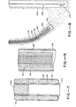
- Figure 1 is a side elevational view, partially in section, illustrating the system of the present invention and showing a pre-programmed turn of the eversible tube and central pipe of the system.
- Figure 2 is an enlarged, fragmentary cross-sectional view, partially schematic, of the top and bottom portions of the system of Figure 1.
- Figure 3 is a cross-sectional view taken along line 2-2 of Figure 2.
- Figure 4 is an enlarged cross-sectional view of a drilling head assembly at the forward end of the present system.
- Figure 5 illustrates an enlarged, fragmentary side elevational view of a turning segment of the eversible tube with pre-programmed darts thereon.
- Figure 6 illustrates a side elevational view partially in section, of a signal generating device in the forward end of the central port and a remote receiving station for receiving signals for locating the generating device.
- Figure 7 is an enlarged, cross-sectional view of the forward end of the central pipe with a gravel pack contained within the eversible tube to form a casing.
- Figure 8 illustrates the device of Figure 7 contained within an external conventional casing for serving as an interior gravel pack device.
- Figure 9 is a schematic representation of a drilling system using the principle of electrokinetics, in which one electrode is on a drilling head and the other electrode is on a remote casing.
- Referring to Figures 1, 2, and 3, the principles of operation of the present system are illustrated. Referring specifically to Figure 2, the drilling unit of this invention includes an eversible elongate tube, generally designated by the
number 100, which serves the function of a rolling diaphragm which moves forwardly in a manner to be described below.Tube 100 includes flexible, generally cylindrical outer and innertubular walls rollover area 106, capable of being moved forwardly. The tube is preferably formed of a high-strength permeable woven material or cloth. The outer and inner walls have an opening near their rearward ends and define anannular space 108 therebetween which serves as a passageway for driving fluid from a source to be described below. - Means is provided in the form of an
annular retaining ring 110 for securing the rearward end of the outer wall to a stationary support (not shown) in a fixed position relative to movement ofrollover area 106. Downstream ofretaining ring 110,inner wall 104 forms a tube which is carried forwardly by driving fluid inannulus 108. In a preferred embodiment,tube 100 is relatively non- expandable and so, to permitinner wall 104 to formouter wall 102 of larger diameter,wall 104 includes sufficient slack material to accommodate this transformation, to provide a relatively long outer wall, such as one having a final length of 200-300 feet or more. - Upstream or rearwardly from retaining
ring 110, along length 104a of flexibleinner wall 104 may be collected in a relatively small space as by nesting in a pleated or accordion folded configuration, in an enlarged hollowtubular housing 112. Adriving fluid inlet 114 is provided in the space betweennested wall 104a and the outer wall ofhousing 112. The rearward end ofinner wall 104a is suitably sealed to the inner wall ofhousing 112 atring 116 upstream ofinlet 114. By nestingwall 104a in the illustrated manner, it readily feeds through the annulus of retainingring 110 without creating undue resistance to the forward movement ofrollover area 106. To prevent a portion of nestedinner wall 104a from uncontrollably falling through retainingring 110 under the influence of gravity, a suitable retaining device, not shown, may be inserted inhousing 112. Alternatively, the driving fluid directed toport 114 may be pressurized to a higher pressure than a pressurized fluid directed to aninlet 118 communicating with the interior ofwall 104a to presswall 104a inwardly against acentral pipe 122 extending throughtube 100 and to be described below. - A
central passageway 120 is defined to the interior ofinner wall 104.Central pipe 122 extends inpassageway 120 throughtube 100 to at least the forward end of the central passageway adjacent torollover area 106. Pipe 122 serves a number of functions, including as an internal support or as an ultimate strong casing for the bore hole to be drilled with the present invention, and as a means for directing the drilling apparatus as described below. In a preferred embodiment, it is adapted to be carried forwardly by frictional contact with the adjacent surface ofinner wall 104 and by drivingfluid entering inlet 118. As illustrated,central pipe 122 is hollow and defines aninternal channel 124 for directing drilling fluid from a second source out the forward end of the central pipe and against the earth formation to be drilled. - Referring again to Figure 2, a forward
directional stabilizer 126 is provided in the form of an outertubular shroud 128 and spacedradial fins 130, mounted to the forward end ofcentral pipe 122. Shroud 128 is of slightly larger diameter thanouter wall 102 and extends axially and concentrically along the wall, a distance preferably 1-4 times the diameter oftube 102. Asrollover area 106 moves forward, it bears against the rearward surfaces offins 130 and ofshroud 128 to move the shroud forward. Fins 130 are preferably of radially disposed spoke-like configuration, each spoke extending a distance along the axis of the shroud. - Referring to Figure 3, in a preferred embodiment, outer and
inner walls central pipe 122 are circular in cross section in concentric relationship with each other defining spaces therebetween. - Referring again to Figures 1 and 2, a driving fluid is directed from a
source 132 to apump 134 intoinlet 114 in the direction of arrows A. Simultaneously, drilling fluid from asource 136 is directed throughpump 138 throughannulus 140 ofcentral passageway 120, defined to the exterior ofpipe 122 and the interior ofwall 104, while a second source ofdriving fluid 142 is directed throughpump 144 to the center of generally flexiblecentral pipe 122 wound on a spool inreel housing 146. Aroller 148 may be provided to turn flexiblecentral pipe 122 from a horizontal to a vertical direction for downward movement throughannular retaining ring 110 into the device. - Referring specifically to Figure 2, in operation, driving fluid A is pumped into the
space 108 betweenwalls rollover area 106. Becauseouter wall 102 is fixed atring 110, the inner wall moves downwardly and undergoes a transformation in shape to become the outer wall at the rollover area to create forward movement of the rollover area. - Referring again to Figures 1 and 2, drilling fluid from the surface is directed through
annulus 140, in a direction generally designated by arrow B, and throughchannel 124 ofpipe 122 as illustrated by arrow C, to create a fluidized slurry zone D created by mechanical, fluid mechanical, thermal, and physical-chemical interactions of the drilling fluid with the surrounding formation. For drilling in an oil-bearing formation, it is preferable to use a drilling fluid which serves to fluidize the oil in a continuous oil or water phase, as described more fully below. In any event, the fluidized zone of slurry, designated "D" in Figure 2, is created forwardly ofrollover area 106, and anouter annulus 150 betweenouter wall 102 and the surrounding formation is created during drilling and permits the movement of a slurry of cuttings in the direction of arrows E. When the slurry reaches the surface or other suitable location, it may be pumped throughline 152 viapump 154 into asump 156 at thesurface 158 of the formation. Preferably, a suitable conventional support assembly andfoundation 159 is provided in the ground to house and support the upstream end of the system. As illustrated in Figure 1, an important feature of the present invention is the ability to turneversible tube 100 in a predetermined direction, such as to bend it to a horizontal direction, and even to turn again, as toward the surface. - Another important feature of the invention is the lubrication inherently provided by the pressure of a guide fluid in the annular space between inner
tubular wall 104 andcentral pipe 122. The guide fluid may be supplied fromsource 118 and/or by weepage throughinner wall 104 where that wall is liquid permeable (e.g., by formation from a cloth fabric of the desired permeability). The resulting lubrication permits low friction sliding movement betweeninner wall 104 andcentral pipe 122 to permitinner wall 104 to move forward at a velocity twice that ofcentral pipe 122. - The system of the present invention may include a technique of first drilling a main bore hole into an underground formation with a conventional rotary drill, withdrawing the drill, casing the main drill hole, and thereafter forming one or more lateral bore holes projecting from the main bore hole by the system illustrated in Figures 1 and 2.
- Referring to Figure 4, an expanded view of the forward end of the
eversible tube 100 is illustrated with driving fluid in thetube 100 indicated by the arrow A inannular portion 108. As illustrated, guide and drilling fluids moving in the direction of arrows B and C, respectively, are pumped downwardly throughcentral pipe 122 and the zone betweeninner wall 104 andcentral pipe 122. One preferred form ofcentral pipe 122 includes aforward segment 122a of a relatively rigid and nonporous material connected at its rearward end to a .flexible metallichelical segment 122b capable of bending or flexing to change direction in response to application or a bending moment tosegment 122b.Helical segment 122b is liquid permeable and, as set forth below, is capable of forming an interior permeable support wall for casing the bore hole, which is drilled by drilling fluid passing throughcentral pipe 122. - The degree of flexibility of portions of
central pipe 122 have a significant effect on the ability of the central pipe and the eversible tube normally to track in a straight line and to readily turn when a preprogrammed guidance mechanism carried by the central pipe is actuated. With respect to straight line movement, it is desirable for the forward end of the central pipe to be relatively rigid or stiff. On the other hand, in the area of the central pipe desired for the turn, it is preferable that such pipe be sufficiently flexible to make the turn, but yet be sufficiently rigid to provide a strong framework for use as the ultimate casing of the resulting bore hole. Referring to Figure 4, an excellent flexible material for this purpose is a cylindricalsteel helix segment 122b. It has been found that for axial stability it is preferable.to include a rigidforward segment 122a of the central pipe, having a length about 5 to 25 times the diameter ofinner wall 104. The maximum length of the rigid portion is determined by the radius of curvature of the desired bore hole which is acceptable during drilling. That is, ifforward end 122a is totally rigid, the curvature is determined by the cord distance between the forward edge ofcentral pipe 122 along a diagonal line to the end of the rigid portion. - Referring to Figures 1 and 4, an embodiment of the invention using a drilling head, generally designated by the
number 160, is illustrated schematically. The requisite pressure and flow of drilling fluid in the central pipe is considerably reduced by the use of flow restricting orflow distributing ports 164 indrilling head 160. - The port or
ports 164 may be spaced around the periphery of the head. The interior ofhead 160 is a hollow cavity in fluid communication withchannel 124. The port orports 164 are adapted to pass and distribute drilling fluid. - The flow rates of drilling fluid through
head 160 may vary substantially, depending upon the type of surrounding formation and the particular type of drilling fluid. However, for example, in a 2 inch diameter drill head it has been found that a suitable flow velocity is from 1 to 10 feet/second. - Referring again to Figure 4, one mode of mounting the
drilling head 160 topipe 122 is illustrated. There, acylindrical shroud 166 is provided suitably connected to head 160 by threadedconnection 168. Similarly,shroud 166 is connected at an intermediate, internal end to the forward end ofpipe 122 by threadedconnection 170. In essence,shroud 166 is an interconnecting member betweenhead 160 andpipe 122. It is hollow to permit the flow of driving fluid throughpipe 122 and intohollow head 160, and to permittube 100 circumferential area to roll over and provide or obtain support forhead 160 fromtube 100. - A
cylindrical shroud 166 is provided which includes an outer, relatively thin, cylindricalrear wall 166a, extending rearwardly from anannular seating ring 166b. The force of driving fluid inannular space 120 againstrollover area 106 is applied against the rear flat face ofseating ring 166b to urge it forwardly in response to the driving fluid pressure exerted against the rollover area. - Driving fluid is leaked out into the backflow channel along the
outer wall 102 ofeversible tube 100, by forming the tube of a cloth fabric of the desired permeability. Similarly, driving fluid leaks inwardly throughinner wall 104 to provide low friction sliding movement between such inner wall and the central pipe. This leakage, together with flowing liquid between thecentral pipe 122 andwall 104, provides a source of liquid exiting from the rearward end ofshroud wall 166, in a generally rearward direction along the axis of the central pipe, as illustrated by arrow F in Figure 4. This provides increased fluidity at that point to assist rearward movement of the cuttings slurry. - Referring again to Figure 4, a pattern of effect on the surrounding underground formation is illustrated, where the drill head is moving in a generally horizontal direction. It has been found that the area designated by the letter G, directing surrounding
head 160 in the vicinity of the ports, causes the formation of cuttings, which mix with the drilling fluid to provide a movable slurry. The major portion of the cuttings are formed aroundhead 160. The cuttings and drilling fluid likewise form a fluidized slurry disposed generally aroundhead 160. Such slurry is directed over the surface of thedrilling head 160 and rearwardly in a channel exterior to the central pipe, generally parallel to its axis. - Immediately outside of this fluidized slurry is an area H in which the formation pore pressure may be affected by the drilling fluid to facilitate the movement of the drill head through the formation.
- Figure 4 illustrates a beneficial phenomenon which occurs when the
drill head 160 is travelling in a horizontal direction. That is, a pedestal of heavier particles naturally forms below the drilling head, in comparison to those particles present above it. This pedestal, generally designated by the letter I, is formed by the sorting and deposit of larger, heavier particles from the slurry traveling rearwardly, analogous to a moving concrete slip form. This pedestal provides support and corresponding stability of motion to head 160 in the horizontal direction. - As further illustrated in Figure 4, at the rearward end of
shroud 166, the flow of fluid backward and upward along along the arrow E causes a progressive and continuous reforming of this pedestal formation I. The heavier drill cuttings progressively precipitate in a graded arrangement below the drill tube to create a strong foundation beneath it. The slurry of lighter cuttings moves along the top oftube 100 or direction E to reach the surface. - The illustrated
drilling head 160 has a number of significant advantages. For different formation materials, the density of the head may be varied relative to the shroud. If, in a particular formation, the head tends to travel in an upward direction by floating, rather than in a desired horizontal direction, this may be counteracted in subsequent drilling by forming the head from a relatively dense material. Conversely, if the drill tends to dive' rather than rise, the density of the material may be decreased in subsequent drilling in that formation. - Referring in general to Figure 5, one mode for causing a turn to be made by
tube 100 is illustrated in whichtube 100, in effect, includes a turning segment formed axially in the tube, initially disposed oninner tube wall 104 and then moving throughrollover area 106 to the outer tubular wall. The most desired material for this type of turning mechanism is a strong 'woven fabric- like material, woven in a normal weave configuration, illustrated assegment 172 in Figure 5. This type of configuration avoids twisting of the material because the minimum energy condition is for the axial (warp) part of the fibers to remain axial while the other fibers (fill) remain circumferential. It has been found that tubular cloth material of this type does not twist with the individual axial fibers in a highly stable axial direction, so that the turning segments remain in the same angular orientation with respect to the axis of thetube 100 during drilling. This means that a preprogrammed turn using a tube of this type is highly predictable. Suitable high strength fibers for use with the tube can be of the nylon or aramid (aromatic polyamide) type which may be further reinforced. Suitable aramid materials are sold under the trademark Kevlar 29 or 49, by Du Pont. Other high strength fibers may be used alone or in combination with the nylon or aramid fibers in the warp or fill directions. - Referring again to Figure 5, the turning segment of
tube 100 includes axially spaced strip-like portions (darts) of shortened effective circumferential length compared to the circumference of the turning segment which causes the tube to turn in the direction of the shortened strip-like portion when theinner wall 104 oftube 100 moves through the rollover area. The shortened strip-like portions 5 formed by multiple circumferential sewed-in tucks or darts 174, spaced apart axially a predetermined distance along a predetermined partial circumferential distance of the turning segment to provide a turn of the desired radius. Each of the darts, in essence, result from the sewing of a small segment of cloth from the outer fabric surface oftube 100 itself, representing a circumferential fin, which can be as short as a few degrees circumferentially to as long as 180 degrees circumferentially. The effect is to create a shortened side of thetube 100 so that when theinner wall 104 passes throughrollover area 106 and becomes theouter wall 102, it exposes a series of darts as illustrated in Figure 5 to cause the turn to be made. - Referring to Figure 4, it is preferable to include a permeable or impermeable
outer liner 176 oncentral pipe 122 which serves two distinct functions. Assuming it is desired to maintain differential pressures in drilling fluids travelling through and aroundcentral pipe 122, the liner may be impermeable to separate these flows. In addition, the liner provides protection against the darts hooking intohelical spring 122b while they are on the inner wall. - Referring to Figure 6, locating means for the central pipe is illustrated.
Means 180 for generating a signal, such as of the acoustical, electrical, electromagnetic or seismic type, is mounted at the forward end ofcentral pipe 122 and serves as a transponder. Means is provided for receiving or sensing the signal atsurface stations 182 to locate the forward end on a triangulation basis. - If desired, a fluid pressure actuated rotating drill (such as a Moineau motor used as a drill motor of the type sold under the trade designation Dyna-Drill, by Smith International, Inc. of Irvine, California) may be mounted to the forward end of
central pipe 122 to break up limited amounts of consolidated formation. Such drill is either placed down the bore hole only if needed or may be permanently mounted but not actuated until consolidated material is reached. The drilling fluid passes throughcentral pipe 122 and into the formation. - A variety of different drilling fluids.may be used, such as aqueous or oil-based fluids, and a range of low to high viscosity fluids. Oil or an oil-based solvent can be used to facilitate penetration into certain formations. In other formations, it may be desirable to use an aqueous- based drilling fluid to emulsify the oil phase.
- One preferred aqueous drilling fluid includes an aqueous monovalent alkali metal (e.g., sodium) hydroxide or salt solution at an alkaline pH of at least 8.5, and preferably 11.0. This system is found to form a surfactant in situ by reaction with the organic acids in the oil to thereby assist breaking up the structure of the formation and to form a slurry. In addition, the base serve as sources of high ionic strength to accomplish the beneficial effects of emulsive destabilization of the oil-water interface as set out above. In that regard, salts such as sodium chloride in salt water may help serve a similar destabilizing effect but may cause other problems. Another drilling fluid system includes as a surfactant sulfonated salts of oil molecules.
- Referring to Figure 7, another embodiment of the present invention is illustrated, including a conventional
gravel pack material 184, which is pumped into the interior oftube 100, forcing out the driving fluid after the bore hole is completed. Such gravel pack filters out sand so that it does not back fill into the cased well bore. In that regard, it is preferable to form the central pipe of a flexible steel helix with turns spaced approximately 0.015 to 0.030 in. apart to provide a support structure for the gravel pack and thereby form a production system in place. This same technique could be used for thermal insulation of a casing by substitution of a fluid material, which is thermally insulative in'place, for the gravel pack. - In another embodiment, illustrated in Figure 8, the system of the present invention is passed downwardly into a conventional
bore hole casing 186, e.g. formed of a slotted liner, then gravel filled to provide gravel packing 188 in a conventionally drilled bore hole. - Referring again to Figure 1, an overall central backbone-
like arrangement 190 includes at least a section which limits movement of the drill head assembly to a fixed plane while allowing the assembly to freely move in a curved or linear fashion within that plane: A plurality of relativelyrigid tubes 192 are interconnected in an end-to-end fashion by means of substantiallyrectangular tabs 194. All of the tabs are oriented in the same direction and are constructed of plastic, sheet metal or like material which allows each tab to bend about an axis across its width while not being freely bendable in any other direction. In this way, it functions like a backbone to provide free bending movement in one plane only. - In the embodiment of Figure 9, the principle of electrokinetics is applied to the present invention by the application of an electric field. Such field may cause the migration of water toward the vicinity of the forward end of the drilling system to assist in the formation of a slurry and thereby facilitate drilling. It is well known that in a subterranean formation, when a direct current is applied between an anode and a cathode, water tends to migrate towards the cathode. This phenomenon is known as electroosmosis. Thus, one important embodiment of the invention is to dispose a cathode on or near the forward end of the drilling system to cause water to migrate there. It may be possible to cause the same migration to occur using alternating current.
- The use of an electric field under the present invention also applies to the migration of charged particles. This is significant, as an underground formation contains many charged particles. For example, clay is typically negatively charged. Thus, by applying a negative charge to the forward end of the drilling system, the resistance to penetration is reduced not only by tending to attract water, but also by tending to repel the clay and other negatively charged particles in its vicinity and increase pore pressure ahead of the drill.
- Referring again to Figure 9, the forward end of a drilling head, of the type illustrated in Figure 4, is formed of an electrically conductive material, such as metal, and is connected by an
insulated lead wire 220 to the negative side of a direct current generating source at the surface, not shown. Spaced apart from the drilling system as set forth above, is avertical drill hole 222. Anelectrode 224 is connected to aninsulated lead wire 226, which is connected to the positive side of a direct current power source, not shown. By the application of this direct current source, the water migrates toward the negatively chargeddrill head 160 to facilitate movement of the pipe through the soil. In this manner, the current provides a path of least resistance towardsanode 222, which is buried to a predetermined depth in the well casing remote fromdrill head 160. An important advantage of this configuration is apparent when the drilling system is turned from a vertical to a horizontal or sloping position towardcasing 222, by a turning technique of the type set forth in the first-named patent application. Specifically, the electric field not only generally lowers resistance of the formation to penetration of the drill head, but also causes movement of the drilling head, preferentially toward the well casing because the lowered resistance is in a path fromdrilling head 166 toanode 224. Thus, additional guidance assistance is provided by the present system. - In another procedure using the general configuration of Figure 9,
drilling head 160 is positively charged andelectrode 222 is negatively charged. Aqueous sodium hydroxide is pumped into the formation so that the sodium ions are pumped away from the drilling head towardbore hole 222. In essence, this system serves as a sodium pump. Such sodium ions form surfactants in situ with the carboxyl groups of petroleum deposits in the formation to facilitate removal of the petroleum. In a related process, a sodium chloride salt water solution is either already present in the formation or is pumped into it through the drill head. In the present electric field, the sodium ion of the salt ionizes and migrates toward the drill head to create a surfactant with the petroleum deposits in a similar manner. - In another embodiment (not shown), the position of the drilling head may be monitored with a conventional hydrostatic pressure transducer mounted adjacent to or on the drill head for movement therewith. This transducer provides a reading of the hydrostatic pressure at the drill head which, in turm, can be readily converted to the depth at which the drill head is located relative to ground level. To this end, suitable signal carrying wire means would be provid ed from the transducer to ground level. The position mo nitoring arrangement also includes a single gauge for measuring a length of cable arrangement as the latter is drawn into the ground with the drill head.
- The overall position monitoring arrangement includes a plurality of electrodes including a moving electrode connected adjacent to or mounted on the drill head, and a plurality of fixed electrodes positioned above ground in a spaced relationship to one another to form a somewhat rectangular grid. Suitable electrical means are provided to maintain a voltage potential between the moving electrode and each of the fixed electrodes. With the moving electrode at any given depth level relative to ground, the relative potential between this electrode and the fixed electrodes will depend upon the distance between these electrodes.
- A further disclosure of the nature of the present invention is illustrated by the following specific example:
- A laboratory scale model of the system of the present invention is built as follows: The drill assembly includes a central pipe with a rigid, forward central pipe segment, formed of flexible tubing of a diameter in the following range: 0.5 in. to 1.5 in. The central pipe is connected at its rear end to a flexible, polyethylene pipe segment of the same diameter. An outer, flexible double-layered eversible tube is formed about the central pipe segment and is of nylon cloth. The expanded diameter of the nylon tube is in the range of 2.0 in. to 4.0 in. OD.
- A drilling head assembly generally of the type illustrated in the drawings is used. The
forward portion 160 is formed of brass and has a maximum diameter of about 2.0 in. to 4.0 in. - The system is placed vertically into a sand formation, and water is flowed through the central p'i.pe at an inlet flow rate of 7 to 8 gpm for sand. Water is also flowed through the annulus of the flexible pipe at 10 to 20 gpm and 30 to 50 psi. Some drilling fluid diffuses radially inwardly and outwardly. The central pipe advances through the sand at 0.01 to 0.05 feet/second.
- A turning segment, for turning
tube 100 from vertical to horizontal, is provided in the eversible tube. When the segment reaches the rollover, the tube turns from vertical to horizontal. - In general, the slurry formed at the forward area around
drill head 160 flows back along the outer surface of the eversible tube in a channel along the pipe. The backward flow of slurry is assisted by any leakage of driving fluid through the porous eversible tube.
Claims (31)
1. Apparatus for drilling a bore hole in an underground formation comprising: an eversible tube having an inner and outer wall defining a space therebetween for receiving a fluid under pressure, the walls being coupled together at one end of the tube to present a rollover area which is advanced in one direction to increase the length of the tube when the space is pressurized by said fluid; means coupled to the outer wall for securing the same to the adjacent formation; and a central pipe within the inner wall and movable in said one direction as a function of the advancement of said rollover area, said central pipe having a fluid outlet near the rollover area and adapted to be coupled to a source of drilling fluid under pressure to permit drilling fluid to be directed through the pipe and out of the outlet for drilling the formation in advance of said rollover area to continuously form a bore hole.
2. Apparatus as claimed in Claim 1 in which said central pipe includes a flexible helix section.
3. Apparatus as claimed in Claim 1 or Claim 2 in which said central pipe is flexible and extends outwardly from said tube means past said retaining means and is coiled for storage at its extended end.
4. Apparatus as claimed in Claim 1 or Claim 2 or Claim 3 in which said inner wall extends posteriorly past said retaining means and is nested for storage in a pleated configuration at its posterior end.
5. Apparatus as claimed in any preceding claim in which said central pipe comprises a drill hole casing.
6. Apparatus as claimed in any preceding claim together with means for causing a predetermined bending of the central pipe to effect a chance in direction of movement of the central pipe as the rollover area moves forwardly.
7. Apparatus as claimed in Claim 6 in which said causing means comprises a turning segment forming part of said tube, said turning segment including an axially extending strip-like portion having an axial length less than that of the remainder of said turning segment, whereby said tube is caused to turn in the direction of the side of the turning segment having said shortened strip-like portion when said turning segment moves through said rollover area.
8. Apparatus as claimed in Claim 7 in which said shortened strip-like portion is formed by a number of axially spaced darts, each dart extending partially about said turning segment circumferentially thereof.
9. Apparatus as claimed in any preceding claim in which said tube means is formed of a liquid permeable woven fabric material.
10. Apparatus as claimed in any preceding claim together with backbone means disposed in said central pipe, said backbone means being constructed to allow said drill head means to move in a curvilinear path while limiting said movement to a single, predetermined plane.
11. Apparatus as claimed in any preceding claim together with locating means for the forward portion of said apparatus comprising means for generating a signal, said signal generating means being mounted to said central pipe, and means for receiving said signal at multiple stations remote from said generating means.
12. Apparatus as claimed in any preceding claim together with fluid pressure actuated rotating drill head means mounted at the forward end of said central pipe.
13. apparatus as claimed in any preceding claim, herein said inner wall is spaced from said pipe to form a fluid passage, said passage adapted to be coupled with a source of drilling fluid to permit the drilling fluid to flow through the passage as said rollover area is advanced.
14. Apparatus as claimed in any preceding claim together with flow restricting and distributing drilling head adjacent the forward end of said central pipe having one or more port means adapted to pass drilling fluid.
15. Apparatus as claimed in Claim 14 in which said drilling head includes a generally cylindrical extension shroud mounted concentric with and extending back over the rollover end of a portion of said outer wall.
16. An in situ drill hole casing comprising a permeable hollow flexible steel helix submerged in the earth.
17. A casing as claimed in Claim 16 together with a liquid permeable particulate packing, capable of filtering solids of a predetermined size, surrounding said helix.
18. A casing as claimed in Claim 17 together with a liquid permeable fabric sheath surrounding said helix.
19. A casing as claimed in Claim 18 together with a thermally insulating material surrounding said helix.
20. The method of forming an underground bore hole using an apparatus comprising an elongate eversible rolling diaphragm with outer and inner walls interconnected at their forward end by a rollover area and being open at the other end, said outer wall being restrained, said inner wall defining to its interior a central passageway, an annular space for driving fluid being provided between said outer and inner walls, a hollow central pipe being provided in said central channel to extend proximal to said rollover area, said method comprising the steps of
(a) positioning the apparatus so that the rollover area projects into a proximal underground formation,
(b) directing drilling fluid through said central pipe to drill the formation to form cuttings of the formation and a slurry containing said cuttings at the proximal underground formation of increased susceptibility to penetration,
(c) directing driving fluid through said driving fluid annular space to bear against said rollover area and to cause the inner wall adjacent said rollover area to progressively undergo a transformation in shape and become the outer wall to move the rollover area forwardly into the thus-formed slurry in the earth formation, and
(d) carrying said central pipe forward in said central passageway as a function of the forward movement of said rollover area.
21. A method as claimed in Claim 20 together with the step of substantially changing the direction of travel of said rolling diaphragm during its forward movement.
22. A method as claimed in Claim 20 or Claim 21 together with the step of tracking said apparatus path by generating a signal at the forward end of said central pipe and receiving said signal at multiple remote stations.
23. A method as claimed in Claim 20 or Claim 21 or Claim 22 in which a flow restricting and distributing drilling head is provided adjacent the forward end of said central pipe and includes port means, in which the drilling fluid is directed through said port means into the formation.
24. A method of drilling a bore hole in an underground formation comprising: directing a drilling fluid continuously through and out of a movable pipe and against the formation to drill the formation to form cuttings of the formation, whereby a mixture of the drilling fluid and the cuttings of the formation define a slurry; moving the pipe progressively in one direction as the formation is drilling; and keeping the pipe out of substantial frictional engagement with the formation as the pipe moves in said one direction.
25. A cased bore hole comprising a hollow tubular casing disposed in a bore hole, a liquid permeable hollow central pipe disposed within said casing, said casing and pipe defining an annulus therebetween, and a tubular porous fabric sheath disposed in said annulus with interstices of a size to pass fluids but retain solids larger than a predetermined size.
26. A method of drilling in an underground formation to form downwardly directed cased bore hole and a lateral bore hole projecting from said main bore hole at a predetermined depth thereof, comprising the steps of first excavating the earth formation to form a main drill hole using with a rotating drill and emplacing a casing in said drill hole, and thereafter pumping a drilling fluid continuously through said cased main bore hole and through and out a movable pipe laterally projecting from said main bore hole to drill the formation in a lateral direction and form cuttings therein, whereby a mixture of the drilling fluid and the cuttings of the formation define a slurry; moving the pipe progressively in a lateral direction as the formation is drilled in its path; and keeping the pipe out of substantial frictional engagement with the formation as the pipe moves in its path.
27. Apparatus for forming a bore hole in an underground formation, comprising:
(a) a hollow pipe for carrying drilling fluid and having a forward end;
(b) means for supplying drilling fluid under pressure to said pipe;
(c) means for moving the pipe forward through the formation;
(d) a first electrode disposed near the forward end of said pipe for contact with said formation;
(e) a second electrode spaced from said first electrode, also disposed for contact with said formation; and
(f) means for generating an electric current between said first and second electrodes.
28. The method of forming an underground bore hole in a water-containing underground formation, said method comprising the steps of directing a drilling fluid under pressure through a movable hollow pipe and out the forward end of the pipe to flow into adjacent formation to drill the formation and to form cuttings of the drilled formation, whereby a mixture of the drilling fluid and cuttings will define a slurry; passing an electric current between spaced first and second electrodes while both electrodes are in contact with the formation, with the first electrode being near the forward end of the pipe; and moving the pipe progressively forwardly through the formation as said electrical current is passed between said electrodes.
29. The method of Claim 28 in which said first electrode is an anode and said second electrode is a cathode, together with the step of pumping an aqueous sodium hydroxide solution into said formation, whereby the sodium ions of the sodium hydroxide are repelled by the cathode toward the anode.
30. The method of Claim 28 in which said first electrode is an anode and said second electrode is a cathode, and salt water solution of sodium chloride is present in the pathway therebetween, whereby sodium ions of the sodium chloride are repelled by the cathode toward the anode.
31. An apparatus for forming a bore hole in an underground formation, comprising:
(a) drilling head means;
(b) means for moving said drilling head means through the ground from a fixed point above the ground, said moving means including a transmission line extending from said drill head means to said fixed point; and
(c) means for aiding in monitoring the position of said drill head when the latter is underground, said aiding means including a pressure transducing device positioned at fixed location in close proximity to said drilling head means, whereby, to indicate the hydrostatic pressure at said location so as to fix the vertical depth of said drilling head means, means for measuring the actual distance along said transmission line between said drilling head means and sa.id fixed point above ground, and means for determining the common vertical plane in which both said drilling head means and said fixed point above ground are located.
Applications Claiming Priority (2)
| Application Number | Priority Date | Filing Date | Title |
|---|---|---|---|
| US169759 | 1980-07-17 | ||
| US06/169,759 US4431069A (en) | 1980-07-17 | 1980-07-17 | Method and apparatus for forming and using a bore hole |
Publications (2)
| Publication Number | Publication Date |
|---|---|
| EP0044706A2 true EP0044706A2 (en) | 1982-01-27 |
| EP0044706A3 EP0044706A3 (en) | 1982-12-22 |
Family
ID=22617060
Family Applications (1)
| Application Number | Title | Priority Date | Filing Date |
|---|---|---|---|
| EP81303257A Ceased EP0044706A3 (en) | 1980-07-17 | 1981-07-15 | Method and apparatus for forming and using a bore hole |
Country Status (17)
| Country | Link |
|---|---|
| US (2) | US4431069A (en) |
| EP (1) | EP0044706A3 (en) |
| JP (1) | JPS5751390A (en) |
| KR (1) | KR850001292B1 (en) |
| AT (1) | ATA312781A (en) |
| AU (1) | AU7286381A (en) |
| BE (1) | BE889662A (en) |
| BR (1) | BR8104608A (en) |
| CA (1) | CA1182104A (en) |
| DE (1) | DE3127337C2 (en) |
| ES (1) | ES8305874A1 (en) |
| FR (1) | FR2493394A1 (en) |
| GB (1) | GB2080369B (en) |
| IL (1) | IL63301A0 (en) |
| IT (1) | IT1137726B (en) |
| SE (1) | SE8104241L (en) |
| ZA (1) | ZA814751B (en) |
Cited By (25)
| Publication number | Priority date | Publication date | Assignee | Title |
|---|---|---|---|---|
| FR2556404A1 (en) * | 1983-09-08 | 1985-06-14 | Lucet Raymond | "Self-supporting" (elastomeric) hose more especially used as support and suction/discharge pipe capable of carrying submerged pumps |
| WO1993008367A1 (en) * | 1991-10-14 | 1993-04-29 | Insituform Group Limited | Improvements relating to the placement of pipes in the ground |
| WO2008006841A1 (en) | 2006-07-13 | 2008-01-17 | Shell Internationale Research Maatschappij B.V. | Method of radially expanding a tubular element |
| WO2009074633A2 (en) * | 2007-12-13 | 2009-06-18 | Shell Internationale Research Maatschappij B.V. | Method of expanding a tubular element in a wellbore |
| WO2009074643A2 (en) * | 2007-12-13 | 2009-06-18 | Shell Internationale Research Maatschappij B.V. | Method of creating a wellbore system |
| WO2009074632A2 (en) * | 2007-12-13 | 2009-06-18 | Shell Internationale Research Maatschappij B.V. | Wellbore system |
| US20100252333A1 (en) * | 2007-12-10 | 2010-10-07 | Blange Jan-Jette | System for drilling a wellbore |
| CN101910554A (en) * | 2008-01-04 | 2010-12-08 | 国际壳牌研究有限公司 | Method of drilling a wellbore |
| CN102071874A (en) * | 2011-01-12 | 2011-05-25 | 中国石油集团川庆钻探工程有限公司 | Drilling method suitable for gravel area |
| US8056641B2 (en) | 2007-10-23 | 2011-11-15 | Shell Oil Company | Method of radially expanding a tubular element in a wellbore provided with a control line |
| US8056642B2 (en) | 2007-10-29 | 2011-11-15 | Shell Oil Company | Method of radially expanding a tubular element |
| US8141647B2 (en) | 2006-11-21 | 2012-03-27 | Shell Oil Company | Method of radially expanding a tubular element |
| WO2012059574A1 (en) | 2010-11-04 | 2012-05-10 | Shell Internationale Research Maatschappij B.V. | System and method for radially expanding a tubular element |
| EP2460972A1 (en) | 2010-12-03 | 2012-06-06 | Shell Internationale Research Maatschappij B.V. | Method and system for radially expanding a tubular element |
| US8196669B2 (en) | 2007-11-21 | 2012-06-12 | Shell Oil Company | Method of drilling a wellbore |
| WO2012095472A2 (en) | 2011-01-14 | 2012-07-19 | Shell Internationale Research Maatschappij B.V. | Method and system for radially expanding a tubular element and directional drilling |
| US8267184B2 (en) | 2007-11-22 | 2012-09-18 | Shell Oil Company | Method of radially expanding a tubular element |
| US8275551B2 (en) | 2006-11-22 | 2012-09-25 | Shell Oil Company | Method of imaging of seismic data involving a virtual source, methods of producing a hydrocarbon fluid, and a computer readable medium |
| US8387709B2 (en) | 2007-12-13 | 2013-03-05 | Shell Oil Company | Method of expanding a tubular element in a wellbore |
| US8408318B2 (en) | 2007-12-13 | 2013-04-02 | Shell Oil Company | Method of expanding a tubular element in a wellbore |
| US8430177B2 (en) | 2008-01-04 | 2013-04-30 | Shell Oil Company | Method of expanding a tubular element in a wellbore |
| CN101883909B (en) * | 2007-12-04 | 2013-06-12 | 国际壳牌研究有限公司 | Method of radially expanding a tubular element |
| US8479843B2 (en) | 2007-12-11 | 2013-07-09 | Shell Oil Company | System for drilling a wellbore |
| WO2013167521A1 (en) * | 2012-05-08 | 2013-11-14 | Shell Internationale Research Maatschappij B.V. | Method and system for sealing an annulus enclosing a tubular element |
| CN103758454A (en) * | 2014-01-21 | 2014-04-30 | 河南理工大学 | Pore forming, pit building, powder stamping and pressure relief integrated device in soft coal development area |
Families Citing this family (78)
| Publication number | Priority date | Publication date | Assignee | Title |
|---|---|---|---|---|
| MX159238A (en) * | 1982-07-26 | 1989-05-08 | Dickinson Ben Wade O Iii | IMPROVEMENTS IN THE SOIL DRILLING DEVICE, FOR EXAMPLE FOR OIL WELLS |
| ZA835245B (en) * | 1982-07-26 | 1984-08-29 | Dickinson Ben Wade O Iii | Earth drilling apparatus and method |
| US4605076A (en) * | 1984-08-03 | 1986-08-12 | Hydril Company | Method for forming boreholes |
| US4624327A (en) * | 1984-10-16 | 1986-11-25 | Flowdril Corporation | Method for combined jet and mechanical drilling |
| BE905265A (en) * | 1986-08-13 | 1986-12-01 | Smet Nik | METHOD AND APPARATUS FOR MAKING A HOLE IN THE GROUND. |
| US4852666A (en) * | 1988-04-07 | 1989-08-01 | Brunet Charles G | Apparatus for and a method of drilling offset wells for producing hydrocarbons |
| CA2002135C (en) * | 1988-11-03 | 1999-02-02 | James Bain Noble | Directional drilling apparatus and method |
| US5161626A (en) * | 1990-12-10 | 1992-11-10 | Industrial Engineering, Inc. | Method for embedding lines, anchoring cables, and sinking wells |
| GB2279998B (en) * | 1993-07-14 | 1997-04-09 | T & N Technology Ltd | Plain bearing |
| NL9301921A (en) * | 1993-11-05 | 1995-06-01 | Nacap Nederland Bv | Method and system for the exploration and extraction of raw materials, minerals or the like in soft soil. |
| US5513713A (en) * | 1994-01-25 | 1996-05-07 | The United States Of America As Represented By The Secretary Of The Navy | Steerable drillhead |
| AU4458797A (en) | 1997-09-15 | 1999-04-05 | Sofitech N.V. | Electrically conductive non-aqueous wellbore fluids |
| US6793025B2 (en) * | 1998-01-08 | 2004-09-21 | M-I L. L. C. | Double emulsion based drilling fluids |
| US6405809B2 (en) | 1998-01-08 | 2002-06-18 | M-I Llc | Conductive medium for openhold logging and logging while drilling |
| US6135215A (en) * | 1998-04-14 | 2000-10-24 | Ericksen; William R. | Tool string apparatus for lateral borehole formation |
| FR2787504B1 (en) * | 1998-12-18 | 2001-01-12 | Inst Francais Du Petrole | SYSTEM FOR THE PERMANENT INSTALLATION OF MEASUREMENT PROBES AGAINST THE INTERIOR WALL OF A DUCT |
| CA2271401C (en) * | 1999-02-23 | 2008-07-29 | Tesco Corporation | Drilling with casing |
| GB2377719B (en) | 2000-02-16 | 2004-08-25 | Performance Res & Drilling Llc | Horizontal directional drilling in wells |
| US6530439B2 (en) | 2000-04-06 | 2003-03-11 | Henry B. Mazorow | Flexible hose with thrusters for horizontal well drilling |
| AU5440401A (en) * | 2000-04-13 | 2001-10-30 | Kayoshi Tsujimoto | Equipments for excavating the underground |
| US6419020B1 (en) | 2001-04-24 | 2002-07-16 | Ben Spingath | Hydraulic drilling method and system for forming radial drain holes in underground oil and gas bearing formations |
| DE60221667D1 (en) * | 2001-06-18 | 2007-09-20 | Exxonmobil Res & Eng Co | DEVICE AND METHOD FOR HYDROTHERMIC DRILLING |
| CA2473323C (en) | 2002-01-17 | 2010-08-03 | Presssol Ltd. | Two string drilling system |
| WO2003062590A1 (en) | 2002-01-22 | 2003-07-31 | Presssol Ltd. | Two string drilling system using coil tubing |
| US6772847B2 (en) * | 2002-02-26 | 2004-08-10 | Bj Services Company | Chemically enhanced drilling methods |
| CA2508254C (en) | 2002-07-19 | 2010-07-27 | Presssol Ltd. | Reverse circulation clean out system for low pressure gas wells |
| US7204327B2 (en) * | 2002-08-21 | 2007-04-17 | Presssol Ltd. | Reverse circulation directional and horizontal drilling using concentric drill string |
| RU2239729C1 (en) * | 2003-11-20 | 2004-11-10 | Зиновий Дмитриевич Хоминец | Oil-well jet plant and method of its operation when logging horizontal wells |
| US7343983B2 (en) * | 2004-02-11 | 2008-03-18 | Presssol Ltd. | Method and apparatus for isolating and testing zones during reverse circulation drilling |
| US20050178586A1 (en) * | 2004-02-12 | 2005-08-18 | Presssol Ltd. | Downhole blowout preventor |
| US20060278393A1 (en) * | 2004-05-06 | 2006-12-14 | Horizontal Expansion Tech, Llc | Method and apparatus for completing lateral channels from an existing oil or gas well |
| US7357182B2 (en) * | 2004-05-06 | 2008-04-15 | Horizontal Expansion Tech, Llc | Method and apparatus for completing lateral channels from an existing oil or gas well |
| WO2006135565A2 (en) * | 2005-06-10 | 2006-12-21 | Exxonmobile Upstream Research Company | Thermal activation mechanisms for use in oilfield applications |
| EP1798370B1 (en) * | 2005-12-14 | 2008-07-23 | Services Petroliers Schlumberger | Methods and apparatus for well construction |
| US20080093125A1 (en) * | 2006-03-27 | 2008-04-24 | Potter Drilling, Llc | Method and System for Forming a Non-Circular Borehole |
| US7971658B2 (en) * | 2007-10-31 | 2011-07-05 | Buckman Sr William G | Chemically Enhanced Stimulation of oil/gas formations |
| US20090143844A1 (en) * | 2007-11-29 | 2009-06-04 | Gaymar Industries, Inc. | Hose management for convective devices |
| DE102008038964B4 (en) * | 2007-12-04 | 2013-11-28 | GIB - Gesellschaft für Innovation im Bauwesen mbH | Mobile device unit for generating a survey in trays and fillings |
| US7934563B2 (en) * | 2008-02-02 | 2011-05-03 | Regency Technologies Llc | Inverted drainholes and the method for producing from inverted drainholes |
| EP2103774A1 (en) * | 2008-03-20 | 2009-09-23 | Bp Exploration Operating Company Limited | Device and method of lining a wellbore |
| US8186459B1 (en) | 2008-06-23 | 2012-05-29 | Horizontal Expansion Tech, Llc | Flexible hose with thrusters and shut-off valve for horizontal well drilling |
| AU2009302290A1 (en) * | 2008-10-08 | 2010-04-15 | Potter Drilling, Inc. | Methods and apparatus for mechanical and thermal drilling |
| US8250847B2 (en) * | 2008-12-24 | 2012-08-28 | Lockheed Martin Corporation | Combined Brayton-Rankine cycle |
| WO2011011817A1 (en) * | 2009-07-28 | 2011-02-03 | Ausdrill Ltd | Drill apparatus |
| US9909783B2 (en) * | 2010-02-23 | 2018-03-06 | Robert Jensen | Twisted conduit for geothermal heat exchange |
| GB2500493A (en) * | 2010-11-04 | 2013-09-25 | Shell Int Research | System and method for radially expanding a tubular element comprising an emergency blow-out preventer |
| CN102155618A (en) * | 2010-12-31 | 2011-08-17 | 承德市开发区富泉石油机械有限公司 | Low-temperature-resisting petroleum pipeline |
| US9422795B2 (en) | 2011-07-07 | 2016-08-23 | Shell Oil Company | Method and system for radially expanding a tubular element in a wellbore |
| US10227825B2 (en) * | 2011-08-05 | 2019-03-12 | Coiled Tubing Specialties, Llc | Steerable hydraulic jetting nozzle, and guidance system for downhole boring device |
| CN103032024B (en) * | 2011-10-09 | 2016-08-24 | 湖南汉寿煤矿机械有限公司 | Mining continuous drilling machine |
| CN102374360B (en) * | 2011-11-29 | 2013-07-24 | 西南石油大学 | Hydraulic drive telescopic downhole tool running device of horizontal well |
| US9228738B2 (en) | 2012-06-25 | 2016-01-05 | Orbital Atk, Inc. | Downhole combustor |
| US9291041B2 (en) | 2013-02-06 | 2016-03-22 | Orbital Atk, Inc. | Downhole injector insert apparatus |
| WO2015030601A1 (en) * | 2013-08-27 | 2015-03-05 | Geovarme As | A geothermal energy plant and a method for establishing same |
| US20150107905A1 (en) * | 2013-10-16 | 2015-04-23 | Islander LLC | Hydraulic borehole mining system and method |
| US20150321125A1 (en) * | 2014-05-08 | 2015-11-12 | Baker Hughes Incorporated | Filter and related methods for use during wellbore operations |
| US9777557B2 (en) * | 2014-05-14 | 2017-10-03 | Baker Hughes Incorporated | Apparatus and method for operating a device in a wellbore using signals generated in response to strain on a downhole member |
| CA2958718C (en) | 2014-06-17 | 2022-06-14 | Daniel Robert MCCORMACK | Hydraulic drilling systems and methods |
| WO2016061470A1 (en) * | 2014-10-17 | 2016-04-21 | Frx, Inc. | An injection tip and method for nucleating and propagating hydaulic fractures from probe rods |
| US10329851B2 (en) | 2014-12-11 | 2019-06-25 | Halliburton Energy Services, Inc. | Sub for accommodating large devices |
| EP3034778A1 (en) * | 2014-12-18 | 2016-06-22 | Shell Internationale Research Maatschappij B.V. | System and method for expanding a tubular element |
| AU2015412351A1 (en) | 2015-10-23 | 2018-03-15 | Halliburton Energy Services, Inc. | Casing string assembly with composite pre-milled window |
| DE102016001779A1 (en) * | 2016-02-08 | 2017-08-10 | Stefan von den Driesch | Low-maintenance, reliable drill tool for trouble-free continuous operation for sinking automatically direction-monitored drill holes in subterranean rock formations |
| US10981108B2 (en) | 2017-09-15 | 2021-04-20 | Baker Hughes, A Ge Company, Llc | Moisture separation systems for downhole drilling systems |
| US11261678B2 (en) | 2019-12-10 | 2022-03-01 | Saudi Arabian Oil Company | Deploying wellbore patch for mitigating lost circulation |
| US11668143B2 (en) | 2019-12-10 | 2023-06-06 | Saudi Arabian Oil Company | Deploying wellbore patch for mitigating lost circulation |
| US11125046B2 (en) | 2019-12-10 | 2021-09-21 | Saudi Arabian Oil Company | Deploying wellbore patch for mitigating lost circulation |
| US11286733B2 (en) | 2020-03-26 | 2022-03-29 | Saudi Arabian Oil Company | Deploying material to limit losses of drilling fluid in a wellbore |
| US11643878B2 (en) | 2020-03-26 | 2023-05-09 | Saudi Arabian Oil Company | Deploying material to limit losses of drilling fluid in a wellbore |
| US11454071B2 (en) * | 2020-03-26 | 2022-09-27 | Saudi Arabian Oil Company | Deploying material to limit losses of drilling fluid in a wellbore |
| US11459838B2 (en) | 2020-06-10 | 2022-10-04 | Saudi Arabian Oil Company | Lost circulation fabric, method, and deployment systems |
| US11434707B2 (en) | 2020-06-10 | 2022-09-06 | Saudi Arabian Oil Company | Lost circulation fabric, method, and deployment systems |
| US11434708B2 (en) | 2020-06-10 | 2022-09-06 | Saudi Arabian Oil Company | Lost circulation fabric, method, and deployment systems |
| US11727555B2 (en) | 2021-02-25 | 2023-08-15 | Saudi Arabian Oil Company | Rig power system efficiency optimization through image processing |
| WO2022238666A1 (en) * | 2021-05-12 | 2022-11-17 | Reme, Llc | Fluid control valve for rotary steerable tool |
| US11624265B1 (en) | 2021-11-12 | 2023-04-11 | Saudi Arabian Oil Company | Cutting pipes in wellbores using downhole autonomous jet cutting tools |
| US11867012B2 (en) | 2021-12-06 | 2024-01-09 | Saudi Arabian Oil Company | Gauge cutter and sampler apparatus |
| WO2023235324A1 (en) * | 2022-06-01 | 2023-12-07 | Applied Exponential Technologies, Llc | Concentric channel ground heat exchanger |
Citations (9)
| Publication number | Priority date | Publication date | Assignee | Title |
|---|---|---|---|---|
| US2778603A (en) * | 1953-06-22 | 1957-01-22 | Oilwell Drain Hole Drilling Co | Preparation of well drain holes for production |
| US2822158A (en) * | 1949-03-05 | 1958-02-04 | Willard C Brinton | Method of fluid mining |
| US2825364A (en) * | 1954-10-14 | 1958-03-04 | Cullen | Flexible supports for fluid-driven drill bits |
| FR1256614A (en) * | 1960-02-10 | 1961-03-24 | Europ De Turboforage Soc | Method and equipment for protecting drilling tools against clogging |
| US3363705A (en) * | 1965-08-19 | 1968-01-16 | John J. Jensen | Core barrel inner tube |
| US3406766A (en) * | 1966-07-07 | 1968-10-22 | Henderson John Keller | Method and devices for interconnecting subterranean boreholes |
| US3746106A (en) * | 1971-12-27 | 1973-07-17 | Goldak Co Inc | Boring bit locator |
| US3853185A (en) * | 1973-11-30 | 1974-12-10 | Continental Oil Co | Guidance system for a horizontal drilling apparatus |
| US4153119A (en) * | 1978-04-10 | 1979-05-08 | Continental Oil Company | Directional drilling apparatus |
Family Cites Families (32)
| Publication number | Priority date | Publication date | Assignee | Title |
|---|---|---|---|---|
| US1367042A (en) * | 1919-12-08 | 1921-02-01 | Granville Bernard | Drilling apparatus |
| DE712533C (en) * | 1936-05-30 | 1941-10-21 | Siemens Schuckertwerke Akt Ges | Method of making boreholes in flexible, loose masses |
| US2258001A (en) * | 1938-12-23 | 1941-10-07 | Dow Chemical Co | Subterranean boring |
| US2271005A (en) * | 1939-01-23 | 1942-01-27 | Dow Chemical Co | Subterranean boring |
| US2382933A (en) * | 1941-12-16 | 1945-08-14 | John A Zublin | Method of drilling holes |
| US2344277A (en) * | 1942-01-27 | 1944-03-14 | John A Zublin | Method of drilling lateral bores |
| US2513944A (en) * | 1945-04-28 | 1950-07-04 | Texas Co | Method and apparatus for completing a well |
| US2565794A (en) * | 1945-10-02 | 1951-08-28 | Signal Oil & Gas Co | Directional drilling of deviated boreholes |
| GB657249A (en) * | 1949-11-05 | 1951-09-12 | Guy Liddell | Improvements in and relating to wellpoints and the like |
| US2743082A (en) * | 1950-05-29 | 1956-04-24 | John A Zublin | Method for drilling deviating bores from existing well bores |
| US2669430A (en) * | 1951-11-06 | 1954-02-16 | John A Zublin | Apparatus for drilling deviating bores utilizing a plurality of straight tubular drill guide sections |
| US2729294A (en) * | 1953-08-07 | 1956-01-03 | Carrol Vernon Radke | Well screen |
| US2804926A (en) * | 1953-08-28 | 1957-09-03 | John A Zublin | Perforated drain hole liner |
| US3105046A (en) * | 1961-01-30 | 1963-09-24 | Union Oil Co | Inhibited drilling mud |
| US3179187A (en) * | 1961-07-06 | 1965-04-20 | Electrofrac Corp | Electro-drilling method and apparatus |
| DE1189492B (en) * | 1964-02-13 | 1965-03-25 | Eckart Cronjaeger | Process for the continuous installation of casing in boreholes |
| DE1226961B (en) * | 1964-04-23 | 1966-10-20 | John Keller Henderson | Method and apparatus for drilling a hole from a first underground location to a second underground location |
| US3282355A (en) * | 1965-10-23 | 1966-11-01 | John K Henderson | Method for directional drilling a relief well to control an adjacent wild well |
| US3422631A (en) * | 1966-11-16 | 1969-01-21 | Daniel Silverman | Method and apparatus for driving and lining an underground conduit |
| US3640344A (en) * | 1968-12-02 | 1972-02-08 | Orpha Brandon | Fracturing and scavenging formations with fluids containing liquefiable gases and acidizing agents |
| US3610346A (en) * | 1970-06-01 | 1971-10-05 | Texaco Inc | Method for oriented emplacement of well casing to achieve directional drilling |
| US3817345A (en) * | 1971-07-30 | 1974-06-18 | Senturion Sciences | Continuous bit positioning system |
| US3828867A (en) * | 1972-05-15 | 1974-08-13 | A Elwood | Low frequency drill bit apparatus and method of locating the position of the drill head below the surface of the earth |
| US3873156A (en) * | 1973-01-15 | 1975-03-25 | Akzona Inc | Bedded underground salt deposit solution mining system |
| US3899431A (en) * | 1973-01-18 | 1975-08-12 | Marathon Oil Co | Oil-in-water microemulsion drilling fluids |
| US4003017A (en) * | 1973-06-18 | 1977-01-11 | Senturion Sciences, Inc. | Continuous bit positioning system |
| US3876016A (en) * | 1973-06-25 | 1975-04-08 | Hughes Tool Co | Method and system for determining the position of an acoustic generator in a borehole |
| US4012329A (en) * | 1973-08-27 | 1977-03-15 | Marathon Oil Company | Water-in-oil microemulsion drilling fluids |
| DD125432A1 (en) * | 1976-01-08 | 1977-04-20 | ||
| US4116275A (en) * | 1977-03-14 | 1978-09-26 | Exxon Production Research Company | Recovery of hydrocarbons by in situ thermal extraction |
| US4142411A (en) * | 1977-07-19 | 1979-03-06 | Electromeasures, Inc. | Water well draw down monitoring system |
| US4181014A (en) * | 1978-05-04 | 1980-01-01 | Scientific Drilling Controls, Inc. | Remote well signalling apparatus and methods |
-
1980
- 1980-07-17 US US06/169,759 patent/US4431069A/en not_active Expired - Lifetime
-
1981
- 1981-07-08 SE SE8104241A patent/SE8104241L/en unknown
- 1981-07-10 DE DE3127337A patent/DE3127337C2/en not_active Expired
- 1981-07-13 ZA ZA814751A patent/ZA814751B/en unknown
- 1981-07-14 AU AU72863/81A patent/AU7286381A/en not_active Abandoned
- 1981-07-14 IL IL63301A patent/IL63301A0/en unknown
- 1981-07-15 AT AT813127A patent/ATA312781A/en not_active Application Discontinuation
- 1981-07-15 GB GB8121768A patent/GB2080369B/en not_active Expired
- 1981-07-15 EP EP81303257A patent/EP0044706A3/en not_active Ceased
- 1981-07-16 KR KR1019810002584A patent/KR850001292B1/en active
- 1981-07-16 FR FR8113874A patent/FR2493394A1/en active Granted
- 1981-07-16 CA CA000381836A patent/CA1182104A/en not_active Expired
- 1981-07-17 JP JP56112908A patent/JPS5751390A/en active Pending
- 1981-07-17 IT IT23002/81A patent/IT1137726B/en active
- 1981-07-17 BR BR8104608A patent/BR8104608A/en unknown
- 1981-07-17 BE BE0/205430A patent/BE889662A/en not_active IP Right Cessation
- 1981-07-17 ES ES504412A patent/ES8305874A1/en not_active Expired
-
1983
- 1983-11-14 US US06/525,219 patent/US4501337A/en not_active Expired - Lifetime
Patent Citations (9)
| Publication number | Priority date | Publication date | Assignee | Title |
|---|---|---|---|---|
| US2822158A (en) * | 1949-03-05 | 1958-02-04 | Willard C Brinton | Method of fluid mining |
| US2778603A (en) * | 1953-06-22 | 1957-01-22 | Oilwell Drain Hole Drilling Co | Preparation of well drain holes for production |
| US2825364A (en) * | 1954-10-14 | 1958-03-04 | Cullen | Flexible supports for fluid-driven drill bits |
| FR1256614A (en) * | 1960-02-10 | 1961-03-24 | Europ De Turboforage Soc | Method and equipment for protecting drilling tools against clogging |
| US3363705A (en) * | 1965-08-19 | 1968-01-16 | John J. Jensen | Core barrel inner tube |
| US3406766A (en) * | 1966-07-07 | 1968-10-22 | Henderson John Keller | Method and devices for interconnecting subterranean boreholes |
| US3746106A (en) * | 1971-12-27 | 1973-07-17 | Goldak Co Inc | Boring bit locator |
| US3853185A (en) * | 1973-11-30 | 1974-12-10 | Continental Oil Co | Guidance system for a horizontal drilling apparatus |
| US4153119A (en) * | 1978-04-10 | 1979-05-08 | Continental Oil Company | Directional drilling apparatus |
Cited By (49)
| Publication number | Priority date | Publication date | Assignee | Title |
|---|---|---|---|---|
| FR2556404A1 (en) * | 1983-09-08 | 1985-06-14 | Lucet Raymond | "Self-supporting" (elastomeric) hose more especially used as support and suction/discharge pipe capable of carrying submerged pumps |
| US5494118A (en) * | 1991-01-14 | 1996-02-27 | Insituform (Netherlands) B.V. | Placement of pipes in the ground |
| WO1993008367A1 (en) * | 1991-10-14 | 1993-04-29 | Insituform Group Limited | Improvements relating to the placement of pipes in the ground |
| AU2007274330B2 (en) * | 2006-07-13 | 2011-06-23 | Shell Internationale Research Maatschappij B.V. | Method of radially expanding a tubular element |
| WO2008006841A1 (en) | 2006-07-13 | 2008-01-17 | Shell Internationale Research Maatschappij B.V. | Method of radially expanding a tubular element |
| NO340849B1 (en) * | 2006-07-13 | 2017-06-26 | Shell Int Research | Method of radially expanding a tubular member |
| US7946349B2 (en) | 2006-07-13 | 2011-05-24 | Shell Oil Company | Method of radially expanding a tubular element |
| EA014929B1 (en) * | 2006-07-13 | 2011-04-29 | Шелл Интернэшнл Рисерч Маатсхаппий Б.В. | Method of radially expanding a tubular element |
| US8141647B2 (en) | 2006-11-21 | 2012-03-27 | Shell Oil Company | Method of radially expanding a tubular element |
| US8275551B2 (en) | 2006-11-22 | 2012-09-25 | Shell Oil Company | Method of imaging of seismic data involving a virtual source, methods of producing a hydrocarbon fluid, and a computer readable medium |
| US8056641B2 (en) | 2007-10-23 | 2011-11-15 | Shell Oil Company | Method of radially expanding a tubular element in a wellbore provided with a control line |
| US8056642B2 (en) | 2007-10-29 | 2011-11-15 | Shell Oil Company | Method of radially expanding a tubular element |
| US8196669B2 (en) | 2007-11-21 | 2012-06-12 | Shell Oil Company | Method of drilling a wellbore |
| US8267184B2 (en) | 2007-11-22 | 2012-09-18 | Shell Oil Company | Method of radially expanding a tubular element |
| CN101883909B (en) * | 2007-12-04 | 2013-06-12 | 国际壳牌研究有限公司 | Method of radially expanding a tubular element |
| US20100252333A1 (en) * | 2007-12-10 | 2010-10-07 | Blange Jan-Jette | System for drilling a wellbore |
| US8479843B2 (en) | 2007-12-11 | 2013-07-09 | Shell Oil Company | System for drilling a wellbore |
| WO2009074633A3 (en) * | 2007-12-13 | 2010-08-19 | Shell Internationale Research Maatschappij B.V. | Method of expanding a tubular element in a wellbore |
| AU2008334603B2 (en) * | 2007-12-13 | 2012-06-07 | Shell Internationale Research Maatschappij B.V. | Wellbore system |
| WO2009074643A3 (en) * | 2007-12-13 | 2010-08-19 | Shell Internationale Research Maatschappij B.V. | Method of creating a wellbore system |
| WO2009074632A3 (en) * | 2007-12-13 | 2010-08-19 | Shell Internationale Research Maatschappij B.V. | Wellbore system |
| AU2008334604B2 (en) * | 2007-12-13 | 2011-10-27 | Shell Internationale Research Maatschappij B.V. | Method of expanding a tubular element in a wellbore |
| US8555987B2 (en) | 2007-12-13 | 2013-10-15 | Shell Oil Company | Method of creating a wellbore system |
| GB2469213A (en) * | 2007-12-13 | 2010-10-06 | Shell Int Research | Wellbore system |
| US8408318B2 (en) | 2007-12-13 | 2013-04-02 | Shell Oil Company | Method of expanding a tubular element in a wellbore |
| CN101952543B (en) * | 2007-12-13 | 2014-07-02 | 国际壳牌研究有限公司 | Method of expanding a tubular element in a wellbore |
| WO2009074632A2 (en) * | 2007-12-13 | 2009-06-18 | Shell Internationale Research Maatschappij B.V. | Wellbore system |
| WO2009074643A2 (en) * | 2007-12-13 | 2009-06-18 | Shell Internationale Research Maatschappij B.V. | Method of creating a wellbore system |
| WO2009074633A2 (en) * | 2007-12-13 | 2009-06-18 | Shell Internationale Research Maatschappij B.V. | Method of expanding a tubular element in a wellbore |
| US8430159B2 (en) | 2007-12-13 | 2013-04-30 | Shell Oil Company | Method of expanding a tubular element in a wellbore |
| US8316932B2 (en) | 2007-12-13 | 2012-11-27 | Shell Oil Company | Wellbore system |
| GB2469213B (en) * | 2007-12-13 | 2013-01-16 | Shell Int Research | Wellbore system |
| US8387709B2 (en) | 2007-12-13 | 2013-03-05 | Shell Oil Company | Method of expanding a tubular element in a wellbore |
| CN101910554A (en) * | 2008-01-04 | 2010-12-08 | 国际壳牌研究有限公司 | Method of drilling a wellbore |
| CN101910554B (en) * | 2008-01-04 | 2013-12-11 | 国际壳牌研究有限公司 | Method of drilling a wellbore |
| US8430177B2 (en) | 2008-01-04 | 2013-04-30 | Shell Oil Company | Method of expanding a tubular element in a wellbore |
| US8281879B2 (en) | 2008-01-04 | 2012-10-09 | Shell Oil Company | Method of drilling a wellbore |
| WO2012059574A1 (en) | 2010-11-04 | 2012-05-10 | Shell Internationale Research Maatschappij B.V. | System and method for radially expanding a tubular element |
| WO2012072720A1 (en) | 2010-12-03 | 2012-06-07 | Shell Internationale Research Maatschappij B.V. | Method and system for radially expanding a tubular element |
| EP2460972A1 (en) | 2010-12-03 | 2012-06-06 | Shell Internationale Research Maatschappij B.V. | Method and system for radially expanding a tubular element |
| US9303458B2 (en) | 2010-12-03 | 2016-04-05 | Shell Oil Company | Method and system for radially expanding a tubular element |
| CN102071874A (en) * | 2011-01-12 | 2011-05-25 | 中国石油集团川庆钻探工程有限公司 | Drilling method suitable for gravel area |
| WO2012095472A2 (en) | 2011-01-14 | 2012-07-19 | Shell Internationale Research Maatschappij B.V. | Method and system for radially expanding a tubular element and directional drilling |
| US9464481B2 (en) | 2011-01-14 | 2016-10-11 | Shell Oil Company | Method and system for radially expanding a tubular element and directional drilling |
| WO2013167521A1 (en) * | 2012-05-08 | 2013-11-14 | Shell Internationale Research Maatschappij B.V. | Method and system for sealing an annulus enclosing a tubular element |
| CN104471178A (en) * | 2012-05-08 | 2015-03-25 | 国际壳牌研究有限公司 | Method and system for sealing an annulus enclosing a tubular element |
| CN104471178B (en) * | 2012-05-08 | 2016-10-12 | 国际壳牌研究有限公司 | For the method and system carrying out sealing around the annular space of tube element |
| CN103758454A (en) * | 2014-01-21 | 2014-04-30 | 河南理工大学 | Pore forming, pit building, powder stamping and pressure relief integrated device in soft coal development area |
| CN103758454B (en) * | 2014-01-21 | 2015-10-28 | 河南理工大学 | Cherry coal development area pore-forming, make cave, rush powder, pressure-relief one-piece gasifying device |
Also Published As
| Publication number | Publication date |
|---|---|
| BR8104608A (en) | 1982-04-06 |
| IL63301A0 (en) | 1981-10-30 |
| US4431069A (en) | 1984-02-14 |
| CA1182104A (en) | 1985-02-05 |
| KR850001292B1 (en) | 1985-09-09 |
| BE889662A (en) | 1981-11-16 |
| DE3127337A1 (en) | 1982-03-04 |
| IT1137726B (en) | 1986-09-10 |
| IT8123002A0 (en) | 1981-07-17 |
| DE3127337C2 (en) | 1984-11-15 |
| SE8104241L (en) | 1982-01-18 |
| ZA814751B (en) | 1982-07-28 |
| KR830006562A (en) | 1983-09-28 |
| AU7286381A (en) | 1982-01-21 |
| ATA312781A (en) | 1984-12-15 |
| ES504412A0 (en) | 1983-04-16 |
| US4501337A (en) | 1985-02-26 |
| JPS5751390A (en) | 1982-03-26 |
| ES8305874A1 (en) | 1983-04-16 |
| FR2493394B1 (en) | 1983-12-30 |
| GB2080369B (en) | 1984-06-27 |
| EP0044706A3 (en) | 1982-12-22 |
| FR2493394A1 (en) | 1982-05-07 |
| GB2080369A (en) | 1982-02-03 |
Similar Documents
| Publication | Publication Date | Title |
|---|---|---|
| EP0044706A2 (en) | Method and apparatus for forming and using a bore hole | |
| US4865128A (en) | Gravel packing system for a production radial tube | |
| EP3464791B1 (en) | Apparatus and method to expel fluid | |
| US5944123A (en) | Hydraulic jetting system | |
| US6460936B1 (en) | Borehole mining tool | |
| US4444276A (en) | Underground radial pipe network | |
| US5285204A (en) | Coil tubing string and downhole generator | |
| US5040601A (en) | Horizontal well bore system | |
| CA1140106A (en) | Apparatus and process for drilling underground arcuate paths and installing production casings, conduits, or flow pipes therein | |
| US6206112B1 (en) | Multiple lateral hydraulic drilling apparatus and method | |
| US4402372A (en) | Apparatus for drilling underground arcuate paths and installing production casings, conduits, or flow pipes therein | |
| CA3016225C (en) | Device and method for perforation of a downhole formation | |
| EP0403078A2 (en) | Method and apparatus for directional drilling | |
| RU2000119798A (en) | TOOL AND METHOD FOR PUMPING IMPRESSING LIQUIDS INTO UNDERGROUND GEOLOGICAL FORMATION | |
| US20130063276A1 (en) | Downhole telemetry signalling apparatus | |
| KR101984988B1 (en) | Geothermal system include heat exchange in well using heat exchange of heat pump | |
| EP0227456A2 (en) | Earth well drilling apparatus | |
| US5035285A (en) | Gravel packing system for a production radial tube | |
| CA2190523C (en) | Method and device for producing by pumping in a horizontal drain hole | |
| US4974672A (en) | Gravel packing system for a production radial tube | |
| US3530936A (en) | Electrical method and means for minimizing clogging of a water well | |
| SU1270237A1 (en) | Forward tip of pipeline | |
| RU2007557C1 (en) | Hole lubricator | |
| SU747975A1 (en) | Method and apparatus for directional drilling | |
| RU2204189C2 (en) | Spark gap (alternatives) |
Legal Events
| Date | Code | Title | Description |
|---|---|---|---|
| PUAI | Public reference made under article 153(3) epc to a published international application that has entered the european phase |
Free format text: ORIGINAL CODE: 0009012 |
|
| AK | Designated contracting states |
Designated state(s): AT BE CH DE FR GB IT LU NL SE |
|
| PUAL | Search report despatched |
Free format text: ORIGINAL CODE: 0009013 |
|
| AK | Designated contracting states |
Designated state(s): AT BE CH DE FR GB IT LI LU NL SE |
|
| 17P | Request for examination filed |
Effective date: 19830608 |
|
| STAA | Information on the status of an ep patent application or granted ep patent |
Free format text: STATUS: THE APPLICATION HAS BEEN REFUSED |
|
| 18R | Application refused |
Effective date: 19860120 |