EP0043565A1 - Vibration/noise reduction device for electrical apparatus - Google Patents
Vibration/noise reduction device for electrical apparatus Download PDFInfo
- Publication number
- EP0043565A1 EP0043565A1 EP81105155A EP81105155A EP0043565A1 EP 0043565 A1 EP0043565 A1 EP 0043565A1 EP 81105155 A EP81105155 A EP 81105155A EP 81105155 A EP81105155 A EP 81105155A EP 0043565 A1 EP0043565 A1 EP 0043565A1
- Authority
- EP
- European Patent Office
- Prior art keywords
- domain signal
- digital
- frequency
- time
- signal
- Prior art date
- Legal status (The legal status is an assumption and is not a legal conclusion. Google has not performed a legal analysis and makes no representation as to the accuracy of the status listed.)
- Granted
Links
Images

Classifications
-
- H—ELECTRICITY
- H01—ELECTRIC ELEMENTS
- H01F—MAGNETS; INDUCTANCES; TRANSFORMERS; SELECTION OF MATERIALS FOR THEIR MAGNETIC PROPERTIES
- H01F27/00—Details of transformers or inductances, in general
- H01F27/33—Arrangements for noise damping
-
- G—PHYSICS
- G10—MUSICAL INSTRUMENTS; ACOUSTICS
- G10K—SOUND-PRODUCING DEVICES; METHODS OR DEVICES FOR PROTECTING AGAINST, OR FOR DAMPING, NOISE OR OTHER ACOUSTIC WAVES IN GENERAL; ACOUSTICS NOT OTHERWISE PROVIDED FOR
- G10K11/00—Methods or devices for transmitting, conducting or directing sound in general; Methods or devices for protecting against, or for damping, noise or other acoustic waves in general
- G10K11/16—Methods or devices for protecting against, or for damping, noise or other acoustic waves in general
- G10K11/175—Methods or devices for protecting against, or for damping, noise or other acoustic waves in general using interference effects; Masking sound
- G10K11/178—Methods or devices for protecting against, or for damping, noise or other acoustic waves in general using interference effects; Masking sound by electro-acoustically regenerating the original acoustic waves in anti-phase
- G10K11/1785—Methods, e.g. algorithms; Devices
- G10K11/17853—Methods, e.g. algorithms; Devices of the filter
-
- G—PHYSICS
- G10—MUSICAL INSTRUMENTS; ACOUSTICS
- G10K—SOUND-PRODUCING DEVICES; METHODS OR DEVICES FOR PROTECTING AGAINST, OR FOR DAMPING, NOISE OR OTHER ACOUSTIC WAVES IN GENERAL; ACOUSTICS NOT OTHERWISE PROVIDED FOR
- G10K11/00—Methods or devices for transmitting, conducting or directing sound in general; Methods or devices for protecting against, or for damping, noise or other acoustic waves in general
- G10K11/16—Methods or devices for protecting against, or for damping, noise or other acoustic waves in general
- G10K11/175—Methods or devices for protecting against, or for damping, noise or other acoustic waves in general using interference effects; Masking sound
- G10K11/178—Methods or devices for protecting against, or for damping, noise or other acoustic waves in general using interference effects; Masking sound by electro-acoustically regenerating the original acoustic waves in anti-phase
- G10K11/1787—General system configurations
- G10K11/17873—General system configurations using a reference signal without an error signal, e.g. pure feedforward
-
- G—PHYSICS
- G10—MUSICAL INSTRUMENTS; ACOUSTICS
- G10K—SOUND-PRODUCING DEVICES; METHODS OR DEVICES FOR PROTECTING AGAINST, OR FOR DAMPING, NOISE OR OTHER ACOUSTIC WAVES IN GENERAL; ACOUSTICS NOT OTHERWISE PROVIDED FOR
- G10K2210/00—Details of active noise control [ANC] covered by G10K11/178 but not provided for in any of its subgroups
- G10K2210/10—Applications
- G10K2210/121—Rotating machines, e.g. engines, turbines, motors; Periodic or quasi-periodic signals in general
-
- G—PHYSICS
- G10—MUSICAL INSTRUMENTS; ACOUSTICS
- G10K—SOUND-PRODUCING DEVICES; METHODS OR DEVICES FOR PROTECTING AGAINST, OR FOR DAMPING, NOISE OR OTHER ACOUSTIC WAVES IN GENERAL; ACOUSTICS NOT OTHERWISE PROVIDED FOR
- G10K2210/00—Details of active noise control [ANC] covered by G10K11/178 but not provided for in any of its subgroups
- G10K2210/10—Applications
- G10K2210/125—Transformers
-
- G—PHYSICS
- G10—MUSICAL INSTRUMENTS; ACOUSTICS
- G10K—SOUND-PRODUCING DEVICES; METHODS OR DEVICES FOR PROTECTING AGAINST, OR FOR DAMPING, NOISE OR OTHER ACOUSTIC WAVES IN GENERAL; ACOUSTICS NOT OTHERWISE PROVIDED FOR
- G10K2210/00—Details of active noise control [ANC] covered by G10K11/178 but not provided for in any of its subgroups
- G10K2210/10—Applications
- G10K2210/129—Vibration, e.g. instead of, or in addition to, acoustic noise
-
- G—PHYSICS
- G10—MUSICAL INSTRUMENTS; ACOUSTICS
- G10K—SOUND-PRODUCING DEVICES; METHODS OR DEVICES FOR PROTECTING AGAINST, OR FOR DAMPING, NOISE OR OTHER ACOUSTIC WAVES IN GENERAL; ACOUSTICS NOT OTHERWISE PROVIDED FOR
- G10K2210/00—Details of active noise control [ANC] covered by G10K11/178 but not provided for in any of its subgroups
- G10K2210/30—Means
- G10K2210/301—Computational
- G10K2210/3025—Determination of spectrum characteristics, e.g. FFT
-
- G—PHYSICS
- G10—MUSICAL INSTRUMENTS; ACOUSTICS
- G10K—SOUND-PRODUCING DEVICES; METHODS OR DEVICES FOR PROTECTING AGAINST, OR FOR DAMPING, NOISE OR OTHER ACOUSTIC WAVES IN GENERAL; ACOUSTICS NOT OTHERWISE PROVIDED FOR
- G10K2210/00—Details of active noise control [ANC] covered by G10K11/178 but not provided for in any of its subgroups
- G10K2210/30—Means
- G10K2210/301—Computational
- G10K2210/3028—Filtering, e.g. Kalman filters or special analogue or digital filters
-
- G—PHYSICS
- G10—MUSICAL INSTRUMENTS; ACOUSTICS
- G10K—SOUND-PRODUCING DEVICES; METHODS OR DEVICES FOR PROTECTING AGAINST, OR FOR DAMPING, NOISE OR OTHER ACOUSTIC WAVES IN GENERAL; ACOUSTICS NOT OTHERWISE PROVIDED FOR
- G10K2210/00—Details of active noise control [ANC] covered by G10K11/178 but not provided for in any of its subgroups
- G10K2210/30—Means
- G10K2210/301—Computational
- G10K2210/3045—Multiple acoustic inputs, single acoustic output
-
- G—PHYSICS
- G10—MUSICAL INSTRUMENTS; ACOUSTICS
- G10K—SOUND-PRODUCING DEVICES; METHODS OR DEVICES FOR PROTECTING AGAINST, OR FOR DAMPING, NOISE OR OTHER ACOUSTIC WAVES IN GENERAL; ACOUSTICS NOT OTHERWISE PROVIDED FOR
- G10K2210/00—Details of active noise control [ANC] covered by G10K11/178 but not provided for in any of its subgroups
- G10K2210/30—Means
- G10K2210/301—Computational
- G10K2210/3051—Sampling, e.g. variable rate, synchronous, decimated or interpolated
Definitions
- the present invention relates to a device for reducing vibrations and/or noises resulting from the vibrations of an electrical apparatus such as stationary induction apparatus e.g. a reactor or such as a rotary machine e.g. a motor.
- an electrical apparatus such as stationary induction apparatus e.g. a reactor or such as a rotary machine e.g. a motor.
- a device for reducing vibrations generated in an electrical apparatus or noises resulting from said vibrations comprising a sensor for sensing the vibrations or the resulting noises to produce a first analog time-domain signal, an analog-to-digital converter for converting the first analog time-domain signal to a corresponding first digital time-domain signal, a Fourier transformation circuit for Fourier transforming the digital time-domain signal to a corresponding first digital frequency-domain signal, a control circuit for producing a second digital time-domain signal based on the first digital frequency-domain signal, an inverse Fourier transformation circuit for inverse Fourier transforming the second digital frequency-domain signal to a corresponding second digital time-domain signal, a digital-to-analog converter for converting the second digital time-domain signal to a corresponding second analog time domain signal, an amplifier for amplifying the second analog time-domain signal, and a vibration applying device actuated by the amplified second analog time-domain signal to apply vibration-
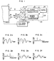
- a vibration sensor 12 which produces an analog signal 14 an amplitude of which varies with time (hereinafter referred to as an analog time-domain signal).
- the analog time-domain signal 14 from the vibration sensor is converted by an analog-to-digital (A/D) converter 16 to a digital signal 18 an amplitude of which varies with.time (hereinafter referred to as a digital time-domain signal).
- the digital time-domain signal 18 is then subject to Fourier transformation by a Fourier transformation circuit 20 to a digital signal 22 an amplitude of which varies with frequencies (hereinafter referred to. as a digital frequency-domain signal).
- a control circuit 24 determines the amplitudes and the phases of the frequency components such that the amplitudes of the frequency components are reduced, and the resulting signals are applied to an inverse Fourier transformation circuit 28 as a vibration reducing digital frequency-domain signal 26.
- the digital frequency-domain signal 26 is subject to inverse Fourier transformation by the inverse Fourier transformation circuit 28 to a digital time-domain signal 30, which is converted by a digital-to-analog (D/A) converter 32 to an analog time-domain signal 34, which in turn is amplified by a power amplifier 36 an output of which is supplied to a vibration applying device 38 to actuate it.
- D/A digital-to-analog
- the vibration applying device 38 generates vibrations for reducing the amplitudes of the frequency components of the vibrations generated by the electrical apparatus 10. The thus generated vibrations are then applied to. the electrical apparatus 10 to reduce the vibrations of the electrical apparatus 10.
- the control circuit 24 changes the amplitude and the phase of the vibration reducing digital frequency-domain signal 26 such that the vibrations of the electrical apparatus 10 are minimized.
- the sampling operations of the A/D converter 16 and the D/A converter 32 are controlled by a synchronizing signal 42 generated by a synchronizing signal generator 40.
- the electrical apparatus 10 is a transformer, for example, the frequency of the vibration is an integer multiple of a power supply frequency. Accordingly, the synchronizing signal generator 40 receives the power supply frequency of the electrical apparatus 10 to generate the synchronizing signal of a frequency which is an integer multiple of the power supply frequency.
- Figs. 2a to. 2f show waveforms of signals at various points in the vibrati.on reducing apparatus shown in Fig. 1, that is, the waveforms of the analog time-domain signal 14, the digital time-domain signal 18, the digital frequency-domain signal 22, the digital frequency-domain signal 26, the digital time-domain signal 30 and the analog time-domain signal 34 respectively.
- the control circuit 24 responds to the change in the amplitudes of the frequency components of the digital frequency-domain signal 22 (Fig. 2c) applied thereto to vary the amplitude and the phase of the digital frequency signal 26 produced thereby such that the amplitude of the signal 22 is minimized.
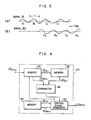
- Fig. 3 shows a relationship between the digital time-domain signal 18 (Fig. 2b) produced by the A/D converter 16, that is, the input signal to the Fourier transformation circuit 20 and the digital time-domain signal 30 (Fig. 2e) applied to the D/A converter 32, that is, the output signal from the inverse Fourier transformation circuit 28.
- the 2 n (where n is a positive integer) input signals 18 (Fig. 2b) per time interval T are sampled and data in a section A1 are processed within the time interval T of the next sequential section B 1 by the Fourier transformation circuit 20, the control circuit 24 and the inverse Fourier transformation circuit 28 and the output signal 30 (Fig. 2e) is produced in an output signal time section A 2 which corresponds to the next sequential section C1 of the section Bl.
- the data in the sections B 1 , C 1 , D 1 , ... for the input signal 18 are processed to produce the output signal 30 in the sections B 2 , C 2 , D 2 , ..., respectively.
- the signal are applied to and produced from the Fourier transformation circuit 20, the control circuit 24 and the inverse Fourier transformation circuit 28 in a continuous manner without no gap of data.
- the data in one T-time period is called a frame.
- a T-processing time is allowed to one frame of data and the Fourier transformation, the conversion to the vibration reducing digital frequency-domain signal, the averaging process and the inverse Fourier-transformation are carried out within the T-processing time.
- the digital time-domain signal 18 produced by the A/D converter 16 is fed serially in time as shown in Fig. 3 and applied to the Fourier transformation circuit 20. It is processed in each of the time sections in the following manner.
- the digital time-domain signal portion 18 t1 which is A/D-converted in the time section t 1 is processed in the next time section t 2 as follows.
- the signal portion 18 t1 is Fourier-transformed by the Fourier transformation circuit 20 to produce a digital frequency-domain signal portion 22 t1 , that is, a Fourier-transformed data of the time section t 1 , which is applied to a first memory 44 so as to be stored therein and also to be applied to a comparator 46.
- the comparator 46 compares the amplitude and the phase of the Fourier-transformed data with those of a Fourier-transformed data of the immediately preceding time section which is stored in a second memory 48 and is to be supplied therefrom.
- the Fourier-transformed data 22 tl of the first time section t l the Fourier-transformed data of the preceding time section to be compared with has not been stored in the second memory 48 and hence no compare takes place.
- the comparator 46 sends a signal representing that the applied data is only the Fourier-transformed data of the time section tl to a control signal generator 50, which responds to that signal from the comparator 46 to read out an initial control signal previously stored in a third memory 52 as a digital frequency-domain signal portion 26 t1 , which is then applied to the inverse Fourier transformation circuit 28 and also stored in the third memory 52 as a control signal produced correspondingly to the time section t 1 .
- the inverse Fourier transformation circuit 28 inverse-Fourier- transforms the digital frequency-domain signal portion 26 t1 to produce a digital time-domain signal portion 30 t1 .
- the time section t 2 extends from the start of the application of the digital time-domain signal portion 18 tl to the Fourier transformation circuit 20 to the start of the application of the digital time-domain signal portion 30 ti to the D/A converter 32. Within the time section t 2 , the digital frequency-domain signal portion 22 t1 is also transferred from the first memory 44 to the second memory 48.
- the digital frequency-domain signal portion 22 t2 derived by Fourier-transforming by the Fourier transformation circuit 20 the digital time-domain signal portion 18 t2 which was converted by the A/D.converter 16 in the time section t 2 is supplied to the first memory 44 so as to be stored therein and also to be applied to the comparator 46 as a current Fourier-transformed data.
- the Fourier-transformed data of the previous time section stored in the second memory 48 is also applied to. the comparator 46, which compares the amplitudes and the phases of those two data.
- a signal representing the result is sent to the control signal generator 50, which, based on that signal, changes the amplitude and the phase of the control signal portion 26tl of the previous time section which has been stored in the third memory 52 and is to be supplied therefrom by predetermined small magnitudes in the direction of decreasing the vibration, and the resulting control signal portion is sent to the inverse Fourier transformation circuit 28 as a current control signal portion 26 t2 and it is also stored in the third memory 52.
- the digital frequency-domain signal portion 26 t2 is inverse-Fourier-transformed to produce a digital time-domain signal portion 30 t2 .
- the signal processing thus far is carried out in the time section t 3 .
- the Fourier-transformed data 22 t2 stored in the first memory 44 is sent to the second memory 48 and stored therein.
- the signal processing thus far described may be described in a general form as follows. If it is determined that the vibration is increasing (or decreasing) in the time section t m+1 as a result of the increase of the amplitude (and/or phase) of the control signal 26t m-1 in the time section t m to produce the control signal 26 t m , the amplitude (and/or phase) of the previous control signal 26t m is decreased (or increased) to produce the current control signal 26t m+1 ⁇ Conversely, if it is determined that the vibration is increasing (or decreasing) in the time section t m+1 , as a result of the decrease of the amplitude (and/or phase) of the previous control signal 26t m-1 in the time section t m to produce the control signal 26t ml the amplitude (and/or phase) of the previous control signal 26t m is increased (or decreased).
- control signal 26t n is produced in each time section and the contents of the second and third memories are updated each time.
- the digital frequency-domain signal 22 shown in Fig. 2c includes no leakage phenomenon which would appear when the integer multiple of the signal does not coincide with the sampling frequency.
- a number of frequency components would appear in Fig. 2c in spite of the fact that only one frequency component is present and hence reading accuracy of the amplitude and phase would be lowered.
- the reading accuracy of the amplitude and phase is improved.
- the frequency components which are not related to the power supply frequency that is, external noises are substantially reduced. so that the control accuracy is further enhanced.
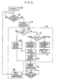
- a block 60 encircled by a chain line, that is, the Fourier transformation circuit 20, the control circuit 24 and the inverse Fourier transformation circuit 28 may be constituted by a microcomputer. The operation thereof is illustrated in a flow chart of Fig. 5.
- the system is initialized (step 100.)., and the output or the digital time-domain signal 18 of the A/D converter 16 is read in (step 102).
- the read-in data 18 is Fourier-transformed to the digital frequency-domain signal 22 (step 104) which is examined to determine if it is the data of the first time section (step 106). If the decision is "YES", the previously stored initial control signal is produced as the vibration reducing digital frequency-domain signal 26 (step 108).
- the digital frequency-domain signal 22 is compared with the digital frequency-domain signal 22 which was read, Fourier-transformed and stored in the previous time section to determine the necessity of adjustment of the amplitude/phase of the control signal 26 which as produced and stored in the previous time section (step 110). After the amplitude/ phase are adjusted (step 112 and 114), a new control signal 26 is produced (step 116). The control signal 26 produced at the step 108 or 116 is inverse-Fourier-transformed to the digital time-domain signal 30 (step 118) and read into the D/A converter 32 (step 120). After the read-in, an instruction to generate the next output data is issued (step 122).
- the vibration sensor 12 and the vibration applying device 38 shown in Fig. 1 are substituted by a'noise sensor (microphone) 70 and a speaker 72 shown in Fig. 6 so that a noise reducing sound wave generated by the speaker 72 interferes with the noise to reduce it.
- the vibrati.on sensor 12 shown in Fig. 1 may be left and otly the vibration applying device 38 may be substituted by the speaker 72 .to. reduce the noise. Conversely, the vibration applying device 38 shown in Fig. 1 may be left and only the vibration sensor 12 may be substituted by the noise sensor (microphone) 70 to reduce the vibration.
- the vibrations and/or the noises can be more effectively reduced.
- the frequency of vibration is not always equal to an integer multiple of the power supply frequency.
- the power supply frequency is not used as the input to the synchronizing signal generator 40 but, as shown in Fig. 7, the signal sensed by a vibration sensor 74 is passed through a frequency filter 76 to separate the frequency.
- a noise sensor (microphone) 78 may be used instead of the vibration sensor 74. While the vibration sensor 74 or the noise sensor 78 is shown to be separately arranged from the sensor 12 or 38 shown in Fig. 1, it should be understood that the sensor 74 or 78 may not be separately arranged but the output of the sensor 12 or 38 may be applied to the frequency filter 76.
Abstract
Description
- The present invention relates to a device for reducing vibrations and/or noises resulting from the vibrations of an electrical apparatus such as stationary induction apparatus e.g. a reactor or such as a rotary machine e.g. a motor.
- Since electricity is used in those apparatus as energy sources, vibrations and noises are generated due to electromagnetic forces. In the past, in order to prevent the vibrations and the noises a dumper material was attached to the surface of the electrical apparatus or the electrical apparatus was surrounded by a sound barrier wall. However, those methods had limitations in the amount of reduction of the vibrations and noises. In addition, those methods have increased the overall size of the apparatus.
- It has been proposed to reduce the vibrations and/or noises due to the vibrations by applying thereto other vibrations and/or sound waves which are of substantially opposite phase to the vibrations and/or the resulting noises of the electrical apparatus. (For example, see Japanese Patent Publication No. 417/1958.) Since the vibrations sound waves for reducing vibrations/ noises were generated by analog means in the prior art vibration/noise reducing system, band pass filters, phase shifters and amplitude controllers were required, one set for each frequency component of the vibrations and/or the noises to be reduced. As a result, a complicated circuit configuration was required to attain high accuracy and the respective sets of phase shifters and amplitude controllers had to be adjusted manually with very troublesome work. In addition, since the analog band pass filters did not provide high resolution for the frequency, control accuracy was poor. Consequently, this method has not been put into practice.
- It is an object of the present invention to provide a vibration/sound reducing device for an electrical apparatus which overcomes the problems encountered in the prior art systems, which is simple in circuit configuration, which is easy to adjust and which may control with high accuracy to effectively reduce the vibrations and/or the noises resulting from the vibrations.
- In order to attain the above object,. according to the present invention, there is provided a device for reducing vibrations generated in an electrical apparatus or noises resulting from said vibrations, comprising a sensor for sensing the vibrations or the resulting noises to produce a first analog time-domain signal, an analog-to-digital converter for converting the first analog time-domain signal to a corresponding first digital time-domain signal, a Fourier transformation circuit for Fourier transforming the digital time-domain signal to a corresponding first digital frequency-domain signal, a control circuit for producing a second digital time-domain signal based on the first digital frequency-domain signal, an inverse Fourier transformation circuit for inverse Fourier transforming the second digital frequency-domain signal to a corresponding second digital time-domain signal, a digital-to-analog converter for converting the second digital time-domain signal to a corresponding second analog time domain signal, an amplifier for amplifying the second analog time-domain signal, and a vibration applying device actuated by the amplified second analog time-domain signal to apply vibration-reducing vibrations to. the electrical apparatus or a sound speaker for generating noise reducing sound waves.
- Other objects and features of the present invention will be apparent from the preferred embodiments of the present invention taken in conjunction with the accompanying drawings, in which:
- Fig. 1 shows a block diagram of one embodiment of the present invention;
- Figs. 2a to 2f show signal waveforms at various points in the embodiment of Fig. 1;
- Fig. 3 illustrates input and output signals of a Fourier transformation circuit;
- Fig. 4 shows a block diagram of another embodiment of the present invention;
- Fig. 5 shows a flow chart of a further embodiment of the present invention; and
- . Figs. 6 to 8 show block diagrams of a still further embodiment of the present invention.
- Referring now to Fig. 1, an embodiment of the present invention is explained. In Fig. 1, vibrations generated by an
electrical apparatus 10 such as a transformer is sensed by avibration sensor 12 which produces ananalog signal 14 an amplitude of which varies with time (hereinafter referred to as an analog time-domain signal). The analog time-domain signal 14 from the vibration sensor is converted by an analog-to-digital (A/D)converter 16 to adigital signal 18 an amplitude of which varies with.time (hereinafter referred to as a digital time-domain signal). The digital time-domain signal 18 is then subject to Fourier transformation by a Fouriertransformation circuit 20 to adigital signal 22 an amplitude of which varies with frequencies (hereinafter referred to. as a digital frequency-domain signal). Since the digital frequency-domain signal 22 represents amplitudes and phases-of frequency components of the vibrations generated in theelectrical apparatus 10, acontrol circuit 24 determines the amplitudes and the phases of the frequency components such that the amplitudes of the frequency components are reduced, and the resulting signals are applied to an inverse Fouriertransformation circuit 28 as a vibration reducing digital frequency-domain signal 26. The digital frequency-domain signal 26 is subject to inverse Fourier transformation by the inverse Fouriertransformation circuit 28 to a digital time-domain signal 30, which is converted by a digital-to-analog (D/A)converter 32 to an analog time-domain signal 34, which in turn is amplified by apower amplifier 36 an output of which is supplied to avibration applying device 38 to actuate it. In response to. the actuation by the amplified analog time-domain signal, thevibration applying device 38 generates vibrations for reducing the amplitudes of the frequency components of the vibrations generated by theelectrical apparatus 10. The thus generated vibrations are then applied to. theelectrical apparatus 10 to reduce the vibrations of theelectrical apparatus 10. Thecontrol circuit 24 changes the amplitude and the phase of the vibration reducing digital frequency-domain signal 26 such that the vibrations of theelectrical apparatus 10 are minimized. The sampling operations of the A/D converter 16 and the D/A converter 32 are controlled by a synchronizing signal 42 generated by a synchronizingsignal generator 40. In the case where theelectrical apparatus 10 is a transformer, for example, the frequency of the vibration is an integer multiple of a power supply frequency. Accordingly, the synchronizingsignal generator 40 receives the power supply frequency of theelectrical apparatus 10 to generate the synchronizing signal of a frequency which is an integer multiple of the power supply frequency. - Figs. 2a to. 2f show waveforms of signals at various points in the vibrati.on reducing apparatus shown in Fig. 1, that is, the waveforms of the analog time-
domain signal 14, the digital time-domain signal 18, the digital frequency-domain signal 22, the digital frequency-domain signal 26, the digital time-domain signal 30 and the analog time-domain signal 34 respectively. Thecontrol circuit 24 responds to the change in the amplitudes of the frequency components of the digital frequency-domain signal 22 (Fig. 2c) applied thereto to vary the amplitude and the phase of thedigital frequency signal 26 produced thereby such that the amplitude of thesignal 22 is minimized. - Fig. 3 shows a relationship between the digital time-domain signal 18 (Fig. 2b) produced by the A/
D converter 16, that is, the input signal to the Fouriertransformation circuit 20 and the digital time-domain signal 30 (Fig. 2e) applied to the D/A converter 32, that is, the output signal from the inverseFourier transformation circuit 28. The 2n (where n is a positive integer) input signals 18 (Fig. 2b) per time interval T are sampled and data in a section A1 are processed within the time interval T of the next sequential section B1 by theFourier transformation circuit 20, thecontrol circuit 24 and the inverseFourier transformation circuit 28 and the output signal 30 (Fig. 2e) is produced in an output signal time section A2 which corresponds to the next sequential section C1 of the section Bl. Similarly, the data in the sections B1, C1, D1, ... for the input signal 18 (Fig. 2b) are processed to produce theoutput signal 30 in the sections B2, C2, D2, ..., respectively. The signal are applied to and produced from theFourier transformation circuit 20, thecontrol circuit 24 and the inverse Fouriertransformation circuit 28 in a continuous manner without no gap of data. The data in one T-time period is called a frame. A T-processing time is allowed to one frame of data and the Fourier transformation, the conversion to the vibration reducing digital frequency-domain signal, the averaging process and the inverse Fourier-transformation are carried out within the T-processing time. - Since frequency resolution Δf of the Fourier transformation is equal to 1/T, the resolution Δf is equal to 1 Hz when T is equal to one second. It has been very difficult to attain such high resolution by the conventional analog frequency filter.
- The present embodiment presents the following advantages:
- (1) Since only.one common set of A/D converter, Foxrier transformation circuit, control circuit, inverse Fourier transformation circuit and D/A converter is needed to the respective frequency components of the vibrations to be reduced, the circuit configuration of the apparatus is very much simplified and a control range thereof is expanded. As a result, a stable control for reducing the vibrations is attained and the adjustment work is facilitated.
- (2) Since high frequency resolution is attained, control accuracy for reducing the vibrations is enhanced.
- (3) Since the sampling operations are in synchronism with the vibration frequency, calculation accuracy for the amplitude and the phase is enhanced and electrical noises are eliminated by the averaging process so that the control accuracy for reducing vibrations is further enhanced.
- Fig. 4 shows a block diagram of the
control circuit 24. Referring to Fig. 4, the operation of thecontrol circuit 24 is explained in detail. In the following description, suffixes tn (n = 1, 2, ..., m, m+1, ...) of the reference numerals for the signals represent respective time sections. - The digital time-
domain signal 18 produced by the A/D converter 16 is fed serially in time as shown in Fig. 3 and applied to the Fouriertransformation circuit 20. It is processed in each of the time sections in the following manner. The digital time-domain signal portion 18t1 which is A/D-converted in the time section t1 is processed in the next time section t2 as follows. Thesignal portion 18t1 is Fourier-transformed by theFourier transformation circuit 20 to produce a digital frequency-domain signal portion 22t1, that is, a Fourier-transformed data of the time section t1, which is applied to afirst memory 44 so as to be stored therein and also to be applied to acomparator 46. Thecomparator 46 compares the amplitude and the phase of the Fourier-transformed data with those of a Fourier-transformed data of the immediately preceding time section which is stored in asecond memory 48 and is to be supplied therefrom. For the Fourier-transformeddata 22tl of the first time section tl, the Fourier-transformed data of the preceding time section to be compared with has not been stored in thesecond memory 48 and hence no compare takes place. Thus, thecomparator 46 sends a signal representing that the applied data is only the Fourier-transformed data of the time section tl to acontrol signal generator 50, which responds to that signal from thecomparator 46 to read out an initial control signal previously stored in athird memory 52 as a digital frequency-domain signal portion 26t1, which is then applied to the inverseFourier transformation circuit 28 and also stored in thethird memory 52 as a control signal produced correspondingly to the time section t1. The inverseFourier transformation circuit 28 inverse-Fourier- transforms the digital frequency-domain signal portion 26t1 to produce a digital time-domain signal portion 30t1. The time section t2 extends from the start of the application of the digital time-domain signal portion 18tl to theFourier transformation circuit 20 to the start of the application of the digital time-domain signal portion 30ti to the D/A converter 32. Within the time section t2, the digital frequency-domain signal portion 22t1 is also transferred from thefirst memory 44 to thesecond memory 48. In the next time section t3, the digital frequency-domain signal portion 22t2 derived by Fourier-transforming by theFourier transformation circuit 20 the digital time-domain signal portion 18t2 which was converted by the A/D.converter 16 in the time section t2 is supplied to thefirst memory 44 so as to be stored therein and also to be applied to thecomparator 46 as a current Fourier-transformed data. The Fourier-transformed data of the previous time section stored in thesecond memory 48 is also applied to. thecomparator 46, which compares the amplitudes and the phases of those two data. If the comparison result indicates the increase (or decrease) of vibration, a signal representing the result is sent to thecontrol signal generator 50, which, based on that signal, changes the amplitude and the phase of the control signal portion 26tl of the previous time section which has been stored in thethird memory 52 and is to be supplied therefrom by predetermined small magnitudes in the direction of decreasing the vibration, and the resulting control signal portion is sent to the inverseFourier transformation circuit 28 as a currentcontrol signal portion 26t2 and it is also stored in thethird memory 52. The digital frequency-domain signal portion 26t2 is inverse-Fourier-transformed to produce a digital time-domain signal portion 30t2. The signal processing thus far is carried out in the time section t3. In the time section t3, the Fourier-transformeddata 22t2 stored in thefirst memory 44 is sent to thesecond memory 48 and stored therein. - The signal processing thus far described may be described in a general form as follows. If it is determined that the vibration is increasing (or decreasing) in the time section tm+1 as a result of the increase of the amplitude (and/or phase) of the control signal 26tm-1 in the time section tm to produce the control signal 26 tm, the amplitude (and/or phase) of the previous control signal 26tm is decreased (or increased) to produce the current control signal 26tm+1· Conversely, if it is determined that the vibration is increasing (or decreasing) in the time section tm+1, as a result of the decrease of the amplitude (and/or phase) of the previous control signal 26t m-1 in the time section tm to produce the control signal 26tml the amplitude (and/or phase) of the previous control signal 26tm is increased (or decreased).
- In this manner, the control signal 26tn is produced in each time section and the contents of the second and third memories are updated each time.
- In the present embodiment, since the A/
D converter 16 and the D/A converter 32 effect their sampling operation in response to the synchronizing signal which has the frequency equal to the integer multiple of the power supply frequency and is generated by the synchronizingsignal generator 40, the digital frequency-domain signal 22 shown in Fig. 2c includes no leakage phenomenon which would appear when the integer multiple of the signal does not coincide with the sampling frequency. When such leakage phenomenon occurs, a number of frequency components would appear in Fig. 2c in spite of the fact that only one frequency component is present and hence reading accuracy of the amplitude and phase would be lowered. In the present embodiment, since no such leakage phenomena occurs, the reading accuracy of the amplitude and phase is improved. In addition, by averaging the signals shown in Figs. 2b and 2c, the frequency components which are not related to the power supply frequency, that is, external noises are substantially reduced. so that the control accuracy is further enhanced. - In the embodiment shown in Fig. 1, a
block 60 encircled by a chain line, that is, theFourier transformation circuit 20, thecontrol circuit 24 and the inverseFourier transformation circuit 28 may be constituted by a microcomputer. The operation thereof is illustrated in a flow chart of Fig. 5. - First, the system is initialized (step 100.)., and the output or the digital time-
domain signal 18 of the A/D converter 16 is read in (step 102). The read-indata 18 is Fourier-transformed to the digital frequency-domain signal 22 (step 104) which is examined to determine if it is the data of the first time section (step 106). If the decision is "YES", the previously stored initial control signal is produced as the vibration reducing digital frequency-domain signal 26 (step 108). If the decision at thestep 106 is "NO", the digital frequency-domain signal 22 is compared with the digital frequency-domain signal 22 which was read, Fourier-transformed and stored in the previous time section to determine the necessity of adjustment of the amplitude/phase of thecontrol signal 26 which as produced and stored in the previous time section (step 110). After the amplitude/ phase are adjusted (step 112 and 114), anew control signal 26 is produced (step 116). Thecontrol signal 26 produced at thestep 108 or 116 is inverse-Fourier-transformed to the digital time-domain signal 30 (step 118) and read into the D/A converter 32 (step 120). After the read-in, an instruction to generate the next output data is issued (step 122). - While the present invention is intended to reduce the vibrations per se, the noises resulting from the vibrations may be reduced. In that case, the
vibration sensor 12 and thevibration applying device 38 shown in Fig. 1 are substituted by a'noise sensor (microphone) 70 and aspeaker 72 shown in Fig. 6 so that a noise reducing sound wave generated by thespeaker 72 interferes with the noise to reduce it. - Although not shown, the vibrati.on
sensor 12 shown in Fig. 1 may be left and otly thevibration applying device 38 may be substituted by thespeaker 72 .to. reduce the noise. Conversely, thevibration applying device 38 shown in Fig. 1 may be left and only thevibration sensor 12 may be substituted by the noise sensor (microphone) 70 to reduce the vibration. - By aranging a number of
vibration applying devices 38 and/or thespeaker 72 instead of one as shown in the illustrated embodiment, the vibrations and/or the noises can be more effectively reduced. - When the
electrical apparatus 10 is a motor or the like, the frequency of vibration is not always equal to an integer multiple of the power supply frequency. In this case, the power supply frequency is not used as the input to the synchronizingsignal generator 40 but, as shown in Fig. 7, the signal sensed by a vibration sensor 74 is passed through afrequency filter 76 to separate the frequency. When the noise is to be reduced, a noise sensor (microphone) 78 may be used instead of the vibration sensor 74. While the vibration sensor 74 or thenoise sensor 78 is shown to be separately arranged from thesensor sensor 74 or 78 may not be separately arranged but the output of thesensor frequency filter 76.
Claims (6)
Applications Claiming Priority (2)
| Application Number | Priority Date | Filing Date | Title |
|---|---|---|---|
| JP89979/80 | 1980-07-03 | ||
| JP8997980A JPS5717027A (en) | 1980-07-03 | 1980-07-03 | Vibration reducing device of electric machinery |
Publications (2)
| Publication Number | Publication Date |
|---|---|
| EP0043565A1 true EP0043565A1 (en) | 1982-01-13 |
| EP0043565B1 EP0043565B1 (en) | 1985-01-23 |
Family
ID=13985779
Family Applications (1)
| Application Number | Title | Priority Date | Filing Date |
|---|---|---|---|
| EP81105155A Expired EP0043565B1 (en) | 1980-07-03 | 1981-07-02 | Vibration/noise reduction device for electrical apparatus |
Country Status (4)
| Country | Link |
|---|---|
| US (1) | US4435751A (en) |
| EP (1) | EP0043565B1 (en) |
| JP (1) | JPS5717027A (en) |
| DE (1) | DE3168464D1 (en) |
Cited By (23)
| Publication number | Priority date | Publication date | Assignee | Title |
|---|---|---|---|---|
| EP0071947A2 (en) * | 1981-08-11 | 1983-02-16 | Hitachi, Ltd. | Method and apparatus for reducing vibrations of stationary induction apparatus |
| WO1983001525A1 (en) * | 1981-10-21 | 1983-04-28 | Chaplin, George, Brian, Barrie | Improved method and apparatus for cancelling vibrations |
| FR2531023A1 (en) * | 1982-08-02 | 1984-02-03 | Peugeot | Noise attenuation device in the passenger compartment of an automobile vehicle. |
| FR2533100A1 (en) * | 1982-09-09 | 1984-03-16 | Sintra Alcatel Sa | METHOD AND APPARATUS FOR MITIGATION OF NOISE NOISE |
| FR2533057A1 (en) * | 1982-09-09 | 1984-03-16 | Sintra Alcatel Sa | METHOD AND DEVICES FOR ELIMINATING ACOUSTIC OR MECHANICAL VIBRATION EFFECTS |
| EP0103252A2 (en) * | 1982-09-11 | 1984-03-21 | BASF Aktiengesellschaft | Aryloxyalkyl amines, process for their preparation and their use in combating unwanted plant growth |
| GB2149273A (en) * | 1983-11-02 | 1985-06-05 | British Gas Corp | Active control of flame noise |
| GB2191063A (en) * | 1986-05-01 | 1987-12-02 | Plessey Co Plc | Active noise suppression |
| US4740750A (en) * | 1982-08-28 | 1988-04-26 | Tokyo Shibaura Denki Kabushiki Kaisha | Reception signal processing apparatus in nuclear magnetic resonance diagnostic apparatus |
| US4760295A (en) * | 1985-04-17 | 1988-07-26 | Geoquip Security Systems Ltd. | Vibration-sensitive transducer |
| EP0361968A2 (en) * | 1988-09-30 | 1990-04-04 | Kabushiki Kaisha Toshiba | Noise cancellor |
| WO1990013108A1 (en) * | 1989-04-25 | 1990-11-01 | Active Noise And Vibration Technologies Inc. | Active sound and/or vibration control |
| GB2240199A (en) * | 1989-12-18 | 1991-07-24 | Toshiba Kk | Low noise refrigerator |
| GB2240198A (en) * | 1989-12-18 | 1991-07-24 | Toshiba Kk | Low noise refrigerator |
| GB2271908A (en) * | 1992-10-21 | 1994-04-27 | Lotus Car | Adaptive control for a noise cancelling system |
| GB2271909A (en) * | 1992-10-21 | 1994-04-27 | Lotus Car | Adaptive vibration control system |
| EP0615224A2 (en) * | 1993-03-09 | 1994-09-14 | Fujitsu Limited | A method of determining the sound transfer characteristic of an active noise control system |
| EP0693747A2 (en) | 1994-07-18 | 1996-01-24 | Gec-Marconi Limited | An apparatus for cancelling vibrations |
| DE4432532A1 (en) * | 1994-09-13 | 1996-03-14 | Stn Atlas Elektronik Gmbh | Process for the elimination of structure-borne noise |
| US5838802A (en) * | 1994-07-18 | 1998-11-17 | Gec-Marconi Limited | Apparatus for cancelling vibrations |
| CN106469605A (en) * | 2016-11-21 | 2017-03-01 | 国网山东省电力公司东营供电公司 | A kind of system and method shaking noise for reducing transformator |
| CN106596130A (en) * | 2016-12-20 | 2017-04-26 | 江苏金坛大迈汽车工程研究院有限公司 | Finished automobile noise vibration source detection method and vibration source detection device using same |
| CN108140378A (en) * | 2015-10-16 | 2018-06-08 | 哈曼贝克自动系统股份有限公司 | The noise and vibration-sensing of extension |
Families Citing this family (40)
| Publication number | Priority date | Publication date | Assignee | Title |
|---|---|---|---|---|
| JPS60252835A (en) * | 1984-05-28 | 1985-12-13 | Mitsubishi Motors Corp | Car body vibration reducing device |
| US4941185A (en) * | 1985-03-18 | 1990-07-10 | Crosfield Electronics | Image processing |
| JPS61195955U (en) * | 1985-05-29 | 1986-12-06 | ||
| US4744242A (en) * | 1986-09-16 | 1988-05-17 | The Boeing Company | Method for monitoring cutting tool wear during a machining operation |
| US4937758A (en) * | 1987-09-04 | 1990-06-26 | Technology Integration And Development Group, Inc. | Method and apparatus for reducing vibration over the full operating range of a rotor and a host device |
| US4947435A (en) * | 1988-03-25 | 1990-08-07 | Active Noise & Vibration Tech | Method of transfer function generation and active noise cancellation in a vibrating system |
| US5202900A (en) * | 1989-08-07 | 1993-04-13 | Motorola, Inc. | Spectrally efficient digital FM modulated transmitter |
| US5068874A (en) * | 1989-08-07 | 1991-11-26 | Motorola, Inc. | Spectrally efficient digital fm modulation system |
| US5233540A (en) * | 1990-08-30 | 1993-08-03 | The Boeing Company | Method and apparatus for actively reducing repetitive vibrations |
| US5245552A (en) * | 1990-10-31 | 1993-09-14 | The Boeing Company | Method and apparatus for actively reducing multiple-source repetitive vibrations |
| US5243512A (en) * | 1991-05-20 | 1993-09-07 | Westinghouse Electric Corp. | Method and apparatus for minimizing vibration |
| US5629872A (en) * | 1992-01-29 | 1997-05-13 | Arch Development Corporation | System for monitoring an industrial process and determining sensor status |
| US5410492A (en) * | 1992-01-29 | 1995-04-25 | Arch Development Corporation | Processing data base information having nonwhite noise |
| US5459675A (en) * | 1992-01-29 | 1995-10-17 | Arch Development Corporation | System for monitoring an industrial process and determining sensor status |
| JP3276214B2 (en) * | 1992-08-31 | 2002-04-22 | マツダ株式会社 | Vehicle vibration reduction device |
| US5416847A (en) * | 1993-02-12 | 1995-05-16 | The Walt Disney Company | Multi-band, digital audio noise filter |
| US5327242A (en) * | 1993-03-18 | 1994-07-05 | Matsushita Electric Corporation Of America | Video noise reduction apparatus and method using three dimensional discrete cosine transforms and noise measurement |
| US5539831A (en) * | 1993-08-16 | 1996-07-23 | The University Of Mississippi | Active noise control stethoscope |
| WO1995007530A1 (en) * | 1993-09-09 | 1995-03-16 | Noise Cancellation Technologies, Inc. | Global quieting system for stationary induction apparatus |
| JP3572486B2 (en) * | 1994-03-25 | 2004-10-06 | 本田技研工業株式会社 | Vibration noise control device |
| US5586066A (en) * | 1994-06-08 | 1996-12-17 | Arch Development Corporation | Surveillance of industrial processes with correlated parameters |
| US5745384A (en) * | 1995-07-27 | 1998-04-28 | Lucent Technologies, Inc. | System and method for detecting a signal in a noisy environment |
| US5761090A (en) * | 1995-10-10 | 1998-06-02 | The University Of Chicago | Expert system for testing industrial processes and determining sensor status |
| US6654467B1 (en) * | 1997-05-07 | 2003-11-25 | Stanley J. York | Active noise cancellation apparatus and method |
| US6478110B1 (en) | 2000-03-13 | 2002-11-12 | Graham P. Eatwell | Vibration excited sound absorber |
| US6526356B1 (en) * | 2001-06-19 | 2003-02-25 | The Aerospace Corporation | Rocket engine gear defect monitoring method |
| US8256590B2 (en) * | 2007-05-24 | 2012-09-04 | Okuma Corporation | Vibration suppressing device and vibration suppressing method for machine tool |
| US8229598B2 (en) * | 2007-09-06 | 2012-07-24 | Okuma Corporation | Vibration suppressing device for machine tool |
| US8014903B2 (en) * | 2007-10-25 | 2011-09-06 | Okuma Corporation | Method for suppressing vibration and device therefor |
| JP5522038B2 (en) * | 2008-05-14 | 2014-06-18 | シンフォニアテクノロジー株式会社 | Vibration control device and vehicle |
| JP5160980B2 (en) * | 2008-07-08 | 2013-03-13 | オークマ株式会社 | Vibration suppression method and apparatus |
| US8005574B2 (en) * | 2008-07-08 | 2011-08-23 | Okuma Corporation | Vibration suppressing method and device |
| JP4643701B2 (en) * | 2008-10-24 | 2011-03-02 | レノボ・シンガポール・プライベート・リミテッド | Noise-eliminating power supply |
| JP5234772B2 (en) * | 2008-10-28 | 2013-07-10 | オークマ株式会社 | Vibration suppression method and apparatus for machine tool |
| JP5368232B2 (en) * | 2009-09-24 | 2013-12-18 | オークマ株式会社 | Vibration suppression device |
| JP2011141667A (en) * | 2010-01-06 | 2011-07-21 | Sony Ericsson Mobilecommunications Japan Inc | Terminal equipment and control method of the same |
| KR101244382B1 (en) | 2011-03-21 | 2013-03-18 | 최훈석 | Apparatus for controlling a carrier |
| CN104767344B (en) * | 2015-04-14 | 2017-04-19 | 上海电机系统节能工程技术研究中心有限公司 | Method for eliminating vibration of PWM powered brushless direct current motor through frequency calculation |
| JP6445921B2 (en) * | 2015-04-21 | 2018-12-26 | 任天堂株式会社 | Vibration signal generation program, vibration signal generation system, vibration signal generation device, vibration signal generation method, and data output program |
| US10720139B2 (en) * | 2017-02-06 | 2020-07-21 | Silencer Devices, LLC. | Noise cancellation using segmented, frequency-dependent phase cancellation |
Citations (3)
| Publication number | Priority date | Publication date | Assignee | Title |
|---|---|---|---|---|
| US4066842A (en) * | 1977-04-27 | 1978-01-03 | Bell Telephone Laboratories, Incorporated | Method and apparatus for cancelling room reverberation and noise pickup |
| US4122303A (en) * | 1976-12-10 | 1978-10-24 | Sound Attenuators Limited | Improvements in and relating to active sound attenuation |
| WO1981000638A1 (en) * | 1979-08-16 | 1981-03-05 | Sound Attenuators Ltd | A method of reducing the adaption time in the cancellation of repetitive vibration |
Family Cites Families (1)
| Publication number | Priority date | Publication date | Assignee | Title |
|---|---|---|---|---|
| JPS5218873A (en) * | 1975-08-02 | 1977-02-12 | Agency Of Ind Science & Technol | Process for multiplying microorganisms |
-
1980
- 1980-07-03 JP JP8997980A patent/JPS5717027A/en active Granted
-
1981
- 1981-07-02 DE DE8181105155T patent/DE3168464D1/en not_active Expired
- 1981-07-02 EP EP81105155A patent/EP0043565B1/en not_active Expired
- 1981-07-02 US US06/279,814 patent/US4435751A/en not_active Expired - Fee Related
Patent Citations (3)
| Publication number | Priority date | Publication date | Assignee | Title |
|---|---|---|---|---|
| US4122303A (en) * | 1976-12-10 | 1978-10-24 | Sound Attenuators Limited | Improvements in and relating to active sound attenuation |
| US4066842A (en) * | 1977-04-27 | 1978-01-03 | Bell Telephone Laboratories, Incorporated | Method and apparatus for cancelling room reverberation and noise pickup |
| WO1981000638A1 (en) * | 1979-08-16 | 1981-03-05 | Sound Attenuators Ltd | A method of reducing the adaption time in the cancellation of repetitive vibration |
Cited By (41)
| Publication number | Priority date | Publication date | Assignee | Title |
|---|---|---|---|---|
| EP0071947A3 (en) * | 1981-08-11 | 1984-03-07 | Hitachi, Ltd. | Method and apparatus for reducing vibrations of stationary induction apparatus |
| EP0071947A2 (en) * | 1981-08-11 | 1983-02-16 | Hitachi, Ltd. | Method and apparatus for reducing vibrations of stationary induction apparatus |
| US4490841A (en) * | 1981-10-21 | 1984-12-25 | Sound Attenuators Limited | Method and apparatus for cancelling vibrations |
| WO1983001525A1 (en) * | 1981-10-21 | 1983-04-28 | Chaplin, George, Brian, Barrie | Improved method and apparatus for cancelling vibrations |
| FR2531023A1 (en) * | 1982-08-02 | 1984-02-03 | Peugeot | Noise attenuation device in the passenger compartment of an automobile vehicle. |
| US4740750A (en) * | 1982-08-28 | 1988-04-26 | Tokyo Shibaura Denki Kabushiki Kaisha | Reception signal processing apparatus in nuclear magnetic resonance diagnostic apparatus |
| FR2533057A1 (en) * | 1982-09-09 | 1984-03-16 | Sintra Alcatel Sa | METHOD AND DEVICES FOR ELIMINATING ACOUSTIC OR MECHANICAL VIBRATION EFFECTS |
| EP0103256A1 (en) * | 1982-09-09 | 1984-03-21 | SINTRA-ALCATEL Société Anonyme dite: | Method and apparatus to eliminate both acoustical and mechanical vibrational effects |
| US4594695A (en) * | 1982-09-09 | 1986-06-10 | Thomson-Csf | Methods and device for attenuating spurious noise |
| EP0103257A1 (en) * | 1982-09-09 | 1984-03-21 | SINTRA-ALCATEL Société Anonyme dite: | Method and apparatus to reduce static noise |
| FR2533100A1 (en) * | 1982-09-09 | 1984-03-16 | Sintra Alcatel Sa | METHOD AND APPARATUS FOR MITIGATION OF NOISE NOISE |
| EP0103252A2 (en) * | 1982-09-11 | 1984-03-21 | BASF Aktiengesellschaft | Aryloxyalkyl amines, process for their preparation and their use in combating unwanted plant growth |
| EP0103252A3 (en) * | 1982-09-11 | 1984-10-03 | BASF Aktiengesellschaft | Aryloxyalkyl amines, process for their preparation and their use in combating unwanted plant growth |
| GB2149273A (en) * | 1983-11-02 | 1985-06-05 | British Gas Corp | Active control of flame noise |
| US4760295A (en) * | 1985-04-17 | 1988-07-26 | Geoquip Security Systems Ltd. | Vibration-sensitive transducer |
| GB2191063A (en) * | 1986-05-01 | 1987-12-02 | Plessey Co Plc | Active noise suppression |
| EP0361968A2 (en) * | 1988-09-30 | 1990-04-04 | Kabushiki Kaisha Toshiba | Noise cancellor |
| EP0361968A3 (en) * | 1988-09-30 | 1991-03-06 | Kabushiki Kaisha Toshiba | Noise cancellor |
| US5029218A (en) * | 1988-09-30 | 1991-07-02 | Kabushiki Kaisha Toshiba | Noise cancellor |
| WO1990013108A1 (en) * | 1989-04-25 | 1990-11-01 | Active Noise And Vibration Technologies Inc. | Active sound and/or vibration control |
| AU635266B2 (en) * | 1989-04-25 | 1993-03-18 | Active Noise And Vibration Technologies, Inc. | Active sound and/or vibration control |
| GB2230920B (en) * | 1989-04-25 | 1993-12-22 | Topexpress Ltd | Active sound and/or vibration control |
| GB2240199A (en) * | 1989-12-18 | 1991-07-24 | Toshiba Kk | Low noise refrigerator |
| GB2240198A (en) * | 1989-12-18 | 1991-07-24 | Toshiba Kk | Low noise refrigerator |
| GB2240199B (en) * | 1989-12-18 | 1994-01-12 | Toshiba Kk | Low noise refrigerator and noise control method thereof |
| US5691893A (en) * | 1992-10-21 | 1997-11-25 | Lotus Cars Limited | Adaptive control system |
| GB2271908A (en) * | 1992-10-21 | 1994-04-27 | Lotus Car | Adaptive control for a noise cancelling system |
| GB2271909A (en) * | 1992-10-21 | 1994-04-27 | Lotus Car | Adaptive vibration control system |
| US5687075A (en) * | 1992-10-21 | 1997-11-11 | Lotus Cars Limited | Adaptive control system |
| GB2271909B (en) * | 1992-10-21 | 1996-05-22 | Lotus Car | Adaptive control system |
| GB2271908B (en) * | 1992-10-21 | 1996-05-15 | Lotus Car | Adaptive control system |
| US5602926A (en) * | 1993-03-09 | 1997-02-11 | Fujitsu Limited | Method and apparatus of determining the sound transfer characteristic of an active noise control system |
| EP0615224A3 (en) * | 1993-03-09 | 1995-09-20 | Fujitsu Ltd | A method of determining the sound transfer characteristic of an active noise control system. |
| EP0615224A2 (en) * | 1993-03-09 | 1994-09-14 | Fujitsu Limited | A method of determining the sound transfer characteristic of an active noise control system |
| EP0693747A2 (en) | 1994-07-18 | 1996-01-24 | Gec-Marconi Limited | An apparatus for cancelling vibrations |
| US5838802A (en) * | 1994-07-18 | 1998-11-17 | Gec-Marconi Limited | Apparatus for cancelling vibrations |
| DE4432532A1 (en) * | 1994-09-13 | 1996-03-14 | Stn Atlas Elektronik Gmbh | Process for the elimination of structure-borne noise |
| CN108140378A (en) * | 2015-10-16 | 2018-06-08 | 哈曼贝克自动系统股份有限公司 | The noise and vibration-sensing of extension |
| CN108140378B (en) * | 2015-10-16 | 2022-05-10 | 哈曼贝克自动系统股份有限公司 | Extended noise and vibration sensing |
| CN106469605A (en) * | 2016-11-21 | 2017-03-01 | 国网山东省电力公司东营供电公司 | A kind of system and method shaking noise for reducing transformator |
| CN106596130A (en) * | 2016-12-20 | 2017-04-26 | 江苏金坛大迈汽车工程研究院有限公司 | Finished automobile noise vibration source detection method and vibration source detection device using same |
Also Published As
| Publication number | Publication date |
|---|---|
| US4435751A (en) | 1984-03-06 |
| JPS6248242B2 (en) | 1987-10-13 |
| DE3168464D1 (en) | 1985-03-07 |
| EP0043565B1 (en) | 1985-01-23 |
| JPS5717027A (en) | 1982-01-28 |
Similar Documents
| Publication | Publication Date | Title |
|---|---|---|
| US4435751A (en) | Vibration/noise reduction device for electrical apparatus | |
| US4594695A (en) | Methods and device for attenuating spurious noise | |
| US4417098A (en) | Method of reducing the adaption time in the cancellation of repetitive vibration | |
| US5485543A (en) | Method and apparatus for speech analysis and synthesis by sampling a power spectrum of input speech | |
| CA1334284C (en) | Signal processing means for sensing a periodic signal in the presence of another interfering periodic noise | |
| WO1988003091A1 (en) | Improved cutoff control system | |
| US5812682A (en) | Active vibration control system with multiple inputs | |
| US5452398A (en) | Speech analysis method and device for suppyling data to synthesize speech with diminished spectral distortion at the time of pitch change | |
| US4612838A (en) | Electronic musical instrument | |
| JP3732227B2 (en) | Adaptive control system for controlling repetitive events | |
| JPH03204354A (en) | Active type noise control device | |
| US5029481A (en) | Cross-correlation apparatus and methods | |
| CA1319994C (en) | Speech analysis method | |
| US4374302A (en) | Arrangement and method for generating a speech signal | |
| JPH06511319A (en) | active noise reduction | |
| KR100677612B1 (en) | Method and apparatus for controlling playback speed | |
| EP0470153B1 (en) | Active sound and/or vibration control | |
| EP0296315B1 (en) | Numerical precorrection technique | |
| GB1397334A (en) | System for digitally controlling a vibration testing environment or apparatus | |
| Miljkovic | Simple secondary path modeling for active noise control using waveform synthesis | |
| JP2624047B2 (en) | Doppler Center Frequency Calculator for Synthetic Aperture Radar | |
| JPH0533625A (en) | Noise controller | |
| JPH0259638A (en) | Compensating method for input of vibration tester | |
| JP3223282B2 (en) | Sound signal generator | |
| JPH0540482A (en) | Noise controller |
Legal Events
| Date | Code | Title | Description |
|---|---|---|---|
| PUAI | Public reference made under article 153(3) epc to a published international application that has entered the european phase |
Free format text: ORIGINAL CODE: 0009012 |
|
| AK | Designated contracting states |
Designated state(s): DE SE |
|
| 17P | Request for examination filed |
Effective date: 19820712 |
|
| GRAA | (expected) grant |
Free format text: ORIGINAL CODE: 0009210 |
|
| AK | Designated contracting states |
Designated state(s): DE SE |
|
| REF | Corresponds to: |
Ref document number: 3168464 Country of ref document: DE Date of ref document: 19850307 |
|
| PLBE | No opposition filed within time limit |
Free format text: ORIGINAL CODE: 0009261 |
|
| STAA | Information on the status of an ep patent application or granted ep patent |
Free format text: STATUS: NO OPPOSITION FILED WITHIN TIME LIMIT |
|
| 26N | No opposition filed | ||
| PGFP | Annual fee paid to national office [announced via postgrant information from national office to epo] |
Ref country code: SE Payment date: 19890531 Year of fee payment: 9 |
|
| PGFP | Annual fee paid to national office [announced via postgrant information from national office to epo] |
Ref country code: DE Payment date: 19890929 Year of fee payment: 9 |
|
| PG25 | Lapsed in a contracting state [announced via postgrant information from national office to epo] |
Ref country code: SE Effective date: 19900703 |
|
| PG25 | Lapsed in a contracting state [announced via postgrant information from national office to epo] |
Ref country code: DE Effective date: 19910403 |
|
| EUG | Se: european patent has lapsed |
Ref document number: 81105155.6 Effective date: 19910402 |