EP0040851A1 - Fluid dispenser apparatus - Google Patents
Fluid dispenser apparatus Download PDFInfo
- Publication number
- EP0040851A1 EP0040851A1 EP81104028A EP81104028A EP0040851A1 EP 0040851 A1 EP0040851 A1 EP 0040851A1 EP 81104028 A EP81104028 A EP 81104028A EP 81104028 A EP81104028 A EP 81104028A EP 0040851 A1 EP0040851 A1 EP 0040851A1
- Authority
- EP
- European Patent Office
- Prior art keywords
- liquid
- nozzle
- bore
- seal
- check valve
- Prior art date
- Legal status (The legal status is an assumption and is not a legal conclusion. Google has not performed a legal analysis and makes no representation as to the accuracy of the status listed.)
- Granted
Links
Images
Classifications
-
- B—PERFORMING OPERATIONS; TRANSPORTING
- B05—SPRAYING OR ATOMISING IN GENERAL; APPLYING FLUENT MATERIALS TO SURFACES, IN GENERAL
- B05B—SPRAYING APPARATUS; ATOMISING APPARATUS; NOZZLES
- B05B11/00—Single-unit hand-held apparatus in which flow of contents is produced by the muscular force of the operator at the moment of use
- B05B11/0005—Components or details
- B05B11/0062—Outlet valves actuated by the pressure of the fluid to be sprayed
- B05B11/0064—Lift valves
-
- B—PERFORMING OPERATIONS; TRANSPORTING
- B05—SPRAYING OR ATOMISING IN GENERAL; APPLYING FLUENT MATERIALS TO SURFACES, IN GENERAL
- B05B—SPRAYING APPARATUS; ATOMISING APPARATUS; NOZZLES
- B05B1/00—Nozzles, spray heads or other outlets, with or without auxiliary devices such as valves, heating means
- B05B1/12—Nozzles, spray heads or other outlets, with or without auxiliary devices such as valves, heating means capable of producing different kinds of discharge, e.g. either jet or spray
-
- B—PERFORMING OPERATIONS; TRANSPORTING
- B05—SPRAYING OR ATOMISING IN GENERAL; APPLYING FLUENT MATERIALS TO SURFACES, IN GENERAL
- B05B—SPRAYING APPARATUS; ATOMISING APPARATUS; NOZZLES
- B05B1/00—Nozzles, spray heads or other outlets, with or without auxiliary devices such as valves, heating means
- B05B1/34—Nozzles, spray heads or other outlets, with or without auxiliary devices such as valves, heating means designed to influence the nature of flow of the liquid or other fluent material, e.g. to produce swirl
- B05B1/3405—Nozzles, spray heads or other outlets, with or without auxiliary devices such as valves, heating means designed to influence the nature of flow of the liquid or other fluent material, e.g. to produce swirl to produce swirl
- B05B1/341—Nozzles, spray heads or other outlets, with or without auxiliary devices such as valves, heating means designed to influence the nature of flow of the liquid or other fluent material, e.g. to produce swirl to produce swirl before discharging the liquid or other fluent material, e.g. in a swirl chamber upstream the spray outlet
- B05B1/3421—Nozzles, spray heads or other outlets, with or without auxiliary devices such as valves, heating means designed to influence the nature of flow of the liquid or other fluent material, e.g. to produce swirl to produce swirl before discharging the liquid or other fluent material, e.g. in a swirl chamber upstream the spray outlet with channels emerging substantially tangentially in the swirl chamber
- B05B1/3431—Nozzles, spray heads or other outlets, with or without auxiliary devices such as valves, heating means designed to influence the nature of flow of the liquid or other fluent material, e.g. to produce swirl to produce swirl before discharging the liquid or other fluent material, e.g. in a swirl chamber upstream the spray outlet with channels emerging substantially tangentially in the swirl chamber the channels being formed at the interface of cooperating elements, e.g. by means of grooves
- B05B1/3436—Nozzles, spray heads or other outlets, with or without auxiliary devices such as valves, heating means designed to influence the nature of flow of the liquid or other fluent material, e.g. to produce swirl to produce swirl before discharging the liquid or other fluent material, e.g. in a swirl chamber upstream the spray outlet with channels emerging substantially tangentially in the swirl chamber the channels being formed at the interface of cooperating elements, e.g. by means of grooves the interface being a plane perpendicular to the outlet axis
-
- B—PERFORMING OPERATIONS; TRANSPORTING
- B05—SPRAYING OR ATOMISING IN GENERAL; APPLYING FLUENT MATERIALS TO SURFACES, IN GENERAL
- B05B—SPRAYING APPARATUS; ATOMISING APPARATUS; NOZZLES
- B05B1/00—Nozzles, spray heads or other outlets, with or without auxiliary devices such as valves, heating means
- B05B1/34—Nozzles, spray heads or other outlets, with or without auxiliary devices such as valves, heating means designed to influence the nature of flow of the liquid or other fluent material, e.g. to produce swirl
- B05B1/3405—Nozzles, spray heads or other outlets, with or without auxiliary devices such as valves, heating means designed to influence the nature of flow of the liquid or other fluent material, e.g. to produce swirl to produce swirl
- B05B1/341—Nozzles, spray heads or other outlets, with or without auxiliary devices such as valves, heating means designed to influence the nature of flow of the liquid or other fluent material, e.g. to produce swirl to produce swirl before discharging the liquid or other fluent material, e.g. in a swirl chamber upstream the spray outlet
- B05B1/3421—Nozzles, spray heads or other outlets, with or without auxiliary devices such as valves, heating means designed to influence the nature of flow of the liquid or other fluent material, e.g. to produce swirl to produce swirl before discharging the liquid or other fluent material, e.g. in a swirl chamber upstream the spray outlet with channels emerging substantially tangentially in the swirl chamber
- B05B1/3431—Nozzles, spray heads or other outlets, with or without auxiliary devices such as valves, heating means designed to influence the nature of flow of the liquid or other fluent material, e.g. to produce swirl to produce swirl before discharging the liquid or other fluent material, e.g. in a swirl chamber upstream the spray outlet with channels emerging substantially tangentially in the swirl chamber the channels being formed at the interface of cooperating elements, e.g. by means of grooves
- B05B1/3452—Nozzles, spray heads or other outlets, with or without auxiliary devices such as valves, heating means designed to influence the nature of flow of the liquid or other fluent material, e.g. to produce swirl to produce swirl before discharging the liquid or other fluent material, e.g. in a swirl chamber upstream the spray outlet with channels emerging substantially tangentially in the swirl chamber the channels being formed at the interface of cooperating elements, e.g. by means of grooves the cooperating elements being movable, e.g. adjustable relative to one another
- B05B1/3457—Nozzles, spray heads or other outlets, with or without auxiliary devices such as valves, heating means designed to influence the nature of flow of the liquid or other fluent material, e.g. to produce swirl to produce swirl before discharging the liquid or other fluent material, e.g. in a swirl chamber upstream the spray outlet with channels emerging substantially tangentially in the swirl chamber the channels being formed at the interface of cooperating elements, e.g. by means of grooves the cooperating elements being movable, e.g. adjustable relative to one another in response to liquid pressure
-
- B—PERFORMING OPERATIONS; TRANSPORTING
- B05—SPRAYING OR ATOMISING IN GENERAL; APPLYING FLUENT MATERIALS TO SURFACES, IN GENERAL
- B05B—SPRAYING APPARATUS; ATOMISING APPARATUS; NOZZLES
- B05B11/00—Single-unit hand-held apparatus in which flow of contents is produced by the muscular force of the operator at the moment of use
- B05B11/0005—Components or details
-
- B—PERFORMING OPERATIONS; TRANSPORTING
- B05—SPRAYING OR ATOMISING IN GENERAL; APPLYING FLUENT MATERIALS TO SURFACES, IN GENERAL
- B05B—SPRAYING APPARATUS; ATOMISING APPARATUS; NOZZLES
- B05B11/00—Single-unit hand-held apparatus in which flow of contents is produced by the muscular force of the operator at the moment of use
- B05B11/01—Single-unit hand-held apparatus in which flow of contents is produced by the muscular force of the operator at the moment of use characterised by the means producing the flow
- B05B11/10—Pump arrangements for transferring the contents from the container to a pump chamber by a sucking effect and forcing the contents out through the dispensing nozzle
- B05B11/1042—Components or details
- B05B11/1052—Actuation means
- B05B11/1056—Actuation means comprising rotatable or articulated levers
- B05B11/1057—Triggers, i.e. actuation means consisting of a single lever having one end rotating or pivoting around an axis or a hinge fixedly attached to the container, and another end directly actuated by the user
Definitions
- This invention is in the field of hand operated dispenser pumps for the delivery of fluid consumer products from containers. More particularly, the invention includes pumps with new and improved nozzles capable of providing liquid-tight closure, or of providing either a spray or stream delivery mode.
- Aerosol dispensers which are widely used in the packaging industry, present two major problems, atmospheric pollution from the propellant and disposal of the cannister without the risk of explosion and the accompanying hazard to personal safety.
- the use of hand actuated pump dispensers as a substitute for aerosol dispensers obviates these problems.
- Typical pump dispensers presently on the market incorporate a manually operable reciprocating pump mechanism as part of a screw-on closure for a container so that the dispenser may be removed from the container for refilling the container.
- Such dispensers may have a trigger member, plunger or other protruding element which is intended to be moved manually to operate a pump piston in the dispenser, usually against the force of a return spring, so that liquid may be pumped from the container and dispensed through the liquid ejection nozzle or outlet of the device.
- the nozzle be adjustable to provide widely varying discharge patterns, i.e., a spray pattern and a stream pattern.
- Exemplary of such nozzles are the ones described in U.S. 3,843,030, U.S. 3,967,765 and U.S. 3,685,739. Since it is also highly desirable that the dispensers should have the ability to be attached to the container for shipment, it is mandatory that the dispenser be capable of acting as a liquid-tight closure for the container during shipment. This liquid-tight characteristic should be present even if the container is tipped over on its side and remains in such position for a long period of time.
- the dispensers disclosed in the above-mentioned patents all have an "Off" position which is designed to close off the nozzle opening to prevent leakage therethrough.
- the consumer is not always that observant and will, on many occasions, leave the nozzle in the "Spray” or “Stream” position which will result in the nozzle being open to leakage should the container be tipped over.
- leakage could occur should the nozzle be inadvertently packaged in a position which places the containers upside down or on their sides.
- the pump bore is sealed off when there is no fluid pressure applied against the nozzle check valve through the pump bore. In this mode the situation is static and no leakage is possible through the bore even should the container be tipped over.
- the liquid-tight seal made by the nozzle check valve is broken by the force of the fluid being pumped through the bore and against the valve. Since the valve is made of elastomeric material, it is able to expand out in response to such force and allow the fluid to be dispensed.
- the nozzle check valve can return to its seated position sealing off the pump bore.
- nozzle system which is usable on manually operated reciprocating dispensing pumps, which has multiple dispensing modes, which is capable of achieving a static seal over the pump bore, and which is capable of handling products not manageable by present day elastomeric materials.
- This invention relates to a nozzle fittable to hand actuated liquid pumps having a barrel portion with a bore therethrough for the passage of liquid.
- Exemplary of such pumps are the ones disclosed in U.S. 3,685,739, U.S. 3,840,157 and U.S. 4,161,288.
- the nozzle of this invention is usable on other pump configurations, the only requirement being that the liquid pumped through the bore must be pumped at a pressure sufficient to operate the check valve and achieve the desired dispensing pattern, e.g., spray, stream, etc.
- the nozzle of this invention has, as one of its parts, an integrally formed nozzle cap.
- the cap mounts to the end of the pump barrel and has an end wall with an aperture therethrough for passage of the liquid from the bore as it is dispensed.
- an integrally formed sealing structure which is attached to the end of the barrel.
- the sealing structure has a peripheral liquid-tight seal portion and a check valve portion, The peripheral liquid-tight seal portion forms a seal around the barrel between the nozzle cap and the barrel. This seal prevents leakage, to the outside, of liquid which is pumped into the space between the nozzle cap and sealing structure.
- a check valve portion is movably positioned at the mouth of the bore.
- the check valve has a seal member which selectively forms a liquid-tight bore seal at the bore mouth to close off the flow of liquid through the bore.
- the check valve portion also has a spring member connected to the seal member whereby the spring member biases the seal member to form its liquid-tight bore seal. While the spring member has sufficient strength to achieve this liquid-tight bore seal it does not have sufficient strength to maintain this seal against liquid pressure which builds in the bore as the pump is actuated. Upon actuation of the pump, therefore, the liquid-tight bore seal is opened thereby allowing liquid to pass through the bore to the aperture in the end wall of the nozzle.cap.
- the components of the nozzle of this invention due to their unique configuration and to their relationship with one another, do not require the use of elastomeric material but rather can be made of a thermoplastic such as polyethylene or polypropylene. Since polyethylene and polypropylene have a high resistance to damage or swelling by various hydrocarbons and/or solvents the nozzle of this invention can maintain fidelity of operation even when these materials are dispensed by the pump.
- the nozzle of this invention provides a nozzle having a shut-off mode, a first dispensing mode and a second dispensing mode.
- the shut-off mode is effected by moving the nozzle cap so that the inside surface of the end wall presses against the check valve portion to prevent its movement from the end of the bore.
- the first dispensing mode which can be a spray mode, is achieved by providing the nozzle end wall with a planar inside surface at the aperture and by providing the check valve portion with a planar face which is abutable with the planar inside surface at the aperture.
- the planar face will have liquid passage channels for providing a spray pattern when the planar face is aubbed against the planar inside surface and liquid passes through the channels.
- the configuration of these channels can be any of the conventional "swirl chamber" configurations which are well known to those skilled in the art for achieving break-up of the liquid stream to provide the spray dispensing mode.
- To provide abutment of the planar face against the planar inside surface of the nozzle cap while at the same time allowing opening movement of the check valve portion it is necessary that the nozzle cap be moved away from the bore. The distance moved, however, cannot be so far that the planar face is unable to reach an abutting position upon the urging of liquid pressure against the check valve portion.
- the check valve portion Upon actuation of the pump the check valve portion will be urged forward of the bore until the planar face achieves abutment with the planar inside surface of the nozzle cap.
- the check valve portion moves back to achieve the liquid-tight bore seal and the planar face moves out of abutment with the planar inside surface of the nozzle cap.
- the nozzle cap In the second dispensing mode, e.g., a stream mode, the nozzle cap is moved further yet from the end of the bore so that the planar face cannot reach the planar inside surface and thus not achieve the necessary abutment. When this occurs the liquid is free to pass through the aperture without going through the liquid passage channels in the planar face which passage would normally result in a spray pattern.
- the structure for mounting the nozzle cap to the pump barrel is preferably a helical thread on the nozzle cap which is in cooperation with a helical thread carried by the barrel.
- a nozzle of this invention generally designated by the numeral 18.
- the nozzle is affixed to a hand-actuated pump, generally designated by the numeral 10.
- Pump 10 is affixed to a container by means of pump closure cap 12.
- Closure cap 12 forms a liquid-tight seal with the container so that the contents of the container cannot leak out should the container be tipped over.
- Pump housing 16 encloses the pumping mechanism for pumping the liquid from the container upon acutation of pump trigger 14.
- the particular design of the pump mechanism is not critical to the operation of the nozzle of this invention as long as sufficient liquid pressure is provided upon actuation of the pump to operate the nozzle parts as hereinafter described.
- Nozzle 18 is affixed to the barrel of the pump, indicated by the numeral 20.
- Barrel 20 has a helical thread 21 which cooperates with nozzle cap thread 36 for affixing nozzle 18 to the pump.
- Nozzle 18 has two component parts, a nozzle cap 30 and a seal structure 38.
- Nozzle cap 30 has a nozzle cap end wall 33 with a dispensing aperture 32 therethrough.
- nozzle cap skirt 31 Integrally formed with nozzle cap end wall 33 is nozzle cap skirt 31. This skirt carries the afore-described nozzle cap thread 36.
- Nozzle cap 30 encloses seal structure 38.
- Seal structure 38 is mounted to the end of barrel 20 by means of a friction fit over collar 26 which is located at the end of barrel 20'. Achieving the precise location of seal structure 38 with respect to the end of barrel 20 is accomplished by means of annular collar 24 which is an integral part of barrel 20. This collar acts as a stop structure for positioning seal structure 38.
- Seal structure 38 is integrally formed and has a peripheral seal portion 40 and a check valve portion 46.
- sealing lip 42 is provided to achieve the peripheral liquid-tight seal fucntion required of seal portion 40 there is provided sealing lip 42. Sealing lip 42 is dimensioned to achieve a peripheral liquid-tight engagement with nozzle cap 30 as is seen in Figures 1-4. Sealing lip 42 therefore prevents leakage between barrel 20 and nozzle cap 30.
- Other sealing arrangements may be utilized, the one utilized by the embodiment shown in the drawings being a preferred configuration.
- Check valve portion 46 has a seal member 48 and a spring member 50.
- Seal member 48 preferably provides a conical surface 54 which co-acts with annular groove 28 to provide an openable and closeable liquid-tight seal.
- spring member 50 Connected to the distal end of conical surface 54, as can be seen in Figures 2-4, is spring member 50.
- spring member 50 comprises three arcuate segments which are dimensioned to be sufficiently resilient to provide the necessary spring function as hereinafter described.
- Check valve portion 46 preferably has a planar face with a swirl chamber 62 molded therein.
- swirl chamber 62 When swirl chamber 62 is in abutment with the planar inside surface 34 of nozzle cap 30 the swirl chamber will force the liquid to travel a path which will give a spray pattern. While the specific swirl chamber configuration shown in the drawings is a highly preferred configuration, it is understood that other configurations known in the art can be utilized to achieve this same function.
- the particular nozzle shown in the drawings is one which is capable of effecting three modes of operation, a shut-off mode, a spray mode and a stream mode.
- a shut-off mode shown in Figure 2
- passage of liquid through bore 22 is prevented even if the pump is actuated as check valve portion 46 is blocked from the movement which would open the liquid-tight bore seal as the inside face of nozzle cap 30 is pressing tightly thereagainst.
- check valve 46 would be free to move under the urging of liquid pressure in bore 22 upon pump actuation.
- nozzle cap 30 is loosened until it is displaced a distance away from check valve portion 46 so that seal member 48 is able to move and thus open the liquid-tight bore seal between conical surface 54 and annular groove 28.
- This mode is shown in Figure 3.
- nozzle cap 30 will still be close enough to check valve portion 46 whereby the planar face of check valve portion 46 can abut inside planar face 34. The abutment is necessary to force the liquid to pass through swirl chamber 62 to effect the spray dispensing pattern.
- the pump is actuated by pulling trigger 14. Liquid pressure builds in bore 22 until it is sufficient to overcome the spring bias-provided by spring member 50.
- seal member 48 moves to open the liquid-tight bore seal and thus allows the pumped liquid to be forced through swirl chamber 62 and out aperture 32.
- trigger 14 is released.
- seal member 48 returns to the seal position to provide a liquid-tight bore seal at the urging of spring member 50.
- closing off of the bore after liquid has been dispensed relies upon the creation of a partial vacuum carried by the pump during its loading cycle. With these types of pumps there is a period of time before the bore can be closed off that air is sucked into the bore and into the pump chamber.
- nozzle cap 30 is screwed further away from check valve portion 46 so that the travel of seal member 48 is unable to achieve abutment between the planar face of seal member 48 and the planar inside surface 34 of nozzle cap 30. Since there is no abutment the liquid is allowed to pass to dispensing aperture 32 without passing through the swirl chamber and thus a stream of liquid is dispensed instead of a spray. In this mode spring member 50 will return to achieve a liquid-tight bore seal as described for the first modes.
- nozzle cap 30 can be mounted to barrel 20 by utilization of a bead and groove snap-on arrangement. With this configuration no shut-off will be available and the distance at which inside planar surface 34 is displaced from check valve portion 46 is fixed. This distance can be fixed so that seal member 48 cannot obtain abutment with the end wall of nozzle cap 30 or so that this abutment can be achieved. If abutment is not achieved there will be a stream dispensing mode or, on the other hand, if abutment is achieved there will be a spray dispensing mode.
- a configuration similar to the one shown in the drawings can be used with a modification to the cap and barrel threads so that the nozzle cap will be restricted to the extent it can move from the check valve.
- the configuration shown inthe drawings may be used with the modification of designing the face of the check valve portion so that the liquid can go directly to the aperture.
Abstract
Description
- This invention is in the field of hand operated dispenser pumps for the delivery of fluid consumer products from containers. More particularly, the invention includes pumps with new and improved nozzles capable of providing liquid-tight closure, or of providing either a spray or stream delivery mode.
- Aerosol dispensers, which are widely used in the packaging industry, present two major problems, atmospheric pollution from the propellant and disposal of the cannister without the risk of explosion and the accompanying hazard to personal safety. The use of hand actuated pump dispensers as a substitute for aerosol dispensers obviates these problems.
- Typical pump dispensers presently on the market incorporate a manually operable reciprocating pump mechanism as part of a screw-on closure for a container so that the dispenser may be removed from the container for refilling the container. Such dispensers may have a trigger member, plunger or other protruding element which is intended to be moved manually to operate a pump piston in the dispenser, usually against the force of a return spring, so that liquid may be pumped from the container and dispensed through the liquid ejection nozzle or outlet of the device.
- To meet consumer demands for convenience- has been found highly desirable that the nozzle be adjustable to provide widely varying discharge patterns, i.e., a spray pattern and a stream pattern. Exemplary of such nozzles are the ones described in U.S. 3,843,030, U.S. 3,967,765 and U.S. 3,685,739. Since it is also highly desirable that the dispensers should have the ability to be attached to the container for shipment, it is mandatory that the dispenser be capable of acting as a liquid-tight closure for the container during shipment. This liquid-tight characteristic should be present even if the container is tipped over on its side and remains in such position for a long period of time. To achieve this characteristic the dispensers disclosed in the above-mentioned patents all have an "Off" position which is designed to close off the nozzle opening to prevent leakage therethrough. However, the consumer is not always that observant and will, on many occasions, leave the nozzle in the "Spray" or "Stream" position which will result in the nozzle being open to leakage should the container be tipped over. Also, it is possible that leakage could occur should the nozzle be inadvertently packaged in a position which places the containers upside down or on their sides.
- The answer to this problem is to provide the dispenser with a static seal which is not dependent upon whether or not the dispenser nozzle is in an open or closed position. A highly useful dispenser design which provides such structure is described in U.S. 4,161,288. This structure is capable of providing multiple dispensing patterns and is capable of maintaining a liquid-tight seal at the nozzle irrespective of whether or not the nozzle is adjusted to the open or closed position. This design, however, is not without certain drawbacks. Referring to the disclosure in this patent, it is seen that a flexible nozzle check valve is provided which fits onto the nozzle barrel and closes the pump bore off. Due to the valve design and the fact that the valve is of an elastomeric material, e.g., thermoplastic rubber, the pump bore is sealed off when there is no fluid pressure applied against the nozzle check valve through the pump bore. In this mode the situation is static and no leakage is possible through the bore even should the container be tipped over. To dispense the product the liquid-tight seal made by the nozzle check valve is broken by the force of the fluid being pumped through the bore and against the valve. Since the valve is made of elastomeric material, it is able to expand out in response to such force and allow the fluid to be dispensed. When the fluid pressure is relieved, such as at the end of the pumping stroke, the nozzle check valve can return to its seated position sealing off the pump bore. But because of the necessity of using an elastomeric material for the valve, difficulty is encountered when the product to be dispensed is such that it interacts with the elastomeric material and causes the nozzle valve to lose its elastic quality or to swell. Exemplary of products which have been found to have adverse reactions with elastomeric materials are petroleum distillates, hydrocarbon solvents, etc. Thus, even though the dispenser shown in U.S. 4,161,288 has many advantages and is capable of providing a multipattern dispensing mode and is able to achieve static sealing of the pump bore, it is still incapable of handling materials which react adversely with the nozzle check valve.
- Therefore, it is an object of the present invention to provide a nozzle system which is usable on manually operated reciprocating dispensing pumps, which has multiple dispensing modes, which is capable of achieving a static seal over the pump bore, and which is capable of handling products not manageable by present day elastomeric materials.
- This invention relates to a nozzle fittable to hand actuated liquid pumps having a barrel portion with a bore therethrough for the passage of liquid. Exemplary of such pumps are the ones disclosed in U.S. 3,685,739, U.S. 3,840,157 and U.S. 4,161,288. The nozzle of this invention is usable on other pump configurations, the only requirement being that the liquid pumped through the bore must be pumped at a pressure sufficient to operate the check valve and achieve the desired dispensing pattern, e.g., spray, stream, etc.
- The nozzle of this invention has, as one of its parts, an integrally formed nozzle cap. The cap mounts to the end of the pump barrel and has an end wall with an aperture therethrough for passage of the liquid from the bore as it is dispensed. Enclosed by the nozzle cap is an integrally formed sealing structure which is attached to the end of the barrel. The sealing structure has a peripheral liquid-tight seal portion and a check valve portion, The peripheral liquid-tight seal portion forms a seal around the barrel between the nozzle cap and the barrel. This seal prevents leakage, to the outside, of liquid which is pumped into the space between the nozzle cap and sealing structure.
- A check valve portion is movably positioned at the mouth of the bore. The check valve has a seal member which selectively forms a liquid-tight bore seal at the bore mouth to close off the flow of liquid through the bore. The check valve portion also has a spring member connected to the seal member whereby the spring member biases the seal member to form its liquid-tight bore seal. While the spring member has sufficient strength to achieve this liquid-tight bore seal it does not have sufficient strength to maintain this seal against liquid pressure which builds in the bore as the pump is actuated. Upon actuation of the pump, therefore, the liquid-tight bore seal is opened thereby allowing liquid to pass through the bore to the aperture in the end wall of the nozzle.cap.
- The components of the nozzle of this invention, due to their unique configuration and to their relationship with one another, do not require the use of elastomeric material but rather can be made of a thermoplastic such as polyethylene or polypropylene. Since polyethylene and polypropylene have a high resistance to damage or swelling by various hydrocarbons and/or solvents the nozzle of this invention can maintain fidelity of operation even when these materials are dispensed by the pump.
- It is also possible with the nozzle of this invention to provide a nozzle having a shut-off mode, a first dispensing mode and a second dispensing mode. The shut-off mode is effected by moving the nozzle cap so that the inside surface of the end wall presses against the check valve portion to prevent its movement from the end of the bore. The first dispensing mode, which can be a spray mode, is achieved by providing the nozzle end wall with a planar inside surface at the aperture and by providing the check valve portion with a planar face which is abutable with the planar inside surface at the aperture. The planar face will have liquid passage channels for providing a spray pattern when the planar face is abuted against the planar inside surface and liquid passes through the channels. The configuration of these channels can be any of the conventional "swirl chamber" configurations which are well known to those skilled in the art for achieving break-up of the liquid stream to provide the spray dispensing mode. To provide abutment of the planar face against the planar inside surface of the nozzle cap while at the same time allowing opening movement of the check valve portion it is necessary that the nozzle cap be moved away from the bore. The distance moved, however, cannot be so far that the planar face is unable to reach an abutting position upon the urging of liquid pressure against the check valve portion. Upon actuation of the pump the check valve portion will be urged forward of the bore until the planar face achieves abutment with the planar inside surface of the nozzle cap. When the pressure is relieved at the end of the dispensing stroke the check valve portion moves back to achieve the liquid-tight bore seal and the planar face moves out of abutment with the planar inside surface of the nozzle cap.
- In the second dispensing mode, e.g., a stream mode, the nozzle cap is moved further yet from the end of the bore so that the planar face cannot reach the planar inside surface and thus not achieve the necessary abutment. When this occurs the liquid is free to pass through the aperture without going through the liquid passage channels in the planar face which passage would normally result in a spray pattern.
- The structure for mounting the nozzle cap to the pump barrel is preferably a helical thread on the nozzle cap which is in cooperation with a helical thread carried by the barrel. By utilizing helical threads it is thus easy to position the nozzle cap at any selected distance from the check valve portion and the pump bore.
- These and other features of this invention contributing satisfaction in use and economy in manufacture will be more fully understood from the following description of a preferred embodiment and the accompanying drawings in which identical numerals refer to identical parts and in which:
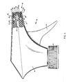
- FIGURE 1 is a partially broken away side elevational view of a nozzle of this invention attached to a hand actuated pump;
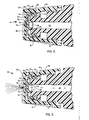
- FIGURE 2 is a sectional side elevational view of the nozzle shown in Figure 1 with the nozzle in the closed position;
- FIGURE 3 is a sectional side elevational view of the nozzle shown in Figure 1 with the nozzle in the spray position;
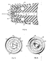
- FIGURE 4 is a sectional side elevational view of the nozzle shown in Figure 1 showing the nozzle in the stream position;
- FIGURE 5 is a front view of the sealing structure used in the nozzle shown in Figure 1; and
- FIGURE 6 is a rear elevational view of the sealing structure utilized in the nozzle shown in Figure 1.
- In Figures 1-6 there can be seen a nozzle of this invention, generally designated by the numeral 18. The nozzle is affixed to a hand-actuated pump, generally designated by the numeral 10.
Pump 10 is affixed to a container by means ofpump closure cap 12.Closure cap 12 forms a liquid-tight seal with the container so that the contents of the container cannot leak out should the container be tipped over.Pump housing 16 encloses the pumping mechanism for pumping the liquid from the container upon acutation ofpump trigger 14. The particular design of the pump mechanism is not critical to the operation of the nozzle of this invention as long as sufficient liquid pressure is provided upon actuation of the pump to operate the nozzle parts as hereinafter described. -
Nozzle 18 is affixed to the barrel of the pump, indicated by the numeral 20. Barrel 20 has ahelical thread 21 which cooperates withnozzle cap thread 36 for affixingnozzle 18 to the pump.Nozzle 18 has two component parts, anozzle cap 30 and aseal structure 38.Nozzle cap 30 has a nozzlecap end wall 33 with a dispensingaperture 32 therethrough. There is provided a planarinside surface 34 on the inside of nozzlecap end wall 33, Inside surface 34 surrounds dispensingaperture 32. Integrally formed with nozzlecap end wall 33 isnozzle cap skirt 31. This skirt carries the afore-describednozzle cap thread 36. -
Nozzle cap 30 enclosesseal structure 38.Seal structure 38 is mounted to the end of barrel 20 by means of a friction fit overcollar 26 which is located at the end of barrel 20'. Achieving the precise location ofseal structure 38 with respect to the end of barrel 20 is accomplished by means ofannular collar 24 which is an integral part of barrel 20. This collar acts as a stop structure for positioningseal structure 38.Seal structure 38 is integrally formed and has a peripheral seal portion 40 and acheck valve portion 46. To achieve the peripheral liquid-tight seal fucntion required of seal portion 40 there is provided sealinglip 42. Sealinglip 42 is dimensioned to achieve a peripheral liquid-tight engagement withnozzle cap 30 as is seen in Figures 1-4. Sealinglip 42 therefore prevents leakage between barrel 20 andnozzle cap 30. Other sealing arrangements, of course, may be utilized, the one utilized by the embodiment shown in the drawings being a preferred configuration. - Check
valve portion 46 has aseal member 48 and aspring member 50.Seal member 48 preferably provides aconical surface 54 which co-acts withannular groove 28 to provide an openable and closeable liquid-tight seal. Connected to the distal end ofconical surface 54, as can be seen in Figures 2-4, isspring member 50. For the embodiment shownspring member 50 comprises three arcuate segments which are dimensioned to be sufficiently resilient to provide the necessary spring function as hereinafter described. - Check
valve portion 46 preferably has a planar face with aswirl chamber 62 molded therein. Whenswirl chamber 62 is in abutment with the planarinside surface 34 ofnozzle cap 30 the swirl chamber will force the liquid to travel a path which will give a spray pattern. While the specific swirl chamber configuration shown in the drawings is a highly preferred configuration, it is understood that other configurations known in the art can be utilized to achieve this same function. - The particular nozzle shown in the drawings is one which is capable of effecting three modes of operation, a shut-off mode, a spray mode and a stream mode. In the shut-off mode, shown in Figure 2, passage of liquid through
bore 22 is prevented even if the pump is actuated ascheck valve portion 46 is blocked from the movement which would open the liquid-tight bore seal as the inside face ofnozzle cap 30 is pressing tightly thereagainst. In the other two modes checkvalve 46 would be free to move under the urging of liquid pressure inbore 22 upon pump actuation. - To achieve the second mode of operation, i.e., the spray mode,
nozzle cap 30 is loosened until it is displaced a distance away fromcheck valve portion 46 so thatseal member 48 is able to move and thus open the liquid-tight bore seal betweenconical surface 54 andannular groove 28. This mode is shown in Figure 3. However,nozzle cap 30 will still be close enough to checkvalve portion 46 whereby the planar face ofcheck valve portion 46 can abut insideplanar face 34. The abutment is necessary to force the liquid to pass throughswirl chamber 62 to effect the spray dispensing pattern. Withnozzle cap 30 in the spray position the pump is actuated by pullingtrigger 14. Liquid pressure builds inbore 22 until it is sufficient to overcome the spring bias-provided byspring member 50. Once the spring bias has been overcomeseal member 48 moves to open the liquid-tight bore seal and thus allows the pumped liquid to be forced throughswirl chamber 62 and outaperture 32. After a charge of liquid has been dispensedpump trigger 14 is released. Upon trigger release,seal member 48 returns to the seal position to provide a liquid-tight bore seal at the urging ofspring member 50. In some prior art pumps, e.g., U.S. 3,685,739, closing off of the bore after liquid has been dispensed relies upon the creation of a partial vacuum carried by the pump during its loading cycle. With these types of pumps there is a period of time before the bore can be closed off that air is sucked into the bore and into the pump chamber. This is disadvantageous as the sucked in air displaces liquid in the pump chamber and thus the subsequent charge of liquid will be of a reduced quantity. However, for the nozzle of this invention, the return ofseal member 48 to the seal position is effected by spring action means which is acting against liquid inbore 22. Thus there is a very little, if any at all; amount of air being sucked into the bore. By keeping air out of the bore a full charge of liquid is assured in the pump chamber. - To achieve the third mode of operation,
nozzle cap 30 is screwed further away fromcheck valve portion 46 so that the travel ofseal member 48 is unable to achieve abutment between the planar face ofseal member 48 and the planarinside surface 34 ofnozzle cap 30. Since there is no abutment the liquid is allowed to pass to dispensingaperture 32 without passing through the swirl chamber and thus a stream of liquid is dispensed instead of a spray. In thismode spring member 50 will return to achieve a liquid-tight bore seal as described for the first modes. - Not only can the nozzle of this invention have a three mode configuration, it is also possible to have a single mode configuration with or without nozzle shut-off, For example,
nozzle cap 30 can be mounted to barrel 20 by utilization of a bead and groove snap-on arrangement. With this configuration no shut-off will be available and the distance at which insideplanar surface 34 is displaced fromcheck valve portion 46 is fixed. This distance can be fixed so thatseal member 48 cannot obtain abutment with the end wall ofnozzle cap 30 or so that this abutment can be achieved. If abutment is not achieved there will be a stream dispensing mode or, on the other hand, if abutment is achieved there will be a spray dispensing mode. If it is desired to have a nozzle with a shut-off and spray mode, a configuration similar to the one shown in the drawings can be used with a modification to the cap and barrel threads so that the nozzle cap will be restricted to the extent it can move from the check valve. On the other hand, if a shut-off and stream mode only is desired, then the configuration shown inthe drawings may be used with the modification of designing the face of the check valve portion so that the liquid can go directly to the aperture.
Claims (9)
Applications Claiming Priority (2)
| Application Number | Priority Date | Filing Date | Title |
|---|---|---|---|
| US153771 | 1980-05-27 | ||
| US06/153,771 US4358057A (en) | 1980-05-27 | 1980-05-27 | Fluid dispenser method and apparatus |
Publications (2)
| Publication Number | Publication Date |
|---|---|
| EP0040851A1 true EP0040851A1 (en) | 1981-12-02 |
| EP0040851B1 EP0040851B1 (en) | 1986-04-23 |
Family
ID=22548679
Family Applications (1)
| Application Number | Title | Priority Date | Filing Date |
|---|---|---|---|
| EP81104028A Expired EP0040851B1 (en) | 1980-05-27 | 1981-05-26 | Fluid dispenser apparatus |
Country Status (4)
| Country | Link |
|---|---|
| US (1) | US4358057A (en) |
| EP (1) | EP0040851B1 (en) |
| CA (1) | CA1154413A (en) |
| DE (1) | DE3174451D1 (en) |
Cited By (1)
| Publication number | Priority date | Publication date | Assignee | Title |
|---|---|---|---|---|
| WO2018224206A1 (en) * | 2017-06-08 | 2018-12-13 | Aptar Radolfzell Gmbh | Discharge head for the nasal application of liquid from a pressure reservoir |
Families Citing this family (33)
| Publication number | Priority date | Publication date | Assignee | Title |
|---|---|---|---|---|
| US4515315A (en) * | 1983-06-08 | 1985-05-07 | Corsette Douglas Frank | Nozzle insert for a fluid dispenser |
| JPS61502239A (en) * | 1984-06-01 | 1986-10-09 | バンドシユ− ロバ−ト エル | Pump dispenser with slidable trigger |
| DE3443640A1 (en) * | 1984-11-29 | 1986-06-05 | Karlheinz 8902 Neusäß Kläger | SPRAYER NOZZLE OF A LIQUID SPRAYER |
| AU581041B2 (en) * | 1985-12-03 | 1989-02-09 | Atsushi Tada | A manually operated trigger type dispenser |
| US4898307A (en) * | 1988-08-25 | 1990-02-06 | Goody Products, Inc. | Spray caps |
| US4940186A (en) * | 1988-10-18 | 1990-07-10 | Atsushi Tada | Manually operated trigger type dispenser, a spinner for use in the dispenser, and a flow-pattern switching mechanism for use in the dispenser |
| FR2665848B1 (en) * | 1990-08-17 | 1992-10-30 | Aerosols & Bouchage | INCORPORATED VALVE NOZZLES. |
| US5234166A (en) * | 1990-10-25 | 1993-08-10 | Contico International, Inc. | Spinner assembly for a sprayer |
| US5385302A (en) * | 1990-10-25 | 1995-01-31 | Contico | Low cost trigger sprayer |
| US5368234A (en) * | 1991-12-13 | 1994-11-29 | Contico International, Inc. | Nozzle assembly for trigger sprayer |
| US5439178A (en) * | 1993-06-24 | 1995-08-08 | The Procter & Gamble Company | Pump device including multiple function collapsible pump chamber |
| FR2711930B1 (en) * | 1993-11-03 | 1996-01-26 | Sofab | Spraying device. |
| US5664703A (en) * | 1994-02-28 | 1997-09-09 | The Procter & Gamble Company | Pump device with collapsible pump chamber having supply container venting system and integral shipping seal |
| US5518147A (en) * | 1994-03-01 | 1996-05-21 | The Procter & Gamble Company | Collapsible pump chamber having predetermined collapsing pattern |
| US5509221A (en) * | 1994-05-10 | 1996-04-23 | Black & Decker Inc. | Spray nozzle assembly for an electric iron |
| US5476195A (en) * | 1994-10-06 | 1995-12-19 | Procter & Gamble Company | Pump device with collapsible pump chamber and including dunnage means |
| US5561901A (en) * | 1994-10-06 | 1996-10-08 | The Procter & Gamble Company | Assembly process including severing part of integral collapsible pump chamber |
| US5711460A (en) * | 1994-10-26 | 1998-01-27 | Yoshino Kogyosho Co., Ltd. | Trigger type liquid discharge device |
| US5593094A (en) * | 1995-02-07 | 1997-01-14 | Calmar Inc. | Pump sprayer having variable discharge |
| US5590837A (en) * | 1995-02-28 | 1997-01-07 | Calmar Inc. | Sprayer having variable spray pattern |
| US6234361B1 (en) | 1999-10-22 | 2001-05-22 | Owens-Illinois Closure Inc. | Pump dispenser piston provided with a plastic inlet check valve insert |
| US6443176B1 (en) | 1999-11-30 | 2002-09-03 | Hilmar Lumber, Inc. | Flush valve with rotatable grate |
| US6345738B1 (en) | 2000-03-16 | 2002-02-12 | Owen-Illinois Closure Inc. | Pump dispenser having body with fill-through conduit |
| US7036689B1 (en) * | 2002-04-22 | 2006-05-02 | Continental Afa Dispensing Company | Child-resistant trigger sprayer |
| WO2004108539A2 (en) * | 2003-06-05 | 2004-12-16 | Eliav Korakh | Liquid dispenser |
| DE10345342A1 (en) * | 2003-09-19 | 2005-04-28 | Engelhard Arzneimittel Gmbh | Producing an ivy leaf extract containing hederacoside C and alpha-hederin, useful for treating respiratory diseases comprises steaming comminuted ivy leaves before extraction |
| FR2909908B1 (en) * | 2006-12-15 | 2009-02-27 | Rexam Dispensing Systems Sas | SPRAY NOZZLE, DISPENSING MEMBER COMPRISING SUCH A NOZZLE, DISPENSER COMPRISING SUCH AN ORGAN AND USE OF SUCH A NOZZLE. |
| FR2961189B1 (en) * | 2010-06-14 | 2013-02-22 | Valois Sas | HEAD OF DISTRIBUTION OF FLUID PRODUCT. |
| FR2971768B1 (en) * | 2011-02-18 | 2013-03-22 | Valois Sas | HEAD OF DISTRIBUTION OF FLUID PRODUCT. |
| EP3272423B1 (en) * | 2016-07-20 | 2018-12-19 | Aptar Radolfzell GmbH | Discharge head and dispenser with a discharge head |
| EP3275552B1 (en) * | 2016-07-29 | 2019-10-16 | Aptar Radolfzell GmbH | Liquid dispenser with an applicator head |
| EP3978138A1 (en) * | 2017-12-21 | 2022-04-06 | SHL Medical AG | Method of production for a spray nozzle chip |
| US20220314252A1 (en) * | 2021-04-05 | 2022-10-06 | Market Ready, Inc. | Trigger sprayer assembly with dual valve system |
Citations (9)
| Publication number | Priority date | Publication date | Assignee | Title |
|---|---|---|---|---|
| US3685739A (en) * | 1970-08-07 | 1972-08-22 | Afa Corp | Liquid dispensing apparatus |
| US3840157A (en) * | 1972-10-16 | 1974-10-08 | J Hellenkamp | Hand operated sprayer |
| US3843030A (en) * | 1972-08-09 | 1974-10-22 | Leeds & Micallef | Multiple purpose nozzle |
| US3967765A (en) * | 1972-08-09 | 1976-07-06 | Leeds And Micallef | Multiple purpose nozzle |
| GB1497392A (en) * | 1976-11-05 | 1978-01-12 | Asl Airflow Ltd | Manually operable sprayer |
| US4161288A (en) * | 1976-10-05 | 1979-07-17 | Creative Dispensing Systems, Inc. | Fluid dispenser method and apparatus |
| GB1562817A (en) * | 1975-12-06 | 1980-03-19 | Yoshino Kogyosho Co Ltd | Trigger type spraying device |
| DE3021161A1 (en) * | 1979-06-05 | 1980-12-11 | Ethyl Prod | CHILD-SAFE SPRAYER NOZZLE |
| EP0032541A2 (en) * | 1980-01-18 | 1981-07-29 | Karlheinz Kläger | Adjustable nozzle for manually operated sprayer |
Family Cites Families (2)
| Publication number | Priority date | Publication date | Assignee | Title |
|---|---|---|---|---|
| US3437270A (en) * | 1968-03-12 | 1969-04-08 | Risdon Mfg Co | Self-sealing spray-actuator button |
| US4249681A (en) * | 1979-06-11 | 1981-02-10 | The Dow Chemical Company | Leak-proof sprayer |
-
1980
- 1980-05-27 US US06/153,771 patent/US4358057A/en not_active Expired - Lifetime
-
1981
- 1981-05-19 CA CA000377791A patent/CA1154413A/en not_active Expired
- 1981-05-26 EP EP81104028A patent/EP0040851B1/en not_active Expired
- 1981-05-26 DE DE8181104028T patent/DE3174451D1/en not_active Expired
Patent Citations (11)
| Publication number | Priority date | Publication date | Assignee | Title |
|---|---|---|---|---|
| US3685739A (en) * | 1970-08-07 | 1972-08-22 | Afa Corp | Liquid dispensing apparatus |
| US3843030A (en) * | 1972-08-09 | 1974-10-22 | Leeds & Micallef | Multiple purpose nozzle |
| US3967765A (en) * | 1972-08-09 | 1976-07-06 | Leeds And Micallef | Multiple purpose nozzle |
| US3840157A (en) * | 1972-10-16 | 1974-10-08 | J Hellenkamp | Hand operated sprayer |
| GB1562817A (en) * | 1975-12-06 | 1980-03-19 | Yoshino Kogyosho Co Ltd | Trigger type spraying device |
| US4161288A (en) * | 1976-10-05 | 1979-07-17 | Creative Dispensing Systems, Inc. | Fluid dispenser method and apparatus |
| GB1497392A (en) * | 1976-11-05 | 1978-01-12 | Asl Airflow Ltd | Manually operable sprayer |
| DE3021161A1 (en) * | 1979-06-05 | 1980-12-11 | Ethyl Prod | CHILD-SAFE SPRAYER NOZZLE |
| FR2458481A1 (en) * | 1979-06-05 | 1981-01-02 | Ethyl Prod | MECHANISM WITH A LIQUID DISPENSER NOZZLE |
| GB2051612A (en) * | 1979-06-05 | 1981-01-21 | Ethyl Prod | Nozzle assembly for a fluid dispenser |
| EP0032541A2 (en) * | 1980-01-18 | 1981-07-29 | Karlheinz Kläger | Adjustable nozzle for manually operated sprayer |
Cited By (5)
| Publication number | Priority date | Publication date | Assignee | Title |
|---|---|---|---|---|
| WO2018224206A1 (en) * | 2017-06-08 | 2018-12-13 | Aptar Radolfzell Gmbh | Discharge head for the nasal application of liquid from a pressure reservoir |
| EP3552644A1 (en) * | 2017-06-08 | 2019-10-16 | Aptar Radolfzell GmbH | Applicator head for nasal application of fluid from a pressure accumulator |
| CN110740772A (en) * | 2017-06-08 | 2020-01-31 | 阿普塔尔拉多尔夫策尔有限责任公司 | Discharge head for applying liquid from a pressure reservoir to a nose |
| CN110740772B (en) * | 2017-06-08 | 2022-03-29 | 阿普塔尔拉多尔夫策尔有限责任公司 | Discharge head for applying liquid from a pressure reservoir to a nose |
| US11833295B2 (en) | 2017-06-08 | 2023-12-05 | Aptar Radolfzell Gmbh | Discharge head for the nasal application of liquid from a pressure reservoir |
Also Published As
| Publication number | Publication date |
|---|---|
| DE3174451D1 (en) | 1986-05-28 |
| US4358057A (en) | 1982-11-09 |
| CA1154413A (en) | 1983-09-27 |
| EP0040851B1 (en) | 1986-04-23 |
Similar Documents
| Publication | Publication Date | Title |
|---|---|---|
| US4358057A (en) | Fluid dispenser method and apparatus | |
| US4313568A (en) | Fluid dispenser method and apparatus | |
| US4313569A (en) | Fluid dispenser method and apparatus | |
| CA1056351A (en) | Atomizing pump dispenser | |
| US4020978A (en) | Manually-operated dispenser | |
| US4346821A (en) | Child-resistant closures for container mounted spray dispensers | |
| US4735347A (en) | Single puff atomizing pump dispenser | |
| US4241853A (en) | Dispenser for either continuous or intermittent discharge | |
| US4958754A (en) | Dispenser or sprayer with vent system | |
| US5273191A (en) | Dispensing head for a squeeze dispenser | |
| CA1296302C (en) | Push up dispenser with capsule valve | |
| US3650473A (en) | Liquid dispensing apparatus | |
| US5810209A (en) | Dispenser with improved bottle connection | |
| US5725132A (en) | Dispenser with snap-fit container connection | |
| US6032814A (en) | Container assembly with improved container connection | |
| CA2429810A1 (en) | Dosing pump for liquid dispensers | |
| EP0625075A1 (en) | Spray pump package employing multiple orifices for dispensing liquid in different spray patterns with automatically adjusted optimized pump stroke for each pattern | |
| WO1986004984A1 (en) | Apparatus for dispensing products from a self-sealing dispenser | |
| US4503998A (en) | Trigger sprayer | |
| US5794822A (en) | Reciprocating fluid pump with improved bottle seal | |
| US3764046A (en) | Compressed air fluid product dispenser | |
| US4480768A (en) | Hand-operated pump | |
| EP0691161B1 (en) | A device for dispensing pastes or liquids from bottles or the like | |
| HU209099B (en) | Operating adapter may be placed onto spraying container | |
| US5887763A (en) | Reciprocating fluid pump with bottle closure having inner and outer rim seals |
Legal Events
| Date | Code | Title | Description |
|---|---|---|---|
| PUAI | Public reference made under article 153(3) epc to a published international application that has entered the european phase |
Free format text: ORIGINAL CODE: 0009012 |
|
| AK | Designated contracting states |
Designated state(s): BE DE FR GB NL |
|
| 17P | Request for examination filed |
Effective date: 19820525 |
|
| GRAA | (expected) grant |
Free format text: ORIGINAL CODE: 0009210 |
|
| RAP1 | Party data changed (applicant data changed or rights of an application transferred) |
Owner name: SPECIALTY PACKAGING PRODUCTS, INC. |
|
| AK | Designated contracting states |
Kind code of ref document: B1 Designated state(s): BE DE FR GB NL |
|
| PG25 | Lapsed in a contracting state [announced via postgrant information from national office to epo] |
Ref country code: NL Effective date: 19860423 Ref country code: FR Free format text: THE PATENT HAS BEEN ANNULLED BY A DECISION OF A NATIONAL AUTHORITY Effective date: 19860423 Ref country code: BE Effective date: 19860423 |
|
| REF | Corresponds to: |
Ref document number: 3174451 Country of ref document: DE Date of ref document: 19860528 |
|
| EN | Fr: translation not filed | ||
| NLV1 | Nl: lapsed or annulled due to failure to fulfill the requirements of art. 29p and 29m of the patents act | ||
| PLBE | No opposition filed within time limit |
Free format text: ORIGINAL CODE: 0009261 |
|
| STAA | Information on the status of an ep patent application or granted ep patent |
Free format text: STATUS: NO OPPOSITION FILED WITHIN TIME LIMIT |
|
| 26N | No opposition filed | ||
| PGFP | Annual fee paid to national office [announced via postgrant information from national office to epo] |
Ref country code: DE Payment date: 19900426 Year of fee payment: 10 |
|
| PG25 | Lapsed in a contracting state [announced via postgrant information from national office to epo] |
Ref country code: DE Effective date: 19920303 |
|
| PGFP | Annual fee paid to national office [announced via postgrant information from national office to epo] |
Ref country code: GB Payment date: 20000330 Year of fee payment: 20 |
|
| PG25 | Lapsed in a contracting state [announced via postgrant information from national office to epo] |
Ref country code: GB Free format text: LAPSE BECAUSE OF EXPIRATION OF PROTECTION Effective date: 20010525 |
|
| REG | Reference to a national code |
Ref country code: GB Ref legal event code: PE20 Effective date: 20010525 |