EP0039191A2 - Digital data transmission system with adaptive data transmission rate - Google Patents
Digital data transmission system with adaptive data transmission rate Download PDFInfo
- Publication number
- EP0039191A2 EP0039191A2 EP81301724A EP81301724A EP0039191A2 EP 0039191 A2 EP0039191 A2 EP 0039191A2 EP 81301724 A EP81301724 A EP 81301724A EP 81301724 A EP81301724 A EP 81301724A EP 0039191 A2 EP0039191 A2 EP 0039191A2
- Authority
- EP
- European Patent Office
- Prior art keywords
- data transmission
- transmitting
- digital data
- rate
- error rate
- Prior art date
- Legal status (The legal status is an assumption and is not a legal conclusion. Google has not performed a legal analysis and makes no representation as to the accuracy of the status listed.)
- Withdrawn
Links
Images

Classifications
-
- H—ELECTRICITY
- H04—ELECTRIC COMMUNICATION TECHNIQUE
- H04L—TRANSMISSION OF DIGITAL INFORMATION, e.g. TELEGRAPHIC COMMUNICATION
- H04L1/00—Arrangements for detecting or preventing errors in the information received
-
- H—ELECTRICITY
- H04—ELECTRIC COMMUNICATION TECHNIQUE
- H04L—TRANSMISSION OF DIGITAL INFORMATION, e.g. TELEGRAPHIC COMMUNICATION
- H04L1/00—Arrangements for detecting or preventing errors in the information received
- H04L1/24—Testing correct operation
-
- H—ELECTRICITY
- H04—ELECTRIC COMMUNICATION TECHNIQUE
- H04L—TRANSMISSION OF DIGITAL INFORMATION, e.g. TELEGRAPHIC COMMUNICATION
- H04L1/00—Arrangements for detecting or preventing errors in the information received
- H04L1/0001—Systems modifying transmission characteristics according to link quality, e.g. power backoff
- H04L1/0002—Systems modifying transmission characteristics according to link quality, e.g. power backoff by adapting the transmission rate
-
- H—ELECTRICITY
- H04—ELECTRIC COMMUNICATION TECHNIQUE
- H04Q—SELECTING
- H04Q2213/00—Indexing scheme relating to selecting arrangements in general and for multiplex systems
- H04Q2213/13166—Fault prevention
-
- H—ELECTRICITY
- H04—ELECTRIC COMMUNICATION TECHNIQUE
- H04Q—SELECTING
- H04Q2213/00—Indexing scheme relating to selecting arrangements in general and for multiplex systems
- H04Q2213/13199—Modem, modulation
-
- H—ELECTRICITY
- H04—ELECTRIC COMMUNICATION TECHNIQUE
- H04Q—SELECTING
- H04Q2213/00—Indexing scheme relating to selecting arrangements in general and for multiplex systems
- H04Q2213/13332—Broadband, CATV, dynamic bandwidth allocation
-
- Y—GENERAL TAGGING OF NEW TECHNOLOGICAL DEVELOPMENTS; GENERAL TAGGING OF CROSS-SECTIONAL TECHNOLOGIES SPANNING OVER SEVERAL SECTIONS OF THE IPC; TECHNICAL SUBJECTS COVERED BY FORMER USPC CROSS-REFERENCE ART COLLECTIONS [XRACs] AND DIGESTS
- Y02—TECHNOLOGIES OR APPLICATIONS FOR MITIGATION OR ADAPTATION AGAINST CLIMATE CHANGE
- Y02D—CLIMATE CHANGE MITIGATION TECHNOLOGIES IN INFORMATION AND COMMUNICATION TECHNOLOGIES [ICT], I.E. INFORMATION AND COMMUNICATION TECHNOLOGIES AIMING AT THE REDUCTION OF THEIR OWN ENERGY USE
- Y02D30/00—Reducing energy consumption in communication networks
- Y02D30/50—Reducing energy consumption in communication networks in wire-line communication networks, e.g. low power modes or reduced link rate
Definitions
- This invention relates generally to digital data transmission systems and more particularly to digital data transmission systems that utilize ordinary,telephone lines as the data transmission link.
- asynchronous digital data transmission is normally limited to 300 bits per second because this is the maximum data transmission rate that the telephone company can guarantee on the very worst of its telephone circuits.
- Many telephone connections will allow a transmission rate four to eight times as high, but the telephone company charges very high rates for telephone lines that they select in advance to be that good.
- the principal object of this invention is to provide a digital data transmission system which automatically adjusts the data transmission rate to achieve the highest data transmission rate that is compatible with a predetermined maximum error rate so that the maximum speed capabilities of any digital data transmission link can be fully utilized without expensive pre-selection of the transmission circuit.
- the present invention provides a data transmission system comprising means for transmitting digital data; means for receiving digital data; a digital transmission link coupled between said transmitting means and receiving means; means for measuring the error rate in the transmission of digital data from said transmitting means to said receiving means; means for comparing the measured error rate to predetermined limits; and means for varying the data transmission rate to achieve the highest transmission rate within predetermined error rate limits.
- the present invention also provides a method of transmitting digital data between digital data transmitting means and digital data receiving means comprising the steps of: transmitting test messages between said transmitting and receiving means at varying data transmission rates; measuring the error rates of said test messages; and transmitting data messages between said transmitting and receiving means at a data transmission rate at which the measured error rate falls within predetermined limits.
- test messages are sent at various speeds and the error rate thereof is measured to determine the highest transmission rate consistent with predetermined error rate limits. Thereafter, the data transmission rate is automatically decreased when the measured error rate reaches or exceeds a predetermined upper limit and is automatically increased when the measured error rate drops to or below a predetermined lower limit.
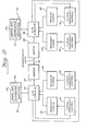
- Figure 1 is a block diagram showing one preferred embodiment of the invention which includes two computers 10 and 12 which are located at separate sites and are linked together by a digital data transmission system which includes I/O (input/output) circuits 14 and 16, respectively, modem (modulation-demodulation) circuits 18 and 20, respectively, and a transmission link 22 which may be an ordinary telephone circuit, a radio telephone circuit, or any other suitable data transmission link.
- Digital data can be transmitted between computers 10 and 12 in the conventional manner over the above-described digital data transmission system which as thus far described is entirely conventional.
- Computers 10 and 12 contain conventional error detection circuitry, which will not be described in detail, and conventional circuits for repeating any segment of the data transmission which is found to contain an error. This is also conventional. However, for the purposes of this invention, it is necessary to determine the error rate and this is done by error rate counters 24 and 26 which are responsive to the error detection circuitry of computers 10 and 12, respectively. Error rate counters 24 and 26 both produce an output signal which indicates the error rate per unit of time for their particular data receiver circuit, which is included in modems 18 and 20 and I/O circuits 14 and 16, respectively, which also include data transmitter circuits. The data receiver circuits and data transmitter circuits are not disclosed in detail since they are conventional. Only the clock portions are disclosed.
- both the data transmitter and receiver circuits are timed by variable frequency clocks 28 and 30, the frequency of which are controlled by clock frequency control circuits 32 and 34, respectively.
- Variable frequency clocks 28 and 30 enable the data transmission rate to be varied during the data transmission.
- Clock frequency control circuits 32 and 34 receive inputs from I/O circuits 14 and 16 and also from comparator circuits 36 and 38 which each receive an input from error rate counters 24 and 26. Each comparator circuit 36 and 38 produces an output indicating when the corresponding error rate is at or above apredetermined upper limit or is at or below a predetermined lower limit. In response to the output signal of comparator circuits 36 and 38, clock frequency control circuits 32 and 34 automatically raise the frequency of clocks 28 and 30 when the error rate is at or below the lower limit, which may be zero, and automatically lower the frequency of clocks 28 and 30 when the error rate is at or above the upper limit.
- a trans- , mission link is first established by conventional means, e.g. by dialing a telephone.
- Test messages are then exchanged between computers 10 and 12 at different data transmission rates until the highest transmission rate that is compatible with a predetermined maximum error rate is determined.
- Data transmission is then commenced at this transmission rate or a slightly lower rate. If the measured error rate rises to or above the predetermined maximum level, as determined by comparators 36 and 38, the transmission rate is automatically lowered by clock frequency controls 32 and 34. If the measured error rate falls to or below the predetermined minimum level, the transmission rate is automatically raised by clock frequency controls 32 and 34.
- the minimum error rate may be zero, and a time factor may be introduced whereby the error rate must remain at zero for a predetermined time before the data transmission rate is raised.
- Figure 2 shows a second preferred embodiment of the invention which includes two computers 40 and 42 which are located at separate rate sites and are linked together by a digital data transmission system which includes I/O (input/output) circuits 44 and 46, respectively, modem (modulation-demodulation) circuits 48 and 50, respectively, and a transmission link 52 which may be an ordinary telephone circuit, a radio telephone circuit, or any other suitable data transmission link.
- I/O input/output
- modem modulation-demodulation
- Computers 40 and 42 contain conventional error detection circuitry and have software routines 54 and 56, respectively, for computing the error rate. Computers 40 and 42 also have software routines 58 and 60, respectively, for comparing the error rate to predetermined upper and lower limits and indicating when to raise or lower the data transmission rate. Transmit clocks 62 and 64 are used to clock the data transmission of computers 40 and 42 while separate receive clocks 66 and 68 are used to clock the data reception thereof. The use of separate clocks for transmitting and receiving data enables each computer to transmit and receive at different transmission rates. Each of the clocks is controlled by a corresponding clock frequency control 70, 72, 74 and 76, all of which receive inputs from their respective I/O circuits 44 or 46 to set the clocks to the desired frequency.
Abstract
Description
- This invention relates generally to digital data transmission systems and more particularly to digital data transmission systems that utilize ordinary,telephone lines as the data transmission link.
- On ordinary telephone lines, asynchronous digital data transmission is normally limited to 300 bits per second because this is the maximum data transmission rate that the telephone company can guarantee on the very worst of its telephone circuits. Many telephone connections, however, will allow a transmission rate four to eight times as high, but the telephone company charges very high rates for telephone lines that they select in advance to be that good.
- The principal object of this invention is to provide a digital data transmission system which automatically adjusts the data transmission rate to achieve the highest data transmission rate that is compatible with a predetermined maximum error rate so that the maximum speed capabilities of any digital data transmission link can be fully utilized without expensive pre-selection of the transmission circuit.
- Accordingly, the present invention provides a data transmission system comprising means for transmitting digital data; means for receiving digital data; a digital transmission link coupled between said transmitting means and receiving means; means for measuring the error rate in the transmission of digital data from said transmitting means to said receiving means; means for comparing the measured error rate to predetermined limits; and means for varying the data transmission rate to achieve the highest transmission rate within predetermined error rate limits.
- The present invention also provides a method of transmitting digital data between digital data transmitting means and digital data receiving means comprising the steps of: transmitting test messages between said transmitting and receiving means at varying data transmission rates; measuring the error rates of said test messages; and transmitting data messages between said transmitting and receiving means at a data transmission rate at which the measured error rate falls within predetermined limits.
- At the start of a digital data transmission, test messages are sent at various speeds and the error rate thereof is measured to determine the highest transmission rate consistent with predetermined error rate limits. Thereafter, the data transmission rate is automatically decreased when the measured error rate reaches or exceeds a predetermined upper limit and is automatically increased when the measured error rate drops to or below a predetermined lower limit.
- In the drawings:
- Figure 1 is a block diagram of one preferred embodiment of the invention; and
- Fig. 2 is a block diagram of a second preferred embodiment.
- Figure 1 is a block diagram showing one preferred embodiment of the invention which includes two
computers 10 and 12 which are located at separate sites and are linked together by a digital data transmission system which includes I/O (input/output)circuits circuits 18 and 20, respectively, and atransmission link 22 which may be an ordinary telephone circuit, a radio telephone circuit, or any other suitable data transmission link. Digital data can be transmitted betweencomputers 10 and 12 in the conventional manner over the above-described digital data transmission system which as thus far described is entirely conventional. -
Computers 10 and 12 contain conventional error detection circuitry, which will not be described in detail, and conventional circuits for repeating any segment of the data transmission which is found to contain an error. This is also conventional. However, for the purposes of this invention, it is necessary to determine the error rate and this is done byerror rate counters computers 10 and 12, respectively.Error rate counters modems 18 and 20 and I/O circuits variable frequency clocks frequency control circuits Variable frequency clocks - Clock
frequency control circuits O circuits comparator circuits error rate counters comparator circuit comparator circuits frequency control circuits clocks clocks - In the operation of this embodiment, a trans- , mission link is first established by conventional means, e.g. by dialing a telephone. Test messages are then exchanged between
computers 10 and 12 at different data transmission rates until the highest transmission rate that is compatible with a predetermined maximum error rate is determined. Data transmission is then commenced at this transmission rate or a slightly lower rate. If the measured error rate rises to or above the predetermined maximum level, as determined bycomparators clock frequency controls clock frequency controls - Figure 2 shows a second preferred embodiment of the invention which includes two
computers circuits circuits transmission link 52 which may be an ordinary telephone circuit, a radio telephone circuit, or any other suitable data transmission link. -
Computers software routines 54 and 56, respectively, for computing the error rate.Computers software routines 58 and 60, respectively, for comparing the error rate to predetermined upper and lower limits and indicating when to raise or lower the data transmission rate.Transmit clocks 62 and 64 are used to clock the data transmission ofcomputers clocks clock frequency control O circuits - With the exception of having separate clocks for receiving and transmitting, the operation of the embodiment shown in Fig. 2 is substantially the same as the operation described above for the embodiment of Fig. 1.
Claims (4)
Applications Claiming Priority (2)
| Application Number | Priority Date | Filing Date | Title |
|---|---|---|---|
| US14137880A | 1980-04-18 | 1980-04-18 | |
| US141378 | 1980-04-18 |
Publications (2)
| Publication Number | Publication Date |
|---|---|
| EP0039191A2 true EP0039191A2 (en) | 1981-11-04 |
| EP0039191A3 EP0039191A3 (en) | 1982-04-07 |
Family
ID=22495436
Family Applications (1)
| Application Number | Title | Priority Date | Filing Date |
|---|---|---|---|
| EP81301724A Withdrawn EP0039191A3 (en) | 1980-04-18 | 1981-04-16 | Digital data transmission system with adaptive data transmission rate |
Country Status (6)
| Country | Link |
|---|---|
| EP (1) | EP0039191A3 (en) |
| JP (1) | JPS56164647A (en) |
| KR (1) | KR830005782A (en) |
| BR (1) | BR8102439A (en) |
| IL (1) | IL62566A0 (en) |
| NO (1) | NO811282L (en) |
Cited By (23)
| Publication number | Priority date | Publication date | Assignee | Title |
|---|---|---|---|---|
| GB2118807A (en) * | 1982-02-13 | 1983-11-02 | Canon Kk | Facsimile system |
| GB2124851A (en) * | 1982-04-07 | 1984-02-22 | Canon Kk | Facsimile system |
| EP0112697A2 (en) * | 1982-12-21 | 1984-07-04 | Plessey Overseas Limited | Priority coding system |
| EP0154565A2 (en) * | 1984-03-08 | 1985-09-11 | Codex Corporation | Modem |
| US4606044A (en) * | 1983-03-09 | 1986-08-12 | Ricoh Company, Ltd. | Adjusting data transmission rate based on received signal quality |
| EP0192120A2 (en) * | 1985-02-04 | 1986-08-27 | DEVAU Lemppenau GmbH | Data transmission process and device for remote control |
| US4710925A (en) * | 1983-12-12 | 1987-12-01 | Canon Kabushiki Kaisha | Data communication system |
| WO1988004496A1 (en) * | 1986-12-02 | 1988-06-16 | Plessey Overseas Limited | Data transmission system with automatic repeat request |
| US4829524A (en) * | 1985-02-28 | 1989-05-09 | Canon Kabushiki Kaisha | Data communication apparatus |
| GB2223914A (en) * | 1988-08-04 | 1990-04-18 | Norand Corp | Mobile radio data communication system and method |
| US5007047A (en) * | 1988-12-02 | 1991-04-09 | Codex Corporation | Adaptive rate control for echo cancelling modem |
| EP0423485A1 (en) * | 1989-10-05 | 1991-04-24 | Robert Bosch Gmbh | Method and device for bidirectional transmission of data |
| GB2253546A (en) * | 1991-03-04 | 1992-09-09 | Mitsubishi Electric Corp | Radio communication apparatus with stored coding/decoding procedures |
| EP0637150A1 (en) * | 1993-07-26 | 1995-02-01 | AT&T Corp. | A 1200 bit per second fallback method for use in mobile radio |
| EP0643508A1 (en) * | 1993-09-13 | 1995-03-15 | Thomson-Csf | Method and apparatus for data transmission rate adjustment in a radio data link |
| EP0647043A2 (en) * | 1993-10-04 | 1995-04-05 | AT&T Corp. | Data-driven autorating for use in data communications |
| DE4402512C1 (en) * | 1994-01-28 | 1995-06-01 | Ruediger Prof Dr Ing Reis | Data communication system for data pumps |
| DE4343982C1 (en) * | 1993-12-22 | 1995-08-17 | Siemens Ag | Line connection system for digital telephone communication network |
| WO1996017454A1 (en) * | 1994-11-30 | 1996-06-06 | Qualcomm Incorporated | Method and apparatus for testing a digital communication channel at variable or fixed data rates |
| EP0901300A1 (en) * | 1997-09-08 | 1999-03-10 | Siemens Aktiengesellschaft | Method and arrangement for automatic configuration of a subscriber equipment with interface units |
| DE10035368A1 (en) * | 2000-07-20 | 2002-02-14 | Isoft Gmbh | Devices, computer program product and method for managing data transmission uses a connection-oriented data link to convert real data waiting to be transmitted into consecutive data packets. |
| US7406548B2 (en) | 2004-03-26 | 2008-07-29 | Hewlett-Packard Development Company, L.P. | Systems and methods for responding to a data transfer |
| US9109928B2 (en) * | 2007-08-16 | 2015-08-18 | International Business Machines Corporation | Methods and apparatus for efficient and adaptive transmission of data in data collection networks |
Families Citing this family (2)
| Publication number | Priority date | Publication date | Assignee | Title |
|---|---|---|---|---|
| JPS5991752A (en) * | 1982-11-18 | 1984-05-26 | Japanese National Railways<Jnr> | Switching system of transmission speed |
| JPS6326134A (en) * | 1986-07-18 | 1988-02-03 | Sanyo Electric Co Ltd | Two-way data transmission method |
Citations (3)
| Publication number | Priority date | Publication date | Assignee | Title |
|---|---|---|---|---|
| GB1521091A (en) * | 1974-11-20 | 1978-08-09 | Siemens Ag | Circuit arrangements for use in data transmission systems |
| DE2735203B1 (en) * | 1977-08-04 | 1978-11-02 | Siemens Ag | Method and arrangement for bit error rate measurement in a time division multiplex system |
| GB1543698A (en) * | 1977-04-04 | 1979-04-04 | Xerox Corp | Modem speed selector |
-
1981
- 1981-04-02 IL IL62566A patent/IL62566A0/en unknown
- 1981-04-13 NO NO811282A patent/NO811282L/en unknown
- 1981-04-15 BR BR8102439A patent/BR8102439A/en unknown
- 1981-04-15 KR KR1019810001292A patent/KR830005782A/en unknown
- 1981-04-16 EP EP81301724A patent/EP0039191A3/en not_active Withdrawn
- 1981-04-17 JP JP5728381A patent/JPS56164647A/en active Pending
Patent Citations (3)
| Publication number | Priority date | Publication date | Assignee | Title |
|---|---|---|---|---|
| GB1521091A (en) * | 1974-11-20 | 1978-08-09 | Siemens Ag | Circuit arrangements for use in data transmission systems |
| GB1543698A (en) * | 1977-04-04 | 1979-04-04 | Xerox Corp | Modem speed selector |
| DE2735203B1 (en) * | 1977-08-04 | 1978-11-02 | Siemens Ag | Method and arrangement for bit error rate measurement in a time division multiplex system |
Cited By (37)
| Publication number | Priority date | Publication date | Assignee | Title |
|---|---|---|---|---|
| GB2118807A (en) * | 1982-02-13 | 1983-11-02 | Canon Kk | Facsimile system |
| GB2124851A (en) * | 1982-04-07 | 1984-02-22 | Canon Kk | Facsimile system |
| EP0112697A2 (en) * | 1982-12-21 | 1984-07-04 | Plessey Overseas Limited | Priority coding system |
| EP0112697A3 (en) * | 1982-12-21 | 1986-02-26 | Plessey Overseas Limited | Priority coding system |
| US4606044A (en) * | 1983-03-09 | 1986-08-12 | Ricoh Company, Ltd. | Adjusting data transmission rate based on received signal quality |
| US4710925A (en) * | 1983-12-12 | 1987-12-01 | Canon Kabushiki Kaisha | Data communication system |
| EP0154565A3 (en) * | 1984-03-08 | 1987-07-15 | Codex Corporation | Modem |
| EP0154565A2 (en) * | 1984-03-08 | 1985-09-11 | Codex Corporation | Modem |
| US4756007A (en) * | 1984-03-08 | 1988-07-05 | Codex Corporation | Adaptive communication rate modem |
| EP0192120A2 (en) * | 1985-02-04 | 1986-08-27 | DEVAU Lemppenau GmbH | Data transmission process and device for remote control |
| EP0192120A3 (en) * | 1985-02-04 | 1988-09-21 | Peter Dietrich | Data transmission process and device for remote control |
| US4829524A (en) * | 1985-02-28 | 1989-05-09 | Canon Kabushiki Kaisha | Data communication apparatus |
| WO1988004496A1 (en) * | 1986-12-02 | 1988-06-16 | Plessey Overseas Limited | Data transmission system with automatic repeat request |
| AU594216B2 (en) * | 1986-12-02 | 1990-03-01 | Siemens Aktiengesellschaft | Data transmission system with automatic repeat request |
| US4939731A (en) * | 1986-12-02 | 1990-07-03 | Plessey Overseas Limited | Data transmission system with automatic repeat request |
| GB2223914A (en) * | 1988-08-04 | 1990-04-18 | Norand Corp | Mobile radio data communication system and method |
| GB2223914B (en) * | 1988-08-04 | 1992-11-18 | Norand Corp | Mobile radio data communication system and method |
| US5007047A (en) * | 1988-12-02 | 1991-04-09 | Codex Corporation | Adaptive rate control for echo cancelling modem |
| EP0423485A1 (en) * | 1989-10-05 | 1991-04-24 | Robert Bosch Gmbh | Method and device for bidirectional transmission of data |
| GB2253546A (en) * | 1991-03-04 | 1992-09-09 | Mitsubishi Electric Corp | Radio communication apparatus with stored coding/decoding procedures |
| GB2253546B (en) * | 1991-03-04 | 1995-04-19 | Mitsubishi Electric Corp | Radio communication apparatus with stored coding/decoding procedures |
| EP0637150A1 (en) * | 1993-07-26 | 1995-02-01 | AT&T Corp. | A 1200 bit per second fallback method for use in mobile radio |
| EP0643508A1 (en) * | 1993-09-13 | 1995-03-15 | Thomson-Csf | Method and apparatus for data transmission rate adjustment in a radio data link |
| FR2710213A1 (en) * | 1993-09-13 | 1995-03-24 | Thomson Csf | Method and device for regulating the information rate of a radio link |
| EP0647043A3 (en) * | 1993-10-04 | 1997-02-26 | At & T Corp | Data-driven autorating for use in data communications. |
| EP0647043A2 (en) * | 1993-10-04 | 1995-04-05 | AT&T Corp. | Data-driven autorating for use in data communications |
| DE4343982C1 (en) * | 1993-12-22 | 1995-08-17 | Siemens Ag | Line connection system for digital telephone communication network |
| DE4402512C1 (en) * | 1994-01-28 | 1995-06-01 | Ruediger Prof Dr Ing Reis | Data communication system for data pumps |
| WO1996017454A1 (en) * | 1994-11-30 | 1996-06-06 | Qualcomm Incorporated | Method and apparatus for testing a digital communication channel at variable or fixed data rates |
| EP1780928A1 (en) * | 1994-11-30 | 2007-05-02 | Qualcomm, Incorporated | Method and apparatus for testing a digital communication channel at variable or fixed data rates |
| EP0901300A1 (en) * | 1997-09-08 | 1999-03-10 | Siemens Aktiengesellschaft | Method and arrangement for automatic configuration of a subscriber equipment with interface units |
| WO1999013678A1 (en) * | 1997-09-08 | 1999-03-18 | Siemens Aktiengesellschaft | Method and device for automatic configuration of a subscriber's installation with a network interface unit |
| US6704323B1 (en) | 1997-09-08 | 2004-03-09 | Siemens Aktiengesellschaft | Method and device for automatic configuration of a subscriber's installation with a network interface unit |
| DE10035368A1 (en) * | 2000-07-20 | 2002-02-14 | Isoft Gmbh | Devices, computer program product and method for managing data transmission uses a connection-oriented data link to convert real data waiting to be transmitted into consecutive data packets. |
| DE10035368C2 (en) * | 2000-07-20 | 2003-10-09 | Adisoft Ag | Device, method and computer program product for managing data transmission |
| US7406548B2 (en) | 2004-03-26 | 2008-07-29 | Hewlett-Packard Development Company, L.P. | Systems and methods for responding to a data transfer |
| US9109928B2 (en) * | 2007-08-16 | 2015-08-18 | International Business Machines Corporation | Methods and apparatus for efficient and adaptive transmission of data in data collection networks |
Also Published As
| Publication number | Publication date |
|---|---|
| IL62566A0 (en) | 1981-06-29 |
| KR830005782A (en) | 1983-09-09 |
| JPS56164647A (en) | 1981-12-17 |
| BR8102439A (en) | 1981-12-29 |
| NO811282L (en) | 1981-10-19 |
| EP0039191A3 (en) | 1982-04-07 |
Similar Documents
| Publication | Publication Date | Title |
|---|---|---|
| EP0039191A2 (en) | Digital data transmission system with adaptive data transmission rate | |
| CA1281095C (en) | Multipurpose digital integrated circuit for communication and control network | |
| EP0281307B1 (en) | Asynchronous interface and method for coupling data between a data module and a serial asynchronous peripheral | |
| US5241565A (en) | Method and apparatus for effecting efficient transmission of data | |
| US4369516A (en) | Self-clocking data transmission system | |
| US5862141A (en) | Variable bitrate radio modem system to enhance data transmission and reduce error rates | |
| EP0296253B1 (en) | Discrimination timing control circuit | |
| US8374321B2 (en) | Bit rate matching system and method | |
| CA1241378A (en) | Multi-speed, full duplex modem | |
| EP0180066A2 (en) | Multidrop modem communication system | |
| US5132987A (en) | Bidirectional communication line buffer apparatus | |
| CA1172330A (en) | Multiport modem and the use thereof in a method and a system for testing a multilevel communication network | |
| US4222118A (en) | Intelligent automatic gain control circuit | |
| EP0206443B1 (en) | Decoder for digital radio-received data and method | |
| US4768204A (en) | Method and apparatus for transmitting signals between a master station and a number of terminals | |
| EP0047833A1 (en) | Data communication signalling interface | |
| US5208831A (en) | Network interface system | |
| CA2424213C (en) | Bit rate matching system and method | |
| EP0360721A2 (en) | Method and apparatus for high speed asynchronous communication | |
| US5010480A (en) | Communication interface for interfacing a data bus of a computer to a high speed bipolar communication system | |
| JPH0522212A (en) | Transmission power control system | |
| JP3166669B2 (en) | Received input level detection value correction circuit, correction method, and wireless transmission / reception device | |
| US5152008A (en) | Signal control apparatus capable of readily changing an apparatus output signal | |
| CA1303178C (en) | Multipurpose digital integrated circuit for communication and control network | |
| JP2946899B2 (en) | Transmission power control method |
Legal Events
| Date | Code | Title | Description |
|---|---|---|---|
| PUAI | Public reference made under article 153(3) epc to a published international application that has entered the european phase |
Free format text: ORIGINAL CODE: 0009012 |
|
| AK | Designated contracting states |
Designated state(s): BE CH DE FR GB IT NL SE |
|
| PUAL | Search report despatched |
Free format text: ORIGINAL CODE: 0009013 |
|
| AK | Designated contracting states |
Designated state(s): BE CH DE FR GB IT NL SE |
|
| RHK1 | Main classification (correction) |
Ipc: H04L 1/00 |
|
| 17P | Request for examination filed |
Effective date: 19820503 |
|
| STAA | Information on the status of an ep patent application or granted ep patent |
Free format text: STATUS: THE APPLICATION IS DEEMED TO BE WITHDRAWN |
|
| 18D | Application deemed to be withdrawn |
Effective date: 19830523 |
|
| PGFP | Annual fee paid to national office [announced via postgrant information from national office to epo] |
Ref country code: GR Payment date: 19900627 Year of fee payment: 4 |
|
| RIN1 | Information on inventor provided before grant (corrected) |
Inventor name: JOHNSTONE, RICHARD Inventor name: KIRKHAM, EDWARD E. |