EP0035898A1 - Microwave generated plasma light source apparatus - Google Patents
Microwave generated plasma light source apparatus Download PDFInfo
- Publication number
- EP0035898A1 EP0035898A1 EP81300965A EP81300965A EP0035898A1 EP 0035898 A1 EP0035898 A1 EP 0035898A1 EP 81300965 A EP81300965 A EP 81300965A EP 81300965 A EP81300965 A EP 81300965A EP 0035898 A1 EP0035898 A1 EP 0035898A1
- Authority
- EP
- European Patent Office
- Prior art keywords
- bulb
- light
- cavity
- discharge
- microwave
- Prior art date
- Legal status (The legal status is an assumption and is not a legal conclusion. Google has not performed a legal analysis and makes no representation as to the accuracy of the status listed.)
- Granted
Links
- 239000000126 substance Substances 0.000 claims abstract description 14
- GYHNNYVSQQEPJS-UHFFFAOYSA-N Gallium Chemical compound [Ga] GYHNNYVSQQEPJS-UHFFFAOYSA-N 0.000 claims description 30
- 229910052733 gallium Inorganic materials 0.000 claims description 30
- QSHDDOUJBYECFT-UHFFFAOYSA-N mercury Chemical compound [Hg] QSHDDOUJBYECFT-UHFFFAOYSA-N 0.000 claims description 30
- 229910052753 mercury Inorganic materials 0.000 claims description 29
- VYPSYNLAJGMNEJ-UHFFFAOYSA-N Silicium dioxide Chemical compound O=[Si]=O VYPSYNLAJGMNEJ-UHFFFAOYSA-N 0.000 claims description 12
- 230000002093 peripheral effect Effects 0.000 claims description 4
- 229910052736 halogen Inorganic materials 0.000 claims description 3
- 150000002367 halogens Chemical class 0.000 claims description 3
- QKEOZZYXWAIQFO-UHFFFAOYSA-M mercury(1+);iodide Chemical compound [Hg]I QKEOZZYXWAIQFO-UHFFFAOYSA-M 0.000 description 17
- 229910052751 metal Inorganic materials 0.000 description 16
- 239000002184 metal Substances 0.000 description 16
- 230000005672 electromagnetic field Effects 0.000 description 15
- XKRFYHLGVUSROY-UHFFFAOYSA-N Argon Chemical compound [Ar] XKRFYHLGVUSROY-UHFFFAOYSA-N 0.000 description 14
- 230000000087 stabilizing effect Effects 0.000 description 14
- 239000007789 gas Substances 0.000 description 9
- 238000005286 illumination Methods 0.000 description 9
- 229910052786 argon Inorganic materials 0.000 description 7
- 230000000694 effects Effects 0.000 description 7
- 239000000463 material Substances 0.000 description 6
- 238000012986 modification Methods 0.000 description 6
- 230000004048 modification Effects 0.000 description 6
- 239000010453 quartz Substances 0.000 description 6
- 238000001816 cooling Methods 0.000 description 5
- 239000003989 dielectric material Substances 0.000 description 5
- 239000003990 capacitor Substances 0.000 description 4
- 238000010276 construction Methods 0.000 description 3
- 230000007423 decrease Effects 0.000 description 3
- 150000002739 metals Chemical class 0.000 description 3
- 230000010355 oscillation Effects 0.000 description 3
- 238000004804 winding Methods 0.000 description 3
- ZCYVEMRRCGMTRW-UHFFFAOYSA-N 7553-56-2 Chemical compound [I] ZCYVEMRRCGMTRW-UHFFFAOYSA-N 0.000 description 2
- OKTJSMMVPCPJKN-UHFFFAOYSA-N Carbon Chemical compound [C] OKTJSMMVPCPJKN-UHFFFAOYSA-N 0.000 description 2
- 230000002411 adverse Effects 0.000 description 2
- 238000010586 diagram Methods 0.000 description 2
- 230000005684 electric field Effects 0.000 description 2
- 238000007496 glass forming Methods 0.000 description 2
- 229910002804 graphite Inorganic materials 0.000 description 2
- 239000010439 graphite Substances 0.000 description 2
- XMBWDFGMSWQBCA-UHFFFAOYSA-N hydrogen iodide Chemical compound I XMBWDFGMSWQBCA-UHFFFAOYSA-N 0.000 description 2
- 230000000977 initiatory effect Effects 0.000 description 2
- 229910052740 iodine Inorganic materials 0.000 description 2
- 239000011630 iodine Substances 0.000 description 2
- 230000031700 light absorption Effects 0.000 description 2
- 238000004519 manufacturing process Methods 0.000 description 2
- 239000000203 mixture Substances 0.000 description 2
- 229910052756 noble gas Inorganic materials 0.000 description 2
- 230000003287 optical effect Effects 0.000 description 2
- 230000001105 regulatory effect Effects 0.000 description 2
- 238000004904 shortening Methods 0.000 description 2
- 238000001228 spectrum Methods 0.000 description 2
- 229910052691 Erbium Inorganic materials 0.000 description 1
- FQDZSSLDYLFYQF-UHFFFAOYSA-N [Hg].[I] Chemical compound [Hg].[I] FQDZSSLDYLFYQF-UHFFFAOYSA-N 0.000 description 1
- 230000002159 abnormal effect Effects 0.000 description 1
- 238000000149 argon plasma sintering Methods 0.000 description 1
- 238000005452 bending Methods 0.000 description 1
- 239000006229 carbon black Substances 0.000 description 1
- 230000015556 catabolic process Effects 0.000 description 1
- 238000010411 cooking Methods 0.000 description 1
- 230000003247 decreasing effect Effects 0.000 description 1
- 230000007547 defect Effects 0.000 description 1
- 125000000664 diazo group Chemical group [N-]=[N+]=[*] 0.000 description 1
- 238000005530 etching Methods 0.000 description 1
- 238000001704 evaporation Methods 0.000 description 1
- 230000008020 evaporation Effects 0.000 description 1
- 230000005284 excitation Effects 0.000 description 1
- DWRNSCDYNYYYHT-UHFFFAOYSA-K gallium(iii) iodide Chemical compound I[Ga](I)I DWRNSCDYNYYYHT-UHFFFAOYSA-K 0.000 description 1
- 238000005259 measurement Methods 0.000 description 1
- 230000008018 melting Effects 0.000 description 1
- 238000002844 melting Methods 0.000 description 1
- 229920006395 saturated elastomer Polymers 0.000 description 1
- 238000009738 saturating Methods 0.000 description 1
- 125000006850 spacer group Chemical group 0.000 description 1
- 229910001220 stainless steel Inorganic materials 0.000 description 1
- 239000010935 stainless steel Substances 0.000 description 1
- 239000007858 starting material Substances 0.000 description 1
- GUVRBAGPIYLISA-UHFFFAOYSA-N tantalum atom Chemical class [Ta] GUVRBAGPIYLISA-UHFFFAOYSA-N 0.000 description 1
- 238000009834 vaporization Methods 0.000 description 1
- 230000008016 vaporization Effects 0.000 description 1
Images


Classifications
-
- H—ELECTRICITY
- H01—ELECTRIC ELEMENTS
- H01J—ELECTRIC DISCHARGE TUBES OR DISCHARGE LAMPS
- H01J65/00—Lamps without any electrode inside the vessel; Lamps with at least one main electrode outside the vessel
- H01J65/04—Lamps in which a gas filling is excited to luminesce by an external electromagnetic field or by external corpuscular radiation, e.g. for indicating plasma display panels
- H01J65/042—Lamps in which a gas filling is excited to luminesce by an external electromagnetic field or by external corpuscular radiation, e.g. for indicating plasma display panels by an external electromagnetic field
- H01J65/044—Lamps in which a gas filling is excited to luminesce by an external electromagnetic field or by external corpuscular radiation, e.g. for indicating plasma display panels by an external electromagnetic field the field being produced by a separate microwave unit
-
- H—ELECTRICITY
- H01—ELECTRIC ELEMENTS
- H01J—ELECTRIC DISCHARGE TUBES OR DISCHARGE LAMPS
- H01J61/00—Gas-discharge or vapour-discharge lamps
- H01J61/02—Details
- H01J61/54—Igniting arrangements, e.g. promoting ionisation for starting
Abstract
Description
- The present invention relates to a light source utilizing a microwave generated plasma discharge..
- Recently, a light source utilizing high frequency discharge, particularly, a microwave generated plasma discharge, has been considered in view of the long life thereby provided, which is significantly longer than the life of a conventional light source having electrodes which are relatively easily consumed.
- A light source using high frequency discharge has es- sentiallyno electrode and thus there is no thermal loss such as is inherent to a light source having electrodes. Further, the discharge impedance thereof at the time when discharge starts is not significantly different from that during the stable discharge. In addition to these advantages, since discharge power is localized around an envelope of the lamp bulb, it is easy to couple power to the light source at the discharge starting time. Thus, the time required to achieve the maximum lamp output is short.
- Fig. 1 shows, in vertical cross section, a conventional microwave generated plasma light source constructed by incorporating the above features and Fig. 2 is a cross section of the light source taken along a line II-II in Fig. 1.
- In these Figures, a magnetron 1 enclosed by an
envelope 10 and cooled by acooling fan 7 generates microwave energy which is radiated through amagnetron antenna 2 into awaveguide tube 3. The microwave energy propagates along thewaveguide tube 3 and is radiated through afeeding opening 5 to acavity 49 having a semicircular cross section and defined by amesh 9 and asemicircular light reflector 4 having a plurality of gas passages formed therein to thus establish a microwave electromagnetic field therein. A discharge occurs in a Noble gas encapsulated in adischarge bulb 6 due to the microwave electromagnetic field to-thus heat the bulb wall or envelope and to thereby evaporate a metal such as mercury also encapsulated in the bulb. Then, discharge in the gaseous metal takes place. With this gaseous metal discharge, the microwave energy is caused to be absorbed by thedischarge bulb 6 substantially completely during its propagation along the length of thedischarge bulb 6 through several reflections within thecavity 49 so that the microwave energy is converted into discharge energy substantially completely. That is, the bulb is excited in a non-resonance state. - The
reflector 4 defining a portion of thecavity 49 reflects light directed rearwardly of the lamp bulb so that all the light from the bulb is directed to pass through an open end of the cavity which is covered by amesh member 9 which is transparent to light but only translucent to microwaves to thereby utilize the light produced by the gaseous metal discharge effectively. - Cooling air supplied by the
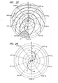
fan 7, after cooling of the magnetron 1, passes through theair passages 8 of thereflector 4 to cool thedischarge bulb 6 and is discharged from thecavity 49 through the mesh member 9: - In the conventional microwave generated plasma light source constructed as above, the microwave electromagnetic waves are distributed in the
cavity 49 having a semicircular cross section as shown in Fig. 3. However, the distribution is not uniform. Therefore, the discharge in thedischarge bulb 6 is not uniform and thus the light intensity distribution is not uniform in the axial direction of the bulb. - One approach of eliminating the non-uniformity of light intensity distribution is to alter the shape of, for example, the
reflector 4. This approach, however, is not practical because it is difficult as a practical matter to provide a reflector of a shape corresponding to the microwave electric field distribution in the cavity. Another approach is to use as small a discharge bulb as possible to thereby obtain a uniform discharge. Since, in this case, however, thecavity 49 is used in the non-resonance state, it is impossible to supply sufficient power to thedischarge bulb 6 to excite it,resulting in a low discharge efficiency. Therefore, the device thus constructed is not suitable for use as an ultraviolet ray source for the photographic plate making,where a high light intensity and a highly uniform illumination distribution over an area to be illuminated are required. - An object of the present invention is to provide a microwave generated plasma light source apparatus with which a uniform illumination distribution is provided and which is suitable for use as an ultraviolet ray source, for example for a photographic plate making device.
- The above object is achieved by the present invention by the use of a microwave cavity as a resonator when the discharge bulb is operated and by selecting the shape of the discharge bulb so that it functions as a point light source.
- More specifically, the above and other objects of the invention are met by a microwave generated plasma light source apparatus including a microwave generator, a microwave cavity having a light reflecting member forming at least a portion of the cavity, with the microwave generator being coupled through a feeding opening in the cavity to the cavity, a member transparent to light and opaque to microwaves disposed across an opening of the cavity opposite the feeding opening, a waveguide for guiding microwaves generated by the microwave generator to the feeding opening of the cavity, and a non-electrode discharge bulb disposed at a position in the cavity such that the cavity operates as a resonant cavity at least when the bulb is emitting light. The bulb encapsulates at least one discharge light emissive suostance and has a shape and is sufficiently small that the bulb functions substantially as a point light source, taking into consideration the size and shape of the light reflecting member.
- Preferably, the light reflecting member is a light reflecting shell having rotational symmetry. At least a portion of the light reflecting shell may conform to the shape of the bulb and a wing portion may be provided extending from a peripheral edge of the shell and an inner surface of the wing portion is made non-reflective to light. A lens may be provided for collecting or scattering light passing through the member which is transparent to light and opaque to microwaves. An electrically conductive discharge start assisting member may be disposed at least in the vicinity of the bulb for concentrating a magnetic field,with the start assisting member in one preferred embodiment being encapsulated in the bulb. The start assisting member is preferably disposed on a side of the bulb facing the feeding opening. The discharge start assisting member may have the shape of a wire or may be an electrically conductive member having a dielectric covering therearound. A space may be provided between the conductive member and the dielectric cover which is at a reduced pressure.
- The light reflecting member may be formed with a pair of opposed cut-off sleeves into which a pair of supporting members of the bulb are inserted to support the bulb. The bulb may have the supporting members formed integrally therewith.
- Preferably, the discharge light emissive substance encapsulated in the bulb is mercury of 7 x 10 gram atom/cc to 60 x 10-6 gram atom/cc, gallium af at least 1 x 10⁻⁷gram atom/cc and a halogen of 1.5 x 10⁻⁷ to 50 x 10-7 gram atom/cc. The bulb may be made of transparent quartz glass and should have an inner diameter such that a ratio of an outer surface area of the bulb to input microwave power is in a range of 1.5 to 15 mm2/W. The weight of the discharge bulb with respect to the microwave input power should be no more than 3.0 x 10 g/W. The microwave generator may generate the microwave intermittently in which case the rest interval should be no more than 5 msec. The microwave generator may be a magnetron with a full-wave voltage doubler power supply used to drive the magnetron. The length of the waveguide should be selected such that the operation of the magnetron is within a phase width of a quarter wavelength with respect to a sink region of the magnetron immediately after the bulb is ignited.
-
- Fig. 1 is a cross section of the conventional microwave discharge light source;
- Fig. 2 is a cross section of the microwave discharge light source taken along a line II-II in Fig. 1;
- Fig. 3 shows a microwave electric field distribution in a cavity of the conventional microwave discharge light source;
- Fig. 4 is a cross sectional view of a preferred embodiment of the present invention;
- Fig. 5 is a cross section of the present microwave discharge light source taken along a line V-V in Fig. 4;
- Fig. 6 is a perspective view of a modification of the cavity portion of the embodiment in Fig. 4;
- Fig. 7 is a cross section of a cavity of a second embodiment of the present invention;
- Fig. 8 is a cross section of a modification of the cavity of the second embodiment of the present invention;
- Figs. 9 through 11 show a third embodiment of the present invention in which Fig. 9 is a cross section thereof,
- Fig. 10 is a cross section of the cavity portion thereof and
- Fig. 11 is an enlarged view of an essential portion thereof;
- Figs. 12 through 14 show modifications of the discharge bulb of the third embodiment of the present invention, respectively;
- Fig. 15 is similar to Fig. 11, showing a modification of the third embodiment of the present invention;
- Figs. 16 through 18 are graphs showing characteristic curves which are plots of the relative light output of a non-electrode,
spherical discharge bulb 4 according to a fourth embodiment of the present invention; - Fig. 19 is a graph showing a relation of the weight of the non-electrode spherical discharge bulb of the fourth embodiment to a light amount stabilizing time at the start of discharge;
- Figs. 20 and 21 show a fifth embodiment of the present invention in which Fig. 20 is a circuit diagram of a power source of the microwave generator and Fig. 21 shows a microwave waveform generated by the microwave generator in Fig. 20; and
- Figs. 22 and 23 show a sixth embodiment of the present invention in which Fig. 22 is an example of the Rieke dis- gram of a magnetron and Fig. 23 is a graph showing the impedance shift of the cavity thereof.
- The present invention will be described in detail with reference to preferred embodiments thereof.
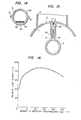
- Describing a first embodiment with reference to Figs. 4 and 5, the first embodiment includes a magnetron 1 equipped with a
magnetron antenna 2, awaveguide 3 having one end connected to the magnetron 1 and the other end connected to amicrowave feeding opening 5 formed in a wall of alight reflecting member 4 which is formed as a shell in the shape of a rotationally symmetrical cup or dome, and anenvelope 10 housing these components. In the wall of thewaveguide 3 are formed a plurality ofair holes 8. - The microwave discharge light source apparatus further includes a
spherical discharge bulb 6 of quartz glass which has no electrode and which has a sufficiently small size so as to make the light emissive portion thereof approximate a point light source. Thebulb 6. is filled with mercury as a discharge photoemissive substance and argon gas as a starter Noble gas and fixedly supported by thelight reflecting member 4. - The magnetron 1 is cooled by air flow provided by a
fan 7 supported by an upper wall of theenvelope 10 and the open end of the cup shapedreflection member 4 is covered by amesh plate 9 which is transparent to light but opaque to microwaves. Thelight reflecting member 4 forms together with themesh plate 9, aresonance cavity 49 which serves as a resonator when thebulb 6 is lit. - In operation, when electric power is supplied to the magnetron 1, the magnetron 1 radiates microwave energy through the
waveguide 3 and thefeeding opening 5 into themicrowave cavity 49. However, since thedischarge bulb 6 is not ignited immediately after the start of microwave oscillation, thecavity 49 is in the non-resonance state and only a microwave electromagnetic field is estabilished in thecavity 49 due to microwaves leaking from thefeeding opening 5. Then, the discharge of thebulb 6 is started by the electromagnetic field. When the discharge of thebulb 6 is started, thecavity 49 becomes resonant and a resonance electromagnetic field is established therein. Sufficient microwave energy to maintain the discharge of thedischarge bulb 6 is supplied by the resonance electromagnetic field. - Therefore, according to the invention, since the
microwave cavity 49 acts as a resonator, it is possible to inject a sufficient amount of microwave energy into the small spherical discharge bulb so that the efficiency of the device is increased over prior art constructions. Since the shape of thedischarge bulb 6 can be considered as a point light source, it is possible to dispose it at a position within thecavity 49 where the variation of microwave electromagnetic field distribution is negligible. Therefore, unevenness of the discharge in thedischarge bulb 6 is eliminated as is unevenness of light emission. Furthermore, since thelight reflecting member 4 has a rotationally symmetrical shape, the manufacture thereof is very easy so that, in determining the shape of thecavity 49 serving as a resonator, which is quite difficult to do analytically, it is easy to select an optimum size by changing the size thereof experimentally. - If the
mesh plate 9 is formed by, for example, etching a thin metal plate of a material such as a stainless steel plate having a thickness of 0.1 mm, the microwave loss thereof . is much smaller than a mesh plate made of metal wire because there is contact between metal portions. Therefore, the microwave energy can be more effectively converted into discharge energy and thus the light emission efficiency is considerably improved. - Further, as shown in Fig. 6, it is possible to form the
cavity 49 of the light reflecting member as a truncated pyramid. With this shape, a desired illumination distribution is obtained within the square area. In this case, the microwave electromagnetic field distribution is approximately in a square mode, while with the rotationally symmetrical cavity, the mode is approximately circular or cylindrical. - A second preferred embodiment will be described with reference to Fig. 7 in which the same or similar components as those in Fig. 6 are depicted by the same reference numerals. A light control member 11 including a lens is disposed below a
mesh plate 9 and acavity 43 is formed by a reflectingmember 41 having a center of curvature at the point at which thedischarge bulb 6 is disposed and awing portion 42 extending from thereflection member 41. An inner surface of thewing portion 42 is coated with graphite or provided with ananti-reflection layer 43 so that there is substantially no reflection from the inner surface of thewing portion 42. With this structure, in addition to the ease of cavity design, all of the light incident on the light control member 11 can be considered as emerging from thedischarge bulb 6. Thus, it is possible to control the illumination distribution by suitably setting the light collection characteristics of the light control member 11. - The light control member 11 may be of the light scattering type and, needless . to say, it is to be capable of regulating the illumination distribution.
- Further, this embodiment can be modified as shown in Fig. 8. In Fig. 8, the
light reflecting member 4 is rotationally symmetrical and has a peripheral portion inner surface which is provided with thelight absorption layer 43 which may be a coated layer of a material such as graphite. The light control member 11 may be fixedly secured byscrews 21 through an annular -mountingplate 20 to thelight reflecting member 4 with anannular spacer 22. With the modification of Fig. 8, the illumination distribution control of the illuminating area is performed in a similar manner to that in Fig. 7. In addition, since thecavity 49 can be formed as a resonance cavity by suitably determining the area where thelight absorption layer 43 is provided, the ease of design is much improved. - A third embodiment will be described with reference to Figs. 9 through 11 of which Fig. 9 is a schematic cross- sectional illustration thereof, Fig. 10 is an enlarged view of the cavity portion thereof and Fig. 11 is a further enlarged view of the cavity portion. In these figures, the same reference numerals used in Figs. 4 and 5 indicate the same or corresponding components as those used in Figs. 4 and 5. Here, the
-
discharge bulb 6 of quartz in the shape of a sphere is formed with a pair ofquartz protrusions 61 extending from anouter surface 62 thereof oppositely. As before, thebulb 6 is filled with mercury and argon gas. Thebulb 6 is further formed with aquartz tube 63 extending from theouter surface 62 thereof in which astart assisting member 64 in the form of a tantalum wire is encapsulated. - A
mesh plate 9 which is transparent to light but opaque. to microwave is fixed bybolts 15 between aflange portion 16 of thelight reflecting member 4 formed by bending the peripheral edge thereof and anannular press plate 17 corresponding in shape to theflange portion 16 which covers the open end of thelight reflecting member 4 to thereby define themicrowave cavity 49. - Free ends of the
protrusion 61 of thebulb 6 are inserted into inner ends ofsupporter cylinder 12 which is made of quartz. The outer ends of thesupporter cylinder 12 are inserted into cut-offsleeves 13 formed on the outer surface of thelight reflecting member 4 and supported thereby bystopper screws 14, respectively. The position of thebulb 6 supported in this way is determined such that when thebulb 6 is energized thecavity 49 becomes a resonator. - This arrangement can provide not only the same effects as provided by the first embodiment but also an effect that, due to the provision of the
start assisting member 64, the intensity of the electromagnetic field around the opposite ends of thestart assisting member 64 is quite high, as indicated by E in Fig. 11, and thus the electromagnetic field strength within thebulb 6 is higher than the discharge starting electromagnetic field strength even when the electromagnetic field strength within thecavity 49 immediately before the discharge starting of thebulb 6 is low thus assuring the ignition of thebulb 6 without increasing the microwave input energy. Further, thebulb 6 is easily detachable and positioning of the bulb 6-can be easily performed by merely adjusting the position of the supportingcylinder 12. - Furthermore, since the
start assisting member 64 is embedded in theexhausted tube 63 of dielectric material such as quartz and the breakdown voltage of the dielectric material in a vacuum is much higher than in air, the possibility of discharge outside of thebulb 6 is much reduced and the possibility of melting thestarting assisting member 64 is eliminated. The electromagnetic field distribution within thecavity 49 prior to the ignition of thebulb 6, i.e., in the state where impedance matching is not yet established, is most dense the near thefeeding opening 5. Therefore, if thestart assisting member 63 is positioned such that one end thereof is in the vicinity of thefeeding opening 5, it is possible to further strengthen the electromagnetic field within thebulb 6 to thereby cause the discharge starting to be accomplished easier. - Further, since the impedance of the
start assisting member 64 during stable discharge of thebulb 6 is negligible compared with the impedance of thebulb 6 itself, the existence of the start assisting member does not affect the stability of the operation of thebulb 6. - The length ℓ of the cut-off
sleeve 13 should be determined such that the leakage of microwaves from the cavity resonator is restricted to be at or below a level (1 mW/cm2) at which there is no safety problem. The power density (P) of leaked microwaves can be expressed by the following equation:

sleeve 13 in centimeters and Er is the specific dielectric constant of the supporting member. - Therefore, in order to make the leakage power P equal to or smaller than 1 mV/cm2, the length ℓ must be equal to or longer than:

- In the embodiment shown in Figs. 9 through 10, the
start assisting member 64 is embedded in thecylinder member 63 which protrudes from the outer surface of thedischarge bulb 6. Alternatively, it may be housed directly in thedischarge bulb 6 as shown in Fig. 12 or it may be covered by a dielectric material such as quartz to provide a reduced pressure atmosphere therefor so that themember 64 does not react with other materials filling thebulb 6 and then be housed in thebulb 6 as.shown in Fig. 13. Alternatively, a pair ofstart assisting members 64 may be used for this purpose as shown in Fig. 14. In Fig. 14, a pair ofstart assisting members 64 are encapsulated and coupled in series by a common evacuatedtube member 63 made of a dielectric material with opposing ends of themembers 64 being slightly separated.so that the electromagnetic field intensity is high around the space therebetween and thetube member 63 housed in thebulb 6. - Fig. 15 shows a modification of the
discharge bulb 6 in which the supporting thereof is somewhat simplified. In Fig. 15, thecylinder member 63 in which thestart assisting member 64 is positioned is used as a supporting portion thereof which is held by a corresponding supporting member provided around thefeeding opening 5 of thelight reflecting member 4. To this effect, athread 65 is formed on the outer surface of thecylinder member 63 and abulb support member 66 of the low loss dielectric material such as quartz glass having one end suitably fixed to thelight reflecting member 4 and the other end threaded cor- - respondingly to the
thread 65 of thecylinder member 63 is provided. Thedischarge bulb 6 is fixedly supported by screwing thecylinder member 63 into the thread of thebulb supporting member 66. In this case, there is no need of providing theprotrusions 61 and the cut-offsleeves 13 and therefore the manufacture of the device is considered quite simple. - In accordance with a fourth embodiment, in addition to mercury used in the preceding.embodiments, gallium is provided as a light emitting substance so that emitted light includes waves of the gallium atom spectrum of 403 nm and 417 nm as well as the mercury atom spectrum of 365 nm, 405 nm and 436 nm. The purpose of this embodiment is to make the apparatus of the present invention also applicable to an exposing light source for a diazo type photosensitive material which is sensitive to wavelengths of 403 nm and 417 nm. The
discharge bulb 6 and thelight reflecting member 4 used in this embodiment can be any of those of the preceding embodiments. - An actual device was assembled using the construction shown in Figs. 4 and 5 with the microwave output power of the magnetron 1 being 700 W and with the inner surface of the light reflecting 4 being completely covered by carbon black so as to eliminate the effects of reflection from the light reflecting member so that measurement could be made of only the direct light from the
bulb 6. The materials filling thebulb 6 were mercury, gallium and iodine as a halogen. A light output having wavelengths from 350 nm to 450 nm was measured for bulbs containing various amounts of these materials. - Fig. 16 shows a plot of relative light output on the ordinate for wavelengths from 350 nm to 450 nm with respect to the amount of.mercury encapsulated in the
bulb 6 on the abscissa. Here, the inner diameter of the spherical discharge bulb 6-was 30 mm and thebulb 6 also contained argon gas at 60 mmHG, 1 mg of gallium, 4 mg of mercury iodide and a variable amount of mercury. As will be clear from Fig. 16, when the amount of mercury is increased with the amounts of gallium and mercury iodide held constant, the light output reaches a maximum when the amount of mercury is about 100 mg. The arc is stable up to mercury amounts of about 150 mg and then the light emission becomes unstable with larger amounts. This may be considered due to the fact that when the amount of mercury is increased beyond 150 mg, the mercury vapor pressure in thedischarge bulb 6 becomes saturated and the excess amount of mercury is deposited on the inner wall of thedischarge bulb 6. This phenomenon can also be observed when the amount of mercury is varied with the amounts of gallium and mercury iodine being other constant values. - Fig. 17 shows a plot of relative optical output of the
discharge bulb 6 in a wavelength range from 350 nm to 450 nm with the amount of mercury iodide on the abscissa for a case where the spherical bulb has an inner diameter of 30 mm and contains argon gas at 60 mmHg, 60 mg of mercury, 0.5 mg of gallium and various amounts of mercury iodide. As is clear from Fig. 17, the light output of thebulb 6 increases substantially with increased amounts of mercury iodide reaching a maximum when the amount of mercury iodide is about 2 mg, i.e., when the atom ratio of gallium to iodide is around 1:1.2. With a further increase in the amount of mercury iodide, the output decreases gradually. This tendency can also be observed when the amount of mercury iodide is varied while the amounts of mercury and gallium are other constant values. It has been observed that the maximum light output is obtained when the gallium to mercury iodide ratio is 1;4, i.e., for a gallium atom to iodide atom ratio of about 1:1.2. - Fig. 18 shows plots:of relative light outputs in a wavelength range from 350 nm to 450 nm of three
spherical discharge bulbs 6 which have an inner diameter of 30 mm and which contain argon gas at 60 mmHg and a variable amount of a mixture of gallium and mercury iodide with fixed ratio of 1:4 together with mercury in amounts of 60 mg, 80 mg and 150 mg. As is clear from Fig. 18, regardless of the amount of mercury, the light output increases with an increased amount of the mixture and becomes a maximum with the amount of gallium at about 0.5 mg to about 2.0 mg and then decreases with a further increase of gallium. When the amount of gallium is increased beyond 2.5 mg, i.e., when the amount of mercury iodide is greater than 10 mg, the arc becomes astable even when there is no residual mercury. This may be considered as due to the fact that iodine in the arc affects the latter adversely. This is confirmed by the fact that when only the amount of gallium is increased with the amount of mercury iodide restricted to be 10 mg or less, there is no turbulence of the arc while gallium is deposited on a portion of the inner wall of the bulb in operation. - It will be clear from a consideration of Embodiments 4-1 through 4-3 that in order to obtain an intense light output in a wavelength range of from 350 nm to 450 nm by using microwave excitation, a non-electrode discharge light source having a spherical discharge bulb having an inner diameter of 30 mm with amounts of mercury, gallium and mercury iodide encapsulated in the bulb of 20 mg to 170 mg, 1510 mg, 0.1 mg or more and 0.5 mg to 15 mg, respectively, should be used. These values can be represented in gram atomic weight per unit inner volume of the bulb as 7 x 10 -6 60 x 10-6, 1 x 10 -7 or more and 1.5 x 10 to 50 x 10-7, respectively. In this case, mercury iodide includes mercury of 0.75 x 10⁻⁷ to 25 x 10-7 gram atomic weight/cc. However, since the amount of mercury contained in the mercury iodide is very small in comparison with the required amount of mercury, that amount may be considered negligible. It should be noted again that, with these substances, except for gallium, with less than the specified values, it is impossible to obtain a required light output and in, the specified wavelength range with these substances, except for gallium if greater quantities are used, the light output decreases and the arc becomes astable. As to the amount of gallium, since it does not become halogenized gallium and the saturating vapor.pressure of metal gallium at the temperature of the inner wall of the operating bulb is low, metal gallium which is not converted into gallium iodide is deposited on the bulb inner wall. However, since this metal gallium does not affect the arc adversely, there is no need of defining of an upper limit on the amount thereof.
- Although the above Embodiments 4-1 to 4-3 relate specifically to a spherical bulb having an inner diameter of 30 mm, substantially the same results can be obtained by using a bulb having an inner diameter of 20 mm to 50 mm. However, with a bulb having an inner diameter smaller than 20 mm and for a microwave input of 700 w, the bulb tends to break within a short time due to the high temperature even if the amount of cooling air is increased. On the contrary, with a bulb having an inner diameter larger than 55 mm, the temperature of the bulb wall will be too cool even if the cooling air'supply is stopped and thus it is impossible to obtain the necessary vapor pressures of the substances encapsulated in the bulb in operation resulting in a reduced light output. Therefore, in order to obtain a required light output within the desired wavelength range, it is preferable to select the surface area of the bulb per unit microwave input within the range from 1.5 mm2/V to 15
mm 2 /W. This range is also preferable for Embodiments 1 to 3 in which only mercury is used as the discharge emissive substance. - Fig. 19 shows plots of time required to stabilize the light emission of
spherical bulbs 6 having an inner diameter of 30 mm for different wall thicknesses, and hence total bulb weights, for bulbs containing argon at 60 mmHg, 80 mg of mercury, 1 mg/gallium, and 4 mg of mercury iodide. The graph of Fig. 19 also contains similar plots of the time required to stabilize the light emission of bulbs having inner diameters of 25 mm and 40 mm, respectively, with each bulb containing suitable amounts of argon, mercury, gallium and mercury iodide in the same ratio as the 30 mm diameter bulb to estabilish the same physical and chemical conditions within the bulbs for comparison purposes. In this embodiment, the stabilizing time required to stabilize the light output is defined as the time until the light output reaches 80% of the light output after the bulb is completely stabilized. - As is clear from Fig. 19, the stabilizing time increases substantially linearly with increases of bulb weight beyond about 4 g, while for weights of less than 4 g, the effect of shortening the stabilizing time is not substantial.
- With a bulb weight greater than 20 g, the stabilizing time becomes longer than 1 minute and thus the merit of a microwave discharge light source apparatus having a short stabilizing time disappears. It should be note.d that the data shown in Fig. 19 was obtained by a magnetron having a microwave output of 700 W. Since the stabilizing time depends mainly upon the correlation between the microwave output and the thermal capacity of the transparent quartz glass forming the outer wall of the bulb, a larger the microwave input to the bulb results in a shorter stabilizing time which is proportional to the thermal capacity of the quartz glass forming the outer wall of the
bulb 6. Therefore, in order to restrict the stabilizing time within.desirable limits, the weight of the bulb 6-for a given microwave input thereto should be set within predetermined limits. For example, a stabilizing time shorter than 1 minute can be obtained with abulb 6 having a weight of about 3.0 x 10⁻² g/W or lighter. This is also applicable to Embodiments 1-3 which are bulbs containing only mercury as emission substance. - A specific circuit of a power source for the magnetron 1 used in the Embodiments 1 to 4 will now be described with reference to Fig. 20.
- In Fig. 20, a transformer T has a primary winding 1P connected across an A-C supply E and a secondary winding IS is connected in parallel with a series circuit of a capacitor C11 arid a diode D11. A series circuit of a capacitor C12 and a diode D12 is connected in parallelwiththe series connection of the capacitor C11 and diode D11. The capacitors C11 and C12 and diodes D11 and D12 form a full wave voltage doubler rectifier whose output voltage is applied to an anode of.the magnetron 1. The transformer T has a further secondary.winding 2S having terminals connected to a cathode of the magnetron 1.
- By using the full-wave voltage doubler rectifier circuit shown in Fig. 20, it is possible to restrict the rest period of microwaves to 5 msec or shorter economically. Further, if a leakage transfomer is used as the transformer T, a microwave output having a waveform shown in Fig. 21 can be obtained. In Fig. 21, a
time period 181 is a microwave generating period and atime period 191 is the microwave rest period. When thisrest period 191 is on the order of 1 msec, the ionized gas does not extinguish so that a discharge can be restarted immediately thereafter. Thus, there is no termination of discharge so long as the rest period is sufficiently short. - Since with the circuit of Fig. 20 the rest period can be made 5 msec or shorter by using a full-wave voltage doubler rectifier and a leakage transformer for applying the anode voltage to the diode of the magnetron 1, there is no termination of discharge caused by a longer rest period..This is another important effect of the present invention in comparison with a conventional power source for a magnetron 1 using a half-wave voltage doubler rectifier in'which the rest period is usually 8 to 10 msec and for which there is a disadvantage that the discharge may stop after a period of several to several tens of seconds after discharge initiation depending on the types of metals encapsulated in the
discharge bulb 6. This phenomenon of the conventional power supply can be considered to be due to the fact that since the metals encapsulated in the bulb are vaporized and the metal gas atom density in the bulb after the discharge commences is high so that the amount of energy derived from the microwave energy injected into the bulb before collision of electrons with atoms is small, the ionization probability is lowered below a level necessary to maintain the discharge. Further, the prior art power supply used to drive the magnetron to thereby cause it generate microwaves continuously is expensive. As to the microwave generator itself, there is a disadvantage that if it:first generates microwaves continuously and then the operation thereof is shifted to the sink region, it is very difficult to recover the normal operation. There is no such defect in the apparatus of the invention. - Although the circuit of Fig. 20 has been described as being used with a single magnetron 1, it is possible to use a pair of magnetrons for this purpose. In such a case, the magnetrons may be driven by power supplies having half-wave voltage doubler rectifies shifted in phase by 180° with respect to each other.
- In the microwave discharge light source apparatus of any of Embodiments 1 to 4, it is advantageous to further shorten the stabilizing time from the discharge initiation of the
discharge bulb 6 through the metal gas discharge to the stabilized discharge state. The stabilizing time depends upon the evaporation rate of the metal encapsulated in thebulb 6 and that rate, in turn, depends upon the rate of temperature increase of the inner wall of thebulb 6. An increase of the temperature increase rate can be brought about by a larger discharge energy, i.e., microwave energy. - In view of these facts, as well as the operational characteristics of the magnetrons, it has been found that a shortening of the. stabilizing time can be achieved by suitably selecting the length of the
waveguide 3. - In general, the operation of the magnetron can be represented by a Rieke diagram on an impedance chart as shown in Fig. 22. In Fig. 22, the distance from the center of the chart and the angular position respectively represent the microwave reflection coefficient o and the phase. Lines A to F are equi-output power lines of:the oscillation output of the magnetron with the line A corresponding to the highest output power line and with the output gradually decreasing toward the line F. a indicates the sink region of the magnetron where the oscillation thereof becomes abnormal.
- Fig. 23 shows an example of the impedance of the cavity 4-after the
discharge bulb 6 is ignited. The impedance of the cavity immediately after the bulb is ignited is indicated by a .point LA. After the ignition, the impedance of thecavity 4 varies with variations of the discharge state due to vaporization of the metals in the bulb becoming constant in the stable state. By matching the impedance, i.e., regulating the resonance frequency of the cavity and the dimensions of the feeding opening such that the characteristic impedance is at the center of the impedance chart, the impedance varies from the point LA through L to the center of the chart. - As mentioned above, the output power of the magnetron 1 is largest at the side of the sink region. Therefore, by making the load impedance (here, the cavity impedance) seen from the
magnetron 2 larger at the sink side, a greater amount of microwave energy can be provided. When thewaveguide 3 is connected to thecavity 4, the impedance seen from the free end of thewaveguide 3 becomes equal to the cavity impedance rotated around the center of the impedance chart by an angle corresponding to the length of thewaveguide 3. Therefore, in order to position the line Ll in Fig. 23 at the sink side in Fig. 22 by rotation, a line L2 may be obtained by rotating the line L1 by, for example, 0.25 λg, where λg is the wavelength of thewaveguide 3. That is, the length of thewaveguide 3 may be 0.25 λg. As is clear from Fig. 23, the same effect can be obtained by selecting the length of the waveguide to be 0.25 Xg + n x 0.5 λg where n is an integer because 0.5 λg corresponds to one complete rotation of the line L1. - Accordingly, in this example, by varying the length of the
waveguide 3 between thecavity 4 and the magnetron 1, the load impedance for the magnetron 1 varies along the line L2 so that the magnetron output power follows the lines A-B shown in Fig. 22 resulting in a larger output power. Therefore, the stabilizing time can be shortened. - The above description relates to the case where the cavity impedance is moved from the point LA along the line L1. However, the same is also applicable to other impedance conditions of the cavity which may depend on the shape of the cavity, the position of the discharge bulb therein and the content of the bulb, etc. In any case, the length of the waveguide is to be selected so as to meet these conditions. It should be noted that, generally, the magnetron output is large where the operating point thereof is at a position within a quarter wavelength phase width of the waveguide on the sink side and therefore the length of the waveguide can be determined by the latter condition.
- In the microwave generated plasma light source apparatus described with reference to Embodiments 1 to 6, it is possible to use a
small discharge bulb 6 and thus the microwave power per unit surface area of thebulb 6 can be made large even if the microwave power supplied thereto is relatively small resulting in a high light emission efficiency. For example, a magnetron having a small output,such as magnetron used for an electronic cooking range for home use, may be utilized for this purpose. - As mentioned hereinbefore, the microwave generated plasma light source apparatus according to the present invention includes a microwave generator, a microwave cavity serving as a resonance cavity having a light reflecting member and a member transparent to light and but opaque to microwaves, a waveguide for guiding microwaves generated by the microwave generator to a feeding opening of the cavity, and a small non-electrode discharge bulb which is disposed in a position in the cavity such that the cavity operates as a resonant cavity at least when the bulb is lit with the bulb being sufficiently small that it can be approximated as a point light source and discharge light emissive substances therein are encapsulated therein. With this construction, it is possible to supply microwaves to the bulb efficiently, the optical design is facilitated and a illumination distribution is achieved or another desirea illumination distribution can be provided.
- Particularly, if gallium is added as 'the discharge emissive substance to the discharge bulb, the light emission characteristics of the light source apparatus are suitable for use in photographic plate making which requires a highly uniform illumination distribution in a specific area.
- The light source apparatus of the invention can be used also as a light source such as a spotlight source, which requires a small light source of high output, by modifying the shape of the light reflecting member constituting the microwave resonance cavity.
Claims (18)
Applications Claiming Priority (2)
| Application Number | Priority Date | Filing Date | Title |
|---|---|---|---|
| JP29911/80 | 1980-03-10 | ||
| JP2991180A JPS56126250A (en) | 1980-03-10 | 1980-03-10 | Light source device of micro wave discharge |
Publications (2)
| Publication Number | Publication Date |
|---|---|
| EP0035898A1 true EP0035898A1 (en) | 1981-09-16 |
| EP0035898B1 EP0035898B1 (en) | 1989-06-14 |
Family
ID=12289166
Family Applications (1)
| Application Number | Title | Priority Date | Filing Date |
|---|---|---|---|
| EP81300965A Expired EP0035898B1 (en) | 1980-03-10 | 1981-03-09 | Microwave generated plasma light source apparatus |
Country Status (7)
| Country | Link |
|---|---|
| US (2) | US4498029A (en) |
| EP (1) | EP0035898B1 (en) |
| JP (1) | JPS56126250A (en) |
| CA (1) | CA1197549A (en) |
| DE (1) | DE3177071D1 (en) |
| HK (1) | HK10790A (en) |
| SG (1) | SG490G (en) |
Cited By (9)
| Publication number | Priority date | Publication date | Assignee | Title |
|---|---|---|---|---|
| EP0153745A2 (en) * | 1984-03-02 | 1985-09-04 | Mitsubishi Denki Kabushiki Kaisha | Microwave discharge light source apparatus |
| EP0840354A2 (en) * | 1996-11-01 | 1998-05-06 | Matsushita Electric Industrial Co., Ltd. | High frequency discharge energy supply means and high frequency electrodeless discharge lamp device |
| EP0890784A3 (en) * | 1997-07-11 | 1999-09-08 | Gebr. Berchtold GmbH & Co. | Surgical lamp |
| WO2002011181A1 (en) * | 2000-07-31 | 2002-02-07 | Luxim Corporation | Plasma lamp with dielectric waveguide |
| US6351087B1 (en) | 1998-07-15 | 2002-02-26 | Matsushita Electronics Corporation | Microwave electrodeless discharge lamp apparatus |
| EP1304724A2 (en) * | 2001-09-27 | 2003-04-23 | Lg Electronics Inc. | Bulb with reflector and electrodeless discharge lamp using same |
| KR100430007B1 (en) * | 2002-04-12 | 2004-05-03 | 엘지전자 주식회사 | Feeder structure for plasma lighting system |
| US7372209B2 (en) | 2000-07-31 | 2008-05-13 | Luxim Corporation | Microwave energized plasma lamp with dielectric waveguide |
| WO2014161670A1 (en) * | 2013-04-05 | 2014-10-09 | Cooper Crouse-Hinds Gmbh | Lamp |
Families Citing this family (96)
| Publication number | Priority date | Publication date | Assignee | Title |
|---|---|---|---|---|
| US4507587A (en) * | 1982-05-24 | 1985-03-26 | Fusion Systems Corporation | Microwave generated electrodeless lamp for producing bright output |
| US4749915A (en) * | 1982-05-24 | 1988-06-07 | Fusion Systems Corporation | Microwave powered electrodeless light source utilizing de-coupled modes |
| US4485332A (en) * | 1982-05-24 | 1984-11-27 | Fusion Systems Corporation | Method & apparatus for cooling electrodeless lamps |
| US4954755A (en) * | 1982-05-24 | 1990-09-04 | Fusion Systems Corporation | Electrodeless lamp having hybrid cavity |
| JPS60178966U (en) * | 1984-05-08 | 1985-11-28 | 三菱電機株式会社 | Microwave discharge light source device |
| JPS6229097A (en) * | 1985-07-31 | 1987-02-07 | アールディエス株式会社 | Microwave discharge light source unit |
| JPS61179055A (en) * | 1986-01-08 | 1986-08-11 | Mitsubishi Electric Corp | Microwave discharge light source device |
| US4933602A (en) * | 1987-03-11 | 1990-06-12 | Hitachi, Ltd. | Apparatus for generating light by utilizing microwave |
| JPH07111918B2 (en) * | 1987-07-28 | 1995-11-29 | 三菱電機株式会社 | Microwave discharge light source device |
| JPH0665178B2 (en) * | 1988-02-23 | 1994-08-22 | 株式会社オーク製作所 | Annular electrodeless discharge light source device and lighting method thereof |
| US4887192A (en) * | 1988-11-04 | 1989-12-12 | Fusion Systems Corporation | Electrodeless lamp having compound resonant structure |
| JPH02189805A (en) * | 1989-01-17 | 1990-07-25 | Ushio Inc | Microwave excitation type electrodeless light emitting device |
| US5022756A (en) * | 1989-11-03 | 1991-06-11 | Hewlett-Packard Company | Method and apparatus for spectrochemical analysis having maximum repeatability |
| US5142198A (en) * | 1989-12-21 | 1992-08-25 | Applied Science And Technology, Inc. | Microwave reactive gas discharge device |
| US5117312A (en) * | 1991-01-04 | 1992-05-26 | Fusion Systems Corporation | Apparatus including concave reflectors and a line of optical fibers |
| US5241246A (en) * | 1991-09-10 | 1993-08-31 | Gte Laboratories Incorporated | End cup applicators for high frequency electrodeless lamps |
| US5504391A (en) * | 1992-01-29 | 1996-04-02 | Fusion Systems Corporation | Excimer lamp with high pressure fill |
| US5594303A (en) * | 1995-03-09 | 1997-01-14 | Fusion Lighting, Inc. | Apparatus for exciting an electrodeless lamp with an increasing electric field intensity |
| US5786667A (en) * | 1996-08-09 | 1998-07-28 | Fusion Lighting, Inc. | Electrodeless lamp using separate microwave energy resonance modes for ignition and operation |
| JPH10321039A (en) * | 1997-05-15 | 1998-12-04 | Matsushita Electron Corp | Microwave discharge lamp device |
| US6157141A (en) * | 1998-05-05 | 2000-12-05 | Osram Sylvania Inc. | Blue light electrodeless high intensity discharge lamp system |
| US6674407B1 (en) * | 1999-05-28 | 2004-01-06 | David Lowe | Laser beam frequency collection device |
| US6468090B2 (en) | 1999-09-15 | 2002-10-22 | Fci Americas Technology, Inc. | Low inductance power connector and method of reducing inductance in an electrical connector |
| JP4901041B2 (en) * | 1999-09-20 | 2012-03-21 | ノードソン コーポレーション | Apparatus and method for generating ultraviolet light |
| JP3620371B2 (en) | 1999-10-01 | 2005-02-16 | ウシオ電機株式会社 | High frequency excitation point light source lamp device |
| US6351070B1 (en) | 1999-12-28 | 2002-02-26 | Fusion Uv Systems, Inc. | Lamp with self-constricting plasma light source |
| JP3580205B2 (en) * | 2000-01-18 | 2004-10-20 | ウシオ電機株式会社 | Electromagnetic energy excitation point light source lamp device |
| EP1279187B1 (en) | 2000-04-26 | 2004-07-14 | Cornell Research Foundation, Inc. | Lamp utilizing fiber for enhanced starting field |
| US7429818B2 (en) * | 2000-07-31 | 2008-09-30 | Luxim Corporation | Plasma lamp with bulb and lamp chamber |
| AU2002239243A1 (en) * | 2000-11-13 | 2002-06-03 | Fusion Lighting, Inc. | Sealed microwave lamp and light distribution system |
| KR100396772B1 (en) * | 2001-02-02 | 2003-09-03 | 엘지전자 주식회사 | Microwave lighting system |
| US6445138B1 (en) | 2001-03-14 | 2002-09-03 | Fusion Uv Systems, Inc. | Microwave powered lamp with improved cooling system |
| GB0120993D0 (en) * | 2001-08-30 | 2001-10-24 | Quay Technologies | Pulsed UV light source |
| US6897615B2 (en) * | 2001-11-01 | 2005-05-24 | Axcelis Technologies, Inc. | Plasma process and apparatus |
| KR100442397B1 (en) * | 2002-01-17 | 2004-07-30 | 엘지전자 주식회사 | Structure for exciting discharge in plasma lighting system |
| KR100451358B1 (en) | 2002-03-04 | 2004-10-06 | 주식회사 엘지이아이 | Power supply for lighting apparatus using microwave |
| TWI231763B (en) * | 2002-11-08 | 2005-05-01 | Matsushita Electric Works Ltd | Sterilizer |
| US20040165391A1 (en) * | 2003-02-20 | 2004-08-26 | Aetek Uv Systems, Inc. | Method and apparatus for linear lamp irradiance correction |
| KR100531908B1 (en) * | 2003-09-03 | 2005-11-29 | 엘지전자 주식회사 | Concentration apparatus for micro wave in plasma lighting system |
| KR100556782B1 (en) * | 2003-12-06 | 2006-03-10 | 엘지전자 주식회사 | Plasma lamp system |
| US7038383B2 (en) * | 2004-09-27 | 2006-05-02 | Osram Sylvania Inc. | Ignition aid for high intensity discharge lamp |
| US7187131B2 (en) * | 2004-12-14 | 2007-03-06 | Osram Sylvania Inc. | Discharge lamp with internal starting electrode |
| US7906910B2 (en) * | 2005-10-27 | 2011-03-15 | Luxim Corporation | Plasma lamp with conductive material positioned relative to RF feed |
| US7791280B2 (en) * | 2005-10-27 | 2010-09-07 | Luxim Corporation | Plasma lamp using a shaped waveguide body |
| US7638951B2 (en) | 2005-10-27 | 2009-12-29 | Luxim Corporation | Plasma lamp with stable feedback amplification and method therefor |
| US7791278B2 (en) | 2005-10-27 | 2010-09-07 | Luxim Corporation | High brightness plasma lamp |
| US8022607B2 (en) * | 2005-10-27 | 2011-09-20 | Luxim Corporation | Plasma lamp with small power coupling surface |
| US7994721B2 (en) * | 2005-10-27 | 2011-08-09 | Luxim Corporation | Plasma lamp and methods using a waveguide body and protruding bulb |
| US7855511B2 (en) * | 2005-10-27 | 2010-12-21 | Luxim Corporation | Plasma lamp with phase control |
| US7701143B2 (en) * | 2005-10-27 | 2010-04-20 | Luxim Corporation | Plasma lamp with compact waveguide |
| WO2007079496A2 (en) | 2006-01-04 | 2007-07-12 | Luxim Corporation | Plasma lamp with field-concentrating antenna |
| US7435982B2 (en) * | 2006-03-31 | 2008-10-14 | Energetiq Technology, Inc. | Laser-driven light source |
| US20110043123A1 (en) * | 2006-10-16 | 2011-02-24 | Richard Gilliard | Electrodeless plasma lamp and fill |
| WO2008048600A2 (en) * | 2006-10-16 | 2008-04-24 | Luxim Corporation | Modulated light source systems and methods |
| US20110043111A1 (en) * | 2006-10-16 | 2011-02-24 | Gregg Hollingsworth | Rf feed configurations and assembly for plasma lamp |
| US20100253231A1 (en) * | 2006-10-16 | 2010-10-07 | Devincentis Marc | Electrodeless plasma lamp systems and methods |
| WO2008127367A2 (en) * | 2006-10-16 | 2008-10-23 | Luxim Corporation | Discharge lamp using spread spectrum |
| US8143801B2 (en) * | 2006-10-20 | 2012-03-27 | Luxim Corporation | Electrodeless lamps and methods |
| WO2008051877A2 (en) * | 2006-10-20 | 2008-05-02 | Luxim Corporation | Electrodeless lamps and methods |
| US20080211971A1 (en) * | 2007-01-08 | 2008-09-04 | Luxim Corporation | Color balancing systems and methods |
| US8159136B2 (en) * | 2007-02-07 | 2012-04-17 | Luxim Corporation | Frequency tunable resonant cavity for use with an electrodeless plasma lamp |
| US8084955B2 (en) * | 2007-07-23 | 2011-12-27 | Luxim Corporation | Systems and methods for improved startup and control of electrodeless plasma lamp using current feedback |
| WO2009014709A1 (en) * | 2007-07-23 | 2009-01-29 | Luxim Corporation | Reducing arcing in electrodeless lamps |
| US20090167201A1 (en) * | 2007-11-07 | 2009-07-02 | Luxim Corporation. | Light source and methods for microscopy and endoscopy |
| MX2010001511A (en) * | 2007-11-16 | 2010-03-15 | Ceravision Ltd | Light source. |
| US8179046B2 (en) * | 2008-05-20 | 2012-05-15 | Nordson Corporation | Ultraviolet lamp system with cooling air filter |
| EP2340691A4 (en) * | 2008-09-18 | 2015-09-16 | Luxim Corp | Low frequency electrodeless plasma lamp |
| WO2010033780A1 (en) * | 2008-09-18 | 2010-03-25 | Luxim Corporation | Electrodeless plasma lamp and drive circuit |
| US8304994B2 (en) * | 2008-10-09 | 2012-11-06 | Luxim Corporation | Light collection system for an electrodeless RF plasma lamp |
| US20100123396A1 (en) * | 2008-10-09 | 2010-05-20 | Luxim Corporation | Replaceable lamp bodies for electrodeless plasma lamps |
| US20100102724A1 (en) * | 2008-10-21 | 2010-04-29 | Luxim Corporation | Method of constructing ceramic body electrodeless lamps |
| US20100165306A1 (en) * | 2008-12-31 | 2010-07-01 | Luxmi Corporation | Beam projection systems and methods |
| EP2386110A4 (en) * | 2009-01-06 | 2013-01-23 | Luxim Corp | Low frequency electrodeless plasma lamp |
| US8282435B2 (en) * | 2009-03-09 | 2012-10-09 | Topanga Technologies, Inc. | Method and system for replacing a plasma lamp from a resonator assembly |
| GB0907947D0 (en) * | 2009-05-08 | 2009-06-24 | Ceravision Ltd | Light source |
| US8629616B2 (en) | 2011-01-11 | 2014-01-14 | Topanga Technologies, Inc. | Arc tube device and stem structure for electrodeless plasma lamp |
| US9177779B1 (en) | 2009-06-15 | 2015-11-03 | Topanga Usa, Inc. | Low profile electrodeless lamps with an externally-grounded probe |
| US8188662B2 (en) | 2009-12-18 | 2012-05-29 | Luxim Corporation | Plasma lamp having tunable frequency dielectric waveguide with stabilized permittivity |
| EP2534672B1 (en) | 2010-02-09 | 2016-06-01 | Energetiq Technology Inc. | Laser-driven light source |
| JP2011175748A (en) * | 2010-02-23 | 2011-09-08 | Seiko Epson Corp | Light source device, and projection type display apparatus |
| US8269190B2 (en) | 2010-09-10 | 2012-09-18 | Severn Trent Water Purification, Inc. | Method and system for achieving optimal UV water disinfection |
| US8860323B2 (en) | 2010-09-30 | 2014-10-14 | Luxim Corporation | Plasma lamp with lumped components |
| GB201206556D0 (en) * | 2012-04-13 | 2012-05-30 | Ceravision Ltd | Light source |
| US9099291B2 (en) | 2013-06-03 | 2015-08-04 | Topanga Usa, Inc. | Impedance tuning of an electrode-less plasma lamp |
| IL234729B (en) | 2013-09-20 | 2021-02-28 | Asml Netherlands Bv | Laser-operated light source and method including mode scrambler |
| IL234727B (en) | 2013-09-20 | 2020-09-30 | Asml Netherlands Bv | Laser-operated light source in an optical system corrected for aberrations and method of designing the optical system |
| US9392752B2 (en) | 2014-05-13 | 2016-07-19 | Topanga Usa, Inc. | Plasma growth lamp for horticulture |
| US10186416B2 (en) | 2014-05-15 | 2019-01-22 | Excelitas Technologies Corp. | Apparatus and a method for operating a variable pressure sealed beam lamp |
| WO2015175760A1 (en) | 2014-05-15 | 2015-11-19 | Excelitas Technologies Corp. | Laser driven sealed beam lamp |
| US9741553B2 (en) | 2014-05-15 | 2017-08-22 | Excelitas Technologies Corp. | Elliptical and dual parabolic laser driven sealed beam lamps |
| CN104064441B (en) * | 2014-06-12 | 2016-05-04 | 单家芳 | For the microwave cavity of plasma source |
| US10057973B2 (en) | 2015-05-14 | 2018-08-21 | Excelitas Technologies Corp. | Electrodeless single low power CW laser driven plasma lamp |
| US9576785B2 (en) | 2015-05-14 | 2017-02-21 | Excelitas Technologies Corp. | Electrodeless single CW laser driven xenon lamp |
| US10008378B2 (en) | 2015-05-14 | 2018-06-26 | Excelitas Technologies Corp. | Laser driven sealed beam lamp with improved stability |
| KR101880747B1 (en) * | 2017-08-30 | 2018-07-20 | 주식회사 말타니 | Microwave Discharge Lamp |
| US10109473B1 (en) | 2018-01-26 | 2018-10-23 | Excelitas Technologies Corp. | Mechanically sealed tube for laser sustained plasma lamp and production method for same |
Citations (3)
| Publication number | Priority date | Publication date | Assignee | Title |
|---|---|---|---|---|
| US3787705A (en) * | 1972-04-28 | 1974-01-22 | Gen Electric | Microwave-excited light emitting device |
| US4001632A (en) * | 1975-04-21 | 1977-01-04 | Gte Laboratories Incorporated | High frequency excited electrodeless light source |
| US4189661A (en) * | 1978-11-13 | 1980-02-19 | Gte Laboratories Incorporated | Electrodeless fluorescent light source |
Family Cites Families (10)
| Publication number | Priority date | Publication date | Assignee | Title |
|---|---|---|---|---|
| US3374393A (en) * | 1965-02-12 | 1968-03-19 | Melpar Inc | Intense incoherent light source obtained by quenching the higher excited states and concentrating the energy on the lower states |
| US3541372A (en) * | 1966-12-28 | 1970-11-17 | Hitachi Ltd | Microwave plasma light source |
| US3648100A (en) * | 1969-03-24 | 1972-03-07 | Westinghouse Electric Corp | Electrodeless pulsed illuminator |
| US3641389A (en) * | 1969-11-05 | 1972-02-08 | Varian Associates | High-power microwave excited plasma discharge lamp |
| US3609448A (en) * | 1970-01-14 | 1971-09-28 | Varian Associates | High-power plasma generator employed as a source of light flux at atmospheric pressure |
| US3911318A (en) * | 1972-03-29 | 1975-10-07 | Fusion Systems Corp | Method and apparatus for generating electromagnetic radiation |
| US3872349A (en) * | 1973-03-29 | 1975-03-18 | Fusion Systems Corp | Apparatus and method for generating radiation |
| US4042850A (en) * | 1976-03-17 | 1977-08-16 | Fusion Systems Corporation | Microwave generated radiation apparatus |
| JPS581511B2 (en) * | 1977-12-15 | 1983-01-11 | 三菱電機株式会社 | electrodeless fluorescent lamp |
| US4175246A (en) * | 1978-02-27 | 1979-11-20 | Advance Transformer Company | Energizing circuit for magnetron using dual transformer secondaries |
-
1980
- 1980-03-10 JP JP2991180A patent/JPS56126250A/en active Pending
-
1981
- 1981-03-09 DE DE8181300965T patent/DE3177071D1/en not_active Expired
- 1981-03-09 EP EP81300965A patent/EP0035898B1/en not_active Expired
- 1981-03-10 CA CA000372644A patent/CA1197549A/en not_active Expired
-
1984
- 1984-07-02 US US06/625,565 patent/US4498029A/en not_active Ceased
-
1986
- 1986-11-20 US US06/932,416 patent/USRE32626E/en not_active Expired - Lifetime
-
1990
- 1990-01-02 SG SG490A patent/SG490G/en unknown
- 1990-02-08 HK HK10790A patent/HK10790A/en unknown
Patent Citations (3)
| Publication number | Priority date | Publication date | Assignee | Title |
|---|---|---|---|---|
| US3787705A (en) * | 1972-04-28 | 1974-01-22 | Gen Electric | Microwave-excited light emitting device |
| US4001632A (en) * | 1975-04-21 | 1977-01-04 | Gte Laboratories Incorporated | High frequency excited electrodeless light source |
| US4189661A (en) * | 1978-11-13 | 1980-02-19 | Gte Laboratories Incorporated | Electrodeless fluorescent light source |
Non-Patent Citations (1)
| Title |
|---|
| SOVIET INVENTIONS ILLUSTRATED, Section R, Week B 30, 5. September 1979, DERWENT PUBLICATIONS LTD., London, R 45 * |
Cited By (20)
| Publication number | Priority date | Publication date | Assignee | Title |
|---|---|---|---|---|
| EP0153745A3 (en) * | 1984-03-02 | 1986-12-03 | Mitsubishi Denki Kabushiki Kaisha | Microwave discharge light source apparatus |
| EP0153745A2 (en) * | 1984-03-02 | 1985-09-04 | Mitsubishi Denki Kabushiki Kaisha | Microwave discharge light source apparatus |
| EP0840354A2 (en) * | 1996-11-01 | 1998-05-06 | Matsushita Electric Industrial Co., Ltd. | High frequency discharge energy supply means and high frequency electrodeless discharge lamp device |
| EP0840354A3 (en) * | 1996-11-01 | 1998-09-23 | Matsushita Electric Industrial Co., Ltd. | High frequency discharge energy supply means and high frequency electrodeless discharge lamp device |
| EP0890784A3 (en) * | 1997-07-11 | 1999-09-08 | Gebr. Berchtold GmbH & Co. | Surgical lamp |
| US6351087B1 (en) | 1998-07-15 | 2002-02-26 | Matsushita Electronics Corporation | Microwave electrodeless discharge lamp apparatus |
| US8110988B2 (en) | 2000-07-31 | 2012-02-07 | Luxim Corporation | Plasma lamp with dielectric waveguide |
| US8125153B2 (en) | 2000-07-31 | 2012-02-28 | Luxim Corporation | Microwave energized plasma lamp with dielectric waveguide |
| US8203272B2 (en) | 2000-07-31 | 2012-06-19 | Luxim Corporation | Plasma lamp with dielectric waveguide integrated with transparent bulb |
| US6737809B2 (en) | 2000-07-31 | 2004-05-18 | Luxim Corporation | Plasma lamp with dielectric waveguide |
| WO2002011181A1 (en) * | 2000-07-31 | 2002-02-07 | Luxim Corporation | Plasma lamp with dielectric waveguide |
| US7372209B2 (en) | 2000-07-31 | 2008-05-13 | Luxim Corporation | Microwave energized plasma lamp with dielectric waveguide |
| EP2133905A1 (en) * | 2000-07-31 | 2009-12-16 | Ceravision Limited | Plasma lamp with dielectric waveguide |
| US7919923B2 (en) | 2000-07-31 | 2011-04-05 | Luxim Corporation | Plasma lamp with dielectric waveguide |
| US7940007B2 (en) | 2000-07-31 | 2011-05-10 | Luxim Corporation | Plasma lamp with dielectric waveguide integrated with transparent bulb |
| EP1304724A3 (en) * | 2001-09-27 | 2005-10-26 | Lg Electronics Inc. | Bulb with reflector and electrodeless discharge lamp using same |
| EP1304724A2 (en) * | 2001-09-27 | 2003-04-23 | Lg Electronics Inc. | Bulb with reflector and electrodeless discharge lamp using same |
| KR100430007B1 (en) * | 2002-04-12 | 2004-05-03 | 엘지전자 주식회사 | Feeder structure for plasma lighting system |
| WO2014161670A1 (en) * | 2013-04-05 | 2014-10-09 | Cooper Crouse-Hinds Gmbh | Lamp |
| US9812314B2 (en) | 2013-04-05 | 2017-11-07 | Eaton Protection Systems Ip Gmbh & Co. Kg | Lamp |
Also Published As
| Publication number | Publication date |
|---|---|
| EP0035898B1 (en) | 1989-06-14 |
| US4498029A (en) | 1985-02-05 |
| HK10790A (en) | 1990-02-16 |
| JPS56126250A (en) | 1981-10-03 |
| SG490G (en) | 1990-07-06 |
| USRE32626E (en) | 1988-03-22 |
| DE3177071D1 (en) | 1989-07-20 |
| CA1197549A (en) | 1985-12-03 |
Similar Documents
| Publication | Publication Date | Title |
|---|---|---|
| US4498029A (en) | Microwave generated plasma light source apparatus | |
| KR900002446B1 (en) | Inacrive gas discharge lamp device | |
| US4189661A (en) | Electrodeless fluorescent light source | |
| EP0030593B1 (en) | Compact fluorescent light source and method of excitation thereof | |
| US5461284A (en) | Virtual fixture for reducing electromagnetic interaction between an electrodeless lamp and a metallic fixture | |
| US7348732B2 (en) | Plasma lamp with dielectric waveguide | |
| US4266166A (en) | Compact fluorescent light source having metallized electrodes | |
| JP3196534B2 (en) | Microwave discharge light source device | |
| WO1998007181A1 (en) | Apparatus for coupling microwave energy to an electrodeless lamp | |
| KR20000016099A (en) | Multi-reflection electrodeless lamp filled with sulphur or selenium filling material and supply method of radiation light using the same | |
| US5013976A (en) | Electrodeless glow discharge lamp | |
| AU685402B2 (en) | Electrodeless lamp with bulb rotation | |
| US5977712A (en) | Inductive tuners for microwave driven discharge lamps | |
| RU2183881C2 (en) | Visible radiation lamp | |
| JPS637427B2 (en) | ||
| JP2002203523A (en) | Electrodeless discharge lamp device | |
| KR840002224B1 (en) | Source of light system | |
| EP0660376B1 (en) | Electrodeless lamp | |
| JPH06181050A (en) | Rare gas discharge lamp apparatus | |
| JPH0115118Y2 (en) | ||
| CA1176688A (en) | Electrodeless discharge lamp | |
| JPH10112292A (en) | Electrodeless fluorescent lamp | |
| CA1144223A (en) | Solenoidal electric field lamp with reduced electromagnetic interference | |
| JPH0158621B2 (en) | ||
| SU1561127A1 (en) | Gas-discharge electrodeless high-frequency lamp |
Legal Events
| Date | Code | Title | Description |
|---|---|---|---|
| PUAI | Public reference made under article 153(3) epc to a published international application that has entered the european phase |
Free format text: ORIGINAL CODE: 0009012 |
|
| AK | Designated contracting states |
Designated state(s): DE FR GB IT NL |
|
| 17P | Request for examination filed |
Effective date: 19820215 |
|
| GRAA | (expected) grant |
Free format text: ORIGINAL CODE: 0009210 |
|
| AK | Designated contracting states |
Kind code of ref document: B1 Designated state(s): DE FR GB IT NL |
|
| REF | Corresponds to: |
Ref document number: 3177071 Country of ref document: DE Date of ref document: 19890720 |
|
| ITF | It: translation for a ep patent filed |
Owner name: SOCIETA' ITALIANA BREVETTI S.P.A. |
|
| ET | Fr: translation filed | ||
| PLBI | Opposition filed |
Free format text: ORIGINAL CODE: 0009260 |
|
| 26 | Opposition filed |
Opponent name: FUSION SYSTEMS CORPORATION Effective date: 19900314 |
|
| NLR1 | Nl: opposition has been filed with the epo |
Opponent name: FUSION SYSTEMS CORPORATION |
|
| ITTA | It: last paid annual fee | ||
| PGFP | Annual fee paid to national office [announced via postgrant information from national office to epo] |
Ref country code: FR Payment date: 19940310 Year of fee payment: 14 Ref country code: DE Payment date: 19940310 Year of fee payment: 14 |
|
| PGFP | Annual fee paid to national office [announced via postgrant information from national office to epo] |
Ref country code: GB Payment date: 19950227 Year of fee payment: 15 |
|
| RDAG | Patent revoked |
Free format text: ORIGINAL CODE: 0009271 |
|
| STAA | Information on the status of an ep patent application or granted ep patent |
Free format text: STATUS: PATENT REVOKED |
|
| PGFP | Annual fee paid to national office [announced via postgrant information from national office to epo] |
Ref country code: NL Payment date: 19950331 Year of fee payment: 15 |
|
| 27W | Patent revoked |
Effective date: 19941213 |
|
| GBPR | Gb: patent revoked under art. 102 of the ep convention designating the uk as contracting state |
Free format text: 941213 |
|
| NLR2 | Nl: decision of opposition | ||
| APAH | Appeal reference modified |
Free format text: ORIGINAL CODE: EPIDOSCREFNO |