EP0029501B1 - Heat sink member and aircooling system for semiconductor modules - Google Patents
Heat sink member and aircooling system for semiconductor modules Download PDFInfo
- Publication number
- EP0029501B1 EP0029501B1 EP80106265A EP80106265A EP0029501B1 EP 0029501 B1 EP0029501 B1 EP 0029501B1 EP 80106265 A EP80106265 A EP 80106265A EP 80106265 A EP80106265 A EP 80106265A EP 0029501 B1 EP0029501 B1 EP 0029501B1
- Authority
- EP
- European Patent Office
- Prior art keywords
- heat sink
- air
- heat
- sink member
- openings
- Prior art date
- Legal status (The legal status is an assumption and is not a legal conclusion. Google has not performed a legal analysis and makes no representation as to the accuracy of the status listed.)
- Expired
Links
- 239000004065 semiconductor Substances 0.000 title description 3
- 238000001816 cooling Methods 0.000 claims description 19
- 230000000694 effects Effects 0.000 description 3
- 239000004020 conductor Substances 0.000 description 2
- 239000012530 fluid Substances 0.000 description 2
- 239000007787 solid Substances 0.000 description 2
- 230000003416 augmentation Effects 0.000 description 1
- 230000003190 augmentative effect Effects 0.000 description 1
- 238000005219 brazing Methods 0.000 description 1
- 239000000969 carrier Substances 0.000 description 1
- 230000015556 catabolic process Effects 0.000 description 1
- 238000007796 conventional method Methods 0.000 description 1
- 239000002826 coolant Substances 0.000 description 1
- 239000012809 cooling fluid Substances 0.000 description 1
- 238000006731 degradation reaction Methods 0.000 description 1
- 239000000463 material Substances 0.000 description 1
- 238000000034 method Methods 0.000 description 1
- 238000005476 soldering Methods 0.000 description 1
Images

Classifications
-
- H—ELECTRICITY
- H01—ELECTRIC ELEMENTS
- H01L—SEMICONDUCTOR DEVICES NOT COVERED BY CLASS H10
- H01L23/00—Details of semiconductor or other solid state devices
- H01L23/34—Arrangements for cooling, heating, ventilating or temperature compensation ; Temperature sensing arrangements
- H01L23/36—Selection of materials, or shaping, to facilitate cooling or heating, e.g. heatsinks
- H01L23/367—Cooling facilitated by shape of device
- H01L23/3672—Foil-like cooling fins or heat sinks
-
- H—ELECTRICITY
- H01—ELECTRIC ELEMENTS
- H01L—SEMICONDUCTOR DEVICES NOT COVERED BY CLASS H10
- H01L23/00—Details of semiconductor or other solid state devices
- H01L23/34—Arrangements for cooling, heating, ventilating or temperature compensation ; Temperature sensing arrangements
- H01L23/46—Arrangements for cooling, heating, ventilating or temperature compensation ; Temperature sensing arrangements involving the transfer of heat by flowing fluids
- H01L23/467—Arrangements for cooling, heating, ventilating or temperature compensation ; Temperature sensing arrangements involving the transfer of heat by flowing fluids by flowing gases, e.g. air
-
- H—ELECTRICITY
- H01—ELECTRIC ELEMENTS
- H01L—SEMICONDUCTOR DEVICES NOT COVERED BY CLASS H10
- H01L2924/00—Indexing scheme for arrangements or methods for connecting or disconnecting semiconductor or solid-state bodies as covered by H01L24/00
- H01L2924/0001—Technical content checked by a classifier
- H01L2924/0002—Not covered by any one of groups H01L24/00, H01L24/00 and H01L2224/00
-
- Y—GENERAL TAGGING OF NEW TECHNOLOGICAL DEVELOPMENTS; GENERAL TAGGING OF CROSS-SECTIONAL TECHNOLOGIES SPANNING OVER SEVERAL SECTIONS OF THE IPC; TECHNICAL SUBJECTS COVERED BY FORMER USPC CROSS-REFERENCE ART COLLECTIONS [XRACs] AND DIGESTS
- Y10—TECHNICAL SUBJECTS COVERED BY FORMER USPC
- Y10S—TECHNICAL SUBJECTS COVERED BY FORMER USPC CROSS-REFERENCE ART COLLECTIONS [XRACs] AND DIGESTS
- Y10S165/00—Heat exchange
- Y10S165/908—Fluid jets
Definitions
- This invention relates to heat sink member for removing heat generated from high powered air cooled integrated circuit modules, according to the first part of claim 1, which is known, for instance from IBM-Technical Disclosure Bulletin, Vol. 22, No. 2, July 1979, p. 696 and 697.
- One convenient way of removing heat from an integrated circuit device involves the direct contact or a heat sink structure to a semiconductor integrated circuit or module containing such integrated circuit. Examples of such structures are illustrated in the IBM Technical Disclosure Bulletin: "Variable-Area Heat Sink Device” by P. M. Connors, Vol. 17 No. 4, September 1974, page 1016, and "Thermal Enhancement Technique for Large-Scale Integrated Circuit Chip Carriers" by R. N. Spaight, Vol. 20 No. 7, December 1977, page 261. These structures could alternatively have their heat sinks cooled by the natural flow of air or by purposefully applied cooling air forced past the heat sinks to reduce their temperature.
- U.S. Patent 3 843 910 describes a cooling system which includes an air moving device and air cooled in a heat exchanger under the influence of an external fan which opens into a multiplicity of secondary pipes or circuits, each terminating in a calibrated passage, which allows a predetermined flow rate of fluid to pass.
- the cooling fluid acts directly upon a component or indirectly upon a group of components by way of a fluid distribution plenum chamber.
- such a system does not necessarily provide a large degree of turbulence in the area of the object to be cooled and, in addition, is relatively complex in a configuration and the use of a heat exchanger for air cooling.
- the European patent application No. 80 102 575.0, filed 9 May, 1980, describes an integrated circuit cooling system over which the present invention is an improvement.
- the patent application describes the mounting of a plurality of circuit modules on a large area circuit board assembly.
- An air plenum chamber is mounted adjacent to the board assembly with a plurality of openings therein over each integrated circuit module in the assembly.
- a parallel air flow of large volume is directed through the openings therein to impinge directly onto the integrated circuit modules.
- Each module has a plurality of solid pin-shaped heat sinks attached to its covering member.
- a heat sink member for a transistor housing is known, said housing having a heat conductive covering surface, with which said heat sink member is in contact, and said heat sink member has one or more openings extending from said heat conductive covering surface towards the top end of said heat sink member in order to provide spring fingers, engaging said heat conductive covering surface.
- an air cooling system for an integrated circuit module is known, having holes in its upper and diagonal grooves in its lower part and thus providing an impingement air flow through said heat sink towards the heat conductive surface of said module.
- the invention as claimed is aimed at providing a heat transfer mechanism for a large scale integrated circut module to effect even more efficient heat removal than the system described in the beforementioned patent application.
- an air cooling system which involves modules containing the integrated circuit chips and having a heat conductive covering surface with attached hollow or flat heat sinks of a particular design.
- Each heat sink is composed of a heat conductive material and is in one embodiment hollow having at least one opening extending from the surface of the covering surface toward the top opening of the heat sink. Means are provided for impingement air flow substantially perpendicular to the opening in the heat sinks which causes air flow through the hollow sink body and out of the opening.
- an air cooling system for high density integrated circuit modules is schematically illustrated.
- Large scale integrated circuit chips (not shown) are packaged in modules 10.
- the modules are in turn supported by printed circuit board 11.
- the modules 10 each have a heat conductive covering surface and attached to this covering surface is a plurality of heat sink members 12.
- An air plenum 15 is spaced a suitable distance from the top surface of the integrated circuit module.
- an air moving device 16 Internal to the air plenum 15 in the wall 17 facing the integrated circuit board assembly of modules are a plurality of openings 18. Underneath each opening 18 is preferably a module 10 having heat sink members 12 thereon.
- slit 19 In the base of the assembly between the air plenum 15 and the circuit board 11 is slit 19 which permits the exhausted air to be exited from the air cooling system.
- Fig. 2 is a perspective schematic view of one module in the air cooling system which is illustrative of the theory of operation of the cooling of the integrated circuit module assembly of the present invention.
- All heat sink members 12 are hollow in this embodiment. They are attached to the heat conductive covering surface 20 of module 10. Attachment is typically by brazing, soldering or other conventional techniques.
- An opening or openings 22 in the hollow heat sink extend from the surface of the covering body 20 toward the top opening of the hollow heat sink.
- Fig. 3 is an enlargement of one of the hollow heat sink members 12 of Fig. 2.
- the cooling air is directed by the air moving device 16 into the plenum 15.
- the openings 18 in the wall 17 cause a direct jet air impingement under the pressure of the air in the plenum to be directed onto the hollow heat sinks 12 of the integrated circuit module 10.
- the air passing through the opening 18 impinges on the hollow heat sinks 12 with portions of the air entering the heat sinks and between the heat sinks.
- the air which enters the heat sinks will pass through and exit at the opening 22 at the bottom of the heat sink 12.
- the flow of air at the bottom creates a flow counter to that of the air boundary layer near the surface of the covering surface 20 to thereby break up this air boundary layer.
- the break up of the air boundary layer due to this turbulence reduces the heat resistance between the module and the cooling medium.
- Fig. 4 illustrates a second embodiment of the present invention wherein a straight fin heat sink 30 is utilized.
- the heat conductive covering surface 20 of the module has attached thereto a straight finned heat sink 30 which is composed of a heat conductive material.
- the straight finned heat sink 30 contains slits or openings 32 along its length. Air impingement flow is directed from openings 18 as described in the above hollow tube embodiment of the present invention. The air flow is impinging downward between the straight finned heat sinks 30 and through the slits or openings 32 to cause the turbulence necessary to reduce the air boundary layer to its lowest possible heat resistance characteristics.
- FIGs. 5A and 5B There are other possible configurations for the hollow heat sinks of the present invention. Some of these are shown in Figs. 5A and 5B.
- the top 40 of the hollow seat sinks may be flared as shown in Fig. 5A to equal the heat sink spacing to direct more air into the pins. This structure also adds rigidity to the overall heat sink device.
- flow scoops 42 may be placed on the tops of the hollow heat sinks as shown in Fig. 5B to direct air into the top openings of the heat sinks.
- the scoop 42 being larger than the heat sink opening will force additional air through the heat sink, accelerating it so that it exits at the bottom at a higher velocity then when entering the top (Venturi effect).
- This effect can be augmented further by employing inverted and truncated hollow cones with slots on the sidewalls.
- Aforementioned and other shapes with slots may be further enhanced by fluting the inside walls thus giving rise to air mixing and increased local velocities. It should be realized that conventional augmentations such as fluting, etc. will appreciably improve heat transfer rates only with the presence of slots on sidewalls through increased wash-effect.
- a plurality of slits equidistant along the surface of the heat sink is preferred to have a plurality of slits equidistant along the surface of the heat sink as opposed to a single opening.
- the slits in both the Fig. 3 and Fig. 4 embodiments are preferred to extend more than one-half way from the covering body toward the top.
- the total opening area of the openings is between about one-third to one-half of the heat sink area. This ratio is further optimized for a given application as a function of the heat conduction required through the solid parts of the total heat sink.
- the amount of opening is important in making the inside surfaces of hollow tubes efficient in transferring heat. Similarly in flat fins, the openings provide more efficient heat transfer through the wash-effect.
- Each heat sink of the type described in each of the Examples in Table I was instrumented with more than 30 thermocouples both on the heat sink member side and on the side of the plate to which the members were attached.
- the heat sink was clamped to a wire heater and the assembly was placed in an air column. Air inlet temperature and temperatures at various points on the heat sink were measured. The power inputted to the heat sink was very carefully measured to account for extraneous heat losses. The thermal resistance of each heat sink was then calculated from the measured temperature and power dissipated by the heat sink.
- the slotted heat sinks of Example 2, 3 and 5 substantially reduced the thermal resistance and improved the performance of the heat sinks. It should be noted that staggered slots are preferred over in line slots especially in the case of flat fins.
Description
- This invention relates to heat sink member for removing heat generated from high powered air cooled integrated circuit modules, according to the first part of claim 1, which is known, for instance from IBM-Technical Disclosure Bulletin, Vol. 22, No. 2, July 1979, p. 696 and 697.
- The dissipation of the heat generated by the circuits in integrated semiconductor circuit devices may produce serious limitations in microminaturization. This is because the elevated temperatures could cause electrical performance changes and degradation of materials leading to reduced reliability and device failure. The efficient removal of heat from integrated circuit modules for very large integrated circuit devices is a very difficult problem and is a restriction on the design of such integrated circuit modules.
- One convenient way of removing heat from an integrated circuit device involves the direct contact or a heat sink structure to a semiconductor integrated circuit or module containing such integrated circuit. Examples of such structures are illustrated in the IBM Technical Disclosure Bulletin: "Variable-Area Heat Sink Device" by P. M. Connors, Vol. 17 No. 4, September 1974, page 1016, and "Thermal Enhancement Technique for Large-Scale Integrated Circuit Chip Carriers" by R. N. Spaight, Vol. 20 No. 7, December 1977, page 261. These structures could alternatively have their heat sinks cooled by the natural flow of air or by purposefully applied cooling air forced past the heat sinks to reduce their temperature.
- U.S. Patent 3 843 910 describes a cooling system which includes an air moving device and air cooled in a heat exchanger under the influence of an external fan which opens into a multiplicity of secondary pipes or circuits, each terminating in a calibrated passage, which allows a predetermined flow rate of fluid to pass. The cooling fluid acts directly upon a component or indirectly upon a group of components by way of a fluid distribution plenum chamber. However, such a system does not necessarily provide a large degree of turbulence in the area of the object to be cooled and, in addition, is relatively complex in a configuration and the use of a heat exchanger for air cooling.
- The European patent application No. 80 102 575.0, filed 9 May, 1980, describes an integrated circuit cooling system over which the present invention is an improvement. The patent application describes the mounting of a plurality of circuit modules on a large area circuit board assembly. An air plenum chamber is mounted adjacent to the board assembly with a plurality of openings therein over each integrated circuit module in the assembly. A parallel air flow of large volume is directed through the openings therein to impinge directly onto the integrated circuit modules. Each module has a plurality of solid pin-shaped heat sinks attached to its covering member. From US-A-2 964 688 a heat sink member for a transistor housing is known, said housing having a heat conductive covering surface, with which said heat sink member is in contact, and said heat sink member has one or more openings extending from said heat conductive covering surface towards the top end of said heat sink member in order to provide spring fingers, engaging said heat conductive covering surface. From IBM-TDB, Vol. 22 No. 6, Nov. 1976, p. 2297 and 2298, an air cooling system for an integrated circuit module is known, having holes in its upper and diagonal grooves in its lower part and thus providing an impingement air flow through said heat sink towards the heat conductive surface of said module.
- The invention as claimed is aimed at providing a heat transfer mechanism for a large scale integrated circut module to effect even more efficient heat removal than the system described in the beforementioned patent application.
- This is accomplished according to the preferred embodiments of the invention by an air cooling system which involves modules containing the integrated circuit chips and having a heat conductive covering surface with attached hollow or flat heat sinks of a particular design. Each heat sink is composed of a heat conductive material and is in one embodiment hollow having at least one opening extending from the surface of the covering surface toward the top opening of the heat sink. Means are provided for impingement air flow substantially perpendicular to the opening in the heat sinks which causes air flow through the hollow sink body and out of the opening.
- The following description illustrates ways of carrying out the invention. The accompanying drawings show the following:
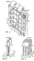
- Fig. 1 is a front perspective view,.partially in section, of the integrated circuit module system using the present invention.
- Fig. 2 is a perspective view of a single module containing one form of hollow heat sink of the present invention showing the air flow for cooling the module.
- Fig. 3 is a schematic illustration of one type of the impingement cooling of one type of hollow heat sink according to the present invention.
- Fig. 4 schematically illustrates the impingement air flow cooling of a straight fin heat sink structure of the present invention.
- Fig. 5A and 5B schematically illustrate other hollow heat sink forms according to the present invention.
- Referring to Fig. 1, an air cooling system for high density integrated circuit modules is schematically illustrated. Large scale integrated circuit chips (not shown) are packaged in
modules 10. The modules are in turn supported byprinted circuit board 11. Themodules 10 each have a heat conductive covering surface and attached to this covering surface is a plurality ofheat sink members 12. An air plenum 15 is spaced a suitable distance from the top surface of the integrated circuit module. Associated with the air plenum chamber 15 is anair moving device 16. Internal to the air plenum 15 in thewall 17 facing the integrated circuit board assembly of modules are a plurality ofopenings 18. Underneath eachopening 18 is preferably amodule 10 havingheat sink members 12 thereon. In the base of the assembly between the air plenum 15 and thecircuit board 11 isslit 19 which permits the exhausted air to be exited from the air cooling system. - Fig. 2 is a perspective schematic view of one module in the air cooling system which is illustrative of the theory of operation of the cooling of the integrated circuit module assembly of the present invention. All
heat sink members 12 are hollow in this embodiment. They are attached to the heat conductive coveringsurface 20 ofmodule 10. Attachment is typically by brazing, soldering or other conventional techniques. An opening oropenings 22 in the hollow heat sink extend from the surface of the coveringbody 20 toward the top opening of the hollow heat sink. - Fig. 3 is an enlargement of one of the hollow
heat sink members 12 of Fig. 2. The cooling air is directed by theair moving device 16 into the plenum 15. Theopenings 18 in thewall 17 cause a direct jet air impingement under the pressure of the air in the plenum to be directed onto thehollow heat sinks 12 of the integratedcircuit module 10. The air passing through the opening 18 impinges on the hollow heat sinks 12 with portions of the air entering the heat sinks and between the heat sinks. The air which enters the heat sinks will pass through and exit at the opening 22 at the bottom of theheat sink 12. The flow of air at the bottom creates a flow counter to that of the air boundary layer near the surface of thecovering surface 20 to thereby break up this air boundary layer. The break up of the air boundary layer due to this turbulence reduces the heat resistance between the module and the cooling medium. - Fig. 4 illustrates a second embodiment of the present invention wherein a straight
fin heat sink 30 is utilized. In this embodiment the heat conductive coveringsurface 20 of the module has attached thereto a straightfinned heat sink 30 which is composed of a heat conductive material. The straightfinned heat sink 30 contains slits oropenings 32 along its length. Air impingement flow is directed fromopenings 18 as described in the above hollow tube embodiment of the present invention. The air flow is impinging downward between the straightfinned heat sinks 30 and through the slits oropenings 32 to cause the turbulence necessary to reduce the air boundary layer to its lowest possible heat resistance characteristics. - There are other possible configurations for the hollow heat sinks of the present invention. Some of these are shown in Figs. 5A and 5B. The top 40 of the hollow seat sinks may be flared as shown in Fig. 5A to equal the heat sink spacing to direct more air into the pins. This structure also adds rigidity to the overall heat sink device. For parallel, rather than impingement air flow,
flow scoops 42 may be placed on the tops of the hollow heat sinks as shown in Fig. 5B to direct air into the top openings of the heat sinks. Thescoop 42 being larger than the heat sink opening will force additional air through the heat sink, accelerating it so that it exits at the bottom at a higher velocity then when entering the top (Venturi effect). This effect can be augmented further by employing inverted and truncated hollow cones with slots on the sidewalls. Aforementioned and other shapes with slots may be further enhanced by fluting the inside walls thus giving rise to air mixing and increased local velocities. It should be realized that conventional augmentations such as fluting, etc. will appreciably improve heat transfer rates only with the presence of slots on sidewalls through increased wash-effect. - It is preferred to have a plurality of slits equidistant along the surface of the heat sink as opposed to a single opening. The slits in both the Fig. 3 and Fig. 4 embodiments are preferred to extend more than one-half way from the covering body toward the top. The total opening area of the openings is between about one-third to one-half of the heat sink area. This ratio is further optimized for a given application as a function of the heat conduction required through the solid parts of the total heat sink. The amount of opening is important in making the inside surfaces of hollow tubes efficient in transferring heat. Similarly in flat fins, the openings provide more efficient heat transfer through the wash-effect.
- The following examples are included merely to aid in the understanding of the invention and variations may be made by one skilled in the art without departing from the spirit and scope of the invention.

- Each heat sink of the type described in each of the Examples in Table I was instrumented with more than 30 thermocouples both on the heat sink member side and on the side of the plate to which the members were attached. The heat sink was clamped to a wire heater and the assembly was placed in an air column. Air inlet temperature and temperatures at various points on the heat sink were measured. The power inputted to the heat sink was very carefully measured to account for extraneous heat losses. The thermal resistance of each heat sink was then calculated from the measured temperature and power dissipated by the heat sink. The slotted heat sinks of Example 2, 3 and 5 substantially reduced the thermal resistance and improved the performance of the heat sinks. It should be noted that staggered slots are preferred over in line slots especially in the case of flat fins.
Claims (8)
Applications Claiming Priority (2)
| Application Number | Priority Date | Filing Date | Title |
|---|---|---|---|
| US06/096,942 US4296455A (en) | 1979-11-23 | 1979-11-23 | Slotted heat sinks for high powered air cooled modules |
| US96942 | 1998-06-12 |
Publications (3)
| Publication Number | Publication Date |
|---|---|
| EP0029501A2 EP0029501A2 (en) | 1981-06-03 |
| EP0029501A3 EP0029501A3 (en) | 1981-06-17 |
| EP0029501B1 true EP0029501B1 (en) | 1984-05-02 |
Family
ID=22259852
Family Applications (1)
| Application Number | Title | Priority Date | Filing Date |
|---|---|---|---|
| EP80106265A Expired EP0029501B1 (en) | 1979-11-23 | 1980-10-15 | Heat sink member and aircooling system for semiconductor modules |
Country Status (5)
| Country | Link |
|---|---|
| US (1) | US4296455A (en) |
| EP (1) | EP0029501B1 (en) |
| JP (1) | JPS5676554A (en) |
| CA (1) | CA1140681A (en) |
| DE (1) | DE3067705D1 (en) |
Families Citing this family (94)
| Publication number | Priority date | Publication date | Assignee | Title |
|---|---|---|---|---|
| US4291364A (en) * | 1979-12-26 | 1981-09-22 | International Business Machines Corporation | Air-cooled hybrid electronic package |
| IN158133B (en) * | 1981-06-09 | 1986-09-13 | Gen Electric | |
| US4494171A (en) * | 1982-08-24 | 1985-01-15 | Sundstrand Corporation | Impingement cooling apparatus for heat liberating device |
| US4449164A (en) * | 1982-09-27 | 1984-05-15 | Control Data Corporation | Electronic module cooling system using parallel air streams |
| JPS59202657A (en) * | 1983-04-29 | 1984-11-16 | インタ−ナショナル ビジネス マシ−ンズ コ−ポレ−ション | Integral structure heat sink |
| US4546405A (en) * | 1983-05-25 | 1985-10-08 | International Business Machines Corporation | Heat sink for electronic package |
| US4628992A (en) * | 1984-01-23 | 1986-12-16 | At&T Information Systems | Induced flow heat exchanger |
| JPS61139536U (en) * | 1985-02-20 | 1986-08-29 | ||
| JPS61190665U (en) * | 1985-05-22 | 1986-11-27 | ||
| JPS62274798A (en) * | 1986-05-19 | 1987-11-28 | インタ−ナショナル ビジネス マシ−ンズ コ−ポレ−ション | Heatsink structure |
| US4674004A (en) * | 1986-07-03 | 1987-06-16 | Burroughs Corporation | Parallel-flow air system for cooling electronic equipment |
| US4777560A (en) * | 1987-09-02 | 1988-10-11 | Microelectronics And Computer Technology Corporation | Gas heat exchanger |
| FR2609233A1 (en) * | 1986-12-30 | 1988-07-01 | Bull Sa | DEVICE FOR VENTILATION OF COMPONENTS ARRANGED ON A PLATE |
| US4768581A (en) * | 1987-04-06 | 1988-09-06 | International Business Machines Corporation | Cooling system for semiconductor modules |
| GB2204181B (en) * | 1987-04-27 | 1990-03-21 | Thermalloy Inc | Heat sink apparatus and method of manufacture |
| US5083422A (en) * | 1988-03-25 | 1992-01-28 | General Electric Company | Method of breach cooling |
| US4916906A (en) * | 1988-03-25 | 1990-04-17 | General Electric Company | Breach-cooled structure |
| US5212625A (en) * | 1988-12-01 | 1993-05-18 | Akzo Nv | Semiconductor module having projecting cooling fin groups |
| US4880055A (en) * | 1988-12-07 | 1989-11-14 | Sundstrand Corporation | Impingement plate type heat exchanger |
| US5191230A (en) * | 1989-01-30 | 1993-03-02 | Heung Lap Yan | Circuit module fan assembly |
| US5079438A (en) * | 1989-01-30 | 1992-01-07 | Heung Lap Yan | Circuit module fan assembly |
| US5000254A (en) * | 1989-06-20 | 1991-03-19 | Digital Equipment Corporation | Dynamic heat sink |
| US5020586A (en) * | 1989-09-08 | 1991-06-04 | Hewlett-Packard Company | Air-cooled heat exchanger for electronic circuit modules |
| US5063476A (en) * | 1989-12-05 | 1991-11-05 | Digital Equipment Corporation | Apparatus for controlled air-impingement module cooling |
| US5196989A (en) * | 1990-04-09 | 1993-03-23 | Trw Inc. | Rigid circuit board structure using impingement cooling |
| US5097385A (en) * | 1990-04-18 | 1992-03-17 | International Business Machines Corporation | Super-position cooling |
| US5304845A (en) * | 1991-04-09 | 1994-04-19 | Digital Equipment Corporation | Apparatus for an air impingement heat sink using secondary flow generators |
| US5749413A (en) * | 1991-09-23 | 1998-05-12 | Sundstrand Corporation | Heat exchanger for high power electrical component and package incorporating same |
| JP2715752B2 (en) * | 1991-10-31 | 1998-02-18 | 住友金属工業株式会社 | Heat sink fin and manufacturing method thereof |
| US5455382A (en) * | 1991-10-31 | 1995-10-03 | Sumitomo Metal Industries, Ltd. | IC package heat sink fin |
| EP0560478B1 (en) * | 1992-02-10 | 1998-10-14 | Nec Corporation | Cooling structure for electronic circuit package |
| US5410448A (en) * | 1992-03-02 | 1995-04-25 | Digital Equipment Corporation | Adaptive cooling system |
| DE69305667T2 (en) * | 1992-03-09 | 1997-05-28 | Sumitomo Metal Ind | Heat sink with good heat dissipating properties and manufacturing processes |
| US5428503A (en) * | 1992-03-24 | 1995-06-27 | Hitachi, Ltd. | Jet cooling apparatus for cooling electronic equipment and computer having the same mounted thereon |
| JP2660879B2 (en) * | 1992-05-25 | 1997-10-08 | マンネスマン・アクチエンゲゼルシャフト | Electric machine with semiconductor switch |
| GB2276763B (en) * | 1993-03-30 | 1997-05-07 | Thermalloy Inc | Method and apparatus for dissipating thermal energy |
| EP0633608B1 (en) * | 1993-07-08 | 2000-10-11 | Sumitomo Metal Industries, Ltd. | Process for producing a pin-finned heat sink |
| JP3236137B2 (en) * | 1993-07-30 | 2001-12-10 | 富士通株式会社 | Semiconductor element cooling device |
| US5478221A (en) * | 1994-01-31 | 1995-12-26 | Lzr Electronics, Inc. | Miniature fan for printed circuit board |
| IL108860A (en) * | 1994-03-04 | 1998-10-30 | Elisra Gan Ltd | Heat radiating element |
| JPH07321265A (en) * | 1994-05-27 | 1995-12-08 | Fujitsu Ltd | Cooling structure in integrated circuit element module |
| IN192538B (en) * | 1995-02-01 | 2004-05-01 | Intel Corp | |
| US5604665A (en) * | 1995-06-30 | 1997-02-18 | International Business Machines Corporation | Multiple parallel impingement flow cooling with tuning |
| US5957194A (en) * | 1996-06-27 | 1999-09-28 | Advanced Thermal Solutions, Inc. | Plate fin heat exchanger having fluid control means |
| TW313277U (en) * | 1996-07-19 | 1997-08-11 | Mitac Int Corp | Transmission interface bridge device |
| US5781411A (en) * | 1996-09-19 | 1998-07-14 | Gateway 2000, Inc. | Heat sink utilizing the chimney effect |
| DE19756250C2 (en) * | 1997-12-17 | 2000-11-02 | Siemens Ag | Self-commutated converter of a voltage-impressing converter with high-performance modules |
| TW398651U (en) * | 1997-12-31 | 2000-07-11 | Global Win Technology Co Ltd | Cooling structure of hard disc |
| US6026895A (en) | 1998-02-06 | 2000-02-22 | Fujitsu Limited | Flexible foil finned heatsink structure and method of making same |
| US6154368A (en) * | 1998-09-14 | 2000-11-28 | Lucent Technologies, Inc. | Device and method for dissipating thermal energy of electronic circuit components |
| US6301779B1 (en) | 1998-10-29 | 2001-10-16 | Advanced Thermal Solutions, Inc. | Method for fabricating a heat sink having nested extended surfaces |
| US6308771B1 (en) | 1998-10-29 | 2001-10-30 | Advanced Thermal Solutions, Inc. | High performance fan tail heat exchanger |
| US6359781B1 (en) | 2000-04-21 | 2002-03-19 | Dell Products L.P. | Apparatus for cooling heat generating devices |
| KR20020065256A (en) * | 2001-02-06 | 2002-08-13 | 익스팬전자 주식회사 | Heat sink having heat transfer pipe |
| JP2002368473A (en) * | 2001-06-12 | 2002-12-20 | Mitsubishi Electric Corp | Heat dissipating apparatus for heat generating electronic component, electronic apparatus and electronic device having heat dissipating structure |
| JP2002368469A (en) * | 2001-06-12 | 2002-12-20 | Mitsubishi Electric Corp | Electronic apparatus and electronic equipment therefor |
| US6817405B2 (en) * | 2002-06-03 | 2004-11-16 | International Business Machines Corporation | Apparatus having forced fluid cooling and pin-fin heat sink |
| US7000691B1 (en) * | 2002-07-11 | 2006-02-21 | Raytheon Company | Method and apparatus for cooling with coolant at a subambient pressure |
| US6881039B2 (en) * | 2002-09-23 | 2005-04-19 | Cooligy, Inc. | Micro-fabricated electrokinetic pump |
| JP2006522463A (en) | 2002-11-01 | 2006-09-28 | クーリギー インコーポレイテッド | Optimal spreader system, apparatus and method for micro heat exchange cooled by fluid |
| US20050211418A1 (en) * | 2002-11-01 | 2005-09-29 | Cooligy, Inc. | Method and apparatus for efficient vertical fluid delivery for cooling a heat producing device |
| US8464781B2 (en) | 2002-11-01 | 2013-06-18 | Cooligy Inc. | Cooling systems incorporating heat exchangers and thermoelectric layers |
| US7836597B2 (en) * | 2002-11-01 | 2010-11-23 | Cooligy Inc. | Method of fabricating high surface to volume ratio structures and their integration in microheat exchangers for liquid cooling system |
| US6765796B2 (en) * | 2002-11-21 | 2004-07-20 | Teradyne, Inc. | Circuit board cover with exhaust apertures for cooling electronic components |
| US7044196B2 (en) * | 2003-01-31 | 2006-05-16 | Cooligy,Inc | Decoupled spring-loaded mounting apparatus and method of manufacturing thereof |
| US20040233639A1 (en) * | 2003-01-31 | 2004-11-25 | Cooligy, Inc. | Removeable heat spreader support mechanism and method of manufacturing thereof |
| US7591302B1 (en) * | 2003-07-23 | 2009-09-22 | Cooligy Inc. | Pump and fan control concepts in a cooling system |
| JP2005079175A (en) * | 2003-08-28 | 2005-03-24 | Toshiba Corp | Heat dissipating device |
| US20050269691A1 (en) * | 2004-06-04 | 2005-12-08 | Cooligy, Inc. | Counter flow micro heat exchanger for optimal performance |
| US20050274139A1 (en) * | 2004-06-14 | 2005-12-15 | Wyatt William G | Sub-ambient refrigerating cycle |
| US7992625B1 (en) * | 2006-08-18 | 2011-08-09 | United States Thermoelectric Consortium | Fluid-operated heat transfer device |
| US20070119572A1 (en) * | 2005-11-30 | 2007-05-31 | Raytheon Company | System and Method for Boiling Heat Transfer Using Self-Induced Coolant Transport and Impingements |
| US20070119568A1 (en) * | 2005-11-30 | 2007-05-31 | Raytheon Company | System and method of enhanced boiling heat transfer using pin fins |
| US20070175621A1 (en) * | 2006-01-31 | 2007-08-02 | Cooligy, Inc. | Re-workable metallic TIM for efficient heat exchange |
| US7539020B2 (en) | 2006-02-16 | 2009-05-26 | Cooligy Inc. | Liquid cooling loops for server applications |
| US20070209782A1 (en) * | 2006-03-08 | 2007-09-13 | Raytheon Company | System and method for cooling a server-based data center with sub-ambient cooling |
| TW200810676A (en) | 2006-03-30 | 2008-02-16 | Cooligy Inc | Multi device cooling |
| US20070227709A1 (en) * | 2006-03-30 | 2007-10-04 | Girish Upadhya | Multi device cooling |
| US7908874B2 (en) | 2006-05-02 | 2011-03-22 | Raytheon Company | Method and apparatus for cooling electronics with a coolant at a subambient pressure |
| US20070256815A1 (en) * | 2006-05-04 | 2007-11-08 | Cooligy, Inc. | Scalable liquid cooling system with modular radiators |
| US8651172B2 (en) | 2007-03-22 | 2014-02-18 | Raytheon Company | System and method for separating components of a fluid coolant for cooling a structure |
| CN101368713B (en) * | 2007-08-17 | 2010-11-10 | 富准精密工业(深圳)有限公司 | Heat radiator |
| JP4901960B2 (en) * | 2007-08-20 | 2012-03-21 | 三菱電機株式会社 | Display device |
| US7751189B2 (en) * | 2007-09-07 | 2010-07-06 | Intel Corporation | Cooling arrangement to cool components on circuit board |
| US7921655B2 (en) * | 2007-09-21 | 2011-04-12 | Raytheon Company | Topping cycle for a sub-ambient cooling system |
| US7934386B2 (en) * | 2008-02-25 | 2011-05-03 | Raytheon Company | System and method for cooling a heat generating structure |
| US7907409B2 (en) * | 2008-03-25 | 2011-03-15 | Raytheon Company | Systems and methods for cooling a computing component in a computing rack |
| US8376031B2 (en) * | 2008-05-20 | 2013-02-19 | Honeywell International Inc. | Blowerless heat exchanger based on micro-jet entrainment |
| US8266802B2 (en) * | 2008-06-18 | 2012-09-18 | International Business Machines Corporation | Cooling apparatus and method of fabrication thereof with jet impingement structure integrally formed on thermally conductive pin fins |
| US9277679B2 (en) | 2010-11-29 | 2016-03-01 | Honeywell International Inc. | Heat sink fin including angular dimples |
| US9111918B2 (en) | 2010-11-29 | 2015-08-18 | Honeywell International Inc. | Fin fabrication process for entrainment heat sink |
| WO2015094125A1 (en) * | 2013-12-16 | 2015-06-25 | Sieva, Podjetje Za Razvoj In Trženje V Avtomobilski Industriji, D.O.O. | High performance heat exchanger with inclined pin fin aragnement means and a method of producing the same |
| KR101543229B1 (en) | 2014-10-24 | 2015-08-11 | 주식회사 이즈 | Heat sink for pipe |
| DE102018221951A1 (en) * | 2018-12-17 | 2020-06-18 | Rolls-Royce Deutschland Ltd & Co Kg | Tubular cooling fins and their application |
Family Cites Families (7)
| Publication number | Priority date | Publication date | Assignee | Title |
|---|---|---|---|---|
| USRE25184E (en) * | 1959-08-03 | 1962-06-12 | Mcadam | |
| US3193610A (en) * | 1962-08-10 | 1965-07-06 | Atlee Corp | Shields for vacuum tubes and the like |
| SE350874B (en) * | 1970-03-05 | 1972-11-06 | Asea Ab | |
| US3670215A (en) * | 1970-09-28 | 1972-06-13 | Staver Co Inc The | Heat dissipator for integrated circuit |
| FR2157094A5 (en) * | 1971-10-18 | 1973-06-01 | Thomson Csf | |
| US4202408A (en) * | 1978-03-06 | 1980-05-13 | Temple Robert S | Jet type heat exchanger |
| JPS6234450Y2 (en) * | 1978-06-07 | 1987-09-02 |
-
1979
- 1979-11-23 US US06/096,942 patent/US4296455A/en not_active Expired - Lifetime
-
1980
- 1980-09-12 JP JP12619180A patent/JPS5676554A/en active Granted
- 1980-09-16 CA CA000360338A patent/CA1140681A/en not_active Expired
- 1980-10-15 DE DE8080106265T patent/DE3067705D1/en not_active Expired
- 1980-10-15 EP EP80106265A patent/EP0029501B1/en not_active Expired
Also Published As
| Publication number | Publication date |
|---|---|
| EP0029501A3 (en) | 1981-06-17 |
| CA1140681A (en) | 1983-02-01 |
| EP0029501A2 (en) | 1981-06-03 |
| JPS5676554A (en) | 1981-06-24 |
| JPS5719864B2 (en) | 1982-04-24 |
| US4296455A (en) | 1981-10-20 |
| DE3067705D1 (en) | 1984-06-07 |
Similar Documents
| Publication | Publication Date | Title |
|---|---|---|
| EP0029501B1 (en) | Heat sink member and aircooling system for semiconductor modules | |
| US5304845A (en) | Apparatus for an air impingement heat sink using secondary flow generators | |
| US5083194A (en) | Air jet impingement on miniature pin-fin heat sinks for cooling electronic components | |
| US5592363A (en) | Electronic apparatus | |
| JP2708495B2 (en) | Semiconductor cooling device | |
| US5195576A (en) | Lsi cooling apparatus and computer cooling apparatus | |
| EP0552538B1 (en) | Narrow channel finned heat sinking for cooling high power electronic components | |
| US4277816A (en) | Electronic circuit module cooling | |
| Goldberg | Narrow channel forced air heat sink | |
| EP0551726B1 (en) | Circuit pack layout with improved dissipation of heat produced by high power electronic components | |
| US6817405B2 (en) | Apparatus having forced fluid cooling and pin-fin heat sink | |
| US5946190A (en) | Ducted high aspect ratio heatsink assembly | |
| US4449164A (en) | Electronic module cooling system using parallel air streams | |
| JP3236137B2 (en) | Semiconductor element cooling device | |
| US3790859A (en) | Electronic package header system having omni-directional heat dissipation characteristic | |
| JP5039916B2 (en) | Heat distribution assembly, system for heat transfer and method for heat control (high power microjet cooler) | |
| US5705854A (en) | Cooling apparatus for electronic device | |
| EP0274486A1 (en) | Parallel-flow air system for cooling electronic equipment. | |
| JPH09223883A (en) | Cooling equipment of electronic apparatus | |
| US5166775A (en) | Air manifold for cooling electronic devices | |
| US5810072A (en) | Forced air cooler system | |
| US6736192B2 (en) | CPU cooler | |
| JP3002611B2 (en) | Heating element cooling device | |
| JP3030526B2 (en) | Semiconductor cooling structure | |
| US5504651A (en) | Cooling apparatus for electronic equipment |
Legal Events
| Date | Code | Title | Description |
|---|---|---|---|
| PUAI | Public reference made under article 153(3) epc to a published international application that has entered the european phase |
Free format text: ORIGINAL CODE: 0009012 |
|
| PUAL | Search report despatched |
Free format text: ORIGINAL CODE: 0009013 |
|
| AK | Designated contracting states |
Designated state(s): DE FR GB IT |
|
| AK | Designated contracting states |
Designated state(s): DE FR GB IT |
|
| 17P | Request for examination filed |
Effective date: 19810623 |
|
| ITF | It: translation for a ep patent filed |
Owner name: IBM - DR. ARRABITO MICHELANGELO |
|
| GRAA | (expected) grant |
Free format text: ORIGINAL CODE: 0009210 |
|
| AK | Designated contracting states |
Designated state(s): DE FR GB IT |
|
| REF | Corresponds to: |
Ref document number: 3067705 Country of ref document: DE Date of ref document: 19840607 |
|
| ET | Fr: translation filed | ||
| PLBE | No opposition filed within time limit |
Free format text: ORIGINAL CODE: 0009261 |
|
| STAA | Information on the status of an ep patent application or granted ep patent |
Free format text: STATUS: NO OPPOSITION FILED WITHIN TIME LIMIT |
|
| 26N | No opposition filed | ||
| ITTA | It: last paid annual fee | ||
| PGFP | Annual fee paid to national office [announced via postgrant information from national office to epo] |
Ref country code: FR Payment date: 19940930 Year of fee payment: 15 |
|
| PGFP | Annual fee paid to national office [announced via postgrant information from national office to epo] |
Ref country code: DE Payment date: 19941026 Year of fee payment: 15 |
|
| PGFP | Annual fee paid to national office [announced via postgrant information from national office to epo] |
Ref country code: GB Payment date: 19950926 Year of fee payment: 16 |
|
| PG25 | Lapsed in a contracting state [announced via postgrant information from national office to epo] |
Ref country code: FR Effective date: 19960628 |
|
| PG25 | Lapsed in a contracting state [announced via postgrant information from national office to epo] |
Ref country code: DE Effective date: 19960702 |
|
| REG | Reference to a national code |
Ref country code: FR Ref legal event code: ST |
|
| PG25 | Lapsed in a contracting state [announced via postgrant information from national office to epo] |
Ref country code: GB Effective date: 19961015 |
|
| GBPC | Gb: european patent ceased through non-payment of renewal fee |
Effective date: 19961015 |