EP0029342A1 - Remote inspection equipment - Google Patents
Remote inspection equipment Download PDFInfo
- Publication number
- EP0029342A1 EP0029342A1 EP80304054A EP80304054A EP0029342A1 EP 0029342 A1 EP0029342 A1 EP 0029342A1 EP 80304054 A EP80304054 A EP 80304054A EP 80304054 A EP80304054 A EP 80304054A EP 0029342 A1 EP0029342 A1 EP 0029342A1
- Authority
- EP
- European Patent Office
- Prior art keywords
- camera
- carriage
- unit according
- unit
- motor
- Prior art date
- Legal status (The legal status is an assumption and is not a legal conclusion. Google has not performed a legal analysis and makes no representation as to the accuracy of the status listed.)
- Withdrawn
Links
Images


Classifications
-
- G—PHYSICS
- G01—MEASURING; TESTING
- G01M—TESTING STATIC OR DYNAMIC BALANCE OF MACHINES OR STRUCTURES; TESTING OF STRUCTURES OR APPARATUS, NOT OTHERWISE PROVIDED FOR
- G01M3/00—Investigating fluid-tightness of structures
- G01M3/005—Investigating fluid-tightness of structures using pigs or moles
-
- G—PHYSICS
- G01—MEASURING; TESTING
- G01M—TESTING STATIC OR DYNAMIC BALANCE OF MACHINES OR STRUCTURES; TESTING OF STRUCTURES OR APPARATUS, NOT OTHERWISE PROVIDED FOR
- G01M3/00—Investigating fluid-tightness of structures
- G01M3/38—Investigating fluid-tightness of structures by using light
Definitions
- lined pipes come in a number of sizes, most of which are standardised, but a number of which are custom built. It is envisaged that the carriage 11 will be provided with skids 12 for a number of standard sizes, e.g. for pipes of 9 inches (22.5 cm), 12 inches (30 cm), 15 inches (37.5 cm), 18 inches (45 cm) and 24 inches (60 cm) diameter pipes.
- the skids will be in sets of four, i.e. a pair of trailing skids and a pair of leading skids for each standard size, and the variation will be achieved by differences in the length of the struts 13 extended between the skids 12 and skid supporting brackets 14.
- the unit 32 is mounted on a main shaft 35 which is longitudinally adjustable with respect to a rotary shaft 36 which is mounted in bearings in or on the end plates 31 and 33.
- Rotation of the shaft 36 is obtained by means of a motor and gear box unit 37 having a drive pinion 38 meshing with a pinion 39 solid on the shaft 36.
- the motor 37 is reversible and is designed so that the shaft 36 can carry the unit 32 through an arc of about 260°. In order to see the extent of this arc, reference may be made to figure 5 which shows a second camera 41 mounted in fixed position on the unit, and its extreme positions are shown at 41a and 41b.
- the unit 32 is mounted in a slideway 50, and is provided with a rack 54 co-operable with a pinion 55 driven by a reversible motor and gear box unit 56 mounted for movement with the shaft 35 by means of a plate 57.
- the cable for the tiltable camera 49 is taken in via the centre of a hollow pivot shaft or trunnion.
- the exhaust air from the air motor 48 may be used to provide an air curtain to reduce splatter onto the camera 49.
Abstract
An inspection device for use in confined or inaccessible locations comprising a carriage having a body (11) mounted on skids (not shown) or other means for transport within the location. The body carries a unit (32) so as to be adjustable longitudinally by a motor (44), angularly by a motor (37), and radially by a motor (56). The unit carries a camera (49) movable between a position (49a) where it is trained along the lined pipe in a generally radial position. A second camera (41) is mounted in fixed position on the unit (32).
Description
- This invention relates to remote inspection equipment for use in pipe lines or other confined spaces for inspection of such spaces and possibly also for the monitoring of operations carried on in such spaces.
- Various proposals have been made for moving television cameras through pipes or conduits for purposes of inspection. For example, United Kingdom Patent Specification 1474593 shows a camera mounted on skids. This camera is not shown as having any adjustment in relation to the skids. United Kingdom patent specification 1345108 discloses the use of a camera or a carriage, the camera head being rotatable about the optical axis of a camera lens. This enables the wall of a pipe to be viewed directly and radially. In United Kingdom Patent specification 1097585 there is shown a lens assembly which is pivotable on the camera tube to enable a better view to be obtained when looking generally axially along a curved pipe.
- According to the invention, there is provided a remotely controllable television camera unit comprising a carriage adapted to be moved within a confined or inaccessible space and clamped in position therein, and a television camera pivotally mounted on the carriage for movement between an axially directed position and a generally radially directed position and provided with remotely controlled means for pivoting the camera, adjusting the position of the camera longitudinally of the carriage and for operating the camera.
- A typical use would be in the inspection of water mains and sewers which are too small for access e.g. in the range from about 9 inches (22.5 cm) up to 24 inches (60 cm). Many other uses will arise wherein it is required to inspect a space too small for human access by using a remotely controlled television camera. In particular, the equipment may also carry means for carrying out an operation in the space, e.g. cutting a lateral connection aperture in the lining of a newly lined pipe.
- The camera may for example be mounted on a sliding block to achieve radial adjustment, and the sliding block may be rotated, together with a co-operating slideway to achieve rotary adjustment.
- In order to provide for longitudinal adjustment on the carriage, the block and its slideway may be longitudinally adjustable on the carriage.
- Alternatively the camera may be mounted for angular adjustment on the carriage and the mounting may be longitudinally adjustable.
- The carriage may be provided with skids to assist in its transport and provided with a clamping pad to hold it in selected position.
- The arrangement will normally carry lighting for illuminating the area to be covered by the camera. Further, an additional camera may be provided to give an off-centre view longitudinally from the carriage.
- The invention will be further described with reference to the accompanying drawings, which show a preferred embodiment of the invention and in which :-
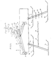
- Figure 1 is a side elevation of a carriage showing its support and clamping arrangement;
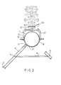
- Figure 2 is an end elevation of the carriage of Figure 1;
- Figure 3 is a partial view of the carriage of Figure 1;
- Figure 4 is a vertical sectional view of the carriage of Figure 1 with additional parts shown in elevation;
- Figure 5 is an end elevation of the structure of figure 4;
- Figure 6 is a partial plan view of the structure of Figure 4;
- Figure 7 is a view similar to Figure 4 showing some modifications; , and
- Figure 8 is a perspective view showing the modified assembly.
- Attention is drawn to co-pending application No.$ filed simultaneously herewith and entitled "Lining Cutter and Cutting Method", and claiming priority from United Kingdom application No. 7940162.
- In that application there is described and claimed a lining cutter including a remotely controlled television camera, and the description that follows is similar to that in the said co-pending application. However, the inspection of the confined interiors of pipes and other confined spaces by remotely controlled television cameras, and also the monitoring of activities other than cutting renders the equipment useful with or without the provision of a cutter.
- Turning now to figures 1 to 3, the body of a carriage is shown in outline at 11, and these figures are designed to show the supports on which the
carriage 11 may be drawn through a lined pipe, or other confined space, and then clamped in position. - It will be understood that lined pipes come in a number of sizes, most of which are standardised, but a number of which are custom built. It is envisaged that the
carriage 11 will be provided withskids 12 for a number of standard sizes, e.g. for pipes of 9 inches (22.5 cm), 12 inches (30 cm), 15 inches (37.5 cm), 18 inches (45 cm) and 24 inches (60 cm) diameter pipes. The skids will be in sets of four, i.e. a pair of trailing skids and a pair of leading skids for each standard size, and the variation will be achieved by differences in the length of thestruts 13 extended between theskids 12 and skid supportingbrackets 14. Thestruts 13 will be secured to thebrackets 14 by means of pins and circlips so as to be reasonably readily removable and replaceable. Figure 1 shows askid 12 of a small size and a skid 12a of a larger size, and indicates the positions at 12b, 12c, and 12d of skids of the intermediate sizes. In view of the length of thestruts 13 for the skids of the larger and intermediate sizes, longitudinal andlateral tie rods large size 12a. It will be seen from Figure 2 in particular that thebody 11 is provided with a reinforcingband 17 in the zone of attachment of each of thebrackets 14. - When the body 1 is mounted on skids of the appropriate size, it will be substantially centrally located within the standard size pipe, and when working in a non-standard pipe, the body will be as nearly centralised as is possible by choice of the appropriate set of skids.
- In order to stabilise the position of the
body 11 in a pipe, it is provided with aclamping pad 21 pivotally mounted on a pair of jackingarms 22 themselves pivoted at 23 to thebody 11. Eachjacking arm 22 is associated with apneumatic ram 24 pivoted both on thebody 11 and on thejacking arm 22 so as to push theresilient face 21a of the clamping pad against the pipe lining. Theram 24 is preferably single acting so that in the event of failure of the air supply, the carriage is released from the lining and can be removed. Various positions of thepad 21 are illustrated particularly in Figure 2. - For some of the larger sizes of pipe, the
jacking arms 22 may be extended byextension arms 22a to increase their length sufficiently for adequate movement of thepad 21 with a fairly limited stroke of therams 24. It will be seen that the body is also provided withreinforcements rams 24 and jackingarms 22 are connected. For clarity of illustration, therams 24 have been omitted from Figure 2. - Turning now to Figure 4, this shows details of the internal components of the
body 11, and also shows a cutter and camera unit which is indirectly mounted on the body so as to be carried thereby through the pipe and adjusted and operated within the pipe under remote control, with monitoring by the camera. The interior of thebody 11 is maintained under a slight superatmospheric pressure so as to prevent inward leakage of dust and other foreign matter. Fixedly mounted with thebody 11 by means ofscrews 31a is arear end plate 31, and at the opposite end adjacent the camera unit indicated generally by 32 is afront end plate 33, also fixed. Also fixedly mounted within the body is achassis plate 34. Theunit 32 is mounted on amain shaft 35 which is longitudinally adjustable with respect to arotary shaft 36 which is mounted in bearings in or on theend plates shaft 36 is obtained by means of a motor andgear box unit 37 having adrive pinion 38 meshing with apinion 39 solid on theshaft 36. Themotor 37 is reversible and is designed so that theshaft 36 can carry theunit 32 through an arc of about 260°. In order to see the extent of this arc, reference may be made to figure 5 which shows asecond camera 41 mounted in fixed position on the unit, and its extreme positions are shown at 41a and 41b. - In order that the axial position of the
unit 32 may be varied in relation to thebody 11, themain shaft 35 is slidable within the rotatingshaft 36 and is prevented from rotation relative thereto by means of a slidingstud 42 engaged in aguide slot 43 in the rotatingshaft 36. In order to achieve controlled longitudinal movement of theshaft 35, areversible motor 44 is mounted on therear end plate 31 and drives alead screw 45 co-operable with acaptive nut device 46 solid with theshaft 35. By this means, a fine and continuous adjustment of the position of theunit 32 axially relative to thebody 11 can be achieved. - The
unit 32 itself carries thecamera 41 already referred to mounted oncantilever brackets 47, and in addition it carries apneumatic cutter motor 48 with anoutput 48a adapted to mount a suitable cutter which is chosen to meet the duty in hand. The motor casing is also fixedly mounted on theunit 32. Also mounted on the unit is asecond television camera 49 which is pivotable from the generally radial position shown in Figures 4 and 6, in which it is trained on the aperture end of the cutter to a forwardly pointing position illustrated in phantom in Figure 4 and in full lines in Figure 5 indicated by thereference 49a. Limit stops may be provided to stabilize the camera in these two end positions, and the drive between them is obtained from areversible motor 51 having anoutput bevel gear 52 co-operating with abevel gear 53 connected to the mounting for thecamera 49. Thecamera 49 may be stopped at any required intermediate position. - In order to provide radial adjustment of the cutter, and
cameras unit 32 is mounted in aslideway 50, and is provided with arack 54 co-operable with apinion 55 driven by a reversible motor andgear box unit 56 mounted for movement with theshaft 35 by means of aplate 57. - It is envisaged that the
motors unit 32 will also carry lights for illuminating the area being worked on by the cutter driven by themotor 48, and also directed along the pipes in the direction of movement of the carriage, namely to the right as illustrated so as to illuminate the area covered by thecamera 41 and thecamera 49 when in the forwardly pointing position. - The air supply for the
ram 24 and thecutter motor 48 will be controlled by solenoid valves mounted in or on thebody 11. - When a pipe is provided with a lining in the manner hereinbefore described, the lining is cured under a certain amount of pressure, and therefore bulges somewhat into the lateral connections to the original pipe line, and these bulges can be viewed by means of the
cameras rams 24 to push theclamping plate 21 against the lining to stabilize thebody 11. Thecamera 49 is then swung into the position where it is trained on the working end of the cutter and the longitudinal and rotary positions of theunit 32 are adjusted until the cutter is lined up on the point to be cut. Themotor 56 is then started to advance the cutter and themotor 48 is also started when appropriate to commence cutting: If longitudinal, angular or radial adjustment of the cutter is required during cutting, this can be continuously carried out by appropriate operation of themotors unit 32 is returned to the rest position, the carriage is released by retraction of therams 24, thecamera 49 returns to its forward pointing position and the winching recommenced. - If required, splash guards can be provided to minimise the amount of splashing onto the lens of the
camera 49 in particular. The space within thebody 11 and below theshaft 36 in the position illustrated in Figure 4 may be utilised for spare pipeline and cable to enable controls to be taken to themotor 56 as it moves longitudinally relative to thebody 11, and the area below thechassis plate 34 is preferably also used to house printed circuit boards for the controls and also for the television cameras. By mounting the bulk of the electronic components of thecameras unit 32 can be reduced, and the advantages of this will be clear. Also some preset controls for the cameras, which may need to be periodically adjusted are mounted for access from outside thebody 11, so that the unit need not be dismantled for the adjustment to be made. - Turning now to figures 7 and 8, various modifications are shown. In particular figure 7 shows the
lead screw 45 as being slidably mounted in aguide tube 61 by means of anenlarged head 62. This gives support for thescrew 45 while enabling reasonable simple dismantling for maintenance. Theguide tube 61 acts as a mount for thecaptive nut 46 and has atongue 63 solidly attached toend plate 64 on themain shaft 35. Also, as shown in both figures 7 and 8, the camera andcutter unit 32 is arranged so that only thecutter 48 and its motor are mounted on aslide 66 co-operating with aslideway 67 solid with theend plate 64 as themain shaft 35. Thecamera 49 and its tilt motor andgear box unit 56 are mounted onbrackets 68 solid with theslideway 67 and thecantilever arms 47 for thecamera 41 are also mounted on thebrackets 68. Also shown arelights 69 on thecamera 41 and a pair oflights 71 on thecamera 49, which is shown in an intermediate position in figure 8 for clarity of illustration. - The cable for the
tiltable camera 49 is taken in via the centre of a hollow pivot shaft or trunnion. - The exhaust air from the
air motor 48 may be used to provide an air curtain to reduce splatter onto thecamera 49. - Although the present invention has been particularly described in conjunction with a cutter it will be appreciated that the remotely adjustable television camera arrangement finds many uses independently of the cutter in the inspection of pipelines and other confined or inaccessible spaces and in monitoring processes other than cutting.
Claims (8)
1. A remotely controllable television camera unit comprising a carriage adapted to be moved within a confined or inaccessible space and a television camera mounted on the carriage, characterised in that the television camera is pivotally mounted on the carriage for movement between an axially directed position and a radially directed position, the carriage is provided with means for clamping it in position in the space and is provided with remotely controlled means for pivoting the camera, adjusting the position of the camera longitudinally of the carriage and for operating the camera. ,
2. A unit according to claim 1, characterised in that the camera is mounted on a sliding block to achieve radial adjustment.
3. A unit according to claim 2, characterised in that the block is driven relative to a co-operating slideway by a rack and pinion drive.
4. A unit according to claim 3, characterised in that the block and slideway are rotatable on the carriage to achieve an angular adjustment of the camera.
5. A unit according to claim 3 or 4, characterised in that the block and slideway are longitudinally adjustable on the carriage.
6. A unit according to claim 1, in which the camera is mounted on a support for angular and axial adjustment on the carriage.
7. A camera unit according to any of the preceding claims, characterised by including lighting means for illuminating the area to be covered by the camera.
8. A camera unit according to any of the preceding claims, characterised by comprising a further camera directed to give an off-centre view longitudinally from the carriage.
Applications Claiming Priority (2)
| Application Number | Priority Date | Filing Date | Title |
|---|---|---|---|
| GB7940161 | 1979-11-20 | ||
| GB7940161 | 1979-11-20 |
Publications (1)
| Publication Number | Publication Date |
|---|---|
| EP0029342A1 true EP0029342A1 (en) | 1981-05-27 |
Family
ID=10509321
Family Applications (1)
| Application Number | Title | Priority Date | Filing Date |
|---|---|---|---|
| EP80304054A Withdrawn EP0029342A1 (en) | 1979-11-20 | 1980-11-12 | Remote inspection equipment |
Country Status (2)
| Country | Link |
|---|---|
| EP (1) | EP0029342A1 (en) |
| GB (1) | GB2064059B (en) |
Cited By (4)
| Publication number | Priority date | Publication date | Assignee | Title |
|---|---|---|---|---|
| EP0064342A2 (en) * | 1981-04-29 | 1982-11-10 | Edmund Nuttall Limited | Remote inspection equipment |
| GB2147080A (en) * | 1983-08-19 | 1985-05-01 | Europa Engineering | Apparatus for and method of repairing ducts |
| GB2169984A (en) * | 1985-01-17 | 1986-07-23 | Gen Electric | Ultrasonic transducer assembly |
| FR2599151A1 (en) * | 1986-05-20 | 1987-11-27 | British Nuclear Fuels Plc | PIPING INSPECTION APPARATUS |
Families Citing this family (9)
| Publication number | Priority date | Publication date | Assignee | Title |
|---|---|---|---|---|
| JPS5826256A (en) * | 1981-08-07 | 1983-02-16 | Kubota Ltd | Inspecting device for pipe |
| DE3138484A1 (en) * | 1981-09-28 | 1983-04-14 | Deutsche Gesellschaft für Wiederaufarbeitung von Kernbrennstoffen mbH, 3000 Hannover | "METHOD FOR MAINTENANCE OF DEVICES AND COMPONENTS IN HOT CELLS, ESPECIALLY REPROCESSING PLANTS FOR WASTE NUCLEAR FUELS, AND DEVICE FOR CARRYING OUT THE METHOD |
| GB2124728B (en) * | 1982-07-01 | 1985-11-13 | Micro Consultants Ltd | Cable television transmission |
| GB2129653A (en) * | 1982-11-02 | 1984-05-16 | Ian Roland Yarnell | Remotely controllable mounting for camera or tool |
| GB2192442A (en) * | 1986-07-11 | 1988-01-13 | Tracey Stephen | Lining a duct |
| CH675620A5 (en) * | 1987-03-31 | 1990-10-15 | Sika Robotics Ag | |
| GB2248004A (en) * | 1990-08-11 | 1992-03-18 | Atomic Energy Authority Uk | Device for inspecting internal screw threads |
| GB2253115A (en) * | 1991-01-09 | 1992-08-26 | Underwater Tools Limited | Remotely controlled television camera inspection system |
| GB2342419B (en) * | 1998-10-05 | 2002-09-18 | Pearpoint Ltd | Pipe inspection device |
Citations (4)
| Publication number | Priority date | Publication date | Assignee | Title |
|---|---|---|---|---|
| US2849530A (en) * | 1955-09-12 | 1958-08-26 | John H Fleet | Means for observing boreholes |
| US3715484A (en) * | 1971-02-11 | 1973-02-06 | Conco Inc | Duct scanning apparatus |
| US3761623A (en) * | 1971-03-03 | 1973-09-25 | Nippon Kokan Kk | Apparatus for examining the inner surface of pipes |
| US3885091A (en) * | 1973-10-24 | 1975-05-20 | Halliburton Co | Method and apparatus for pipeline inspection |
-
1980
- 1980-11-12 EP EP80304054A patent/EP0029342A1/en not_active Withdrawn
- 1980-11-12 GB GB8036359A patent/GB2064059B/en not_active Expired
Patent Citations (4)
| Publication number | Priority date | Publication date | Assignee | Title |
|---|---|---|---|---|
| US2849530A (en) * | 1955-09-12 | 1958-08-26 | John H Fleet | Means for observing boreholes |
| US3715484A (en) * | 1971-02-11 | 1973-02-06 | Conco Inc | Duct scanning apparatus |
| US3761623A (en) * | 1971-03-03 | 1973-09-25 | Nippon Kokan Kk | Apparatus for examining the inner surface of pipes |
| US3885091A (en) * | 1973-10-24 | 1975-05-20 | Halliburton Co | Method and apparatus for pipeline inspection |
Cited By (5)
| Publication number | Priority date | Publication date | Assignee | Title |
|---|---|---|---|---|
| EP0064342A2 (en) * | 1981-04-29 | 1982-11-10 | Edmund Nuttall Limited | Remote inspection equipment |
| EP0064342A3 (en) * | 1981-04-29 | 1982-12-29 | Edmund Nuttall Limited | Remote inspection equipment |
| GB2147080A (en) * | 1983-08-19 | 1985-05-01 | Europa Engineering | Apparatus for and method of repairing ducts |
| GB2169984A (en) * | 1985-01-17 | 1986-07-23 | Gen Electric | Ultrasonic transducer assembly |
| FR2599151A1 (en) * | 1986-05-20 | 1987-11-27 | British Nuclear Fuels Plc | PIPING INSPECTION APPARATUS |
Also Published As
| Publication number | Publication date |
|---|---|
| GB2064059B (en) | 1984-05-23 |
| GB2064059A (en) | 1981-06-10 |
Similar Documents
| Publication | Publication Date | Title |
|---|---|---|
| EP0029343A2 (en) | Lining cutter and cutting method | |
| EP0029342A1 (en) | Remote inspection equipment | |
| CA1326145C (en) | Portable line boring machine | |
| KR20100094824A (en) | A robot for inspecting and repairing a pipe | |
| KR100808916B1 (en) | Device for welding inside-jointing portion of large caliber steel pipes | |
| US6508975B1 (en) | Automated internal pipe cutting device | |
| EP0084427A1 (en) | Cutting method and equipment | |
| JP3692462B2 (en) | Universal portable boring machine for automatically or semi-automatically performing boring and welding material distribution operations in internal and external blind and through holes | |
| JPH11510102A (en) | Universal portable boring machine for automatically or semi-automatically performing boring and welding material dispensing operations on blind holes and through holes | |
| JP3688981B2 (en) | Pipe inner wall processing equipment | |
| RU2300046C1 (en) | Autonomously energized vehicle for moving inside pipeline | |
| HU203697B (en) | Device for carrying out cutting and similar technological operations | |
| CN209812337U (en) | Novel pipeline robot based on electromagnetic technology and silica gel antiskid technology | |
| SU854610A1 (en) | Apparatus for working tube from inner side | |
| EP0064342A2 (en) | Remote inspection equipment | |
| JP2019187239A (en) | Mower implement | |
| DE102004021880B3 (en) | Mobile cutting machine for large-diameter pipe has housing with wheels connected to reduction gear to take machine into pipe | |
| CN216227797U (en) | Automatic welding equipment for metal hose | |
| CN219925088U (en) | Novel welding auxiliary fixtures | |
| CN220532853U (en) | Cable cutting device | |
| JP4352382B2 (en) | Tunnel wall cutting equipment | |
| CN213224032U (en) | Numerical control pipe bending machine for exhaust pipe production | |
| CN112475453B (en) | Cutter for cutting seamless steel pipe and using method thereof | |
| KR100344869B1 (en) | Pipe maintenance robot equiped with two tools | |
| JPS5862218A (en) | Method and apparatus for cutting steel tubular sheet pile |
Legal Events
| Date | Code | Title | Description |
|---|---|---|---|
| PUAI | Public reference made under article 153(3) epc to a published international application that has entered the european phase |
Free format text: ORIGINAL CODE: 0009012 |
|
| AK | Designated contracting states |
Designated state(s): AT BE CH DE FR IT LU NL SE |
|
| 17P | Request for examination filed |
Effective date: 19811029 |
|
| STAA | Information on the status of an ep patent application or granted ep patent |
Free format text: STATUS: THE APPLICATION IS DEEMED TO BE WITHDRAWN |
|
| 18D | Application deemed to be withdrawn |
Effective date: 19830715 |
|
| RIN1 | Information on inventor provided before grant (corrected) |
Inventor name: NAYLOR, PETER |