EP0026751A1 - Tool holder - Google Patents
Tool holder Download PDFInfo
- Publication number
- EP0026751A1 EP0026751A1 EP80850120A EP80850120A EP0026751A1 EP 0026751 A1 EP0026751 A1 EP 0026751A1 EP 80850120 A EP80850120 A EP 80850120A EP 80850120 A EP80850120 A EP 80850120A EP 0026751 A1 EP0026751 A1 EP 0026751A1
- Authority
- EP
- European Patent Office
- Prior art keywords
- tool holder
- series
- balls
- tool
- clamping
- Prior art date
- Legal status (The legal status is an assumption and is not a legal conclusion. Google has not performed a legal analysis and makes no representation as to the accuracy of the status listed.)
- Granted
Links
Images

Classifications
-
- B—PERFORMING OPERATIONS; TRANSPORTING
- B23—MACHINE TOOLS; METAL-WORKING NOT OTHERWISE PROVIDED FOR
- B23B—TURNING; BORING
- B23B31/00—Chucks; Expansion mandrels; Adaptations thereof for remote control
- B23B31/02—Chucks
- B23B31/10—Chucks characterised by the retaining or gripping devices or their immediate operating means
- B23B31/107—Retention by laterally-acting detents, e.g. pins, screws, wedges; Retention by loose elements, e.g. balls
- B23B31/1075—Retention by screws
- B23B31/1077—Retention by screws acting on a floating pin
-
- B—PERFORMING OPERATIONS; TRANSPORTING
- B23—MACHINE TOOLS; METAL-WORKING NOT OTHERWISE PROVIDED FOR
- B23B—TURNING; BORING
- B23B31/00—Chucks; Expansion mandrels; Adaptations thereof for remote control
- B23B31/02—Chucks
- B23B31/10—Chucks characterised by the retaining or gripping devices or their immediate operating means
- B23B31/107—Retention by laterally-acting detents, e.g. pins, screws, wedges; Retention by loose elements, e.g. balls
- B23B31/1071—Retention by balls
-
- B—PERFORMING OPERATIONS; TRANSPORTING
- B23—MACHINE TOOLS; METAL-WORKING NOT OTHERWISE PROVIDED FOR
- B23B—TURNING; BORING
- B23B31/00—Chucks; Expansion mandrels; Adaptations thereof for remote control
- B23B31/02—Chucks
- B23B31/24—Chucks characterised by features relating primarily to remote control of the gripping means
- B23B31/26—Chucks characterised by features relating primarily to remote control of the gripping means using mechanical transmission through the working-spindle
- B23B31/261—Chucks characterised by features relating primarily to remote control of the gripping means using mechanical transmission through the working-spindle clamping the end of the toolholder shank
- B23B31/265—Chucks characterised by features relating primarily to remote control of the gripping means using mechanical transmission through the working-spindle clamping the end of the toolholder shank by means of collets
-
- B—PERFORMING OPERATIONS; TRANSPORTING
- B23—MACHINE TOOLS; METAL-WORKING NOT OTHERWISE PROVIDED FOR
- B23B—TURNING; BORING
- B23B2270/00—Details of turning, boring or drilling machines, processes or tools not otherwise provided for
- B23B2270/20—Internally located features, machining or gripping of internal surfaces
-
- Y—GENERAL TAGGING OF NEW TECHNOLOGICAL DEVELOPMENTS; GENERAL TAGGING OF CROSS-SECTIONAL TECHNOLOGIES SPANNING OVER SEVERAL SECTIONS OF THE IPC; TECHNICAL SUBJECTS COVERED BY FORMER USPC CROSS-REFERENCE ART COLLECTIONS [XRACs] AND DIGESTS
- Y10—TECHNICAL SUBJECTS COVERED BY FORMER USPC
- Y10S—TECHNICAL SUBJECTS COVERED BY FORMER USPC CROSS-REFERENCE ART COLLECTIONS [XRACs] AND DIGESTS
- Y10S279/00—Chucks or sockets
- Y10S279/904—Quick change socket
- Y10S279/905—Quick change socket with ball detent
-
- Y—GENERAL TAGGING OF NEW TECHNOLOGICAL DEVELOPMENTS; GENERAL TAGGING OF CROSS-SECTIONAL TECHNOLOGIES SPANNING OVER SEVERAL SECTIONS OF THE IPC; TECHNICAL SUBJECTS COVERED BY FORMER USPC CROSS-REFERENCE ART COLLECTIONS [XRACs] AND DIGESTS
- Y10—TECHNICAL SUBJECTS COVERED BY FORMER USPC
- Y10T—TECHNICAL SUBJECTS COVERED BY FORMER US CLASSIFICATION
- Y10T279/00—Chucks or sockets
- Y10T279/17—Socket type
- Y10T279/17666—Radially reciprocating jaws
- Y10T279/17692—Moving-cam actuator
- Y10T279/17743—Reciprocating cam sleeve
- Y10T279/17752—Ball or roller jaws
-
- Y—GENERAL TAGGING OF NEW TECHNOLOGICAL DEVELOPMENTS; GENERAL TAGGING OF CROSS-SECTIONAL TECHNOLOGIES SPANNING OVER SEVERAL SECTIONS OF THE IPC; TECHNICAL SUBJECTS COVERED BY FORMER USPC CROSS-REFERENCE ART COLLECTIONS [XRACs] AND DIGESTS
- Y10—TECHNICAL SUBJECTS COVERED BY FORMER USPC
- Y10T—TECHNICAL SUBJECTS COVERED BY FORMER US CLASSIFICATION
- Y10T409/00—Gear cutting, milling, or planing
- Y10T409/30—Milling
- Y10T409/30952—Milling with cutter holder
Definitions
- This invention relates to a mounting device for securing a tool holder to a drive spindle comprising an adapter which, in use, is attached to the drive spindle and carries the tool holder.
- Drive spindles of machine tools are in their outer end usually provided with a conical bore, which is intended to receive a tool holder having a corresponding taper.
- a cutting tool has to be exchanged, then as a rule also the tool holder must be exchanged. Due to its taper the tool holder then has to be moved a long axial distance. This is with regard to the weight of the tool holder a heavy operation, which requires a great deal of room.
- An object of the present invention is to provide a mounting device in which the replaceable member of the tool holder has a comparatively low weight while at the same time requiring a small axial movement during detachment thereof.
- Tool holders having standard cone are usually secured by means of clamping elements, which require drive spindles with a bore passing longitudinally therethrough.
- the tool holder can be fastened with screws to the front end of the drive spindle, which is a stable connection, but, however, also is a time consuming operation.
- Another and the essential, object of the invention is to provide a mounting device which besides that it requires a small working space due to a short axial movement of the tool holder during exchange thereof can be used in connection with drive spindles without any longitudinal central bore.
- a further object of the invention is to provide a coupling, which can be connected and disconnected comparatively rapidly.
- Fig. 1 shows a longitudinal section through a preferred embodiment of a device according to the invention.
- the section is taken on the line I-I in Fig. 2.
- Fig. 2 is a section taken on the line II-II in Fig. 1 showing the tool holder in a clamped position.
- Fig. 3 is a section similar to that in Fig. 2 but showing the tool holder in a loosened position.
- Fig. 4 shows on an enlarged scale a portion of the ball looking system in Fig. 1.
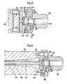
- Figs. 5 and 6 show a longitudinal section through alternative embodiments of a device according to the invention.
- front end and forwardly directed in the description and the claims relate to respectively the end of a member facing the cutting tool and a direction toward the cutting tool.
- a drive spindle 10 of a machine tool is in conventional manner provided with a conical bore 11.
- the bore 11 is intended to receive a standard base taper, not shown.
- an adapter 12 is fastened with screws 13 to the drive spindle 10.
- the adapter 12 is provided with a central recess, which has two inner cylindrical guiding surfaces 14, 15, which are intended to slidably engage with a close fit corresponding guiding surfaceson a tool bolder 1.6.
- the guiding surface 15 has a somewhat larger diameter than the guiding surface 14.
- a cutting tool, not shown, is attached to the tool holder 16 as illustrated in German PS 1.552.556.
- the tool holder 16 is locked against rotation relative to the adapter 12 by means of a guide member 17.
- a head bolt 18 is screwed into the rear end of the tool holder 16.
- the bolt 18 is provided with a groove 19 passing therearound.
- a clamping meansin form of a first series of balls 20 is arranged to be moved radially inwards to abutment against an abutting surface 21 in the groove 19, thereby applying a rearwardly directed force on the tool holder 16 so that an annular abutting surface 22 thereon is forced against the adapter 12.
- the abutting surface 21 extends in the transversal direction of the tool holder 16.
- a second series of balls 23 Radially outwardly of the first series of balls 20 there is a second series of balls 23.
- the balls 23 are guided in radial direction by means of a guiding surface 24 on the adapter 12 and a flange 25 on a lock ring 26.
- the balls 20, 23 are retained axially between opposed surfaces on the adapter 12 and the lock ring 26.
- a clamping member in form of a screw 27 is radially movable between two consecutive balls 23.
- the above consecutive balls 23 are wedgingly moved apart, thereby applying forces on two adjacent balls 20 in the first series. Due to the fact that the balls 20 are foreibly guided between two consecutive balls 23 in the second series the balls 20 then are forced radially inwards against the abutting surface 21. The force flow caused by the screw 27, thus, passes alternately via balls in the first and second series.
- the balls 20, 23 in the two series are equally spaced along the periphery of the bolt 18. In the preferred embodiment there is four balls 20 in the first series and tne calls are diametrically opposed in pairs. Three balls 23 15 the second series are positioned between two consecutive balls 20 with the exception that the screw 27 replaces one ball 23.
- a drive spindle 30 which does not have any conical bore but where a tool holder is intended to be fastened with screws.
- an adapter 31 is attached to the drive spindle 30 by means of screws 32.
- a cutting tool is connected to the adapter 31 by inserting a shaft end on the cutting tool into a bore 44 and in conventional manner fixing the shaft end therein.
- the adapter 31 is provided with a central recess, which has guiding surfaces 33, 34.
- a head bolt 36 is screwed into the rear end of a tool holder 35.
- the bolt 36 is provided with a groove passing therearound, which has an abutting surface 37.
- Two clamping members 38, 39 are synchronously movable in the adapter 31 in radially opposite directions by means of a double-threaded screw 40.
- the clamping members 38, 39 are guided by means of guide members 41, 42, which are fastened with screws to the adapter 31.
- the clamping members 38, 39 are provided with a projecting portion 43, which is intended to cooperate with the abutting surface 37, thereby providing a locking means.
- F ig. 1 an equally distributed clamping force is obtained since the clamping members 38 s 39 will move radially as a unit in case of any eccentricity of the bolt 36.
- Fig. 6 an embodiment is shown which certainly requires a drive spindle 50 Laving a traversing bore 51 out in which a tool holder 52 can be rapidly attached and detached to an adapter 59, while simultaneously requiring a small working space due to the short axial movement of the tool holder during exchange thereof.
- the tool holder 52 coincides with the tool holder 35 in Fig. 5 with the exception that the bolt 53 is provided with an inner groove 54.
- radial projections 55 on tongues of a slitted tubular element 56 are moved into the groove 54 by means of a rod 57, whereupon a rearwardly directed force is applied on an abutting surface 58 formed by the rear wall of the groove 54.
- the rod 57 and the element 56 are of the same basic design as shown in German OS 2.741.810.
Abstract
Description
- This invention relates to a mounting device for securing a tool holder to a drive spindle comprising an adapter which, in use, is attached to the drive spindle and carries the tool holder.
- Drive spindles of machine tools are in their outer end usually provided with a conical bore, which is intended to receive a tool holder having a corresponding taper. When a cutting tool has to be exchanged, then as a rule also the tool holder must be exchanged. Due to its taper the tool holder then has to be moved a long axial distance. This is with regard to the weight of the tool holder a heavy operation, which requires a great deal of room.
- An object of the present invention is to provide a mounting device in which the replaceable member of the tool holder has a comparatively low weight while at the same time requiring a small axial movement during detachment thereof.
- Tool holders having standard cone are usually secured by means of clamping elements, which require drive spindles with a bore passing longitudinally therethrough. Alternatively the tool holder can be fastened with screws to the front end of the drive spindle, which is a stable connection, but, however, also is a time consuming operation.
- Another and the essential, object of the invention is to provide a mounting device which besides that it requires a small working space due to a short axial movement of the tool holder during exchange thereof can be used in connection with drive spindles without any longitudinal central bore.
- A further object of the invention is to provide a coupling, which can be connected and disconnected comparatively rapidly.
- The above and other objects of the invention have been attained by giving the invention the characterizing features stated in the appending claims.
- The invention is described in detail in the following description with reference to the accompanying drawings in which three embodiments are shown by way of example. It is to be understood that these embodiments are only illustrative of the invention and that various modifications thereof may be made within the scope of the claims.
- In the drawings, Fig. 1 shows a longitudinal section through a preferred embodiment of a device according to the invention. For purposes of more clearly illustrating the ball locking system included therein the section is taken on the line I-I in Fig. 2.
- Fig. 2 is a section taken on the line II-II in Fig. 1 showing the tool holder in a clamped position.
- Fig. 3 is a section similar to that in Fig. 2 but showing the tool holder in a loosened position.
- Fig. 4 shows on an enlarged scale a portion of the ball looking system in Fig. 1.
- Figs. 5 and 6 show a longitudinal section through alternative embodiments of a device according to the invention.
- The expressions "front end" and "forwardly directed" in the description and the claims relate to respectively the end of a member facing the cutting tool and a direction toward the cutting tool.
- In Fig. 1, the front end of a
drive spindle 10 of a machine tool, not shown, is in conventional manner provided with aconical bore 11. Thebore 11 is intended to receive a standard base taper, not shown. According to the invention anadapter 12 is fastened withscrews 13 to thedrive spindle 10. Theadapter 12 is provided with a central recess, which has two inner cylindrical guidingsurfaces 14, 15, which are intended to slidably engage with a close fit corresponding guiding surfaceson a tool bolder 1.6. The guidingsurface 15 has a somewhat larger diameter than the guiding surface 14. A cutting tool, not shown, is attached to thetool holder 16 as illustrated in German PS 1.552.556. - The
tool holder 16 is locked against rotation relative to theadapter 12 by means of a guide member 17. - A
head bolt 18 is screwed into the rear end of thetool holder 16. Thebolt 18 is provided with agroove 19 passing therearound. During clamping of the tool holder 16 a clamping meansin form of a first series ofballs 20 is arranged to be moved radially inwards to abutment against anabutting surface 21 in thegroove 19, thereby applying a rearwardly directed force on thetool holder 16 so that an annular abutting surface 22 thereon is forced against theadapter 12. Theabutting surface 21 extends in the transversal direction of thetool holder 16. - Radially outwardly of the first series of
balls 20 there is a second series ofballs 23. Theballs 23 are guided in radial direction by means of a guidingsurface 24 on theadapter 12 and aflange 25 on alock ring 26. Theballs adapter 12 and thelock ring 26. - A clamping member in form of a
screw 27 is radially movable between twoconsecutive balls 23. Upon a radially inwardly directed movement of thescrew 27, i.e. from the position shown in Fig. 3 to the position shown in Fig. 2, the aboveconsecutive balls 23 are wedgingly moved apart, thereby applying forces on twoadjacent balls 20 in the first series. Due to the fact that theballs 20 are foreibly guided between twoconsecutive balls 23 in the second series theballs 20 then are forced radially inwards against theabutting surface 21. The force flow caused by thescrew 27, thus, passes alternately via balls in the first and second series. - The
balls bolt 18. In the preferred embodiment there is fourballs 20 in the first series and tne calls are diametrically opposed in pairs. Threeballs 23 15 the second series are positioned between twoconsecutive balls 20 with the exception that thescrew 27 replaces oneball 23. - In the preferred embodiment there is obtained an equally distributed clamping force around the periphery of the tool holder. In order to achieve this force equalization it is not necessary that the
bolt 18 is exactly centralized in thetool holder 16, since theballs belt 18. Thus, the required centralizing of the tool holder is achieved solely by means of the close-fitting guidingsurfaces 14, 15. Consequently, thebolt 18 and theclamping balls - In Fig. 5 there is shown a
drive spindle 30 which does not have any conical bore but where a tool holder is intended to be fastened with screws. This is as previously mentioned a time consuming operation. According to the invention an adapter 31 is attached to thedrive spindle 30 by means ofscrews 32. A cutting tool is connected to the adapter 31 by inserting a shaft end on the cutting tool into abore 44 and in conventional manner fixing the shaft end therein. In similarity with the embodiment according to Fig. 1 the adapter 31 is provided with a central recess, which has guidingsurfaces head bolt 36 is screwed into the rear end of atool holder 35. Thebolt 36 is provided with a groove passing therearound, which has anabutting surface 37. Twoclamping members screw 40. Theclamping members guide members 41, 42, which are fastened with screws to the adapter 31. Theclamping members abutting surface 37, thereby providing a locking means. In similarity with the embodiment according to Fig. 1 an equally distributed clamping force is obtained since theclamping members 38s 39 will move radially as a unit in case of any eccentricity of thebolt 36. - In Fig. 6 an embodiment is shown which certainly requires a
drive spindle 50 Laving a traversingbore 51 out in which atool holder 52 can be rapidly attached and detached to anadapter 59, while simultaneously requiring a small working space due to the short axial movement of the tool holder during exchange thereof. Thetool holder 52 coincides with thetool holder 35 in Fig. 5 with the exception that thebolt 53 is provided with aninner groove 54. During clamping of thetool holder 52radial projections 55 on tongues of a slittedtubular element 56 are moved into thegroove 54 by means of arod 57, whereupon a rearwardly directed force is applied on anabutting surface 58 formed by the rear wall of thegroove 54. Therod 57 and theelement 56 are of the same basic design as shown in German OS 2.741.810.
Claims (9)
Applications Claiming Priority (2)
| Application Number | Priority Date | Filing Date | Title |
|---|---|---|---|
| SE7907796A SE427732B (en) | 1979-09-20 | 1979-09-20 | tool holder |
| SE7907796 | 1979-09-20 |
Publications (2)
| Publication Number | Publication Date |
|---|---|
| EP0026751A1 true EP0026751A1 (en) | 1981-04-08 |
| EP0026751B1 EP0026751B1 (en) | 1983-12-28 |
Family
ID=20338863
Family Applications (1)
| Application Number | Title | Priority Date | Filing Date |
|---|---|---|---|
| EP80850120A Expired EP0026751B1 (en) | 1979-09-20 | 1980-08-13 | Tool holder |
Country Status (5)
| Country | Link |
|---|---|
| US (1) | US4412767A (en) |
| EP (1) | EP0026751B1 (en) |
| JP (1) | JPS5645347A (en) |
| DE (1) | DE3066001D1 (en) |
| SE (1) | SE427732B (en) |
Cited By (22)
| Publication number | Priority date | Publication date | Assignee | Title |
|---|---|---|---|---|
| FR2570308A1 (en) * | 1984-09-14 | 1986-03-21 | Beck August Gmbh Co | AXIAL TIGHTENING CONNECTION DEVICE BETWEEN A TOOL HOLDER AND A TOOL |
| DE3536183A1 (en) * | 1985-03-01 | 1986-09-04 | Fried. Krupp Gmbh, 4300 Essen | Tool arrangement with interchangeable tool head |
| EP0204671A2 (en) * | 1985-05-08 | 1986-12-10 | Santrade Ltd. | Tool coupling device |
| US4747735A (en) * | 1987-01-27 | 1988-05-31 | Kennametal Inc. | Toolholder and method of releasably mounting |
| DE3709299A1 (en) * | 1987-03-20 | 1988-09-29 | Index Werke Kg Hahn & Tessky | Tool-changing device for a machine tool |
| US4784542A (en) * | 1985-03-01 | 1988-11-15 | Fried. Krupp Gesellschaft Mit Beschrankter Haftung | Tool-mounting assembly having an exchangeable tool head |
| US4818161A (en) * | 1985-10-15 | 1989-04-04 | Cook Harold D | Tool holder system and method of use |
| US4844671A (en) * | 1987-05-11 | 1989-07-04 | Gottlieb Guhring Kg | Coupling device |
| EP0386522A2 (en) * | 1989-03-01 | 1990-09-12 | GÖLTENBODT PRÄZISIONS-WERKZEUG-UND MASCHINENFABRIK GmbH & CO. | Device for tool changing and clamping |
| US4971491A (en) * | 1985-10-15 | 1990-11-20 | Cook Harold D | Tool holder system and method of use |
| US5311654A (en) * | 1992-09-25 | 1994-05-17 | Cook Harold D | Tool holder system and method of making |
| WO1995030504A1 (en) * | 1994-05-05 | 1995-11-16 | Balaxman Oy | Tool coupling with means for centering and clamping |
| US5975816A (en) * | 1997-07-09 | 1999-11-02 | Cook; Harold D. | Harmonic dampener for rotary tool holder |
| US5979912A (en) * | 1997-07-09 | 1999-11-09 | Cook; Harold D. | Heavy-metal shrink fit cutting tool mount |
| US6035512A (en) * | 1997-07-09 | 2000-03-14 | Cook; Harold D. | Machine tool extension and method of forming the same |
| US6109842A (en) * | 1999-08-03 | 2000-08-29 | Cook; Harold D. | Tool holder with harmonic dampening drive mechanism |
| US6161309A (en) * | 1999-04-28 | 2000-12-19 | Cook; Harold D. | Heat shrink tool holder cooler |
| US6234729B1 (en) | 1999-04-28 | 2001-05-22 | Harold D. Cook | Shrink fit shoulder interface |
| US6382888B2 (en) | 1997-07-09 | 2002-05-07 | Harold D Cook | Vibration dampened spindle and tool holder assembly |
| US6425716B1 (en) | 2000-04-13 | 2002-07-30 | Harold D. Cook | Heavy metal burr tool |
| WO2007147711A1 (en) * | 2006-06-19 | 2007-12-27 | Komet Group Holding Gmbh | Junction between two components of a rotating tool system |
| US7886560B2 (en) | 2008-02-19 | 2011-02-15 | Cook Harold D | Heat shrink tool holder cooling cart |
Families Citing this family (8)
| Publication number | Priority date | Publication date | Assignee | Title |
|---|---|---|---|---|
| US4500232A (en) * | 1982-03-17 | 1985-02-19 | Boremaster Precision Tool & Mfg. | Boring bar |
| DE8631442U1 (en) * | 1986-11-25 | 1988-03-24 | Komet Stahlhalter- Und Werkzeugfabrik Robert Breuning Gmbh, 7122 Besigheim, De | |
| DE3711808A1 (en) * | 1987-04-08 | 1988-10-20 | Walter Gmbh Montanwerke | MULTI-PIECE CLAMPING SYSTEM, IN PARTICULAR FOR ROTARY TOOLS |
| FR2623430B1 (en) * | 1987-11-23 | 1990-03-02 | Pfalzgraf Emile | CONICAL TAIL MOUNTING DEVICE, PARTICULARLY CONE 7/24, WITH CONE AND FACE APPLICATION FOR ATTACHMENTS, TOOL HOLDERS AND TOOLS |
| EP0340369B1 (en) * | 1988-05-06 | 1992-03-04 | Emile Pfalzgraf | Device for assembling toolholders and tools having conical and facial contact surfaces particularly for machining centers with automatic or manual tool changers |
| ES2314525T3 (en) * | 1999-10-19 | 2009-03-16 | Kabushiki Kaisha Miyanaga | CUTTER FOR USE WITH A QUICK CHANGE SCROLL. |
| CA2488743A1 (en) * | 2004-12-08 | 2006-06-08 | Leonid S. Veinberg | Multi ball self-adjusting self-centering tool holder (mbssth) and multi ball self-adjusting self-centering clamping system (mbsscs) |
| US8033766B2 (en) * | 2008-05-09 | 2011-10-11 | Kennametal Inc. | Tool holder with ball clamping mechanism |
Citations (10)
| Publication number | Priority date | Publication date | Assignee | Title |
|---|---|---|---|---|
| DE1552556C (en) * | ||||
| CH248270A (en) * | 1945-08-30 | 1947-04-30 | Ag Starrfraesmaschinen | Quick-release chuck with a body that can be clamped in the same. |
| US2684249A (en) * | 1950-11-30 | 1954-07-20 | Giddings & Lewis | Toolhead and taper shank adapter |
| US2970844A (en) * | 1959-02-12 | 1961-02-07 | Scully Jones & Co | Tool holder-axial locking type |
| DE1996345U (en) * | 1968-08-01 | 1968-11-07 | Schmid Maschb Kg | CLAMPING DEVICE FOR FASTENING TOOLS |
| US3593614A (en) * | 1968-05-24 | 1971-07-20 | Innocenti Societa General Per | Chuck device for releasably attaching a milling cutter to a machine tool spindle |
| DE2541123A1 (en) * | 1974-09-18 | 1976-04-08 | Benno Koch | Mounting for machine tool cutter - has three parts locking together with spigots and threaded connections |
| DE2823609A1 (en) * | 1977-06-13 | 1978-12-14 | Kennametal Inc | DEVICE FOR ATTACHING A BASIC DISC OR CYLINDER SHAPED CUTTER TO A DRIVE SPINDLE |
| DE7827203U1 (en) * | 1978-09-13 | 1978-12-21 | Schmid, Herbert, 7253 Renningen | Tool holder |
| DE2741810A1 (en) * | 1977-09-16 | 1979-03-22 | Schmid Kosta Kg | Machine tool tool-holder securing system - has inner ring groove for clamp component additional to normal threaded section for drawbar |
Family Cites Families (15)
| Publication number | Priority date | Publication date | Assignee | Title |
|---|---|---|---|---|
| US1548730A (en) * | 1921-01-26 | 1925-08-04 | George E Mirfield | Method and apparatus for milling threads |
| US2250631A (en) * | 1939-10-16 | 1941-07-29 | Leblond Mach Tool Co R K | Crankshaft chuck |
| GB618470A (en) * | 1945-08-27 | 1949-02-22 | Rigid Ltd | Improvements in or relating to chucks |
| US3311023A (en) * | 1964-11-12 | 1967-03-28 | Ingersoll Milling Machine Co | Cutter shank tightener |
| DE1552556B1 (en) * | 1965-11-03 | 1971-02-18 | Schmid Maschb Kg | Centering of tools or tool holders in or on the spindle of machine tools |
| US3622170A (en) * | 1968-05-20 | 1971-11-23 | Kearney & Trecker Corp | Tool-locking mechanism |
| US3596917A (en) * | 1969-02-17 | 1971-08-03 | Monarch Machine Tool Co | Tool adapter |
| US3599996A (en) * | 1969-06-25 | 1971-08-17 | Donald G Holt | Toolholder for a machine tool |
| US3622169A (en) * | 1969-09-09 | 1971-11-23 | Hoadaille Ind Inc | Quick-change tool holder |
| US3658351A (en) * | 1970-04-03 | 1972-04-25 | Erickson Tool Co | Instant change tool holder |
| US3658352A (en) * | 1970-07-29 | 1972-04-25 | Houdaille Industries Inc | Quick change tool holders for automatic tool changers |
| US4077736A (en) * | 1977-04-01 | 1978-03-07 | Kearney & Trecker Corporation | Drill speeder for machine tools |
| JPS53140894A (en) * | 1977-05-12 | 1978-12-08 | Nakanishi Shika Kikai Seisakus | Chuck open*close device for dental handpiece |
| US4350463A (en) * | 1977-06-13 | 1982-09-21 | Kennametal Inc. | Arrangement for mounting a cutter |
| FR2437910A1 (en) * | 1978-10-06 | 1980-04-30 | Lauricella Robert | Chuck for rotary milling cutter - uses relative rotation of oval ring on round body to give ball convergence on ramped faces split sleeve which displaces axially |
-
1979
- 1979-09-20 SE SE7907796A patent/SE427732B/en unknown
-
1980
- 1980-08-13 EP EP80850120A patent/EP0026751B1/en not_active Expired
- 1980-08-13 DE DE8080850120T patent/DE3066001D1/en not_active Expired
- 1980-08-27 US US06/181,749 patent/US4412767A/en not_active Expired - Lifetime
- 1980-09-19 JP JP13141980A patent/JPS5645347A/en active Pending
Patent Citations (10)
| Publication number | Priority date | Publication date | Assignee | Title |
|---|---|---|---|---|
| DE1552556C (en) * | ||||
| CH248270A (en) * | 1945-08-30 | 1947-04-30 | Ag Starrfraesmaschinen | Quick-release chuck with a body that can be clamped in the same. |
| US2684249A (en) * | 1950-11-30 | 1954-07-20 | Giddings & Lewis | Toolhead and taper shank adapter |
| US2970844A (en) * | 1959-02-12 | 1961-02-07 | Scully Jones & Co | Tool holder-axial locking type |
| US3593614A (en) * | 1968-05-24 | 1971-07-20 | Innocenti Societa General Per | Chuck device for releasably attaching a milling cutter to a machine tool spindle |
| DE1996345U (en) * | 1968-08-01 | 1968-11-07 | Schmid Maschb Kg | CLAMPING DEVICE FOR FASTENING TOOLS |
| DE2541123A1 (en) * | 1974-09-18 | 1976-04-08 | Benno Koch | Mounting for machine tool cutter - has three parts locking together with spigots and threaded connections |
| DE2823609A1 (en) * | 1977-06-13 | 1978-12-14 | Kennametal Inc | DEVICE FOR ATTACHING A BASIC DISC OR CYLINDER SHAPED CUTTER TO A DRIVE SPINDLE |
| DE2741810A1 (en) * | 1977-09-16 | 1979-03-22 | Schmid Kosta Kg | Machine tool tool-holder securing system - has inner ring groove for clamp component additional to normal threaded section for drawbar |
| DE7827203U1 (en) * | 1978-09-13 | 1978-12-21 | Schmid, Herbert, 7253 Renningen | Tool holder |
Cited By (28)
| Publication number | Priority date | Publication date | Assignee | Title |
|---|---|---|---|---|
| FR2570308A1 (en) * | 1984-09-14 | 1986-03-21 | Beck August Gmbh Co | AXIAL TIGHTENING CONNECTION DEVICE BETWEEN A TOOL HOLDER AND A TOOL |
| US4784542A (en) * | 1985-03-01 | 1988-11-15 | Fried. Krupp Gesellschaft Mit Beschrankter Haftung | Tool-mounting assembly having an exchangeable tool head |
| DE3536183A1 (en) * | 1985-03-01 | 1986-09-04 | Fried. Krupp Gmbh, 4300 Essen | Tool arrangement with interchangeable tool head |
| EP0204671A2 (en) * | 1985-05-08 | 1986-12-10 | Santrade Ltd. | Tool coupling device |
| EP0204671A3 (en) * | 1985-05-08 | 1988-08-03 | Santrade Ltd. | Tool coupling device |
| US5582494A (en) * | 1985-10-15 | 1996-12-10 | Cook; Harold D. | Tool holder system and method of use |
| US4818161A (en) * | 1985-10-15 | 1989-04-04 | Cook Harold D | Tool holder system and method of use |
| US4971491A (en) * | 1985-10-15 | 1990-11-20 | Cook Harold D | Tool holder system and method of use |
| US4747735A (en) * | 1987-01-27 | 1988-05-31 | Kennametal Inc. | Toolholder and method of releasably mounting |
| DE3709299A1 (en) * | 1987-03-20 | 1988-09-29 | Index Werke Kg Hahn & Tessky | Tool-changing device for a machine tool |
| US4844671A (en) * | 1987-05-11 | 1989-07-04 | Gottlieb Guhring Kg | Coupling device |
| EP0386522A2 (en) * | 1989-03-01 | 1990-09-12 | GÖLTENBODT PRÄZISIONS-WERKZEUG-UND MASCHINENFABRIK GmbH & CO. | Device for tool changing and clamping |
| EP0386522A3 (en) * | 1989-03-01 | 1991-01-09 | GÖLTENBODT PRÄZISIONS-WERKZEUG-UND MASCHINENFABRIK GmbH & CO. | Device for tool changing and clamping |
| US5311654A (en) * | 1992-09-25 | 1994-05-17 | Cook Harold D | Tool holder system and method of making |
| WO1995030504A1 (en) * | 1994-05-05 | 1995-11-16 | Balaxman Oy | Tool coupling with means for centering and clamping |
| US5855376A (en) * | 1994-05-05 | 1999-01-05 | Balaxman Oy | Tool coupling with means for centering and clamping |
| US5975816A (en) * | 1997-07-09 | 1999-11-02 | Cook; Harold D. | Harmonic dampener for rotary tool holder |
| US5979912A (en) * | 1997-07-09 | 1999-11-09 | Cook; Harold D. | Heavy-metal shrink fit cutting tool mount |
| US6035512A (en) * | 1997-07-09 | 2000-03-14 | Cook; Harold D. | Machine tool extension and method of forming the same |
| US6071219A (en) * | 1997-07-09 | 2000-06-06 | Cook; Harold D. | Method and apparatus for mitigating vibration associated with rotary cutting machines |
| US6382888B2 (en) | 1997-07-09 | 2002-05-07 | Harold D Cook | Vibration dampened spindle and tool holder assembly |
| US6161309A (en) * | 1999-04-28 | 2000-12-19 | Cook; Harold D. | Heat shrink tool holder cooler |
| US6234729B1 (en) | 1999-04-28 | 2001-05-22 | Harold D. Cook | Shrink fit shoulder interface |
| US6109842A (en) * | 1999-08-03 | 2000-08-29 | Cook; Harold D. | Tool holder with harmonic dampening drive mechanism |
| US6425716B1 (en) | 2000-04-13 | 2002-07-30 | Harold D. Cook | Heavy metal burr tool |
| WO2007147711A1 (en) * | 2006-06-19 | 2007-12-27 | Komet Group Holding Gmbh | Junction between two components of a rotating tool system |
| US8172490B2 (en) | 2006-06-19 | 2012-05-08 | Komet Group Gmbh | Junction between two components of a rotating tool system |
| US7886560B2 (en) | 2008-02-19 | 2011-02-15 | Cook Harold D | Heat shrink tool holder cooling cart |
Also Published As
| Publication number | Publication date |
|---|---|
| JPS5645347A (en) | 1981-04-25 |
| EP0026751B1 (en) | 1983-12-28 |
| SE7907796L (en) | 1981-03-21 |
| DE3066001D1 (en) | 1984-02-02 |
| US4412767A (en) | 1983-11-01 |
| SE427732B (en) | 1983-05-02 |
Similar Documents
| Publication | Publication Date | Title |
|---|---|---|
| EP0026751A1 (en) | Tool holder | |
| EP0059513B2 (en) | Mounting device for cutting tools | |
| US4714389A (en) | Tool holder | |
| US5855377A (en) | Dead length collect chuck assembly | |
| US4834597A (en) | Tool assembly, tool components and method of assemblying said components | |
| US4856797A (en) | Chuck for gripping a workpiece | |
| US4643621A (en) | Quick-change system for power feed and positive feed drill motors | |
| US5407308A (en) | Tool holder coupling apparatus | |
| US4133089A (en) | Combined precision boring and burnishing tool | |
| US6883407B2 (en) | Expanding collet assembly for pick-off spindle | |
| US4979853A (en) | Cutting tool holder for high speed spindle machining system | |
| US4285528A (en) | Chuck assembly | |
| US4334811A (en) | Spindle extension, especially for drilling and milling machines | |
| US4672869A (en) | Guiding and feeding device for a work bar in a lathe | |
| US4777714A (en) | Quick-change mount for chucks | |
| SE460712B (en) | REVOLUTION HEADS BEARING A SWEAT AND FITTED TOOL MACHINE | |
| SE447459B (en) | TENSION SHELTER FOR TOOLS OR TOOLS | |
| US4552370A (en) | Set of workpiece stops for workpiece clamping collet | |
| US5391027A (en) | Machine tool system | |
| EP3272444B1 (en) | A flexible coupling for attaching a collet to a draw bar | |
| US5551710A (en) | Universal modular sleeve-clamp systems | |
| US3718339A (en) | Workpiece stop assembly for contracting collet chucks | |
| US4040764A (en) | Tool holder | |
| KR102323826B1 (en) | Low Speed Spindle Motor Having Assembled Typed Spindle | |
| SE455059B (en) | TOOL COUPLING BETWEEN A CUTTING TOOL AND MACHINE SPINDLE |
Legal Events
| Date | Code | Title | Description |
|---|---|---|---|
| PUAI | Public reference made under article 153(3) epc to a published international application that has entered the european phase |
Free format text: ORIGINAL CODE: 0009012 |
|
| AK | Designated contracting states |
Designated state(s): DE FR GB IT |
|
| 17P | Request for examination filed |
Effective date: 19810728 |
|
| ITF | It: translation for a ep patent filed |
Owner name: BARZANO' E ZANARDO MILANO S.P.A. |
|
| GRAA | (expected) grant |
Free format text: ORIGINAL CODE: 0009210 |
|
| AK | Designated contracting states |
Designated state(s): DE FR GB IT |
|
| REF | Corresponds to: |
Ref document number: 3066001 Country of ref document: DE Date of ref document: 19840202 |
|
| ET | Fr: translation filed | ||
| PLBE | No opposition filed within time limit |
Free format text: ORIGINAL CODE: 0009261 |
|
| STAA | Information on the status of an ep patent application or granted ep patent |
Free format text: STATUS: NO OPPOSITION FILED WITHIN TIME LIMIT |
|
| 26N | No opposition filed | ||
| PG25 | Lapsed in a contracting state [announced via postgrant information from national office to epo] |
Ref country code: FR Free format text: LAPSE BECAUSE OF NON-PAYMENT OF DUE FEES Effective date: 19850430 |
|
| PG25 | Lapsed in a contracting state [announced via postgrant information from national office to epo] |
Ref country code: DE Effective date: 19850501 |
|
| GBPC | Gb: european patent ceased through non-payment of renewal fee | ||
| REG | Reference to a national code |
Ref country code: FR Ref legal event code: ST |
|
| PG25 | Lapsed in a contracting state [announced via postgrant information from national office to epo] |
Ref country code: GB Effective date: 19881118 |
|
| REG | Reference to a national code |
Ref country code: DE Ref legal event code: R079 Ref document number: 3066001 Country of ref document: DE Free format text: PREVIOUS MAIN CLASS: B23B0031040000 Ipc: B23B0031020000 |