EP0021547A2 - Method of and apparatus for washing and cleaning membrane filtration units - Google Patents
Method of and apparatus for washing and cleaning membrane filtration units Download PDFInfo
- Publication number
- EP0021547A2 EP0021547A2 EP80200614A EP80200614A EP0021547A2 EP 0021547 A2 EP0021547 A2 EP 0021547A2 EP 80200614 A EP80200614 A EP 80200614A EP 80200614 A EP80200614 A EP 80200614A EP 0021547 A2 EP0021547 A2 EP 0021547A2
- Authority
- EP
- European Patent Office
- Prior art keywords
- circuit
- washing liquid
- washing
- outlet
- inlet
- Prior art date
- Legal status (The legal status is an assumption and is not a legal conclusion. Google has not performed a legal analysis and makes no representation as to the accuracy of the status listed.)
- Granted
Links
Images
Classifications
-
- B—PERFORMING OPERATIONS; TRANSPORTING
- B01—PHYSICAL OR CHEMICAL PROCESSES OR APPARATUS IN GENERAL
- B01D—SEPARATION
- B01D65/00—Accessories or auxiliary operations, in general, for separation processes or apparatus using semi-permeable membranes
- B01D65/02—Membrane cleaning or sterilisation ; Membrane regeneration
-
- B—PERFORMING OPERATIONS; TRANSPORTING
- B01—PHYSICAL OR CHEMICAL PROCESSES OR APPARATUS IN GENERAL
- B01D—SEPARATION
- B01D2313/00—Details relating to membrane modules or apparatus
- B01D2313/24—Specific pressurizing or depressurizing means
- B01D2313/243—Pumps
-
- B—PERFORMING OPERATIONS; TRANSPORTING
- B01—PHYSICAL OR CHEMICAL PROCESSES OR APPARATUS IN GENERAL
- B01D—SEPARATION
- B01D2317/00—Membrane module arrangements within a plant or an apparatus
- B01D2317/02—Elements in series
- B01D2317/022—Reject series
-
- B—PERFORMING OPERATIONS; TRANSPORTING
- B01—PHYSICAL OR CHEMICAL PROCESSES OR APPARATUS IN GENERAL
- B01D—SEPARATION
- B01D2321/00—Details relating to membrane cleaning, regeneration, sterilization or to the prevention of fouling
- B01D2321/02—Forward flushing
Definitions
- the present invention relates to a method of washing and cleaning a plurality of membrane filtration units, aligned in series, each of said units being part of a circuit pro- . vided with a circulation pump, whereby the respective unit of each of the circuits can be fed with liquid to be purified and impure liquid may be discharged, which either serves as a supply for consecutive circuit or which is discharged, by subsequently introducing a washing liquid whether or not containing washing bodies, through membrane filtration units, aligned in series.
- a method of this type for washing and cleaning a plurality of membrane filtration units aligned in series is known in the art.
- impurities will accumulate upon the membrane surface, which surface contacts liquids to be purified; the presence of said impurities may give rise to a decrease of the action of the membranes.
- a constant washing and cleaning of said membranes in membrane filtration units is required.
- washing and cleaning is effected with a desinfectant in order to prevent microbiological growth in the membrane filtration units, said accumulation being due to high temperatures occurring during said membrane filtrations, due to which the growth of microbes will rapidly multiply, which growth may likewise give rise to a great number of other disadvantageous effects.
- washing and cleaning effects may be improved in tubular membranes by including spherical bodies in the washing liquids, which bodies exert a mechanical cleaning action upon membranes.
- spherical bodies in the washing liquids, which bodies exert a mechanical cleaning action upon membranes.
- only washing liquid is used which may contain a desinfectant in a later stage.
- the present invention aims to provide a method of and apparatus for washing and cleaning a plurality of filtration units aligned in series, whereby the aforementioned disadvantages do not occur.
- This object is attained in accordance with the present invention in that a quantity of washing liquids is fed to the circuits which exceeds the predetermined pumping capacity of the circulation pump.
- the circulation pump will pump the washing liquids entirely through the membrane filtration unit without particular close-off valves having to be opened or closed in order to effect the washing liquid to be discharged after it has passed the respective membrane filtration unit.
- the amount of required washing liquid is also smaller, as the change to the washing operation can be effected more rapidly.
- the flow velocity during washing is high and thus washing can be performed in a short period of time, which involves less temperature decrease of the installation and a smaller consumption of cleaning agents.
- the fact that the temperature of the present installation is substantially maintained is very important, as cleaning with enzymes containing washing liquids requires a very limited temperature range for an effective action of said enzymes.
- the washing liquid is preferably fed to the circuit at a point located between the circulation pump inlet and the outlet of the respective unit being connected with the circuit, whilst on the other hand, said washing liquid is discharged from the circuit at a location situated between the washing liquid inlet and the outlet of the respective membrane filtration unit. Due to this measure the circulation pump will only pump washing liquid through the membrane filtration unit, whilst said pump will redischarge said washing liquid from the circuit, after said liquid has passed the relative membrane filtration unit, so that the washing liquid cannot possibly be re-introduced into said circulation pump. The excess washing liquid will actually cause part of the washing liquid to flow from the inlet towards the washing liquid outlet of the circuit. Due to these measures, an optimum cleaning of the membrane filtration units is obtained.
- the present invention also comprises an apparatus for washing and cleaning a plurality of membrane filtration units aligned ' in series, each of said units being accommodated in a circuit' comprising a circulation pump, each circuit being provided with a circuit inlet for feeding a liquid to be purified into the respective units and a circuit outlet for the discharge of impure liquid from the circuit, which circuit outlet is connected with a consecutive circuit or with an apparatus outlet and a washing liquid inlet, said apparatus comprising a washing liquid inlet pump having a pumping capacity exceeding that of the predetermined pumping capacity of the circulation pump of a circuit into which washing liquid is fed.
- membrane filtration units As far as in the foregoing the expression membrane filtration units is used, such expression is to be understood as units which are employed for ultrafiltration and units which are employed for reverse osmosis.
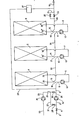
- the drawing shows an apparatus comprising three membrane filtration units 1, 2 and 3 which are aligned in series.
- Each membrane filtration unit comprises a number of pressure supporting pipes known per se, the inner side of said pipes being provided with a non woven tube supporting on its inner side a filtration membrane.
- Said filtration membrane may consist of cellulose acetate, but also of other macromolecular substances. It will be obvious, however, that instead of pressure supporting pipes, a helically wound membrane filtration unit may be accommodated in the membrane filtration units, said helically wound unit then serving for the purification of liquid to be purified.
- the membrane filtration unit 1 is, through membrane filtration unit outlet 35, connected with a circuit 6, which circuit 6 debouches into the membrane filtration unit inlet 36.
- the membrane filtration unit 2 is, through membrane filtration unit outlet 35', connected with circuit 7, which in turn is connected with the membrane filtration unit 2 through membrane filtration unit inlet 36'.
- membrane filtration unit 3 is, through outlet 35", connected with circuit 8, which debouches into membrane filtration unit inlet 36".
- Each circuit 6, 7, 8 comprises a circulation pump 12, which pumps liquid through the circuit and the membrane filtration unit connected therewith.
- Circuit 6 connected with the first membrane filtration unit 1, is provided with a circuit inlet 9 and a circuit outlet 13. Said circuit outlet 13 is located between the membrane filtration unit outlet 35, and the circulation pump 12, whereas the circuit inlet 9 is situated between said circuit outlet 13 and said circulation pump 12.
- a continuous line part 16 is accommodated in between the circuit inlet 9 and the circuit outlet 13, thus causing a closed circuit 6 to be obtained.
- the circuit outlet 13 of the first circuit 6 is connected with the circuit outlet 10 of the second circuit 7, through line 33, said second circuit 7 being likewise provided with a second circuit outlet 14.
- the inlet 10 and the outlet 14 of the second circuit 7 are provided in a manner identical to that of the circuit inlet 9 and the circuit outlet 13 in the first circuit 6.
- the outlet 14 and the inlet 10 of the second circuit 7 are interconnected through line part 17.
- the outlet 14 of the second circuit debouches, through line 34, into the inlet 11 of the third circuit 8, which third circuit 8 is likewise provided with an outlet 15 being connected with an outlet line 19, in which a close-off valve 22 is accommodated.
- the outlet line 19 is connected with a line 21 debouching at either side of the close -off valve 22 into line 19.
- Said line 21 further comprises a close-off valve 20.
- the inlet 11 and the outlet 15 of the third circuit 8 are interconnected through line part 18.
- Inlet 9 of the first circuit 6 is connected with a main supply line, being connected in turn with a high pressure pump 32, which high pressure pump is in turn connected with a liquid supply line 3' for the supply of liquid to be purified.
- Lines 3' comprises a close-off valve 4.
- the apparatus further comprises a washing liquid inlet 23, adjoining a washing liquid inlet pump 24 in the form of a centrifugal pump, which centrifugal pump adjoins a line 25 debouching into a branch line 27, which, through line part 28, debouches into supply inlet line 3' in between the said close-off valve 4 and the high pressure pump 32, while, on the other hand, line 25 debouchesinto supply line 5 through line part 26, comprising a close-off valve 30.
- Centrifugal pump 24 for washing liquid is actuated when close-off valves 30 and 31 are closed, so that line 25 is filled with washing liquid.
- Said washing liquid subsequently streams through branch line part 27 towards close-off valve 31, which valve 31 is opened by the relative pressure, whilst simultaneously liquid inlet valve 4 is closed.
- close-off valve 30 is opened, so that washing liquid supplied through line part 28 and line part 26, streams into inlet line 5.
- the quantity of washing liquid fed into circuit inlet 9, is chosen in such a way that the fed quantity of washing liquid exceeds the predetermined pumping capacity of the circulation pump 12.
- washing liquid will move, through connection line part 16, towards circuit outlet 13, while, on the other hand, circulation pump 12 will pump the incoming liquid through inlet 9, through the first membrane filtration unit 1.
- the washing liquid After having passed said membrane filtration unit 1 through outlet 35 the washing liquid will flow away through circuit outlet 13 of the first circuit 6 and will subsequently flow through line 33 into inlet 10 of the second circuit 7.
- inlet 10 is also fed with a quantity of washing liquid, which exceeds the predetermined capacity of the circulation pump 12.
- the circulation pump 12 of the second circuit 7 also pumps the washing liquid through the second membrane filtration unit 2, which washing liquid will escape through membrane filtration unit outlet 35' and circuit outlet 14 of the second circuit 7.
- washing liquid Since inlet 10 is fed with a quantity of washing liquid, which exceeds the pumping capacity of circulation pump 12, washing liquid will also flow towards outlet 14, through line 17. Consequently excess liquids will be expelled by washing liquid in a very convenient manner. Washing liquid discharged through outlet 14 of second circuit 7, flows through line 34, into inlet 11 of third circuit 8 and after having passed third membrane filtration unit 3, subsequently flows through outlet 15 of third circuit 8. Said removal of washing liquid may easily take place by opening the close-off valves 20 and 22. As the quantity of washing liquid being introduced into inlet 11 of the third circuit 8, also exceeds the pumping capacity of circulation pump 12, which is accommodated in third circuit 8, washing liquid will flow through connection line 18, towards outlet 15. of third circuit 8. The washing liquid escaping through outlet 15, will arrive in line 19.
- the high pressure pump 32 may proceed its action, as in the apparatus according to the invention, high pressure cannot possibly be exerted due to close-off valves 20 and 22 being opened.
- said high pressure pump may be stopped during a further washing operation.
- washing liquid is fed into inlets-9, 10 or 11 such, that approximately 5 to 10% of the fed quantity of washing liquid will - stream towards outlet 13, 14, 15 respectively, through connection lines 16, 17, 18, respectively.
- the remaining washing liquid is pumped through the consecutive membrane filtration units 1, 2, 3 respectively, by the circulation pumps 12.
- the washing liquid is fed by means of, for example, a centrifugal pump exerting a pressure of e.g. 3 atm., whilst said centrifugal pump, being operable during the membrane filtration, is able to exert pressures in the system of e.g. 38 atm.
- a centrifugal pump exerting a pressure of e.g. 3 atm.
- said centrifugal pump being operable during the membrane filtration, is able to exert pressures in the system of e.g. 38 atm.
- the latter is of course, dependent upon opening or closing the close-off valves 20, 22, respectively.
- the close-off valves 30 and 31 are closed and liquid inlet 4 is re-opened whilst close-off valve 22 in outlet line 19 is closed as well. Since less washing liquid may escape through close-off valve 20, than through both close-off valves 20 and 22 together, said washing liquid will be subjected to a high pressure when high pressure pump 32 is operating.
- the fed liquid to be purified is streaming through line 3' and arrives through line 5 into inlet 9 of the first circuit 6, : whereafter said liquid is circulated by the circulation pump.
- said circulating pumping permeate passes the membranes, whereafter more impure liquid escapes through line 33 towards second circuit 7 and after having passed the second membrane filtration unit 2, still more impure liquid will stream into third circuit 8, through line 34.
- the pumping capacity of the circulation pumps 12 is e.g. 123 cm3/h, whilst the capacity of the centrifugal pump 24 is 130 m3/h.
- the high pressure pump has, for instance, a capacity ranging from 23 to 40 m3/h and is able to increase the pressure of liquid to be purified, from 15 to 38 atm.
- said cleaning bodies may be fed through line 29, and after having passed the entire installation said bodies may be recovered in a cleaning body storage vessel 37 and, starting again from said vessel 37, be re-introduced into line 5.
- a chemical cleaning agent or a desinfectdnt may be added to the washing liquid.
- an additional washing liquid inlet pump 24 is used for supplying an amount of washing liquid to the circuit which amount is greater than the amount of liquid pumped by circuit pump 12 under normal working conditions.
- the washing operation takes place at a low pressure and with a high flow velocity, the washing is very effective, so that a smaller number of washing operations per day are necessary.
Abstract
Description
- The present invention relates to a method of washing and cleaning a plurality of membrane filtration units, aligned in series, each of said units being part of a circuit pro- . vided with a circulation pump, whereby the respective unit of each of the circuits can be fed with liquid to be purified and impure liquid may be discharged, which either serves as a supply for consecutive circuit or which is discharged, by subsequently introducing a washing liquid whether or not containing washing bodies, through membrane filtration units, aligned in series.
- A method of this type for washing and cleaning a plurality of membrane filtration units aligned in series, is known in the art. During the use of membrane filtration units, impurities will accumulate upon the membrane surface, which surface contacts liquids to be purified; the presence of said impurities may give rise to a decrease of the action of the membranes. In order to remove said impurities a constant washing and cleaning of said membranes in membrane filtration units is required.
- Often said washing and cleaning is effected with a desinfectant in order to prevent microbiological growth in the membrane filtration units, said accumulation being due to high temperatures occurring during said membrane filtrations, due to which the growth of microbes will rapidly multiply, which growth may likewise give rise to a great number of other disadvantageous effects.
- The washing and cleaning effects may be improved in tubular membranes by including spherical bodies in the washing liquids, which bodies exert a mechanical cleaning action upon membranes. In membrane units consisting of helically wound membrane modules, only washing liquid is used which may contain a desinfectant in a later stage.
- In this known method of washing a plurality of membaane filtration units aligned in series, the disadvantage occurs thai special measures have to be taken for separating the washing: liquid for the various membrane filtration units aligned in series, so, special close-off valves have to be applied in order to introduce the washing liquids through various different consecutive membrane filtration units. Furthermore, said known method of washing membrane filtration units demands much energy.
- The present invention aims to provide a method of and apparatus for washing and cleaning a plurality of filtration units aligned in series, whereby the aforementioned disadvantages do not occur.
- This object is attained in accordance with the present invention in that a quantity of washing liquids is fed to the circuits which exceeds the predetermined pumping capacity of the circulation pump.
- When such a measure is applied the circulation pump will pump the washing liquids entirely through the membrane filtration unit without particular close-off valves having to be opened or closed in order to effect the washing liquid to be discharged after it has passed the respective membrane filtration unit.
- This allows a very easy conversion from the normal working conditions to the washing operation and from the washing operation to normal working conditions.
- As the present installation now comprises less valves, said installation will be less expensive and less susceptible to interruptions; moreover the control of the valves is effected more easily.
- The amount of required washing liquid is also smaller, as the change to the washing operation can be effected more rapidly.
- The flow velocity during washing is high and thus washing can be performed in a short period of time, which involves less temperature decrease of the installation and a smaller consumption of cleaning agents. The fact that the temperature of the present installation is substantially maintained is very important, as cleaning with enzymes containing washing liquids requires a very limited temperature range for an effective action of said enzymes.
- In this respect it should be noted that a temperature decrease of the installation is avoided by the fact that the circuit pumps remain in active condition and dissipate heat.
- The washing liquid is preferably fed to the circuit at a point located between the circulation pump inlet and the outlet of the respective unit being connected with the circuit, whilst on the other hand, said washing liquid is discharged from the circuit at a location situated between the washing liquid inlet and the outlet of the respective membrane filtration unit. Due to this measure the circulation pump will only pump washing liquid through the membrane filtration unit, whilst said pump will redischarge said washing liquid from the circuit, after said liquid has passed the relative membrane filtration unit, so that the washing liquid cannot possibly be re-introduced into said circulation pump. The excess washing liquid will actually cause part of the washing liquid to flow from the inlet towards the washing liquid outlet of the circuit. Due to these measures, an optimum cleaning of the membrane filtration units is obtained.
- The present invention also comprises an apparatus for washing and cleaning a plurality of membrane filtration units aligned ' in series, each of said units being accommodated in a circuit' comprising a circulation pump, each circuit being provided with a circuit inlet for feeding a liquid to be purified into the respective units and a circuit outlet for the discharge of impure liquid from the circuit, which circuit outlet is connected with a consecutive circuit or with an apparatus outlet and a washing liquid inlet, said apparatus comprising a washing liquid inlet pump having a pumping capacity exceeding that of the predetermined pumping capacity of the circulation pump of a circuit into which washing liquid is fed.
- As far as in the foregoing the expression membrane filtration units is used, such expression is to be understood as units which are employed for ultrafiltration and units which are employed for reverse osmosis.
- The present invention will be explained with respect to an embodiment in the drawing, which schematically shows an apparatus for performing the method in accordance with the present invention.
- The drawing shows an apparatus comprising three
membrane filtration units 1, 2 and 3 which are aligned in series. 'Each membrane filtration unit comprises a number of pressure supporting pipes known per se, the inner side of said pipes being provided with a non woven tube supporting on its inner side a filtration membrane. Said filtration membrane may consist of cellulose acetate, but also of other macromolecular substances. It will be obvious, however, that instead of pressure supporting pipes, a helically wound membrane filtration unit may be accommodated in the membrane filtration units, said helically wound unit then serving for the purification of liquid to be purified. - The membrane filtration unit 1 is, through membrane
filtration unit outlet 35, connected with acircuit 6, whichcircuit 6 debouches into the membranefiltration unit inlet 36. As can be seen themembrane filtration unit 2 is, through membrane filtration unit outlet 35', connected withcircuit 7, which in turn is connected with the membrane filtration unit2through membrane filtration unit inlet 36'. - Finally membrane filtration unit 3 is, through
outlet 35", connected with circuit 8, which debouches into membranefiltration unit inlet 36". - Each
circuit circulation pump 12, which pumps liquid through the circuit and the membrane filtration unit connected therewith. -
Circuit 6, connected with the first membrane filtration unit 1, is provided with acircuit inlet 9 and acircuit outlet 13. Saidcircuit outlet 13 is located between the membranefiltration unit outlet 35, and thecirculation pump 12, whereas thecircuit inlet 9 is situated between saidcircuit outlet 13 and saidcirculation pump 12. - A
continuous line part 16 is accommodated in between thecircuit inlet 9 and thecircuit outlet 13, thus causing a closedcircuit 6 to be obtained. - The
circuit outlet 13 of thefirst circuit 6 is connected with thecircuit outlet 10 of thesecond circuit 7, throughline 33, saidsecond circuit 7 being likewise provided with asecond circuit outlet 14. Theinlet 10 and theoutlet 14 of thesecond circuit 7 are provided in a manner identical to that of thecircuit inlet 9 and thecircuit outlet 13 in thefirst circuit 6. Theoutlet 14 and theinlet 10 of thesecond circuit 7 are interconnected throughline part 17. - The
outlet 14 of the second circuit debouches, throughline 34, into theinlet 11 of the third circuit 8, which third circuit 8 is likewise provided with anoutlet 15 being connected with anoutlet line 19, in which a close-offvalve 22 is accommodated. Theoutlet line 19 is connected with aline 21 debouching at either side of the close -offvalve 22 intoline 19. Saidline 21 further comprises a close-offvalve 20. - The
inlet 11 and theoutlet 15 of the third circuit 8 are interconnected throughline part 18. -
Inlet 9 of thefirst circuit 6 is connected with a main supply line, being connected in turn with ahigh pressure pump 32, which high pressure pump is in turn connected with a liquid supply line 3' for the supply of liquid to be purified. Lines 3' comprises a close-off valve 4. - The apparatus further comprises a washing
liquid inlet 23, adjoining a washingliquid inlet pump 24 in the form of a centrifugal pump, which centrifugal pump adjoins aline 25 debouching into abranch line 27, which, throughline part 28, debouches into supply inlet line 3' in between the said close-off valve 4 and thehigh pressure pump 32, while, on the other hand,line 25debouchesinto supply line 5 throughline part 26, comprising a close-offvalve 30. - In order to wash and clean membrane filtration units, one proceeds as follows.
-
Centrifugal pump 24 for washing liquid is actuated when close-offvalves 30 and 31 are closed, so thatline 25 is filled with washing liquid. Said washing liquid subsequently streams throughbranch line part 27 towards close-off valve 31, which valve 31 is opened by the relative pressure, whilst simultaneously liquid inlet valve 4 is closed. After having closed said liquid inlet valve 4, close-offvalve 30 is opened, so that washing liquid supplied throughline part 28 andline part 26, streams intoinlet line 5. The quantity of washing liquid fed intocircuit inlet 9, is chosen in such a way that the fed quantity of washing liquid exceeds the predetermined pumping capacity of thecirculation pump 12. Thus a part of the washing liquid will move, throughconnection line part 16, towardscircuit outlet 13, while, on the other hand,circulation pump 12 will pump the incoming liquid throughinlet 9, through the first membrane filtration unit 1. After having passed said membrane filtration unit 1 throughoutlet 35 the washing liquid will flow away throughcircuit outlet 13 of thefirst circuit 6 and will subsequently flow throughline 33 intoinlet 10 of thesecond circuit 7. As substantially no liquid can escape through the membranes, since a washing liquid having a relatively low pressure is used,inlet 10 is also fed with a quantity of washing liquid, which exceeds the predetermined capacity of thecirculation pump 12. Thecirculation pump 12 of thesecond circuit 7 also pumps the washing liquid through the secondmembrane filtration unit 2, which washing liquid will escape through membrane filtration unit outlet 35' andcircuit outlet 14 of thesecond circuit 7. Sinceinlet 10 is fed with a quantity of washing liquid, which exceeds the pumping capacity ofcirculation pump 12, washing liquid will also flow towardsoutlet 14, throughline 17. Consequently excess liquids will be expelled by washing liquid in a very convenient manner. Washing liquid discharged throughoutlet 14 ofsecond circuit 7, flows throughline 34, intoinlet 11 of third circuit 8 and after having passed third membrane filtration unit 3, subsequently flows throughoutlet 15 of third circuit 8. Said removal of washing liquid may easily take place by opening the close-offvalves inlet 11 of the third circuit 8, also exceeds the pumping capacity ofcirculation pump 12, which is accommodated in third circuit 8, washing liquid will flow throughconnection line 18, towardsoutlet 15. of third circuit 8. The washing liquid escaping throughoutlet 15, will arrive inline 19. - During the washing and cleaning operation the
high pressure pump 32 may proceed its action, as in the apparatus according to the invention, high pressure cannot possibly be exerted due to close-offvalves - It goes without saying that said high pressure pump may be stopped during a further washing operation.
- It is generally recommended to choose the quantity of washing liquid to be fed into inlets-9, 10 or 11 such, that approximately 5 to 10% of the fed quantity of washing liquid will - stream towards
outlet connection lines membrane filtration units 1, 2, 3 respectively, by the circulation pumps 12. - The washing liquid is fed by means of, for example, a centrifugal pump exerting a pressure of e.g. 3 atm., whilst said centrifugal pump, being operable during the membrane filtration, is able to exert pressures in the system of e.g. 38 atm. The latter is of course, dependent upon opening or closing the close-off
valves - After having washed and cleaned the entire installation, the close-off
valves 30 and 31 are closed and liquid inlet 4 is re-opened whilst close-offvalve 22 inoutlet line 19 is closed as well. Since less washing liquid may escape through close-offvalve 20, than through both close-offvalves high pressure pump 32 is operating. The fed liquid to be purified is streaming through line 3' and arrives throughline 5 intoinlet 9 of thefirst circuit 6, : whereafter said liquid is circulated by the circulation pump. During said circulating pumping permeate passes the membranes, whereafter more impure liquid escapes throughline 33 towardssecond circuit 7 and after having passed the secondmembrane filtration unit 2, still more impure liquid will stream into third circuit 8, throughline 34. - It will be obvious that instead of three membrane filtration units, a greater or smaller number may be employed.
- The pumping capacity of the circulation pumps 12 is e.g. 123 cm3/h, whilst the capacity of the
centrifugal pump 24 is 130 m3/h. - 32 The high pressure pump has, for instance, a capacity ranging from 23 to 40 m3/h and is able to increase the pressure of liquid to be purified, from 15 to 38 atm.
- From the foregoing it appears that by feeding a suitable quantity of washing liquid to
inlet 9, no special close-off valves need be accommodated inconnection lines circulation pump 12, will automatically arrive inoutlets connection lines - In case that the membranes should also be subjected to a cleaning action with mechanical means, like, for example, plastics spheres, said cleaning bodies may be fed through
line 29, and after having passed the entire installation said bodies may be recovered in a cleaningbody storage vessel 37 and, starting again from saidvessel 37, be re-introduced intoline 5. - If desired, a chemical cleaning agent or a desinfectdnt may be added to the washing liquid.
- For completeness' sake it is observed that, when 130 m3/h of liquid is fed to the
first circuit 6, the same quantities may be fed to the second andthird circuit 2, 3, respectively. Thecirculation pump 12 in each circuit have a pumping capacity of 123 m3/h. - As the washing with washing liquid is executed at low pressure, a back flush effect is observed involving a loosening of the layer of impurities on the membranes,-while on the other hand a better removal of said impurities is effected.
- In the preceding description an additional washing
liquid inlet pump 24 is used for supplying an amount of washing liquid to the circuit which amount is greater than the amount of liquid pumped bycircuit pump 12 under normal working conditions. - However, it is also possible to obtain the desired effect by decreasing the capacity of
circuit pump 12 until said capacity is lower than the capacity of thehigh pressure pump 32. For obtaining a decreased pressure during the cleaning operation with washing liquid thevalves end outlet 19 have to be more opened. - As in the present invention the washing operation takes place at a low pressure and with a high flow velocity, the washing is very effective, so that a smaller number of washing operations per day are necessary.
- Due to the short washing time there is a higher tendency to perform an intermediate washing, the more so as the washing can be performed in about 180 seconds (2 x 90 seconds).
Claims (16)
that a quantity of washing liquid is fed to the circuits (6, 7, 8) which exceeds the predetermined pumping capacity of the circulation pump (22).
Priority Applications (1)
| Application Number | Priority Date | Filing Date | Title |
|---|---|---|---|
| AT80200614T ATE3185T1 (en) | 1979-07-03 | 1980-06-27 | METHOD AND APPARATUS FOR WASHING AND CLEANING MEMBRANE FILTRATION UNITS. |
Applications Claiming Priority (2)
| Application Number | Priority Date | Filing Date | Title |
|---|---|---|---|
| NL7905194 | 1979-07-03 | ||
| NLAANVRAGE7905194,A NL172405C (en) | 1979-07-03 | 1979-07-03 | METHOD AND APPARATUS FOR FLUSHING A NUMBER OF SERIAL FILTRATION UNITS FOR PERFORMING A MEMBRANE FILTRATION UNDER PRESSURE. |
Publications (3)
| Publication Number | Publication Date |
|---|---|
| EP0021547A2 true EP0021547A2 (en) | 1981-01-07 |
| EP0021547A3 EP0021547A3 (en) | 1981-01-14 |
| EP0021547B1 EP0021547B1 (en) | 1983-05-04 |
Family
ID=19833477
Family Applications (1)
| Application Number | Title | Priority Date | Filing Date |
|---|---|---|---|
| EP80200614A Expired EP0021547B1 (en) | 1979-07-03 | 1980-06-27 | Method of and apparatus for washing and cleaning membrane filtration units |
Country Status (6)
| Country | Link |
|---|---|
| US (1) | US4361485A (en) |
| EP (1) | EP0021547B1 (en) |
| JP (1) | JPS5631408A (en) |
| AT (1) | ATE3185T1 (en) |
| DE (1) | DE3062963D1 (en) |
| NL (1) | NL172405C (en) |
Families Citing this family (17)
| Publication number | Priority date | Publication date | Assignee | Title |
|---|---|---|---|---|
| US4857181A (en) * | 1986-10-30 | 1989-08-15 | Cobe Laboratories, Inc. | Control of cleaning of dialysate preparation apparatus |
| US4784771A (en) * | 1987-08-03 | 1988-11-15 | Environmental Water Technology, Inc. | Method and apparatus for purifying fluids |
| JPH0657304B2 (en) * | 1988-12-27 | 1994-08-03 | 三浦工業株式会社 | Membrane modular water treatment system |
| JPH02174919A (en) * | 1988-12-27 | 1990-07-06 | Miura Co Ltd | Membrane module type water treating device |
| US5143601A (en) * | 1989-10-06 | 1992-09-01 | Water Factory Corporation | Fluid purification system |
| US5434381A (en) * | 1993-09-13 | 1995-07-18 | T-Star Industrial Electronics, Inc. | Apparatus for filtering machining liquid of an electrical discharge machine |
| JPH08108048A (en) * | 1994-10-12 | 1996-04-30 | Toray Ind Inc | Reverse osmosis separator and reverse osmosis separating method |
| US5772624A (en) | 1995-07-20 | 1998-06-30 | Medisystems Technology Corporation | Reusable blood lines |
| EP1329425A1 (en) * | 2002-01-18 | 2003-07-23 | Toray Industries, Inc. | Desalination method and desalination apparatus |
| US7368139B1 (en) * | 2002-03-15 | 2008-05-06 | Bronnert Herve X | Aseptic processing system for fruit filling |
| US7632410B2 (en) * | 2003-08-21 | 2009-12-15 | Christopher Heiss | Universal water purification system |
| US7291267B2 (en) * | 2004-01-30 | 2007-11-06 | Ljc Technologies, L.L.C. | Molecular separator |
| KR100595408B1 (en) * | 2005-12-14 | 2006-07-04 | 김인석 | Tunnel lighting fixture |
| US8119008B2 (en) * | 2006-07-10 | 2012-02-21 | Christopher Heiss | Fluid purification methods and devices |
| WO2009009465A1 (en) * | 2007-07-06 | 2009-01-15 | Christopher William Heiss | Electrocoagulation reactor and water treatment system and method |
| US20110049049A1 (en) * | 2009-09-03 | 2011-03-03 | General Electric Company | Water purification system skid |
| US20130146541A1 (en) * | 2011-12-13 | 2013-06-13 | Nxstage Medical, Inc. | Fluid purification methods, devices, and systems |
Citations (5)
| Publication number | Priority date | Publication date | Assignee | Title |
|---|---|---|---|---|
| US3493495A (en) * | 1968-01-17 | 1970-02-03 | Morris Mendelson | Apparatus and process for the osmotic separation of water from a saline solution |
| GB1250482A (en) * | 1968-03-19 | 1971-10-20 | ||
| US3756408A (en) * | 1972-06-15 | 1973-09-04 | Osmonics Inc | Separation system |
| NL7404264A (en) * | 1974-03-28 | 1975-09-30 | Wafilin Bv | Membrane filtration of potato water - in which the membrane is periodically or continuously sterilised to reduce smell |
| NL7404265A (en) * | 1974-03-28 | 1975-09-30 | Wafilin Bv | Membrane filtration in series of units - where the feed is switched periodically to the last unit to cool and clean it |
Family Cites Families (5)
| Publication number | Priority date | Publication date | Assignee | Title |
|---|---|---|---|---|
| US3498910A (en) * | 1968-09-03 | 1970-03-03 | Morris Mendelson | Apparatus and process for the controlled osmotic separation of water from sea water |
| JPS4831774A (en) * | 1971-08-26 | 1973-04-26 | ||
| US3846295A (en) * | 1972-04-06 | 1974-11-05 | Ultrascience Inc | Method and apparatus for use in water purification by reverse osmosis |
| JPS50109179A (en) * | 1974-02-06 | 1975-08-28 | ||
| US4200533A (en) * | 1978-06-28 | 1980-04-29 | Brandon Craig A | Hyperfiltration apparatus and method of fluid treatment |
-
1979
- 1979-07-03 NL NLAANVRAGE7905194,A patent/NL172405C/en not_active IP Right Cessation
-
1980
- 1980-06-27 DE DE8080200614T patent/DE3062963D1/en not_active Expired
- 1980-06-27 EP EP80200614A patent/EP0021547B1/en not_active Expired
- 1980-06-27 AT AT80200614T patent/ATE3185T1/en active
- 1980-07-01 US US06/165,042 patent/US4361485A/en not_active Expired - Lifetime
- 1980-07-03 JP JP9160780A patent/JPS5631408A/en active Granted
Patent Citations (5)
| Publication number | Priority date | Publication date | Assignee | Title |
|---|---|---|---|---|
| US3493495A (en) * | 1968-01-17 | 1970-02-03 | Morris Mendelson | Apparatus and process for the osmotic separation of water from a saline solution |
| GB1250482A (en) * | 1968-03-19 | 1971-10-20 | ||
| US3756408A (en) * | 1972-06-15 | 1973-09-04 | Osmonics Inc | Separation system |
| NL7404264A (en) * | 1974-03-28 | 1975-09-30 | Wafilin Bv | Membrane filtration of potato water - in which the membrane is periodically or continuously sterilised to reduce smell |
| NL7404265A (en) * | 1974-03-28 | 1975-09-30 | Wafilin Bv | Membrane filtration in series of units - where the feed is switched periodically to the last unit to cool and clean it |
Non-Patent Citations (1)
| Title |
|---|
| BETRIEBSTECHNIK, Vol. 16, No. 5, 1975 Groefelfing, DE K. MARQUARDT: "Reinigung olhaltiger Abwasser", pages 11-14. * |
Also Published As
| Publication number | Publication date |
|---|---|
| NL172405B (en) | 1983-04-05 |
| NL7905194A (en) | 1980-11-28 |
| ATE3185T1 (en) | 1983-05-15 |
| JPH0255098B2 (en) | 1990-11-26 |
| EP0021547A3 (en) | 1981-01-14 |
| JPS5631408A (en) | 1981-03-30 |
| US4361485A (en) | 1982-11-30 |
| EP0021547B1 (en) | 1983-05-04 |
| NL172405C (en) | 1983-09-01 |
| DE3062963D1 (en) | 1983-06-09 |
Similar Documents
| Publication | Publication Date | Title |
|---|---|---|
| EP0021547B1 (en) | Method of and apparatus for washing and cleaning membrane filtration units | |
| CN102802769B (en) | Filtering method, and membrane-filtering apparatus | |
| KR102180787B1 (en) | Water treatment system and method by reverse osmosis or nanofiltration | |
| JPH06277664A (en) | Method and apparatus for clarifying surface flowing water with membrane | |
| KR20090127124A (en) | Drain-flush sequence and system for filter module | |
| US4255255A (en) | Tubular membrane separation process and apparatus therefor | |
| US3493495A (en) | Apparatus and process for the osmotic separation of water from a saline solution | |
| JPH11156166A (en) | Cleaning method for hollow fiber membrane module | |
| JP4439526B2 (en) | Method for complete filtration of products and apparatus for carrying out this method | |
| HU217640B (en) | Process and device for concentrating solid/liquid mixtures, especially fruit juice by membrane technology | |
| RU2440180C2 (en) | Method processing detergents and device to this end | |
| CN113476942A (en) | Filter backwashing system, process and control method | |
| EP0669159A1 (en) | Back wash method for filtration modules using internally pressurized hollow fibers | |
| JP4882164B2 (en) | Membrane filtration device | |
| US3812969A (en) | Apparatus for fluid treatment | |
| US5783245A (en) | Method and apparatus for processing dairy product | |
| JP3615918B2 (en) | Method and apparatus for cleaning reverse osmosis membrane module | |
| RU2323036C2 (en) | Method and device for concentrating water solutions of biology-active agents | |
| HU218810B (en) | Process and device for concentrating solid-liquid mixtures by means of diaphragm technology | |
| CN219518405U (en) | Material concentration system | |
| JP4062585B2 (en) | Membrane separation wastewater treatment equipment | |
| WO2009122460A1 (en) | Method and apparatus for cleaning membrane module | |
| JP2014151304A (en) | Back washing filtration apparatus and deposit removing method for filtration element | |
| CN108031291A (en) | A kind of multifunctional membrane filtration system | |
| JP3460322B2 (en) | Backwashing method for membrane separation device using internal pressure type tubular membrane module |
Legal Events
| Date | Code | Title | Description |
|---|---|---|---|
| PUAI | Public reference made under article 153(3) epc to a published international application that has entered the european phase |
Free format text: ORIGINAL CODE: 0009012 |
|
| PUAL | Search report despatched |
Free format text: ORIGINAL CODE: 0009013 |
|
| AK | Designated contracting states |
Designated state(s): AT BE CH DE FR GB IT LU NL SE |
|
| AK | Designated contracting states |
Designated state(s): AT BE CH DE FR GB IT LU NL SE |
|
| 17P | Request for examination filed |
Effective date: 19801118 |
|
| ITF | It: translation for a ep patent filed |
Owner name: BARZANO' E ZANARDO MILANO S.P.A. |
|
| GRAA | (expected) grant |
Free format text: ORIGINAL CODE: 0009210 |
|
| AK | Designated contracting states |
Designated state(s): AT BE CH DE FR GB IT LI LU NL SE |
|
| REF | Corresponds to: |
Ref document number: 3185 Country of ref document: AT Date of ref document: 19830515 Kind code of ref document: T |
|
| REF | Corresponds to: |
Ref document number: 3062963 Country of ref document: DE Date of ref document: 19830609 |
|
| PGFP | Annual fee paid to national office [announced via postgrant information from national office to epo] |
Ref country code: LU Payment date: 19830621 Year of fee payment: 4 |
|
| PG25 | Lapsed in a contracting state [announced via postgrant information from national office to epo] |
Ref country code: LU Free format text: LAPSE BECAUSE OF NON-PAYMENT OF DUE FEES Effective date: 19830630 |
|
| ET | Fr: translation filed | ||
| PLBE | No opposition filed within time limit |
Free format text: ORIGINAL CODE: 0009261 |
|
| STAA | Information on the status of an ep patent application or granted ep patent |
Free format text: STATUS: NO OPPOSITION FILED WITHIN TIME LIMIT |
|
| 26N | No opposition filed | ||
| GBPR | Gb: patent revoked under art. 102 of the ep convention designating the uk as contracting state | ||
| PGFP | Annual fee paid to national office [announced via postgrant information from national office to epo] |
Ref country code: CH Payment date: 19910528 Year of fee payment: 12 |
|
| PGFP | Annual fee paid to national office [announced via postgrant information from national office to epo] |
Ref country code: AT Payment date: 19910627 Year of fee payment: 12 |
|
| ITTA | It: last paid annual fee | ||
| PG25 | Lapsed in a contracting state [announced via postgrant information from national office to epo] |
Ref country code: AT Effective date: 19920627 |
|
| PG25 | Lapsed in a contracting state [announced via postgrant information from national office to epo] |
Ref country code: LI Effective date: 19920630 Ref country code: CH Effective date: 19920630 |
|
| REG | Reference to a national code |
Ref country code: GB Ref legal event code: 732 |
|
| REG | Reference to a national code |
Ref country code: CH Ref legal event code: PL |
|
| EAL | Se: european patent in force in sweden |
Ref document number: 80200614.8 |
|
| PGFP | Annual fee paid to national office [announced via postgrant information from national office to epo] |
Ref country code: SE Payment date: 19950515 Year of fee payment: 16 |
|
| PGFP | Annual fee paid to national office [announced via postgrant information from national office to epo] |
Ref country code: GB Payment date: 19950516 Year of fee payment: 16 |
|
| PGFP | Annual fee paid to national office [announced via postgrant information from national office to epo] |
Ref country code: DE Payment date: 19950519 Year of fee payment: 16 |
|
| PGFP | Annual fee paid to national office [announced via postgrant information from national office to epo] |
Ref country code: BE Payment date: 19950607 Year of fee payment: 16 |
|
| PGFP | Annual fee paid to national office [announced via postgrant information from national office to epo] |
Ref country code: FR Payment date: 19950628 Year of fee payment: 16 |
|
| PGFP | Annual fee paid to national office [announced via postgrant information from national office to epo] |
Ref country code: NL Payment date: 19950629 Year of fee payment: 16 |
|
| PG25 | Lapsed in a contracting state [announced via postgrant information from national office to epo] |
Ref country code: GB Effective date: 19960627 |
|
| PG25 | Lapsed in a contracting state [announced via postgrant information from national office to epo] |
Ref country code: SE Effective date: 19960628 |
|
| PG25 | Lapsed in a contracting state [announced via postgrant information from national office to epo] |
Ref country code: BE Effective date: 19960630 |
|
| BERE | Be: lapsed |
Owner name: WAFILIN B.V. Effective date: 19960630 |
|
| PG25 | Lapsed in a contracting state [announced via postgrant information from national office to epo] |
Ref country code: NL Effective date: 19970101 |
|
| GBPC | Gb: european patent ceased through non-payment of renewal fee |
Effective date: 19960627 |
|
| PG25 | Lapsed in a contracting state [announced via postgrant information from national office to epo] |
Ref country code: FR Effective date: 19970228 |
|
| PG25 | Lapsed in a contracting state [announced via postgrant information from national office to epo] |
Ref country code: DE Effective date: 19970301 |
|
| EUG | Se: european patent has lapsed |
Ref document number: 80200614.8 |
|
| NLV4 | Nl: lapsed or anulled due to non-payment of the annual fee |
Effective date: 19970101 |
|
| REG | Reference to a national code |
Ref country code: FR Ref legal event code: ST |