EP0018971B1 - P-ion controller and control of ionic concentration in a flow-line - Google Patents
P-ion controller and control of ionic concentration in a flow-line Download PDFInfo
- Publication number
- EP0018971B1 EP0018971B1 EP79900433A EP79900433A EP0018971B1 EP 0018971 B1 EP0018971 B1 EP 0018971B1 EP 79900433 A EP79900433 A EP 79900433A EP 79900433 A EP79900433 A EP 79900433A EP 0018971 B1 EP0018971 B1 EP 0018971B1
- Authority
- EP
- European Patent Office
- Prior art keywords
- reagent
- sensors
- set forth
- orifices
- flow stream
- Prior art date
- Legal status (The legal status is an assumption and is not a legal conclusion. Google has not performed a legal analysis and makes no representation as to the accuracy of the status listed.)
- Expired
Links
Images
Classifications
-
- G—PHYSICS
- G05—CONTROLLING; REGULATING
- G05D—SYSTEMS FOR CONTROLLING OR REGULATING NON-ELECTRIC VARIABLES
- G05D21/00—Control of chemical or physico-chemical variables, e.g. pH value
- G05D21/02—Control of chemical or physico-chemical variables, e.g. pH value characterised by the use of electric means
Definitions
- tanks are more expensive than (plug-flow) pipeline, and turbine mixers not only more expensive but also more vulnerable than passive mixers.
- the present invention intends to reduce the "complex system of instruments" to a compact, effective system giving accurate pH or pion control in the process line with its inherent plug flow, at least as satisfactory as previously possible with mixing tanks and active mixers.
- a method of controlling ionic characteristics in a flow line having a stream flowing therein comprising the steps of distributing a pattern of pH or pion sensors having an inherent logarithmic analog output over the cross-sectional area of the flow line to generate individual sensor signals in response to the characteristics detected by each of the sensors, converting each of the signals to its antilogarithms, digitizing the signals before or after conversion to antilogarithms, averaging all the antilogarithms, converting the average antilogarithm to a binary control word, providing reagent orifices downstream of the sensors in a pattern distributed across the cross section of the flow stream, controlling the release of the reagent to the orifices from individual reagent dispensers in accordance with the binary control word, and mixing the flow stream downstream of the reagent orifices to homogenize it.
- an apparatus for controlling the ionic characteristics of a stream of liquid flowing in a line comprising an array of pH of P-ion sensors having an inherent logarithmic analog output distributed across the cross section of the line, each of the sensors being connected to an individual antilogging means, the array of antilogging means being connected to an averaging means, with a digitizing means being connected either between the sensors and the antilogging means or between the antilogging means and the averaging means, the averaging means being connected to a binary signal generating means for providing a binary control word, a system for dispensing reagent including an array of orifices distributed over the cross section of the flow stream downstream of the sensors, an array of reagent dispensers connected to the reagent orifice array, control means connecting each of the dispensers to the binary control word generating means for controlling the release of the reagent from each of the dispensers in accordance with the characteristics detected by the sensors, and mixing means in the line downstream of the reagent orifices to homogen
- the present invention consists of a number of steps, some of which are separately applicable in other situations, which speed up the necessary mass transfer operations to the degree required for successful total control of the reaction directly performed in the process line itself.
- This line may be a pipe, or a ditch as is common in wastewater processing.
- an orifice flowmeter is designated by 1.
- any accurate flowmeter with electrical signal output may be used.
- the process line is an open ditch, a metering flume will be more appropriate.
- 2 designates a static mixer of the backmixing type, symbolized by a bed of "Raschig Rings". These rings are sections of thin-walled tubing, about as high as they are wide. Such a bed not only repeatedly splits and joins separate stream threads of the process liquid, but within the cavities of the rings some process liquid is retained and released at a slower rate than the average process flow rate, producing the effect of backmixing. The end result is that a step- change of composition in the process stream is stretched into a ramp-change of composition, radially homogeneous from pipe-wall to pipeline center, rather than with a parabolic front as in plug flow.
- a grid across the process line carrying a number of composition sensors is designated by 3. These sensors have to operate reliably under total immersion under some ambient over-pressure.
- the sensors should be positioned such that shear flow across their sensitive faceplate maximizes fast response.
- the grid supporting the sensors may be followed by or be made part of, the distribution system which dispenses reagent evenly over the cross-section of the process stream, as shown by 4. It is advantageous to create local turbulence in the process liquid at the dispensing orifices in order to speed up the adjustment reaction between reagent and process liquid. Further mixing is enhanced by the non-backmixing static mixer 5.
- Such a static mixer is symbolized by a bed of spheres which split up and recombine the process stream without retention or backmixing, hence without introduction of deadtime between the reagent dispenser and the next grid of sensors.
- Various types of effective non-backmixing static mixers are commercially available.
- the static mixer 5 should be followed by the final sensor assembly 6 unless the control section is duplicated as discussed below.
- the sensors in grid 6 may be positioned as shown in grid 3, or in any different way which enhances shear flow of process liquid across their sensitive faceplates, as is shown in 6 by the use of flow deflectors.
- the final sensor-supporting grid also carries a reference electrode 7, again preferably of the type described in U.S. Patent No. 4,133,732, issued January 9, 1979 consisting of an electrode embedded in gelled endpoint-composition process liquid. By locating this reference electrode at the end of the composition-adjustment sections, there is minimum possibility of contamination of the reference gel in the long run. This reference electrode designates the base potential from which the signal potential of each of the many sensor electrodes is measured.
- mixer 5 and sensor grid 6 another reagent dispensing section containing elements 8, 9, and 10 which are identical to respective elements 3, 4 and 5 may be inserted to fine- tune process liquid composition adjustment.
- a third and fourth section dispensing a different type of reagent may be added also.
- the electrical composition-related signals put out by the sensors are processed electronically in a way to be discussed further down, to one signal going to the reagent dispensing control valves 11, 12, 13, ... 18, 19.
- This command signal is digital, and has the form of a binary number or "word". Such a number consists of the digits 1 and 0, wherein a 1 causes the solenoid of a specific on-off solenoid valve to be energized and the valve opened. The appearance of a 0 for that particular valve, de-energizes the solenoid and causes the valve to close.
- every digit in the word may command its own valve.
- valves are placed parallel to each other between a reagent reservoir under constant overpressure and the process line, and if each adjacent valve counting from the valve controlled by the least significant bit, is provided with an orifice which allows twice as much reagent to flow through as its smaller neighbor, every more significant bit in the control word commands a reagent flow twice as large as the flow commanded by its adjacent less significant bit.
- the total flow of the control valve assembly now becomes directly related to the total numerical value of the control command word. For example: a word of 10 binary digits or bits commands a total flow of from 0 to 1024 arbitrary units of flow although the diameters of the orifices in the 10 control valves only increase from 1 to 32 arbitrary length units.
- the subdivision in 10, or any other desired number of valves makes possible a very fast and very reproducible reagent flow control responding to commands for minute increases or decreases as fast as for large changes.
- Differential pressure controller 20 causes a constant pressure differential in the reagent liquid from reservoir 21 across the control valves to process line pressure at 22, e.g. by pressurizing the reagent reservoir with air.
- a flow of carrier liquid 23 insures rapid transportation of even small amounts of reagent to the dispensing orifices in the process line at 4.
- This carrier liquid may be water or process liquid from the process stream, moved by a separate pump.
- the drawing shows addition of controlled amount of liquid reagent.
- slurry or powdered solid reagents can be added to the carrier liquid by feeders with sequentially doubling capacities, controlled by a binary control word.
- the second, downstream, section may be fed from a similar control valve assembly 24, which now advantageously dispenses diluted reagent 25 from dilutor 26 in order to make possible a wider range of controlled reagent addition to the process stream.
- the reservoir of diluted reagent should be pressurized to a constant pressure differential over control valves 24, by differential pressure controller 27, just as was done with the previous control section.
- the second control section may advantageously narrow the final control range of the adjusted process liquid composition by using liquid reagent.
- the second, or any identical additional, control section may control the addition of a different reagent to correct a different deficiency in the process liquid, as e.g. acidic versus alkaline reagent in correcting the pH of the process stream which may be above as well as (at some other time) below the desired pH.
- the electrical signal derived from the sensors in that section will decide whether the section's reagent addition will be activated, or whether the pH calls for addition of different reagent from another section.
- the system of on-off control valves can shut off tight; something which should not be counted on with present-day control valves. Since leakage means extra chemicals to be neutralized, it represents waste.
- the electrical signal of the sensor electrodes has to be processed.
- Sensor electrodes by their nature have an output which is the logarithm of actual ionic concentration in the liquid to be measured. Should different electrode outputs, representing locally different ionic concentrations, be averaged directly by connecting in parallel, an average of the logarithms of ionic concentration differences would be obtained which mathematically may be called a geometric average. However, the actual difference in ion concentrations should be averaged by algebraic addition of these concentrations (and then division by the number of sensors), an operation of which the logarithm cannot be taken. Hence not geometrical, but arithmetical averaging is required. This refinement becomes meaningful if unbuffered process liquids have to be neutralized.
- the sensors should be positioned in such a way over the cross-section of the process line, that each represents a stream of process liquid of about equal volume.
- the averaged digital antilog output of the sensors lends itself directly to subtraction of the number of ion equivalents of reagent introduced into the process stream to produce the desired endpoint concentration; this output can also be multiplied by a variable factor, like process flow rate from flowmeter 1 or buffer capacity of the process liquid, computed from the downstream sensor response to a certain addition of reagent.
- All these computational manipulations of the averaged sensor signal, and its process into a valve command word of the proper format may be done inexpensively by microprocessor 29 for the first, and 30, for the second control section in the drawing.
- Modern electronic technology may allow combination of all operations done by separately presented circuit units 28, 29 and 30, in one VLSI (very large scale integrated circuit). This electronic processing is done momentary; in combination with the fast acting control valves, an inexpensive and sophisticated control action can be effected sufficiently fast to produce locally, on-line, the same satisfactory control as is obtained today with voluminous mixing tanks and active mixers, in batchwise control.
Abstract
Description
- Present-day technology for the adjustment of pH or pion in process- or waste-streams discourages in-line control; "A well-stirred tank which is easily controlled will always give more satisfactory results than a plug-flow process fitted with a complex system of instruments", F. G. Shinskey in: "pH and pion Control In Process And Waste Streams"; Wiley-Interscience, 1973; p. 242.
- However, tanks are more expensive than (plug-flow) pipeline, and turbine mixers not only more expensive but also more vulnerable than passive mixers. The present invention intends to reduce the "complex system of instruments" to a compact, effective system giving accurate pH or pion control in the process line with its inherent plug flow, at least as satisfactory as previously possible with mixing tanks and active mixers.
- Reactions which are amenable to pH or pion control by sensor electrodes are necessarily reactions between ions, which are intrinsically fast and may be consummated while the reacting liquid is flowing only a short distance through a pipeline, provided the distances the ions have to travel by diffusion are small due to appropriate provisions. Although these basic facts are well known to today's chemical engineers, these engineers assume that the mass transfer operations necessary for accurate completion of such reactions using today's equipment, are cumbersome to the degree that it is preferable to perform the reactions in plenty of time in separate reaction tanks, in a (semi-) batchwise operation, rather than to initiate and control them in the line carrying the liquid to be processed.
- According to a first aspect of the invention, there is provided a method of controlling ionic characteristics in a flow line having a stream flowing therein comprising the steps of distributing a pattern of pH or pion sensors having an inherent logarithmic analog output over the cross-sectional area of the flow line to generate individual sensor signals in response to the characteristics detected by each of the sensors, converting each of the signals to its antilogarithms, digitizing the signals before or after conversion to antilogarithms, averaging all the antilogarithms, converting the average antilogarithm to a binary control word, providing reagent orifices downstream of the sensors in a pattern distributed across the cross section of the flow stream, controlling the release of the reagent to the orifices from individual reagent dispensers in accordance with the binary control word, and mixing the flow stream downstream of the reagent orifices to homogenize it.
- According to a second aspect of the invention there is provided an apparatus for controlling the ionic characteristics of a stream of liquid flowing in a line comprising an array of pH of P-ion sensors having an inherent logarithmic analog output distributed across the cross section of the line, each of the sensors being connected to an individual antilogging means, the array of antilogging means being connected to an averaging means, with a digitizing means being connected either between the sensors and the antilogging means or between the antilogging means and the averaging means, the averaging means being connected to a binary signal generating means for providing a binary control word, a system for dispensing reagent including an array of orifices distributed over the cross section of the flow stream downstream of the sensors, an array of reagent dispensers connected to the reagent orifice array, control means connecting each of the dispensers to the binary control word generating means for controlling the release of the reagent from each of the dispensers in accordance with the characteristics detected by the sensors, and mixing means in the line downstream of the reagent orifices to homogenize the flow stream.
- In its preferred embodiment the present invention consists of a number of steps, some of which are separately applicable in other situations, which speed up the necessary mass transfer operations to the degree required for successful total control of the reaction directly performed in the process line itself. This line may be a pipe, or a ditch as is common in wastewater processing.
- These steps may be summarized as follows:
- 1. The process stream is mixed before and after reagent addition, by the use of passive mixers;
- 2. To catch possible deficiencies in mixing, a number of pH- or P-lon-sensitive sensors are distributed on a supporting grid over the cross-section of the process line, rather than the single, or at best double, sensor installations used today. Using multiple sensors fully submerged and under over-pressure is now possible by the use of novel solidstate sensors as described in my U.S. Patent No. 4,133,732, issued January 9, 1979.
- 3. The electrical analog signal put out by each of these sensors is individually processed electronically by modern means to digital antilogarithms of the original signal; then averaged and further electronically processed to a binary number or "command word" which controls the operation of special control valves. This very fast electronic processing allows introducing factors related to the flow rate of the process stream as derived from a flow meter, and to the buffer capacity of the process liquid. Averaging of raw electrode signals, as may be done today, introduces errors which are circumvented by individual antilogging before averaging. This is of special importance in the control-technically difficult case of neutralizing unbuffered liquids.
- 4. As a composite control valve, the novel arrangement of a number of solenoid on-off valves in parallel, is introduced. Each valve is restricted in its flow-through by an orifice. By grading the effective area of these orifices in the binary power series 1, 2, 4, 8, etc., every more significant digit or bit of the binary command word now energizes the operation of its own on-off valve with a doubled flow-through capacity, whereby a digit 1 may mean open, and a digit 0 means closed. In this way, with a limited number of valves, a very wide range of reagent flow can now be controlled very fast, very reproducibly and more economical than possible with today's control valves. A differential pressure controller keeps the differential pressure of reagent liquid across the valves constant, regardless of reagent demand, and regardless of process line pressure at the point of injection.
- 5. To again speed up reagent delivery and to ensure effective distribution of reagent across the entire process line cross-section regardless of the amount of reagent dispensed, a stream of neutral carrier liquid, or bypassed process liquid fed by a pump, is used to entrain the output of the reagent control valves and to force this mixture through a multitude of orifices distributed over the cross-section of the process line. This approach has the advantage that powdered solid reagent, dispensed in a similar binary mode and then suspended in the carrier liquid, may be used instead of liquid reagent.
- 6. Sensors, reagent orifices and passive mixer make up a control section in the process line. Two or more of these control sections, preferably utilizing stepwise diluted reagent, more diluted in successive sections, may be cascaded for finer control. Hereby the output of the downstream sensors (eventually as a final grid of sensors only, following the last control section), antilogged, digitized and averaged as described above, is not only used for control of its own section, but also for a feedback-correction of the reagent-command of the previous, more upstream, section in order to establish correction for buffer of the process liquid.
- 7. In the case of pH-control of a process liquid which may be too acid as well as too alkaline at different moments, reagent dispensing systems in first and/or later sections may be doubled to provide for addition of either the alkaline or acid reagent as called for by the sensors. The electronic data processor should prevent oscillating alternation of these reagent systems to preclude waste of reagents.
- Novel features and advantages of the present invention will become apparent to one skilled in the art from a reading of the following description in conjunction with the accompanying drawing wherein similar reference characters refer to similar parts and in which:
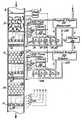
- The angle figure indicates schematically in elevation the arrangement of two control sections, preceded by a flowmeter and a static backmixer, and followed by a final sensor section, which constitutes one embodiment of this invention.
- In the Figure, an orifice flowmeter is designated by 1. However, any accurate flowmeter with electrical signal output may be used. In case the process line is an open ditch, a metering flume will be more appropriate. 2 designates a static mixer of the backmixing type, symbolized by a bed of "Raschig Rings". These rings are sections of thin-walled tubing, about as high as they are wide. Such a bed not only repeatedly splits and joins separate stream threads of the process liquid, but within the cavities of the rings some process liquid is retained and released at a slower rate than the average process flow rate, producing the effect of backmixing. The end result is that a step- change of composition in the process stream is stretched into a ramp-change of composition, radially homogeneous from pipe-wall to pipeline center, rather than with a parabolic front as in plug flow.
- A grid across the process line carrying a number of composition sensors, is designated by 3. These sensors have to operate reliably under total immersion under some ambient over-pressure. "Button Electrodes" of the type described in U.S. Patent No. 4,133,732, issued January 9, 1979, by the same inventor, embedded with some polymer in a rigid supporting grid, and preferably accompanied by an impedance transforming integrated circuit operating individually for each individual electrode, would be able to satisfactorily perform the demanding service required. The sensors should be positioned such that shear flow across their sensitive faceplate maximizes fast response.
- The grid supporting the sensors may be followed by or be made part of, the distribution system which dispenses reagent evenly over the cross-section of the process stream, as shown by 4. It is advantageous to create local turbulence in the process liquid at the dispensing orifices in order to speed up the adjustment reaction between reagent and process liquid. Further mixing is enhanced by the non-backmixing static mixer 5. Such a static mixer is symbolized by a bed of spheres which split up and recombine the process stream without retention or backmixing, hence without introduction of deadtime between the reagent dispenser and the next grid of sensors. Various types of effective non-backmixing static mixers are commercially available.
- The static mixer 5 should be followed by the final sensor assembly 6 unless the control section is duplicated as discussed below. The sensors in grid 6 may be positioned as shown in grid 3, or in any different way which enhances shear flow of process liquid across their sensitive faceplates, as is shown in 6 by the use of flow deflectors. The final sensor-supporting grid also carries a reference electrode 7, again preferably of the type described in U.S. Patent No. 4,133,732, issued January 9, 1979 consisting of an electrode embedded in gelled endpoint-composition process liquid. By locating this reference electrode at the end of the composition-adjustment sections, there is minimum possibility of contamination of the reference gel in the long run. This reference electrode designates the base potential from which the signal potential of each of the many sensor electrodes is measured.
- Between mixer 5 and sensor grid 6, another reagent dispensing
section containing elements 8, 9, and 10 which are identical to respective elements 3, 4 and 5 may be inserted to fine- tune process liquid composition adjustment. A third and fourth section dispensing a different type of reagent may be added also. This total assembly of control sections, final grid and end mixers, including another backmixing static mixer similar to 2, to follow final sensor grid 6 for even better mixing of the adjusted process stream if desired, forms the mechanical part of the controller located in the process line. - The electrical composition-related signals put out by the sensors are processed electronically in a way to be discussed further down, to one signal going to the reagent dispensing
control valves 11, 12, 13, ... 18, 19. This command signal is digital, and has the form of a binary number or "word". Such a number consists of the digits 1 and 0, wherein a 1 causes the solenoid of a specific on-off solenoid valve to be energized and the valve opened. The appearance of a 0 for that particular valve, de-energizes the solenoid and causes the valve to close. By installing as many valves as digits in the control command word, every digit in the word may command its own valve. If now the valves are placed parallel to each other between a reagent reservoir under constant overpressure and the process line, and if each adjacent valve counting from the valve controlled by the least significant bit, is provided with an orifice which allows twice as much reagent to flow through as its smaller neighbor, every more significant bit in the control word commands a reagent flow twice as large as the flow commanded by its adjacent less significant bit. The total flow of the control valve assembly now becomes directly related to the total numerical value of the control command word. For example: a word of 10 binary digits or bits commands a total flow of from 0 to 1024 arbitrary units of flow although the diameters of the orifices in the 10 control valves only increase from 1 to 32 arbitrary length units. The subdivision in 10, or any other desired number of valves makes possible a very fast and very reproducible reagent flow control responding to commands for minute increases or decreases as fast as for large changes. -
Differential pressure controller 20 causes a constant pressure differential in the reagent liquid fromreservoir 21 across the control valves to process line pressure at 22, e.g. by pressurizing the reagent reservoir with air. A flow of carrier liquid 23 insures rapid transportation of even small amounts of reagent to the dispensing orifices in the process line at 4. This carrier liquid may be water or process liquid from the process stream, moved by a separate pump. - The drawing shows addition of controlled amount of liquid reagent. In a similar way slurry or powdered solid reagents can be added to the carrier liquid by feeders with sequentially doubling capacities, controlled by a binary control word. If two cascaded control sections are used, as shown in the Figure, the second, downstream, section may be fed from a similar
control valve assembly 24, which now advantageously dispenses dilutedreagent 25 fromdilutor 26 in order to make possible a wider range of controlled reagent addition to the process stream. Again, the reservoir of diluted reagent should be pressurized to a constant pressure differential overcontrol valves 24, by differential pressure controller 27, just as was done with the previous control section. However, if the previous section dispensed solid reagent, suspended or dissolved in carrier liquid, the second control section may advantageously narrow the final control range of the adjusted process liquid composition by using liquid reagent. Or the second, or any identical additional, control section may control the addition of a different reagent to correct a different deficiency in the process liquid, as e.g. acidic versus alkaline reagent in correcting the pH of the process stream which may be above as well as (at some other time) below the desired pH. The electrical signal derived from the sensors in that section will decide whether the section's reagent addition will be activated, or whether the pH calls for addition of different reagent from another section. In this case, it is of particular advantage that the system of on-off control valves can shut off tight; something which should not be counted on with present-day control valves. Since leakage means extra chemicals to be neutralized, it represents waste. - In order to accomplish the desired control valve operation, the electrical signal of the sensor electrodes has to be processed. This means that the high electrode impedance has to be lowered by an impedance transformer; the electrical analog signal between sensor and reference digitized; and the antilogarithm of this digital signal computed (or first antilogged and then digitized) by an integrated circuit 28. This has to be done for each individual sensor separately, and only then should the processed electrode signals be averaged, since only in this way a truly arithmetic average of composition signals can be obtained.
- Sensor electrodes by their nature have an output which is the logarithm of actual ionic concentration in the liquid to be measured. Should different electrode outputs, representing locally different ionic concentrations, be averaged directly by connecting in parallel, an average of the logarithms of ionic concentration differences would be obtained which mathematically may be called a geometric average. However, the actual difference in ion concentrations should be averaged by algebraic addition of these concentrations (and then division by the number of sensors), an operation of which the logarithm cannot be taken. Hence not geometrical, but arithmetical averaging is required. This refinement becomes meaningful if unbuffered process liquids have to be neutralized. Small local differences in ionic (hydrogen ion-) concentration turn into large differences in logarithms of these concentrations as shown by large differences in sensor potential. The geometric average of these large potential differences would deviate quite markedly from the small differences in antilogarithm of these potentials, or small differences in actual ion concentration which should be averaged arithmetically. To derive most benefit from this correction, the sensors should be positioned in such a way over the cross-section of the process line, that each represents a stream of process liquid of about equal volume.
- The averaged digital antilog output of the sensors lends itself directly to subtraction of the number of ion equivalents of reagent introduced into the process stream to produce the desired endpoint concentration; this output can also be multiplied by a variable factor, like process flow rate from flowmeter 1 or buffer capacity of the process liquid, computed from the downstream sensor response to a certain addition of reagent. All these computational manipulations of the averaged sensor signal, and its process into a valve command word of the proper format, may be done inexpensively by microprocessor 29 for the first, and 30, for the second control section in the drawing. Modern electronic technology may allow combination of all operations done by separately presented
circuit units 28, 29 and 30, in one VLSI (very large scale integrated circuit). This electronic processing is done momentary; in combination with the fast acting control valves, an inexpensive and sophisticated control action can be effected sufficiently fast to produce locally, on-line, the same satisfactory control as is obtained today with voluminous mixing tanks and active mixers, in batchwise control.
Claims (20)
Applications Claiming Priority (2)
| Application Number | Priority Date | Filing Date | Title |
|---|---|---|---|
| US900908 | 1978-04-28 | ||
| US05/900,908 US4181951A (en) | 1978-04-28 | 1978-04-28 | In-line pH and pIon controller |
Publications (3)
| Publication Number | Publication Date |
|---|---|
| EP0018971A4 EP0018971A4 (en) | 1980-06-23 |
| EP0018971A1 EP0018971A1 (en) | 1980-11-26 |
| EP0018971B1 true EP0018971B1 (en) | 1983-04-27 |
Family
ID=25413284
Family Applications (1)
| Application Number | Title | Priority Date | Filing Date |
|---|---|---|---|
| EP79900433A Expired EP0018971B1 (en) | 1978-04-28 | 1979-12-04 | P-ion controller and control of ionic concentration in a flow-line |
Country Status (6)
| Country | Link |
|---|---|
| US (1) | US4181951A (en) |
| EP (1) | EP0018971B1 (en) |
| JP (1) | JPS633323B2 (en) |
| CA (1) | CA1116719A (en) |
| DE (1) | DE2965265D1 (en) |
| WO (1) | WO1979000998A1 (en) |
Families Citing this family (8)
| Publication number | Priority date | Publication date | Assignee | Title |
|---|---|---|---|---|
| US4762796A (en) * | 1981-10-05 | 1988-08-09 | Exxon Research And Engineering Company | pH control of a process stream |
| US4648043A (en) * | 1984-05-07 | 1987-03-03 | Betz Laboratories, Inc. | Computerized system for feeding chemicals into water treatment system |
| US4766550A (en) * | 1985-10-30 | 1988-08-23 | Westinghouse Electric Corp. | Automatic on-line chemistry monitoring system |
| GB8614530D0 (en) * | 1986-06-14 | 1986-07-23 | Clean Water Co Ltd | Liquid treatment process |
| US5073499A (en) * | 1988-04-15 | 1991-12-17 | Westinghouse Electric Corp. | Chemical diagnostic system |
| US5481260A (en) * | 1994-03-28 | 1996-01-02 | Nordson Corporation | Monitor for fluid dispensing system |
| US5696696A (en) * | 1994-10-11 | 1997-12-09 | Betzdearborn, Inc. | Apparatus and method for automatically achieving and maintaining congruent control in an industrial boiler |
| US5923571A (en) * | 1994-10-11 | 1999-07-13 | Betzdearborn, Inc. | Apparatus and method for automatic congruent control of multiple boilers sharing a common feedwater line and chemical feed point |
Family Cites Families (7)
| Publication number | Priority date | Publication date | Assignee | Title |
|---|---|---|---|---|
| US3072146A (en) * | 1959-09-24 | 1963-01-08 | Gizeski Terrence | Digital regulator valve |
| US3664951A (en) * | 1970-07-22 | 1972-05-23 | Pollution Engineering Internat | Apparatus and process to treat waste water for pollution control and industrial reuse |
| US3718556A (en) * | 1970-07-22 | 1973-02-27 | Magna Corp | Ionic ph control |
| US3791793A (en) * | 1972-01-31 | 1974-02-12 | Leeds & Northrup Co | Adaptive feed forward-feedback control of the concentration of a selected ion of a solution |
| IT995258B (en) * | 1972-10-12 | 1975-11-10 | Benckiser Gmbh Joh A | DEVICE FOR MEASURING THE POTENTIAL OF OXIRIDUCTION OF LIQUID MEDIA |
| US3856668A (en) * | 1973-05-30 | 1974-12-24 | R Shubert | Method for treatment of coal washery waters |
| JPS5920974B2 (en) * | 1976-12-28 | 1984-05-16 | 電気化学工業株式会社 | Flowing liquid PH automatic control device |
-
1978
- 1978-04-28 US US05/900,908 patent/US4181951A/en not_active Expired - Lifetime
-
1979
- 1979-04-16 JP JP54500716A patent/JPS633323B2/ja not_active Expired
- 1979-04-16 DE DE7979900433T patent/DE2965265D1/en not_active Expired
- 1979-04-16 WO PCT/US1979/000236 patent/WO1979000998A1/en unknown
- 1979-04-27 CA CA000326485A patent/CA1116719A/en not_active Expired
- 1979-12-04 EP EP79900433A patent/EP0018971B1/en not_active Expired
Also Published As
| Publication number | Publication date |
|---|---|
| EP0018971A1 (en) | 1980-11-26 |
| DE2965265D1 (en) | 1983-06-01 |
| WO1979000998A1 (en) | 1979-11-29 |
| EP0018971A4 (en) | 1980-06-23 |
| US4181951A (en) | 1980-01-01 |
| JPS55500241A (en) | 1980-04-24 |
| JPS633323B2 (en) | 1988-01-22 |
| CA1116719A (en) | 1982-01-19 |
Similar Documents
| Publication | Publication Date | Title |
|---|---|---|
| EP0018971B1 (en) | P-ion controller and control of ionic concentration in a flow-line | |
| US5246026A (en) | Fluid measuring, dilution and delivery system | |
| US6129104A (en) | Method for automotive dose control of liquid treatment chemicals | |
| Leconte et al. | Pattern of reaction diffusion fronts in laminar flows | |
| US4642222A (en) | Polymer feed system | |
| US3791793A (en) | Adaptive feed forward-feedback control of the concentration of a selected ion of a solution | |
| CN111579618B (en) | Biochemical oxygen demand online automatic detection system and method based on microbial fuel cell | |
| Benefield et al. | A kinetic model for the activated sludge process which considers diffusion and reaction in the microbial floc | |
| CN2689231Y (en) | Standard gas intelligent proportioning apparatus | |
| CN207596676U (en) | A kind of automatic medicament feeding system | |
| CN108607462B (en) | Liquid mixing device and liquid flow control method | |
| JPH0221875B2 (en) | ||
| JPS57149950A (en) | Method for determination of hydrogen peroxide | |
| Schulz et al. | The role of mixing in ozone dissolution systems | |
| CN217437844U (en) | Dosing system based on ammonia concentration analyzer | |
| JP2018025454A (en) | Hydrogen peroxide analyzer and hydrogen peroxide analysis method | |
| CN213041613U (en) | Water quality analyzer | |
| CN217288206U (en) | PH regulation and control device | |
| CN206440610U (en) | A kind of nonequilibrium kinetics reaction system absorbance online testing device | |
| US4875178A (en) | Method to control the discharge of effluent | |
| CN217786978U (en) | Device for measuring conductivity by variable-proportion dilution method | |
| CN219252432U (en) | Liquid injection equipment | |
| CN217139983U (en) | Device for automatically adjusting pH of liquid on line | |
| Fosu et al. | A Program in Visual Basic for Simulation and Control of Acidic Wastewater Neutralisation System | |
| CN218345260U (en) | Fenton process wastewater treatment equipment and system |
Legal Events
| Date | Code | Title | Description |
|---|---|---|---|
| PUAI | Public reference made under article 153(3) epc to a published international application that has entered the european phase |
Free format text: ORIGINAL CODE: 0009012 |
|
| 17P | Request for examination filed | ||
| AK | Designated contracting states |
Designated state(s): CH DE FR GB SE |
|
| GRAA | (expected) grant |
Free format text: ORIGINAL CODE: 0009210 |
|
| AK | Designated contracting states |
Designated state(s): CH DE FR GB SE |
|
| REF | Corresponds to: |
Ref document number: 2965265 Country of ref document: DE Date of ref document: 19830601 |
|
| ET | Fr: translation filed | ||
| PGFP | Annual fee paid to national office [announced via postgrant information from national office to epo] |
Ref country code: FR Payment date: 19840514 Year of fee payment: 6 |
|
| PGFP | Annual fee paid to national office [announced via postgrant information from national office to epo] |
Ref country code: CH Payment date: 19840516 Year of fee payment: 6 |
|
| PGFP | Annual fee paid to national office [announced via postgrant information from national office to epo] |
Ref country code: DE Payment date: 19840612 Year of fee payment: 6 |
|
| PGFP | Annual fee paid to national office [announced via postgrant information from national office to epo] |
Ref country code: SE Payment date: 19840630 Year of fee payment: 6 |
|
| PG25 | Lapsed in a contracting state [announced via postgrant information from national office to epo] |
Ref country code: GB Effective date: 19880416 |
|
| PG25 | Lapsed in a contracting state [announced via postgrant information from national office to epo] |
Ref country code: SE Effective date: 19880417 |
|
| PG25 | Lapsed in a contracting state [announced via postgrant information from national office to epo] |
Ref country code: CH Effective date: 19880430 |
|
| GBPC | Gb: european patent ceased through non-payment of renewal fee | ||
| PG25 | Lapsed in a contracting state [announced via postgrant information from national office to epo] |
Ref country code: FR Free format text: LAPSE BECAUSE OF NON-PAYMENT OF DUE FEES Effective date: 19881229 |
|
| REG | Reference to a national code |
Ref country code: CH Ref legal event code: PL |
|
| PG25 | Lapsed in a contracting state [announced via postgrant information from national office to epo] |
Ref country code: DE Effective date: 19890103 |
|
| REG | Reference to a national code |
Ref country code: FR Ref legal event code: ST |
|
| EUG | Se: european patent has lapsed |
Ref document number: 79900433.8 Effective date: 19890725 |
|
| PLBE | No opposition filed within time limit |
Free format text: ORIGINAL CODE: 0009261 |
|
| STAA | Information on the status of an ep patent application or granted ep patent |
Free format text: STATUS: NO OPPOSITION FILED WITHIN TIME LIMIT |