EP0018921A1 - Device for electric transmission by a system of separable and contactless connections - Google Patents
Device for electric transmission by a system of separable and contactless connections Download PDFInfo
- Publication number
- EP0018921A1 EP0018921A1 EP80400614A EP80400614A EP0018921A1 EP 0018921 A1 EP0018921 A1 EP 0018921A1 EP 80400614 A EP80400614 A EP 80400614A EP 80400614 A EP80400614 A EP 80400614A EP 0018921 A1 EP0018921 A1 EP 0018921A1
- Authority
- EP
- European Patent Office
- Prior art keywords
- wall
- turn
- clamp
- transformer
- disposed
- Prior art date
- Legal status (The legal status is an assumption and is not a legal conclusion. Google has not performed a legal analysis and makes no representation as to the accuracy of the status listed.)
- Granted
Links
Images

Classifications
-
- H—ELECTRICITY
- H02—GENERATION; CONVERSION OR DISTRIBUTION OF ELECTRIC POWER
- H02G—INSTALLATION OF ELECTRIC CABLES OR LINES, OR OF COMBINED OPTICAL AND ELECTRIC CABLES OR LINES
- H02G3/00—Installations of electric cables or lines or protective tubing therefor in or on buildings, equivalent structures or vehicles
- H02G3/22—Installations of cables or lines through walls, floors or ceilings, e.g. into buildings
-
- G—PHYSICS
- G01—MEASURING; TESTING
- G01R—MEASURING ELECTRIC VARIABLES; MEASURING MAGNETIC VARIABLES
- G01R15/00—Details of measuring arrangements of the types provided for in groups G01R17/00 - G01R29/00, G01R33/00 - G01R33/26 or G01R35/00
- G01R15/14—Adaptations providing voltage or current isolation, e.g. for high-voltage or high-current networks
- G01R15/18—Adaptations providing voltage or current isolation, e.g. for high-voltage or high-current networks using inductive devices, e.g. transformers
- G01R15/183—Adaptations providing voltage or current isolation, e.g. for high-voltage or high-current networks using inductive devices, e.g. transformers using transformers with a magnetic core
- G01R15/185—Adaptations providing voltage or current isolation, e.g. for high-voltage or high-current networks using inductive devices, e.g. transformers using transformers with a magnetic core with compensation or feedback windings or interacting coils, e.g. 0-flux sensors
-
- H—ELECTRICITY
- H01—ELECTRIC ELEMENTS
- H01F—MAGNETS; INDUCTANCES; TRANSFORMERS; SELECTION OF MATERIALS FOR THEIR MAGNETIC PROPERTIES
- H01F38/00—Adaptations of transformers or inductances for specific applications or functions
- H01F38/14—Inductive couplings
Definitions
- the invention relates to a method and a device for electrical transmission by a removable contactless connection system.
- connection systems In many applications, it is desirable to be able to have removable connection systems presenting no risk of establishing an electric current by manual contact. It is also desirable to be able to have connection systems whose connection does not give rise to the establishment of any electric arc, in particular when these systems are used in an explosion-proof environment or in mines.
- the subject of the present invention is a method and an electrical transmission device which does not have the drawbacks of prior devices, that is to say that it avoids any risk of establishment of an electric current when it is disconnected, and any risk of an electric arc appearing at the connector.
- it when it is used to handle dangerous products, it allows a perfectly sealed crossing of the cell walls, allows a remote connection of the devices contained in the cell particularly simple and includes parts crossing the wall not sensitive to corrosion.
- this device is particularly simple and reliable and, in several of its embodiments, it allows the disassembly of wearing parts without breaking the seal.
- an electrical transmission method carried out in accordance with the invention is characterized in that it consists in applying an electric current to the primary of a power transformer whose secondary consists of at least one turn, and to collect. an electrical current corresponding to the secondary of at least one distribution transformer, the primary of which is constituted by said turn, the secondary of the distribution transformer being disposed in a removable member constituting the moving part of the connection system.
- the electric current applied to the primary of the supply transformer comprises a power current to which a modulated circuit ensuring the transmission of coded information is superimposed.
- the supply and distribution transformers are preferably arranged on either side of a wall, the turn common to these transformers passing through this wall.
- the invention also relates to an electrical transmission device comprising a supply transformer and at least one distribution transformer, these transformers having a common winding constituted by at least one turn which defines the secondary of the supply transformer and the primary of the transformer. distribution, the secondary of the latter being disposed in a removable member.
- the removable member is a clamp comprising a handle capable of being grasped by a remote handling device.
- the removable member is a clamp which carries rollers capable of rolling on suitable cam surfaces to control the opening and closing of the clamp when the latter moves according to a determined direction.
- the rollers are then mounted at the ends of the jaws of the clamp, the cam surfaces being formed by the external surfaces of the turn or of a sheath surrounding the turn.
- the rollers are mounted on horns integral with the jaws of the removable clamp, the cam surfaces being formed on an attached member.
- the removable member is associated with a member movable in translation in a direction parallel to the axis of the turn and / or movable in rotation about this axis.
- a structure can in particular make it possible to control the movements of a carriage, a guillotine door or a door.
- the device when the device is intended to transmit a three-phase electric current, it comprises three turns making it possible to transmit the three phases of the electric currents.
- This particular structure makes it possible to transmit the electrical energy necessary for the implementation of a device supplied with three-phase current.
- the supply transformer is arranged on one side of the wall and the distribution transformer is arranged on the other side of the wall, the turn common to these transformers crossing the wall.
- the turn is then fixed to the wall in a sealed manner at the crossing points.
- This attachment can be achieved by welding the coil on the wall, and in particular on the stainless steel shielding which generally defines the internal face of the wall.
- the part of the turn disposed on the other side of the wall is received in a sheath fixed to the wall in a sealed manner.
- the sealed fixing is preferably carried out by welding the sheath to the wall, and in particular to the shield defining the internal face of the latter.
- the sheath thus constitutes a tubular projection of the wall connected to the latter by its two ends, so that the interior of said protuberance communicates with the first side of the wall, the coil common to the transformers being disposed on the first side of the wall and inside the tubular outgrowth.
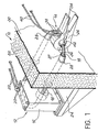
- FIG. 1 there is shown in exploded view a wall 10, such as one of the walls of a cell intended to receive dangerous products, for example explosive products.
- Various devices (not shown), intended for the manipulation of these products, for the detection of certain phenomena and for carrying out measurements of all kinds are also placed inside the cell. These devices can be for example jacks, carriages, doors, relays, as well as measuring and controlling devices of all kinds. They are usually controlled by electrical energy from outside the cell, and for measurement and control devices must transmit certain information to reading or recording systems located outside the cell. cell. Some of these devices must also receive control signals sent outside the cell.
- the transmission of different signals that are electrical operating power of the devices and the information provided in particular by the measurement and control apparatus through the wall 10 takes place by means of a device comprising a supply transformer 12 disposed outside the cell and a distribution transformer 14 disposed inside the cell.
- the transformers 12 and 14 can be either current transformers or voltage transformers depending on the operating point chosen on the characteristic in charge of the device.
- the primary winding and the core of the transformer 12 are arranged in a housing 16 and the secondary winding 18 of this transformer consists of a single turn, preferably made from a bar, a tube or even wires of twisted copper.
- the winding primary of transformer 12 is supplied by a current source (not shown) electrically connected to the outputs 20 of this winding via wires 22.
- the outputs 20 can be connected simultaneously to measurement, playback or recording (not shown).
- the housing 16 enclosing the primary winding and the core of the transformer 12 is carried by a support plate 24 which can be fixed to the wall 10 of the cell.
- the single turn 18 which constitutes the secondary winding of the transformer 12 passes through the wall 10 in a sealed manner so as to constitute the primary winding of the transformer 14.
- the secondary winding thus. that the core of the transformer 14 are arranged inside a removable member such as a clamp 26 intended to be mounted and dismounted remotely by means of a conventional manipulator.
- the clamp 26 is an amperometric clamp whose principle is well known in the art.
- the part of the copper coil 19 disposed inside the cell is received in a sheath 27 fixed in a sealed manner by welds 28 to the internal shielding 30 of the wall 10, the main part 32 of which consists of a layer of lead.
- the sheath 27 thus constitutes a tubular projection of the wall 10 in the cell.
- This structure makes it possible to obtain a perfect seal between the inside and the outside of the cell delimited by the wall 10.
- the sheath 27 constitutes a protuberance from the wall 10, and, more precisely, its internal shielding 30, inside the cell, of such that the turn 18 does not actually penetrate inside the cell although it crosses the wall 10 thereof. This characteristic, essential when the device according to the invention is intended.
- the sheath 27 and the internal shielding 30 of the wall 10 are made of stainless steel, which makes it possible to limit the losses due to the eddy currents.
- the coil 18 may optionally be covered with insulation.
- the copper coil 18 is tightly fixed to the wall 10 at the crossing points by welds 29 made directly between the coil 18 and the internal shielding 30, of the wall 10.
- This shield 30 constitutes a shunt for the turn 18.
- the resistivity of the shield is much greater than that of the turn, the shunt derives only a small part of the current.
- the clamp 26 includes a handle 34 whose shape is designed so that it can be grasped remotely by a manipulator and two jaws 36 in which are housed the secondary winding and the core of the transformer 14.
- the clamp 26 also comprises two sortias 38 by which the secondary winding of the transformer is electrically connected by means of wires 40 to at least one of the instruments arranged at the inside the cell.
- the turn 18 can be received with a relatively large clearance in the space 42, which facilitates the remote mounting of the clamp 26.
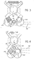
- rollers 44 are rotatably mounted on horns 46 integral with the jaws 36 of the clamp, the latter being biased in the closed position by a spring 48.
- a member 50 fixed to another wall 52 of the cell, defines two facing cam surfaces 54, symmetrical along a plane passing through the axis of the coil 18, on which the rollers roll 44 when the clamp moves perpendicular to the plane defined by the turn and contained in the plane of symmetry of the cam surfaces.
- the cam surfaces 54 are designed and arranged so that the clamp 26 opens when it passes at the level of the coil 18, then closes around it.
- the handle 34 of the clamp 26 comprises a dovetail 56 capable of being received in a corresponding groove formed at the end of a manipulator arm 58 shown in phantom.
- the handle 34 further comprises a guide piston 60 extending the arm 58, and designed to be: received in a cylinder 62 formed in the psroi 52, so as to guide the arm 58 in its displacement along a vertical axis in the variant shown , so that the rollers 44 remain vis-à-vis the cam surfaces 54.
- the rollers 44 are mounted directly on the jaws 36, so as to come into contact with the external surface of the sheath 27 before the end of the jaws.
- a spring 48 also urges the clamp in the closed position.
- the assembly and disassembly of the clamp is carried out as in the variant shown in Figure 2 by moving the clamp along an axis perpendicular to the plane of the coil 18 and passing through the axis thereof.
- the clamp is shown during assembly or disassembly in Figure 3, while the rollers 44 are in contact with the outer surface of the sheath, and in the operating position in Figure 4, the ends of the jaws 36 being in contact with each other.
- rollers are offset relative to each other so as to allow them to overlap.
- clamps 26 can be mounted on the same turn 18, for example by means of the cam surfaces formed on at least one second member 50 'identical to the member 50.
- the shape and orientation of the turn 18 can be adapted according to the envisaged application, so as to allow the movement of the clamps 26 relative to the turn 18.
- the coil 18 can be arranged in a horizontal plane and present inside the cell the shape of an arc of a circle, as illustrated in FIG. 1.
- Such an arrangement can allow, for example, feeding electric motor controlling the rotation of an arm or the operation of a door, the latter directly carrying the clamp (s) 26.
- the coil 18, still arranged in a horizontal plane, can also have inside the cell a straight part along which the clamp 26 can move, the latter being associated, for example, with a carriage capable of move on rails inside the enclosure.
- the carriage can carry a certain number of pliers of the type of pliers 26, the turn 18 then being held regularly by supports and mechanisms automatically controlling the opening of the pliers when they pass vis-à-vis these supports.
- the turn is rectangular and arranged in a substantially vertical plane, which allows for example the clamp 26 to be associated with a quillotine door, the electric motor controlling the implementation of which is supplied by means of a device according to the invention.
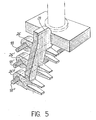
- the device according to the invention is used to transmit a three-phase electric current, intended for the supply of a three-phase device.
- the transformers 12 and 14 are three-phase transformers, which implies that the device comprises three turns 18, 18 'and 18 ", preferably of the same shape, parallel and arranged at equal distance from each other.
- these turns pass through the wall 10 in the same way as the single turn in the embodiment described above.
- These turns receive one or more clamps 26, 26 ′, 26 "whose jaws define three spaces intended to each receive one of the turns.
- the turn 18 and the clamp 26 which have just been fixed on this part therefore play the same role as a socket in known devices.
- no current When the coil 18 is touched, no electrical contact is established, so that any risk of accident is avoided.
- opening and closing of the clamp 26 does not give rise to the elimination and establishment of an electrical contact, so that no electric arc can be created.
- the closing of the clamp is only accompanied by the closing of a magnetic flux in the core disposed inside the clamp.
- the device according to the invention allows remote handling much easier than conventional power outlets. Finally, it allows easy replacement of all wearing parts.
- the wires 22 are connected to a current source (not shown) supplying the primary winding of the transformer 12. Under the effect of the supply current, and via the transformers 12 and 14, an electric current s' established in the circuit comprising the device or devices (s) connected to the wires 40 and the secondary winding of the transformer 14.
- the various devices placed behind the wall 10 are thus energized.
- the yield of such a device can reach approximately 0.5 when the length of the coil 18 is not too great and when the clearance between this turn and the cores of transformers 12 and 14 remains limited.
- a power of around 1KW can then be transmitted to a device located inside the cell delimited by the partition 10.
- the device according to the invention provides double galvanic isolation between the current source connected to terminals 20 and the device to be supplied connected to terminals 38.
- the device according to the invention makes it possible to supply one or more apparatuses placed inside the enclosure, it also makes it possible to transmit through the wall 10, in one or the other direction, coded orders and information.
- the transmission of orders and information takes place by modulated current, in the form of discrete frequencies or frequency variations superimposed on the supply current.
- This coded information can be, for example, measurement results, or else control commands or signaling information.
- the transmitted frequency can reach approximately 10 kHz, and the bandwidth of the device according to the invention is very wide.
- the separation of the coded information and the supply current can then be carried out in a known manner using synchronous filters or detectors before the coded information is transmitted to direct reading devices or to recorders.
- the coil 18 when it is welded to the wall as illustrated in FIG. 2, and the sheath 27 when the coil is received in a sheath welded to the wall, as illustrated Figure 1, are not removable. So all the other parts of the device, and in particular the parts arranged inside the cell, can be changed without requiring any particular disassembly when they are worn or damaged, for example when a particularly corrosive atmosphere prevails inside the enclosure .
- the device according to the invention is therefore particularly safe and reliable and is also distinguished for this reason from the known devices making it possible to transmit electrical signals.
- the device according to the invention can be used in all cases where an electrical outlet is necessary, in order to avoid any risk of accident or explosion.
- the shape and orientation of the turn can be modified depending on the intended application.
- the clamp 26 can be replaced by another removable member and its shape, and in particular that of the handle 34 and the jaws 36, can be modified, in particular when this clamp must be manipulated from a distance.
- the device according to the invention can be used as soon as electrical signals must be transmitted and whatever the nature of the products handled near the device and the nature of the ambient environment.
- the latter can be both a gas and a liquid
- the device according to the invention can be used in an underwater or aquatic environment.
Abstract
On applique un courant électrique au primaire d'un transformateur d'alimentation (12) dont le secondaire (18) est constitué par au moins une spire, et on recueille un courant électrique correspondant au secondaire d'un transformateur de distribution (14) dont le primaire est constitué par ladite spire, le secondaire du transformateur de distribution étant disposé dans un organe amovible, tel qu'une pince (26), constituant le pièce mobile du système de connexion. Application à la transmission et à la distribution d'un courant électrique, par exemple au travers d'une paroi (10).An electrical current is applied to the primary of a supply transformer (12) whose secondary (18) is constituted by at least one turn, and an electrical current corresponding to the secondary of a distribution transformer (14) is collected. the primary consists of said turn, the secondary of the distribution transformer being disposed in a removable member, such as a clamp (26), constituting the moving part of the connection system. Application to the transmission and distribution of an electric current, for example through a wall (10).
Description
L'invention concerne un procédé et un dispositif de transmission électrique par un système de connexion amovible sans contact.The invention relates to a method and a device for electrical transmission by a removable contactless connection system.
Dans de nombreuses applications, il est souhaitable de pouvoir disposer de systèmes de raccordement amovibles ne présentant aucun risque d'établissement d'un courant électrique par contact manuel. Il est également souhaitable de pouvoir disposer de systèmes de raccordement dont le branchement ne donne lieu à l'établissement d'aucun arc électrique, notamment lorsque ces systèmes sont utilisés en milieu déflagrant ou dans les mines.In many applications, it is desirable to be able to have removable connection systems presenting no risk of establishing an electric current by manual contact. It is also desirable to be able to have connection systems whose connection does not give rise to the establishment of any electric arc, in particular when these systems are used in an explosion-proof environment or in mines.
En outre, dans certaines applications particulières, et notamment lorsqu'on est en présence de produits dangereux, ces produits doivent être disposés à l'intérieur d'une cellule étanche ou derrière une paroi étanche et manipulés à distance au travers des parois. Au cours de ces différentes manipulations, un certain nombre de dispositifs et d'appareillages qui se trouvent derrière la paroi ou à l'intérieur de la cellule sont commandés électriquement, et les résultats de mesures effectuées sur ces produits doivent être communiqués à des appareils de lecture ou d'enregistrement situés à l'extérieur. La transmission de l'énergie électrique disponible à l'extérieur de la cellule vers des appareils situés à l'intérieur de celle-ci, ainsi que la communication vers l'extérieur de la cellule d'informations telles que les résultats de mesures effectuées à l'intérieur posent différents problèmes. Il s'agit tout d'abord de problèmes d'étanchéité au niveau de la traversée des parois par les fils ou les câbles électriques généralement utilisés. Il s'agit également de problèmes posés par le branchement à distance des appareils utilisés à l'intérieur de la cellule sur des prises de courant classiques au moyen de manipulateurs. Il s'agit enfin de problèmes posés par la corrosion des parties de câbles ou de fils et des prises de courant situées à l'intérieur de la cellule lorsque les produits manipulés sont particulièrement agressifs.In addition, in certain particular applications, and in particular when dangerous products are present, these products must be placed inside a sealed cell or behind a sealed wall and manipulated remotely through the walls. During these various manipulations, a certain number of devices and apparatuses which are behind the wall or inside the cell are electrically controlled, and the results of measurements carried out on these products must be communicated to apparatuses of reading or recording located outside. The transmission of the electrical energy available outside the cell to devices located inside it, as well as the communication to the outside of the cell of information such as the results of measurements carried out at the interior poses different problems. First of all, there are sealing problems at the level of the generally used electric wires or cables. These are also problems posed by the remote connection of the devices used inside the cell to conventional electrical outlets by means of manipulators. Finally, these are problems posed by corrosion of the parts of cables or wires and of the sockets situated inside the cell when the products handled are particularly aggressive.
La présente invention a pour objet un procédé et un dispositif de transmission électrique ne présentant pas les inconvénients des dispositifs antérieurs, c'est-à-dire qu'il évite tout risque d'établissement d'un courant électrique lorsqu'il est débranché, et tout risque d'apparition d'un arc électrique au niveau du connecteur. En outre, lorsqu'il est utilisé pour manipuler-des produits dangereux, il permet une traversée parfaitement étanche des parois de la cellule, autorise un branchement à distance des appareils contenus dans la cellule particulièrement simple et comprend des parties traversant la paroi non sensibles à la corrosion. Enfin, ce dispositif est particulièrement simple et fiable et, dans plusieurs de ses réalisations, il permet le démontage des pièces d'usure sans rupture de l'étanchéité.The subject of the present invention is a method and an electrical transmission device which does not have the drawbacks of prior devices, that is to say that it avoids any risk of establishment of an electric current when it is disconnected, and any risk of an electric arc appearing at the connector. In addition, when it is used to handle dangerous products, it allows a perfectly sealed crossing of the cell walls, allows a remote connection of the devices contained in the cell particularly simple and includes parts crossing the wall not sensitive to corrosion. Finally, this device is particularly simple and reliable and, in several of its embodiments, it allows the disassembly of wearing parts without breaking the seal.
Dans ce but, un procédé de transmission électrique réalisé conformément à l'invention se caractérise en ce qu'il consiste à appliquer un courant électrique au primaire d'un transformateur d'alimentation dont le secondaire est constitué par au moins une spire, et à recueillir. un cournnt électrique correspondant au secondaire d'au moins un transformateur de distribution dont le primaire est constitué par ladite spire, le secondaire du transformateur de distribution étant disposé dans un organe amovible constituant la pièce mobile du système de connexion.To this end, an electrical transmission method carried out in accordance with the invention is characterized in that it consists in applying an electric current to the primary of a power transformer whose secondary consists of at least one turn, and to collect. an electrical current corresponding to the secondary of at least one distribution transformer, the primary of which is constituted by said turn, the secondary of the distribution transformer being disposed in a removable member constituting the moving part of the connection system.
Dans un mode de réalisation particulier de l'invention, le courant électrique appliqué au primaire du transformateur d'alimentation comprend un courant de puissance auquel est superposé un cournnt modulé assurant la transmission d'informations codées.In a particular embodiment of the invention, the electric current applied to the primary of the supply transformer comprises a power current to which a modulated circuit ensuring the transmission of coded information is superimposed.
Les transformateurs d'alimentation et de distribution sont disposés de préférence de part et d'autre d'une paroi, la spire commune à ces transformateurs traversant cette paroi.The supply and distribution transformers are preferably arranged on either side of a wall, the turn common to these transformers passing through this wall.
L'invention concerne également un dispositif de transmission électrique comprenant un transformateur d'alimentation et au moins un transformateur de distribution, ces transformateurs ayant un enroulement commun constitué par au moins une spire qui définit le secondaire du transformateur d'alimentation et le primaire du transformateur de distribution, le secondaire de ce dernier étant disposé dans un organe amovible.The invention also relates to an electrical transmission device comprising a supply transformer and at least one distribution transformer, these transformers having a common winding constituted by at least one turn which defines the secondary of the supply transformer and the primary of the transformer. distribution, the secondary of the latter being disposed in a removable member.
Conformément à une autre caractéristique de l'invention, l'organe amovible est une pince comprenant une poignée susceptible d'être saisie par un appareil de manipulation à distance.According to another characteristic of the invention, the removable member is a clamp comprising a handle capable of being grasped by a remote handling device.
Conformément à encore une autre caractéristique de l'invention, l'organe amovible est une pince qui porte des galets susceptibles de rouler sur des surfaces de came appropriées pour commander l'ouverture et la fermeture de la pince lorsque celle-ci se déplace selon une direction déterminée. Selon une première variante, les galets sont alors montés aux extrémités des mors de la pince, les surfaces de came étant constituées par les surfaces externes de la spire ou d'une gaine entourant la spire. Selon une deuxième variante, les galets sont montés sur des guignols solidaires des mors de la pince amovible, les surfaces de came étant formées sur un organe rapporté.According to yet another characteristic of the invention, the removable member is a clamp which carries rollers capable of rolling on suitable cam surfaces to control the opening and closing of the clamp when the latter moves according to a determined direction. According to a first variant, the rollers are then mounted at the ends of the jaws of the clamp, the cam surfaces being formed by the external surfaces of the turn or of a sheath surrounding the turn. According to a second variant, the rollers are mounted on horns integral with the jaws of the removable clamp, the cam surfaces being formed on an attached member.
Selon une autre caractéristique de l'invention, l'organe amovible est associé à un organe mobile en translation dans une direction parallèle à l'axe de la spire et/ou mobile en rotation autour de cet axe. Une telle structure peut permettre notamment de commander les déplacements d'un chariot, d'une porte guillotine ou d'une porte.According to another characteristic of the invention tion, the removable member is associated with a member movable in translation in a direction parallel to the axis of the turn and / or movable in rotation about this axis. Such a structure can in particular make it possible to control the movements of a carriage, a guillotine door or a door.
Selon encore une autre caractéristique de l'invention, lorsque le dispositif est destiné à transmettre un courant électrique triphasé, il comprend trois spires permettant de transmettre les trois phases des courants électriques. Cette structure particulière permet de transmettre l'énergie électrique nécessaire à la mise en oeuvre d'un appareil alimenté en courant triphasé.According to yet another characteristic of the invention, when the device is intended to transmit a three-phase electric current, it comprises three turns making it possible to transmit the three phases of the electric currents. This particular structure makes it possible to transmit the electrical energy necessary for the implementation of a device supplied with three-phase current.
Lorsque le dispositif selon l'invention est destiné à transmettre un courant électrique au travers d'une paroi, le transformateur d'alimentation est disposé d'un premier côté de la paroi et le transformateur de distribution est disposé de l'autre côté de la paroi, la spire commune à ces transformateurs traversant la paroi.When the device according to the invention is intended to transmit an electric current through a wall, the supply transformer is arranged on one side of the wall and the distribution transformer is arranged on the other side of the wall, the turn common to these transformers crossing the wall.
Selon une première variante, la spire est alors fixée à la paroi de façon étanche aux points de traversée. Cette fixation peut être réalisée par soudure de la spire sur la paroi, et notamment sur le blindage en acier inoxydable qui définit généralement la face interne de la paroi.According to a first variant, the turn is then fixed to the wall in a sealed manner at the crossing points. This attachment can be achieved by welding the coil on the wall, and in particular on the stainless steel shielding which generally defines the internal face of the wall.
Selon une deuxième variante, la partie de la spire disposée de l'autre côté de la paroi est reçue dans une gaine fixée àLla paroi de façon étanche. Comme dans la première variante, la fixation étanche est réalisée de préférence par soudure de la gaine sur la paroi, et notamment sur le blindage définissant la face interne de celle-ci. La gaine constitue ainsi une excroissance tubulaire de la paroi reliée à celle-ci par ses deux extrémités, de telle sorte que l'intérieur de ladite excroissance communique avec le premier côté de la paroi, la spire commune aux transformateurs étant disposée du premier côté de la paroi et à l'intérieur de l'excroissance tubulaire.According to a second variant, the part of the turn disposed on the other side of the wall is received in a sheath fixed to the wall in a sealed manner. As in the first variant, the sealed fixing is preferably carried out by welding the sheath to the wall, and in particular to the shield defining the internal face of the latter. The sheath thus constitutes a tubular projection of the wall connected to the latter by its two ends, so that the interior of said protuberance communicates with the first side of the wall, the coil common to the transformers being disposed on the first side of the wall and inside the tubular outgrowth.
On décrira maintenant, à titre d'exemple non limitatif, un mode de réalisation particulier de l'invention en se référant aux dessins annexés dans lesquels :
- - la figure 1 est une vue en perspective d'un dispositif de transmission de courants électriques au travers d'une paroi.étanche,
- - la figure 2 est une vue en perspective représentant une variante de réalisation du dispositif de la figure 1, et notamment de la pince dans laquelle est logé le-secondaire du transformateur de distribution,
- - les figures 3 et 4 représentent une autre variante de la pince, respectivement en cours de montage et après montage, et
- - la figure 5 est une vue en perspective illustrant une application du dispositif selon l'invention à la transmission d'un courant triphasé.
- FIG. 1 is a perspective view of a device for transmitting electric currents through a wall.
- FIG. 2 is a perspective view showing an alternative embodiment of the device of FIG. 1, and in particular of the clamp in which the secondary of the distribution transformer is housed,
- FIGS. 3 and 4 show another variant of the clamp, respectively during assembly and after assembly, and
- - Figure 5 is a perspective view illustrating an application of the device according to the invention to the transmission of a three-phase current.
Sur la figure 1, on a représenté en vue éclatée une paroi 10, telle que l'une des parois d'une cellule destinée à recevoir des produits dangereux, par exemple des produits explosifs. Différents appareils (non représentés), destinés à la manipulation de ces produits, à la détection de certains phénomènes et à la réalisation de mesures de toutes sortes sont également disposés à l'intérieur de la cellule. Ces appareils peuvent être par exemple des vérins, des chariots, des portes, des relais, ainsi que des appareils de mesure et de contrôle de toutes sortes. Ils sont généralement commandés au moyen d'une énergie électrique provenant de l'extérieur de la cellule, et pour les appareils de mesure et de contrôle, doivent transmettre certaines informations à des systèmes de lecture ou d'enregistrement situés à l'extérieur de la cellule. Certains de ces appareils doivent également recevoir des signaux de commande émis à l'extérieur de la cellule. En outre, en raison de l'atmosphère régnant à l'intérieur de la cellule, il n'est pas possible de pénétrer à l'intérieur de celle-ci, de telle sorte que toutes les manipulations doivent être effectuées à distance, par exemple au moyen de manipulateurs traversant également les parois de la cellule. En particulier, les branchements électriques des différents appareils disposés à l'intérieur de la cellule sont effectués à distance de cette façon.In Figure 1, there is shown in exploded view a
'Conformément à l'invention, la transmission des différents signaux électriques que constituent l'énergie d'alimentation des appareils et les informations fournies notamment par les appareils de mesure et de contrôle au travers de la paroi 10 s'effectue au moyen d'un dispositif comprenant un transformateur d'alimentation 12 disposé à l'extérieur de la cellule et untransformateur de distribution 14 disposé à l'intérieur de la cellule. Les transformateurs 12 et 14 peuvent être soit des transformateurs de courant, soit des transformateurs de tension selon le point de fonctionnement choisi sur la caractéristique en charge du dispositif. L'enroulement primaire et le noyau du transformateur 12 sont disposés dans un boîtier 16 et l'enroulement secondaire 18 de ce transformateur est constitué par une spire unique, réalisée de préférence à partir d'une barre, d'un tube ou encore de fils de cuivre torsadés. L'enroulement primaire du transformateur 12 est alimenté par une source de courant (non représentée) reliée électriquement aux sorties 20 de cet enroulement par l'intermédiaire de fils 22. Comme on le verra par la suite, les sorties 20 peuvent être reliées simultanément à des appareils de mesure, de lecture ou d'enregistrement (non représentés). Le boîtier 16 enfermant l'enroulement primaire et le noyau du transformateur 12 est porté par un plateau support 24 qui peut être fixé à la paroi 10 de la cellule. In accordance with the invention, the transmission of different signals that are electrical operating power of the devices and the information provided in particular by the measurement and control apparatus through the
Conformément à l'invention, la spire unique 18 qui constitue l'enroulement secondaire du transformateur 12 traverse de façon étanche la paroi 10 de façon à constituer l'enroulement primaire du transformateur 14. L'enroulement secondaire ainsi. que le noyau du transformateur 14 sont disposés à l'intérieur d'un organe amovible tel qu'une pince 26 prévue pour être montée et démontée à distance au moyen d'un manipulateur classique. La pince 26 est une pince ampéremétrique dont le principe est bien connu dans la technique.According to the invention, the
Dans le mode de réalisation représenté sur la figure 1, la partie de la spire de cuivre 19 disposée à l'intérieur de la cellule est reçue dans une gaine 27 fixée de façon étanche par des soudures 28 au blindage interne 30 de la paroi 10, dont la partie principale 32 est constituée par une couche de plomb. La gaine 27-constitue ainsi une excroissance tubulaire de la paroi 10 dans la cellule. Cette structure permet d'obtenir une étanchéité parfaite entre l'intérieur et l'extérieur de la cellule délimitée par la paroi 10. De plus, et comme l'illustre clairement la figure 1, la gaine 27 constitue une excroissance de la paroi 10, et, plus précisément, de son blindage interne 30, à l'intérieur de la cellule, de telle sorte que la spire 18 ne pénètre pas réellement à l'intérieur de la cellule bien qu'elle traverse la paroi 10 de celle-ci. Cette caractéristique, essentielle lorsque le dispositif selon l'invention est destiné. à transmettre un courant électrique au travers de la paroi d'une cellule dans laquelle sont manipulés des produits dangereux, permet de transmettre ce courant sans que la paroi ne présente aucune discontinuité. Ceci permet notamment de n'utiliser aucun joint ou autre pièce d'usure non démontable au niveau de la traversée de la paroi par la spire. Il en résulte que toutes les pièces d'usure du système de connexion et aussi la spiré 18, peuvent être facilement démontées sans rupture de l'étanchéité de la cellule.In the embodiment shown in FIG. 1, the part of the copper coil 19 disposed inside the cell is received in a
De préférence, la gaine 27 et le blindage interne 30 de la paroi 10 sont réalisés en acier inoxydable, ce qui permet de limiter les pertes dues aux courants de Foucault. En outre, la spire 18 peut éventuellement être recouverte d'isolant.Preferably, the
Dans un autre mode de réalisation, représenté sur la figure 2, la spire de cuivre 18 est fixée de façon étanche à la paroi 10 aux points de traversée per des soudures 29 réalisées directement entre la spire 18 et le blindage interne 30, de la paroi 10. Comme dans le mode de réalisation précédent, l'étanchéité entre l'intérieur et l'extérieur de la cellule est ainsi parfaitement assurée. Ce blindage 30 constitue un shunt pour la spire 18.Cependant, étant donné que la résistivité du blindage est beaucoup plus grande que celle de la spire, le shunt ne dérive qu'une petite partie du courant.In another embodiment, shown in FIG. 2, the
La pince 26 comprend une poignée 34 dont la forme est conçue de f.içon à pouvoir être saisie à distance par un manipulateur et deux mors 36 dans lesquels sont logés l'enroulement secondaire et le noyau du transformateur 14. La pince 26 comprend également deux sortias 38 par lesquelles l'enroulement secondaire du transformateur est relié électriquement au moyen de fils 40 à au moins l'un des instruments disposés à l'intérieur de la cellule. Lorsque la pince 26 est fermée comme le montre la figure 1, les extrémités des mors 36 se touchent et le flux magnétique généré dans le noyau du transformateur 14 est fermé lorsque la spire 18 se trouve située dans un espace annulaire 42 défini entre les mors 36.The
Comme le montre la-figure 1, la spire 18 peut être reçue avec un jeu relativement important dans l'espace 42, ce qui facilite le montage à distance de la pince 26. Afin de faciliter encore le montage et le démontage de la pince, dans une variante de réalisation de la pince 26 représentée sur la figure 2, des galets 44 sont montés tournants sur des guignols 46 solidaires des mors 36 de la pince, celle-ci étant sollicitée en position fermée par un ressort 48. En outre, un organe 50, fixé à une autre paroi 52 de la cellule, définit deux surfaces de came en vis-à-vis 54, symétriques selon un plan passant par l'axe de la spire 18, sur lesquels viennent rouler les galets 44 lorsque la pince se déplace perpendiculaire au plan défini par la spire et contenu dans le plan de symétrie des surfaces de came. Les surfaces de came 54 sont conçues et disposées de telles sorte que la pince 26 s'ouvre lorsqu'elle passe au niveau de la spire 18, puis se referme autour de celle-ci.As shown in FIG. 1, the
Dans la variante de réalisation représentée sur la figure 2, la poignée 34 de la pince 26 comprend une queue d'aronde 56 susceptible d'être reçue dans une rainure correspondante formée à l'extrémité d'un bras de manipulateur 58 représenté en traits mixtes. La poignée 34 comprend de plus un piston de guidage 60 prolongeant le bras 58, et prévu pour être: reçu dans un cylindre 62 ménagé dans la psroi 52, de façon à guider le bras 58 dans son déplacement selon un axe vertical dans la variante représentée, afin que les galets 44 restent en vis-à-vis des surfaces de came 54.In the alternative embodiment shown in FIG. 2, the
Dans une autre variante de réalisation de l'invention représentée sur les figures 3 et 4, les galets 44 sont montés directement sur les mors 36, de façon à venir en contact avec la surface externe de la gaine 27 avant l'extrémité des mors. Un ressort 48 sollicite également la pince en position de fermeture. Le montage et le démontage de la pince s'effectuent comme dans la variante représentée sur la figure 2 en déplaçant la pince selon un axe perpendiculaire au plan de la spire 18 et passant par l'axe de celle-ci. La pince est représentée en cours de montage ou de démontage sur la figure 3, alors que les galets 44 sont en contact avec la surface externe de la gaine, et en position de fonctionnement sur la figure 4, les extrémités des mors 36 étant en contact l'une avec l'autre.In another alternative embodiment of the invention shown in Figures 3 and 4, the
On remarque que les galets sont décalés l'un par rapport à l'autre de façon à permettre leur chevauchement.Note that the rollers are offset relative to each other so as to allow them to overlap.
Dans les deux variantes de réalisation qui viennent d'être décrites en se référant aux figures 2 et 3, 4, la coopération des galets 44 avec les surfaces de came 54 ou avec les surfaces de came que définit la surface externe de la gaine 27 permet de réaliser le montage et le démontage à distance de la pince, par exemple au moyen d'un manipulateur, sans endommager les extrémités des mors 36 de la pince.In the two variant embodiments which have just been described with reference to FIGS. 2 and 3, 4, the cooperation of the
Par ailleurs, et comme illustré en traits mixtes sur la figure 2, plusieurs pinces 26 peuvent être montées sur une même spire 18, par exemple au moyen des surfaces de came formées sur au moins un second organe 50' identique à l'organe 50.Furthermore, and as illustrated in dashed lines in FIG. 2,
En outre, la forme et l'orientation de la spire 18 peuvent être adaptées en fonction de l'application envisagée, de façon à permettre le déplacement des pinces 26 par rapport à la spire 18.In addition, the shape and orientation of the
Ainsi, la spire 18 peut être disposée dans un plan horizontal et présenter à l'intérieur de la cellule la forme d'un arc de cercle, comme l'illustre la figure 1. Une telle disposition peut permettre, par exemple, l'alimentation électrique d'un moteur commandant la rotation d'un bras ou la manoeuvre d'une porte, ces derniers portant directement la ou les pinces 26.Thus, the
La spire 18, toujours disposée dans un plan horizontal, peut également présenter à l'intérieur de la cellule une partie rectiligne le long de laquelle peut se déplacer la pince 26, celle-ci étant associée, par exemple, à un chariot susceptible de se déplacer sur des rails à l'intérieur de l'enceinte. Lorsque le déplacement du chariot est important, il peut porter un certain nombre de pinces du type de la pince 26, la spire 18 étant alors maintenue régulièrement par des supports et des mécanismes commandant automatiquement l'ouverture des pinces lorsqu'elles passent en vis-à-vis de ces supports.The
Dans un autre mode de réalisation ( non représenté) la spire est rectangulaire et disposée dans un plan sensiblement vertical, ce qui permet par exemple à la pince 26 d'être associée à une porte quillotine dont le moteur électrique commandant la mise en oeuvre est alimenté par l'intermédiaire d'un dispositif selon l'invention.In another embodiment (not shown) the turn is rectangular and arranged in a substantially vertical plane, which allows for example the
Bien entendu, un grand nombre d'autres applications peuvent être envisagées et la forme et l'orientation de la spire 18 peuvent être modifiées en fonction de la direction de déplacement en translation et/ou en rotation du dispositif associé à la, ou aux pince (s) 26 et dont la mise en oeuvre est commandée-au moyen d'un système électrique alimenté en énergie électrique par le dispositif selon l'invention.Of course, a large number of other applications can be envisaged and the shape and orientation of the
Enfin, dans un autre mode de réalisation représenté sur la figure 5, le dispositif selon l'invention est utilisé pour transmettre un courant électrique triphasé, destiné à l'alimentation d'un appareil triphasé. Dans ce cas, les transformateurs 12 et 14 sont des transformateurs triphasés, ce qui implique que le dispositif comprend trois spires 18, 18' et 18", de préférence de même forme, parallèles et disposées à égale distance les unes des autres. Lorsque l'appareil à alimenter est disposé à l'intérieur d'une cellule, ces spires traversent la paroi 10 de la même façon que la spire unique dans le mode de réalisation décrit précédemment. Ces spires reçoivent une ou plusieurs pinces 26, 26', 26" dont les mors définissent trois espaces destinés à recevoir chacun l'une des spires. Les pinces 26, 26' et 26" sont fixées par un support commun 31 à un dispositif commandé par un courant triphasé, tel qu'un chariot (non représenté).Finally, in another embodiment shown in FIG. 5, the device according to the invention is used to transmit a three-phase electric current, intended for the supply of a three-phase device. In this case, the
Conformément à l'invention, la spire 18 et la pince 26 que l'on vient fixer sur cette partie jouent donc le même rôle qu'une prise de courant dans les dispositifs connus. En outre, aucun courant électrique ne s'établit lorsqu'on touche la spire 18, de sorte que tout risque d'accident est évité. De plus, l'ouverture et la fermeture de la pince 26 ne donnent pas lieu à la suppression et à létablis- semant d'un contact électrique, de telle sorte qu'aucun arc électrique ne peut se créer. Ceci permet d'utiliser le dispositif en milieu déflagrant ou dans les mines. En effet, la fermeture de la pince s'accompagne seulement de la fermeture d'un flux magnétique dans le noyau disposé à l'intérieur de la pince. De plus, le dispositif selon l'invention permet une manipulation à distance beaucoup plus facile que les prises de courant classiques. Enfin, il permet un remplacement aisé de toutes les pièces d'usure.In accordance with the invention, the
Le dispositif qui vient d'être décrit en se référant aux figures 1 à 5 fonctionne de la façon suivante.The device which has just been described with reference to Figures 1 to 5 operates as follows.
Afin de transmettre à l'intérieur de la cellule délimitée par la paroi 10 la puissance électrique nécessaire à la mise en oeuvre d'un ou de plusieurs appareils alimentés par les fils 40 branchés aux bornes 38 de l'enroulement secondaire logé dans la pince 26, les fils 22 sont raccordés à une source de courant (_non représentée) alimentant l'enroulement primaire du transformateur 12. Sous l'effet du courant d'alimentation, et par l'intermédiaire des transformateurs 12 et 14, un courant électrique s'établit dans le circuit comprenant le ou les appareils (s) connecté(s) aux fils 40 et l'enroulement secondaire du transformateur 14. Les différents appareils disposés derrière la paroi 10 sont ainsi mis sous tension. A titre indicatif, le rendement d'un tel dispositif peut atteindre environ 0,5 lorsque la longueur de la spire 18 n'est pas trop importante et lorsque le jeu entre cette spire et les noyaux des transformateurs 12 et 14 reste limité. Ure puissance d'environ 1KW peut alors être transmise à un appareil situé à l'intérieur de la cellule délimitée par la cloison 10.In order to transmit inside the cell delimited by the
On remarquera que le dispositif selon l'invention assure un double isolement galvanique entre la source de courant connectée aux bornes 20 et l'appareil à alimenter raccordé aux bornes 38.It will be noted that the device according to the invention provides double galvanic isolation between the current source connected to
De même que le dispositif selon l'invention permet d'alimenter un ou olusieurs appareils disposés à l'intérieur de l'enceinte, il permet également de transmettre au travers de la paroi 10, dans l'un ou l'autre sens, des ordres et des informations codés. La transmission des ordres et des informations s'effectue par courant modulé, sous forme de fréquences discrètes ou de variations de fréquences superposées au courant d'alimentation. Ces informations codées peuvent être, par exemple, des résultats de mesure, ou encore des ordres de commande ou des informations de signalisations. La fréquence transmise peut atteindre environ 10kHz, et la bande passante du dispositif selon l'invention est très large. La séparation des informations codées et du courant d'alimentation peut ensuite être effectuée de façon connue à l'aide de filtres ou de détecteurs synchrones avant que les informations codées ne soient transmises à des appareils de lecture directe-ou à des enregistreurs.Just as the device according to the invention makes it possible to supply one or more apparatuses placed inside the enclosure, it also makes it possible to transmit through the
Conformément à l'invention, on remarquera que seules la spire 18 lorsqu'elle est soudée à la paroi comme l'illustra la figure 2, et la gaine 27 lorsque la spire est reçue dans une gaine soudée à la paroi, comme l'illustre la figure 1, ne sont pas démontables. Ainsi, toutes les autres parties du dispositif, et en particulier les parties disposées à l'intérieur de la cellule, peuvent être changées sans nécessiter aucun démontage particulier lorsqu'elles sont usagées ou endommagées, par exemple lorsqu'une atmosphère particulièrement corrosive règne à l'intérieur de l'enceinte. Le dispositif selon l'invention est donc particulièrement sûr et fiable et se distingue également pour cette raison des dispositifs connus permettant de transmettre des signaux électriques.According to the invention, it will be noted that only the
On comprendra que l'invention n'est pas limitée aux modes de réalisation qui viennent d'être décrits à titre d'exemples, mais en incorpore toutes les variantes. Ainsi, le dispositif selon l'invention peut être utilisé dans tous les cas où une prise de courant est nécessaire, afin d'éviter tout risque d'accident ou d'explosion. En outre, on a déjà mentionné que la forme et l'orientation de la spire peuvent être modifiées en fonction de l'application envisagée. De même la pince 26 peut être remplacée par un autre organe amovible et sa forme, et notamment celle de la poignée 34 et des mors 36, peut être modifiée, notamment lorsque cette pince doit être manipulée à distance. Enfin, le dispositif selon l'invention peut être utilisé dès que des signaux électriques doivent être transmis et quelle que soit la nature des produits manipulés à proximité du dispositif et la nature du milieu ambiant. Ainsi, ce dernier peut être aussi bien un gaz qu'un liquide, le dispositif selon l'invention pouvant être utilisé en milieu sous-marin ou aquatique.It will be understood that the invention is not limited to the embodiments which have just been described by way of examples, but incorporates all the variants thereof. Thus, the device according to the invention can be used in all cases where an electrical outlet is necessary, in order to avoid any risk of accident or explosion. In addition, it has already been mentioned that the shape and orientation of the turn can be modified depending on the intended application. Likewise, the
Claims (14)
Applications Claiming Priority (2)
| Application Number | Priority Date | Filing Date | Title |
|---|---|---|---|
| FR7911469A FR2456377A1 (en) | 1979-05-07 | 1979-05-07 | METHOD AND DEVICE FOR ELECTRIC TRANSMISSION THROUGH A CONTACTLESS REMOVABLE CONNECTION SYSTEM |
| FR7911469 | 1979-05-07 |
Publications (2)
| Publication Number | Publication Date |
|---|---|
| EP0018921A1 true EP0018921A1 (en) | 1980-11-12 |
| EP0018921B1 EP0018921B1 (en) | 1984-02-29 |
Family
ID=9225132
Family Applications (1)
| Application Number | Title | Priority Date | Filing Date |
|---|---|---|---|
| EP80400614A Expired EP0018921B1 (en) | 1979-05-07 | 1980-05-06 | Device for electric transmission by a system of separable and contactless connections |
Country Status (5)
| Country | Link |
|---|---|
| US (1) | US4386280A (en) |
| EP (1) | EP0018921B1 (en) |
| JP (1) | JPS55151312A (en) |
| DE (1) | DE3066738D1 (en) |
| FR (1) | FR2456377A1 (en) |
Cited By (4)
| Publication number | Priority date | Publication date | Assignee | Title |
|---|---|---|---|---|
| EP0058077A2 (en) * | 1981-02-09 | 1982-08-18 | John Murray Fredrickson | Implantable artificial sound source |
| GB2171205A (en) * | 1985-02-15 | 1986-08-20 | Delta Technical Services Ltd | Data logging arrangements |
| FR2596195A1 (en) * | 1986-03-24 | 1987-09-25 | Commissariat Energie Atomique | Method and device for transmitting three-phase electric currents through a contactless removable connection system |
| EP2592426A1 (en) * | 2011-11-10 | 2013-05-15 | Schneider Electric Industries SAS | Sensor for measuring a current in an electric cable |
Families Citing this family (29)
| Publication number | Priority date | Publication date | Assignee | Title |
|---|---|---|---|---|
| US5301096A (en) * | 1991-09-27 | 1994-04-05 | Electric Power Research Institute | Submersible contactless power delivery system |
| US5341280A (en) * | 1991-09-27 | 1994-08-23 | Electric Power Research Institute | Contactless coaxial winding transformer power transfer system |
| US5341083A (en) * | 1991-09-27 | 1994-08-23 | Electric Power Research Institute, Inc. | Contactless battery charging system |
| CA2484957A1 (en) * | 2004-07-07 | 2006-01-07 | Veris Industries, Llc | Split core sensing transformer |
| US7652871B2 (en) * | 2006-01-04 | 2010-01-26 | General Electric Company | Methods and systems for electrical power sub-metering |
| CA2609619A1 (en) | 2007-09-10 | 2009-03-10 | Veris Industries, Llc | Status indicator |
| CA2609629A1 (en) * | 2007-09-10 | 2009-03-10 | Veris Industries, Llc | Current switch with automatic calibration |
| CA2609611A1 (en) * | 2007-09-10 | 2009-03-10 | Veris Industries, Llc | Split core status indicator |
| US8212548B2 (en) | 2008-06-02 | 2012-07-03 | Veris Industries, Llc | Branch meter with configurable sensor strip arrangement |
| US8421443B2 (en) | 2008-11-21 | 2013-04-16 | Veris Industries, Llc | Branch current monitor with calibration |
| US8421639B2 (en) | 2008-11-21 | 2013-04-16 | Veris Industries, Llc | Branch current monitor with an alarm |
| US9335352B2 (en) * | 2009-03-13 | 2016-05-10 | Veris Industries, Llc | Branch circuit monitor power measurement |
| US8749226B2 (en) | 2010-05-17 | 2014-06-10 | Abb Technology Ag | Line-powered instrument transformer |
| US10006948B2 (en) | 2011-02-25 | 2018-06-26 | Veris Industries, Llc | Current meter with voltage awareness |
| US9146264B2 (en) | 2011-02-25 | 2015-09-29 | Veris Industries, Llc | Current meter with on board memory |
| WO2012142261A1 (en) * | 2011-04-14 | 2012-10-18 | Abb Technology Ag | Electrostatic shield for a transformer |
| US9329996B2 (en) | 2011-04-27 | 2016-05-03 | Veris Industries, Llc | Branch circuit monitor with paging register |
| US9250308B2 (en) | 2011-06-03 | 2016-02-02 | Veris Industries, Llc | Simplified energy meter configuration |
| US9410552B2 (en) | 2011-10-05 | 2016-08-09 | Veris Industries, Llc | Current switch with automatic calibration |
| US9424975B2 (en) | 2013-08-23 | 2016-08-23 | Veris Industries, Llc | Split core transformer with self-aligning cores |
| US9607749B2 (en) | 2014-01-23 | 2017-03-28 | Veris Industries, Llc | Split core current transformer |
| US9588148B2 (en) | 2014-01-23 | 2017-03-07 | Veris Industries, Llc | Input circuit for current transformer |
| US10371730B2 (en) | 2015-12-28 | 2019-08-06 | Veris Industries, Llc | Branch current monitor with client level access |
| US10274572B2 (en) | 2015-12-28 | 2019-04-30 | Veris Industries, Llc | Calibration system for a power meter |
| US10408911B2 (en) | 2015-12-28 | 2019-09-10 | Veris Industries, Llc | Network configurable system for a power meter |
| US10371721B2 (en) | 2015-12-28 | 2019-08-06 | Veris Industries, Llc | Configuration system for a power meter |
| US11215650B2 (en) | 2017-02-28 | 2022-01-04 | Veris Industries, Llc | Phase aligned branch energy meter |
| US11193958B2 (en) | 2017-03-03 | 2021-12-07 | Veris Industries, Llc | Non-contact voltage sensor |
| US10705126B2 (en) | 2017-05-19 | 2020-07-07 | Veris Industries, Llc | Energy metering with temperature monitoring |
Citations (12)
| Publication number | Priority date | Publication date | Assignee | Title |
|---|---|---|---|---|
| FR671744A (en) * | 1929-03-20 | 1929-12-18 | Cfcmug | Power transformer |
| GB497075A (en) * | 1937-06-03 | 1938-12-05 | Joseph Fodor | Electrical supply or distribution systems particularly for use in coal mines or other explosive atmospheres |
| US2413195A (en) * | 1942-12-21 | 1946-12-24 | Pacific Electric Mfg Corp | High potential current transformer means |
| FR952243A (en) * | 1946-08-22 | 1949-11-14 | Westinghouse Electric Corp | Hermetic closure for electrical devices |
| FR1303365A (en) * | 1961-10-11 | 1962-09-07 | Siemens Ag | High voltage current transformer with several secondary windings traversed by the flux produced by the primary current |
| GB1099866A (en) * | 1965-09-09 | 1968-01-17 | Geodyne Corp | Inductive coupling apparatus |
| GB1199256A (en) * | 1966-10-06 | 1970-07-22 | Donovan Electrical Company Ltd | Safety Device Primarily for Machine Guards |
| US3667342A (en) * | 1970-04-08 | 1972-06-06 | Us Navy | Magnetic weapon link transducer |
| US3742408A (en) * | 1969-12-12 | 1973-06-26 | Bissett Berman Corp | Inductively coupled connector |
| US3793166A (en) * | 1970-01-07 | 1974-02-19 | American Smelting Refining | Electrical current measurement and rapidly locating and positively identifying cathodes having abnormal electrical conditions associated therewith in an electrolytic copper refining process tankhouse |
| DE2429049A1 (en) * | 1974-06-18 | 1976-01-08 | Hauff Technik Kg | Impervious framed wall entrance for cables - has split-cylindrical socket-piece extension to cable lead-ins |
| DE2543828A1 (en) * | 1975-10-01 | 1977-04-14 | Hoechst Ag | DEVICE FOR MEASURING ELECTRICAL CURRENT |
Family Cites Families (2)
| Publication number | Priority date | Publication date | Assignee | Title |
|---|---|---|---|---|
| US2476121A (en) * | 1946-09-11 | 1949-07-12 | Daven Company | Current transformer |
| JPS5550606Y2 (en) * | 1976-10-18 | 1980-11-26 |
-
1979
- 1979-05-07 FR FR7911469A patent/FR2456377A1/en active Granted
-
1980
- 1980-05-01 US US06/145,753 patent/US4386280A/en not_active Expired - Lifetime
- 1980-05-06 JP JP5877580A patent/JPS55151312A/en active Granted
- 1980-05-06 DE DE8080400614T patent/DE3066738D1/en not_active Expired
- 1980-05-06 EP EP80400614A patent/EP0018921B1/en not_active Expired
Patent Citations (12)
| Publication number | Priority date | Publication date | Assignee | Title |
|---|---|---|---|---|
| FR671744A (en) * | 1929-03-20 | 1929-12-18 | Cfcmug | Power transformer |
| GB497075A (en) * | 1937-06-03 | 1938-12-05 | Joseph Fodor | Electrical supply or distribution systems particularly for use in coal mines or other explosive atmospheres |
| US2413195A (en) * | 1942-12-21 | 1946-12-24 | Pacific Electric Mfg Corp | High potential current transformer means |
| FR952243A (en) * | 1946-08-22 | 1949-11-14 | Westinghouse Electric Corp | Hermetic closure for electrical devices |
| FR1303365A (en) * | 1961-10-11 | 1962-09-07 | Siemens Ag | High voltage current transformer with several secondary windings traversed by the flux produced by the primary current |
| GB1099866A (en) * | 1965-09-09 | 1968-01-17 | Geodyne Corp | Inductive coupling apparatus |
| GB1199256A (en) * | 1966-10-06 | 1970-07-22 | Donovan Electrical Company Ltd | Safety Device Primarily for Machine Guards |
| US3742408A (en) * | 1969-12-12 | 1973-06-26 | Bissett Berman Corp | Inductively coupled connector |
| US3793166A (en) * | 1970-01-07 | 1974-02-19 | American Smelting Refining | Electrical current measurement and rapidly locating and positively identifying cathodes having abnormal electrical conditions associated therewith in an electrolytic copper refining process tankhouse |
| US3667342A (en) * | 1970-04-08 | 1972-06-06 | Us Navy | Magnetic weapon link transducer |
| DE2429049A1 (en) * | 1974-06-18 | 1976-01-08 | Hauff Technik Kg | Impervious framed wall entrance for cables - has split-cylindrical socket-piece extension to cable lead-ins |
| DE2543828A1 (en) * | 1975-10-01 | 1977-04-14 | Hoechst Ag | DEVICE FOR MEASURING ELECTRICAL CURRENT |
Cited By (8)
| Publication number | Priority date | Publication date | Assignee | Title |
|---|---|---|---|---|
| EP0058077A2 (en) * | 1981-02-09 | 1982-08-18 | John Murray Fredrickson | Implantable artificial sound source |
| EP0058077A3 (en) * | 1981-02-09 | 1982-09-01 | John Murray Fredrickson | Implantable artificial sound source |
| GB2171205A (en) * | 1985-02-15 | 1986-08-20 | Delta Technical Services Ltd | Data logging arrangements |
| GB2171205B (en) * | 1985-02-15 | 1989-07-26 | Delta Technical Services Ltd | Data logging arrangements and methods of obtaining data |
| FR2596195A1 (en) * | 1986-03-24 | 1987-09-25 | Commissariat Energie Atomique | Method and device for transmitting three-phase electric currents through a contactless removable connection system |
| EP2592426A1 (en) * | 2011-11-10 | 2013-05-15 | Schneider Electric Industries SAS | Sensor for measuring a current in an electric cable |
| FR2982673A1 (en) * | 2011-11-10 | 2013-05-17 | Schneider Electric Ind Sas | SENSOR FOR MEASURING A CURRENT IN AN ELECTRIC CABLE |
| CN103197116A (en) * | 2011-11-10 | 2013-07-10 | 施耐德电器工业公司 | Sensor for measuring a current in an electric cable |
Also Published As
| Publication number | Publication date |
|---|---|
| DE3066738D1 (en) | 1984-04-05 |
| JPS6349361B2 (en) | 1988-10-04 |
| US4386280A (en) | 1983-05-31 |
| EP0018921B1 (en) | 1984-02-29 |
| FR2456377B1 (en) | 1984-10-12 |
| FR2456377A1 (en) | 1980-12-05 |
| JPS55151312A (en) | 1980-11-25 |
Similar Documents
| Publication | Publication Date | Title |
|---|---|---|
| EP0018921B1 (en) | Device for electric transmission by a system of separable and contactless connections | |
| EP0660479B1 (en) | Gas insulated, single phase power cable | |
| EP0116509B1 (en) | Dynamic-current sensor | |
| CA2138634C (en) | High-voltage line with gaseous insulation for long range | |
| EP2887076A1 (en) | Current sensor with Rogowski coil and a method for manufacturing such a current sensor | |
| EP0543681A1 (en) | Middle voltage circuit breaker for inside or outside | |
| EP0216694B1 (en) | Apparatus for real-time control of total penetration welding, in particular for seams inaccessible to direct observation | |
| EP2105994A1 (en) | Joint structure for connecting two superconducting cables | |
| FR2517068A1 (en) | METHOD AND DEVICE FOR SETTING IN A RELATIVE POSITION DETERMINED TWO IMMERSED ELEMENTS IN A CONDUCTIVE LIQUID ENVIRONMENT | |
| CA2144671A1 (en) | Shielded electrical transmission line monitoring and control device | |
| FR2717582A1 (en) | Voltage drop measurement on live electrical supply line | |
| EP0355145A1 (en) | Device for injecting an electromagnetic signal into an electric lead | |
| EP0106767B1 (en) | Device for measuring the arc tension in a furnace | |
| FR2744284A1 (en) | Multiple phase voltage switch mechanism for medium voltage circuit breakers | |
| FR2596195A1 (en) | Method and device for transmitting three-phase electric currents through a contactless removable connection system | |
| EP0926695B1 (en) | Differential unit and electrical connection device of the differential unit to a circuit breaker | |
| EP0452220B1 (en) | Interconnection device for coupling electrical cables without stripping their insulation | |
| EP0112757B1 (en) | Electro-magnetic clip-on current measuring device with pivoting arms | |
| EP4238216A1 (en) | Device for detecting the capacitive coupling between an object and a detection surface | |
| EP0959362B1 (en) | Device for measuring a physical value related to the rotation of a body | |
| CA1158721A (en) | Defect detection device and method using foucault currents | |
| FR3050176B1 (en) | NACELLE FOR PROPULSIVE ASSEMBLY | |
| FR2908245A1 (en) | Brush device for e.g. starter, has brushes with positive electrical polarity and another pair of brushes with negative electrical polarity, where brushes with same electric polarity are assembled by pairs using common shunt | |
| FR2599848A1 (en) | Current measuring device and clip-on ammeter incorporating it | |
| EP2990811A1 (en) | Device for contactless measurement of an electrical voltage in a cable of a medium- or high-voltage electric network |
Legal Events
| Date | Code | Title | Description |
|---|---|---|---|
| PUAI | Public reference made under article 153(3) epc to a published international application that has entered the european phase |
Free format text: ORIGINAL CODE: 0009012 |
|
| AK | Designated contracting states |
Designated state(s): BE CH DE GB IT |
|
| 17P | Request for examination filed |
Effective date: 19810415 |
|
| ITF | It: translation for a ep patent filed |
Owner name: JACOBACCI & PERANI S.P.A. |
|
| GRAA | (expected) grant |
Free format text: ORIGINAL CODE: 0009210 |
|
| AK | Designated contracting states |
Designated state(s): BE CH DE GB IT LI |
|
| REF | Corresponds to: |
Ref document number: 3066738 Country of ref document: DE Date of ref document: 19840405 |
|
| PLBE | No opposition filed within time limit |
Free format text: ORIGINAL CODE: 0009261 |
|
| STAA | Information on the status of an ep patent application or granted ep patent |
Free format text: STATUS: NO OPPOSITION FILED WITHIN TIME LIMIT |
|
| 26N | No opposition filed | ||
| PGFP | Annual fee paid to national office [announced via postgrant information from national office to epo] |
Ref country code: BE Payment date: 19890502 Year of fee payment: 10 |
|
| PGFP | Annual fee paid to national office [announced via postgrant information from national office to epo] |
Ref country code: CH Payment date: 19890503 Year of fee payment: 10 |
|
| ITTA | It: last paid annual fee | ||
| PG25 | Lapsed in a contracting state [announced via postgrant information from national office to epo] |
Ref country code: LI Effective date: 19900531 Ref country code: CH Effective date: 19900531 Ref country code: BE Effective date: 19900531 |
|
| BERE | Be: lapsed |
Owner name: COMMISSARIAT A L'ENERGIE ATOMIQUE ETABLISSEMENT D Effective date: 19900531 |
|
| REG | Reference to a national code |
Ref country code: CH Ref legal event code: PL |
|
| PGFP | Annual fee paid to national office [announced via postgrant information from national office to epo] |
Ref country code: DE Payment date: 19920429 Year of fee payment: 13 |
|
| PG25 | Lapsed in a contracting state [announced via postgrant information from national office to epo] |
Ref country code: DE Effective date: 19940201 |
|
| PGFP | Annual fee paid to national office [announced via postgrant information from national office to epo] |
Ref country code: GB Payment date: 19950427 Year of fee payment: 16 |
|
| PG25 | Lapsed in a contracting state [announced via postgrant information from national office to epo] |
Ref country code: GB Effective date: 19960506 |
|
| GBPC | Gb: european patent ceased through non-payment of renewal fee |
Effective date: 19960506 |