EP0016866B1 - Device to render ineffective output-voltage deviations of a pressure transducer in magnetic tape apparatuses caused by fluctuations in temperature - Google Patents
Device to render ineffective output-voltage deviations of a pressure transducer in magnetic tape apparatuses caused by fluctuations in temperature Download PDFInfo
- Publication number
- EP0016866B1 EP0016866B1 EP79105148A EP79105148A EP0016866B1 EP 0016866 B1 EP0016866 B1 EP 0016866B1 EP 79105148 A EP79105148 A EP 79105148A EP 79105148 A EP79105148 A EP 79105148A EP 0016866 B1 EP0016866 B1 EP 0016866B1
- Authority
- EP
- European Patent Office
- Prior art keywords
- pressure transducer
- temperature
- output
- magnetic tape
- voltage
- Prior art date
- Legal status (The legal status is an assumption and is not a legal conclusion. Google has not performed a legal analysis and makes no representation as to the accuracy of the status listed.)
- Expired
Links
Images
Classifications
-
- G—PHYSICS
- G11—INFORMATION STORAGE
- G11B—INFORMATION STORAGE BASED ON RELATIVE MOVEMENT BETWEEN RECORD CARRIER AND TRANSDUCER
- G11B15/00—Driving, starting or stopping record carriers of filamentary or web form; Driving both such record carriers and heads; Guiding such record carriers or containers therefor; Control thereof; Control of operating function
- G11B15/56—Driving, starting or stopping record carriers of filamentary or web form; Driving both such record carriers and heads; Guiding such record carriers or containers therefor; Control thereof; Control of operating function the record carrier having reserve loop, e.g. to minimise inertia during acceleration measuring or control in connection therewith
- G11B15/58—Driving, starting or stopping record carriers of filamentary or web form; Driving both such record carriers and heads; Guiding such record carriers or containers therefor; Control thereof; Control of operating function the record carrier having reserve loop, e.g. to minimise inertia during acceleration measuring or control in connection therewith with vacuum column
-
- G—PHYSICS
- G01—MEASURING; TESTING
- G01L—MEASURING FORCE, STRESS, TORQUE, WORK, MECHANICAL POWER, MECHANICAL EFFICIENCY, OR FLUID PRESSURE
- G01L9/00—Measuring steady of quasi-steady pressure of fluid or fluent solid material by electric or magnetic pressure-sensitive elements; Transmitting or indicating the displacement of mechanical pressure-sensitive elements, used to measure the steady or quasi-steady pressure of a fluid or fluent solid material, by electric or magnetic means
- G01L9/02—Measuring steady of quasi-steady pressure of fluid or fluent solid material by electric or magnetic pressure-sensitive elements; Transmitting or indicating the displacement of mechanical pressure-sensitive elements, used to measure the steady or quasi-steady pressure of a fluid or fluent solid material, by electric or magnetic means by making use of variations in ohmic resistance, e.g. of potentiometers, electric circuits therefor, e.g. bridges, amplifiers or signal conditioning
- G01L9/025—Measuring steady of quasi-steady pressure of fluid or fluent solid material by electric or magnetic pressure-sensitive elements; Transmitting or indicating the displacement of mechanical pressure-sensitive elements, used to measure the steady or quasi-steady pressure of a fluid or fluent solid material, by electric or magnetic means by making use of variations in ohmic resistance, e.g. of potentiometers, electric circuits therefor, e.g. bridges, amplifiers or signal conditioning with temperature compensating means
Abstract
Description
Die Erfindung bezieht sich auf eine Einrichtung zum Unwirksammachen von durch Temperaturänderungen verursachten Abweichungen der Ausgangsspannung eines Druckwandlers beim Messen des Druckes in der Pufferkammer von mit einer Analogregelung arbeitenden Magnetbandgeräten.The invention relates to a device for rendering deviations in the output voltage of a pressure transducer caused by temperature changes when measuring the pressure in the buffer chamber of magnetic tape devices working with an analog control.
Magnetbandgeräte für Datenverarbeitungssysteme verwenden in der Regel sogenannte Pufferkammern, in denen ein Teil des Magnetbandes zwischengespeichert wird. Bei solchen Bandgeräten unterscheidet man zwischen digitaler Regelung der Bandwickel abhängig vom Ober- oder Unterschreiten von Schranken in der Pufferkammer, meist Lichtschranken, und analoger Regelung, bei der, z.B. mit Hilfe eines Druckwandlers, der in einem bestimmten Teil der Pufferkammer herrschende und von der Stellung der Bandschlaufe in der Pufferkammer abhängige Druck gemessen und in eine elektrische Grösse, z.B. eine Spannung umgewandelt wird (Elektronische Rechenanlagen 1968, S. 181-186)Magnetic tape devices for data processing systems generally use so-called buffer chambers, in which a part of the magnetic tape is temporarily stored. In such tape devices, a distinction is made between digital control of the tape winding depending on whether the barriers in the buffer chamber are above or below, mostly light barriers, and analog control, in which, e.g. with the help of a pressure transducer which measures the pressure prevailing in a certain part of the buffer chamber and dependent on the position of the belt loop in the buffer chamber and converts it into an electrical quantity, e.g. a voltage is converted (electronic computing systems 1968, pp. 181-186)
Die Ausgangsspannung solcher Druckwandler ist zum einen von dem an ihrem Eingang liegenden Druck, zum anderen aber auch von der herrschenden Umgebungstemperatur abhängig. Dabei tritt häufig der Fall ein, dass unterschiedliche Exemplare ein und desselben Types von Druckwandlern einen unterschiedlich grossen und noch dazu positiven oder negativen Temperaturkoeffizienten aufweisen.The output voltage of such pressure transducers depends on the one hand on the pressure at their inlet, and on the other hand on the prevailing ambient temperature. It often happens that different copies of the same type of pressure transducer have a differently large and, in addition, positive or negative temperature coefficient.
In Magnetbandgeräten mit analoger Regelung wird aber angestrebt, dass die Bandschlaufe ihre Ruhe- oder Normallage in der Pufferkammermitte hat und dass ein Abweichen der Bandschlaufe von dieser Ruhe- oder Mormallage zu einem Nachsteuern des zugehörigen Wickelmotors derart führt, dass die gegebenenfalls aus dieser Ruhe-oder Normallage ausgewanderte Bandschlaufe wieder dorthin gebracht wird. Würde man nun Druckwandler mit den oben erwähnten Eigenschaften verwenden, dann würde dies dazu führen, dass bei Erwärmung des Gerätes die Bandschlaufe von ihrer Normallage in der Kammermitte nach oben oder unten wegwandert. Für die Normal- oder Ruhelage des Bandes hätte dies zwar an sich noch keine Bedeutung. Ein Auswandern aus der Normallage des Bandes hätte aber für den laufenden Betrieb eines Magnetbandgerätes dieser Art den Nachteil, dass das Magnetband in der einen oder anderen Richtung nicht mehr in dem gewünschten Mass beschleunigt werden kann, ohne an die Grenzen der Pufferkammer zu gelangen.In magnetic tape devices with analog control, however, the aim is that the tape loop has its rest or normal position in the middle of the buffer chamber and that a deviation of the tape loop from this rest or normal position leads to readjustment of the associated winding motor in such a way that it may result from this rest or Normal position emigrated strap loop is brought back there. If one were now to use pressure transducers with the properties mentioned above, this would lead to the tape loop moving away from its normal position in the middle of the chamber upwards or downwards when the device is heated. In itself, this would have no meaning for the normal or rest position of the tape. A migration from the normal position of the tape would have the disadvantage for the ongoing operation of a magnetic tape device of this type that the magnetic tape can no longer be accelerated to the desired extent in one direction or another without reaching the limits of the buffer chamber.
Eine Kompensation des Temperaturganges des Druckwandlers ist zwar möglich und bekannt, aber nur durch individuelles Ausmessen eines jeden Druckwandlers und durch Auswahl entgegengesetzt temperaturabhängiger Elemente.Compensation of the temperature response of the pressure transducer is possible and known, but only by individually measuring each pressure transducer and by selecting oppositely temperature-dependent elements.
Der vorliegenden Erfindung lag daher die Aufgabe zugrunde, eine Einrichtung zum Kompensieren von durch Temperaturänderungen verursachten Abweichungen der Ausgangsspannung eines Druckwandlers zu schaffen, bei der nicht darauf Rücksicht genommen werden muss, ob der verwendete Druckwandler einen grossen oder kleinen bzw. einen positiven oder negativem Temperaturkoeffizienten aufweist.The present invention was therefore based on the object of providing a device for compensating for variations in the output voltage of a pressure transducer caused by temperature changes, in which it is not necessary to take into account whether the pressure transducer used has a large or small or a positive or negative temperature coefficient .
Erfindungsgemäss wird dies erreicht durch einen Temperaturfühler zum Erzeugen einer von der Temperatur des Druckwandlers abhängigen Spannung, durch einen Differenzverstärker mit einem zwischen seine beiden Eingänge geschalteten Potentiometer, dessen einstellbarer Abgriff mit dem Ausgang des Temperaturfühlers verbunden ist, und durch einen Operationsverstärker, dessen Eingang zum einen mit dem Ausgang des Differenzverstärkers und zum anderen mit dem Ausgang des Druckwandlers verbunden ist.According to the invention, this is achieved by a temperature sensor for generating a voltage dependent on the temperature of the pressure transducer, by a differential amplifier with a potentiometer connected between its two inputs, the adjustable tap of which is connected to the output of the temperature sensor, and by an operational amplifier, the input of which on the one hand is connected to the output of the differential amplifier and the other to the output of the pressure transducer.
Die erfindungsgemässe Einrichtung hat den Vorteil, dass beim Bau von Magnetbandgeräten mit analoger Regelung, in denen Druckwandler der oben genannten Art verwendet werden, keinerlei kostspielige Ermittlung des Temperaturkoeffizienten der Ausgangsspannung der verwendeten Druckwandler mehr notwendig ist. Weiterhin wird die individuelle Dimensionierung von Kompensationsmitteln dadurch sehr vereinfacht, dass die Steilheit und die Richtung der Kompensationsspannung für die Ausgangsspannung des Druckwandlers mit einem einzigen Potentiometer einstellbar ist.The device according to the invention has the advantage that when building magnetic tape devices with analog control, in which pressure transducers of the type mentioned above are used, no costly determination of the temperature coefficient of the output voltage of the pressure transducers used is necessary. Furthermore, the individual dimensioning of compensation means is greatly simplified in that the slope and the direction of the compensation voltage for the output voltage of the pressure transducer can be set using a single potentiometer.
Die Erfindung wird nachstehend anhand der in der Zeichnung dargestellten Ausführungsbeispiele näher erläutert.The invention is explained below with reference to the embodiments shown in the drawing.
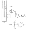
Die in Figur 1 schematisch dargestellte Anordnung zeigt einen Teil einer Vakuumpufferkammer 1 eines Magnetbandgerätes, in welcher sich eine Bandschlaufe 2 befindet. In der Rückwand der Pufferkammer 1 befindet sich in bekannter Weise ein mit kleinen Bohrungen zur Pufferkammer hin versehener Raum 10 (Mischkammer), in den die Schlauchleitung eines Druckwandlers 3 einmündet, um den Druck in der Mischkammer 10 zu messen. Dieser Druck ist abhängig von der Lage der Bandschlaufe 2 in der Pufferkammer. Es ist ein Temperaturfühler 4 vorgesehen, der eine von der Temperatur des Druckwandler 3 abhängige Spannung erzeugt. Diese Spannung wird dem einstellbaren Abgriff eines Potentiometers 5 zugeleitet, das zwischen die beiden Eingänge eines Differenzverstärkers 6 geschaltet ist. Der Ausgang des Differenzverstärkers 6 ist zusammen mit dem Ausgang des Druckwandlers 3 an den Eingang eines Operationsverstärkers 7 angeschlossen, dessen Ausgangssignal über einen Endverstärker 8 den der Vakuumpufferkammer 1 zugeordneten Wikkelmotor 9 steuert.The arrangement shown schematically in FIG. 1 shows part of a vacuum buffer chamber 1 of a magnetic tape device, in which a tape loop 2 is located. In the rear wall of the buffer chamber 1 there is, in a known manner, a space 10 (mixing chamber) with small bores towards the buffer chamber, into which the hose line of a pressure transducer 3 opens in order to measure the pressure in the mixing chamber 10. This pressure is dependent on the position of the belt loop 2 in the buffer chamber. A temperature sensor 4 is provided, which generates a voltage that is dependent on the temperature of the pressure converter 3. This voltage is fed to the adjustable tap of a potentiometer 5, which is connected between the two inputs of a
Figur 2 zeigt eine besonders vorteilhafte Ausführungsform für die Einrichtung 4. Diese besteht aus einem auf dem Druckwandler 3 selbst angeordneten Heissleiter 12, der mit einem Festwiderstand 11 elektrisch in Reihe geschaltet an einer festen Spannung +U, - U liegt und an dessen Verbindungspunkt A mit dem Festwiderstand 11 die temperaturabhängige Spannung abgegriffen wird.Figure 2 shows a particularly advantageous embodiment for the device 4. This is from a
Die in Figur 1 dargestellte und insbesondere in der Form der Figur 2 ausgeführte Einrichtung arbeitet folgendermassen: Der Spannungsteiler bestehend aus dem Heissleiter 12 und dem Festwiderstand 11 ist zweckmässigerweise so dimensioniert, dass bei Normaltemperatur am Punkt A ein Potential von Null Volt herrscht. In diesem Zustand wird die Ausgangsspannung des Operationsverstärkers 7 gemessen.The device shown in FIG. 1 and in particular in the form of FIG. 2 operates as follows: The voltage divider consisting of the
Nach Erwärmung des Druckwandlers und des auf ihm angeordneten Heissleiters 12 auf eine beliebige, im zulässigen Arbeitsbereich des Druckwandlers liegende Temperatur wird der dann am Ausgang des Operationsverstärkers 7 gemessene Wert mit dem Potentiometer 5 wieder auf den bei Normaltemperatur gemessenen Wert eingestellt. Die Höhe der Temperatur, bei der diese Neueinstellung erfolgt, ist im zulässigen Arbeitsbereich des Druckwandlers ohne Bedeutung, da sich in diesem Bereich sowohl die Ausgangsspannung des Druckwandlers als auch der Widerstand des Heissleiters 12 linear mit der Temperatur ändern. Mit dem Verändern der Einstellung des Potentiometers 5 werden damit zwei Gerade zur Deckung gebracht und es ist deshalb unerheblich, bei welcher Temperatur dies erfolgt.After the pressure transducer and the
Claims (2)
Priority Applications (1)
| Application Number | Priority Date | Filing Date | Title |
|---|---|---|---|
| AT79105148T ATE1122T1 (en) | 1979-04-06 | 1979-12-13 | DEVICE FOR OVERRULING TEMPERATURE-CREATED OUTPUT VOLTAGE DEVIATIONS OF A PRESSURE TRANSDUCER IN MAGNETIC TAPE DEVICE. |
Applications Claiming Priority (2)
| Application Number | Priority Date | Filing Date | Title |
|---|---|---|---|
| DE2914037 | 1979-04-06 | ||
| DE2914037A DE2914037C2 (en) | 1979-04-06 | 1979-04-06 | Device for rendering ineffective deviations in the output voltage of a pressure transducer in magnetic tape recorders caused by temperature fluctuations |
Publications (2)
| Publication Number | Publication Date |
|---|---|
| EP0016866A1 EP0016866A1 (en) | 1980-10-15 |
| EP0016866B1 true EP0016866B1 (en) | 1982-05-26 |
Family
ID=6067703
Family Applications (1)
| Application Number | Title | Priority Date | Filing Date |
|---|---|---|---|
| EP79105148A Expired EP0016866B1 (en) | 1979-04-06 | 1979-12-13 | Device to render ineffective output-voltage deviations of a pressure transducer in magnetic tape apparatuses caused by fluctuations in temperature |
Country Status (4)
| Country | Link |
|---|---|
| US (1) | US4306689A (en) |
| EP (1) | EP0016866B1 (en) |
| AT (1) | ATE1122T1 (en) |
| DE (1) | DE2914037C2 (en) |
Cited By (1)
| Publication number | Priority date | Publication date | Assignee | Title |
|---|---|---|---|---|
| US6074629A (en) * | 1998-07-27 | 2000-06-13 | J. M. Huber Corporation | Dentifrice with a dye absorbing silica for imparting a speckled appearance thereto |
Families Citing this family (3)
| Publication number | Priority date | Publication date | Assignee | Title |
|---|---|---|---|---|
| DE3431517C2 (en) * | 1984-08-28 | 1986-09-04 | Kernforschungsanlage Jülich GmbH, 5170 Jülich | Method for measuring pressure with a gas friction vacuum meter and a gas friction vacuum meter for carrying out the method |
| JP3187819B2 (en) * | 1990-01-26 | 2001-07-16 | ソニー株式会社 | Tape tension control device |
| US5228635A (en) * | 1990-01-26 | 1993-07-20 | Sony Corporation | Apparatus having a vacuum chamber for controlling a tape tension thereof/vacuum chamber apparatus for controlling tape tension |
Family Cites Families (6)
| Publication number | Priority date | Publication date | Assignee | Title |
|---|---|---|---|---|
| US3354318A (en) * | 1964-04-20 | 1967-11-21 | Ampex | Loop sensing system for magnetic tape transports wherein loop intercepts light beam |
| GB1195121A (en) * | 1967-05-16 | 1970-06-17 | Int Computers Ltd | Improvements in or relating to Position Sensing Apparatus. |
| US3701494A (en) * | 1970-04-20 | 1972-10-31 | Honeywell Inc | Electropneumatically controlled servo for tape mechanism |
| US3967188A (en) * | 1973-05-24 | 1976-06-29 | Bell & Howell Company | Temperature compensation circuit for sensor of physical variables such as temperature and pressure |
| CH616743A5 (en) * | 1977-07-01 | 1980-04-15 | Bbc Brown Boveri & Cie | Device for measuring the density of gaseous media. |
| DE2840957B1 (en) * | 1978-09-20 | 1980-01-24 | Siemens Ag | Device for disabling deviations in the output voltage of a pressure transducer in magnetic tape devices caused by temperature fluctuations |
-
1979
- 1979-04-06 DE DE2914037A patent/DE2914037C2/en not_active Expired
- 1979-12-13 EP EP79105148A patent/EP0016866B1/en not_active Expired
- 1979-12-13 AT AT79105148T patent/ATE1122T1/en not_active IP Right Cessation
-
1980
- 1980-02-25 US US06/123,985 patent/US4306689A/en not_active Expired - Lifetime
Cited By (1)
| Publication number | Priority date | Publication date | Assignee | Title |
|---|---|---|---|---|
| US6074629A (en) * | 1998-07-27 | 2000-06-13 | J. M. Huber Corporation | Dentifrice with a dye absorbing silica for imparting a speckled appearance thereto |
Also Published As
| Publication number | Publication date |
|---|---|
| ATE1122T1 (en) | 1982-06-15 |
| EP0016866A1 (en) | 1980-10-15 |
| US4306689A (en) | 1981-12-22 |
| DE2914037C2 (en) | 1983-12-08 |
| DE2914037A1 (en) | 1980-10-16 |
Similar Documents
| Publication | Publication Date | Title |
|---|---|---|
| DE3531118A1 (en) | METHOD FOR ERROR COMPENSATION FOR MEASURING VALVE WITH NON-LINEAR CHARACTERISTICS, AND ARRANGEMENT FOR IMPLEMENTING THE METHOD | |
| EP0869335A2 (en) | Device and method for measuring and controlling the flowrate of a fluid | |
| DE2139999A1 (en) | Status sensor circuit in bridge arrangement | |
| DE2105357A1 (en) | Device for measuring the flow of media flowing in pipes | |
| EP0016866B1 (en) | Device to render ineffective output-voltage deviations of a pressure transducer in magnetic tape apparatuses caused by fluctuations in temperature | |
| DE102007053943A1 (en) | Thermal conduction-gas pressure measuring instrument i.e. vacuum measuring instrument, has feedback unit e.g. switching transistor, connecting and separating control signals to and from Wheatstone bridge circuit, respectively | |
| DE3016985A1 (en) | ELECTRICAL MEASURING TRANSMITTER WITH A DEVICE FOR CODING A PARAMETER THEREOF | |
| DE10102791A1 (en) | Electrical transmitter | |
| DE2840957C2 (en) | ||
| CH616743A5 (en) | Device for measuring the density of gaseous media. | |
| DE2203306C2 (en) | Circuit arrangement for zero point shifting of measuring voltages | |
| DE2641795C3 (en) | Device for measuring and regulating pressures or differential pressures | |
| EP0249797B1 (en) | Pressure-regulating valve | |
| DE2163749C3 (en) | Method for eliminating the temperature effects of a circuit arrangement with non-linear characteristics | |
| DE2451281C3 (en) | Measuring amplifier | |
| DE3313043A1 (en) | Circuit arrangement for measuring a multiplicity of slowly varying operating temperatures | |
| DE3024328A1 (en) | Measuring physical value using parallel electrical model - reducing measurement delay using auxiliary sensor and differential circuit | |
| DE1007510B (en) | Compensation device for measuring or recording a physical quantity | |
| DE2453704C2 (en) | Circuit arrangement of a signal amplifier for a signal generated by means of a measuring bridge | |
| EP1378063A2 (en) | Method and circuit for linearising non-linear curves | |
| DE1573718C (en) | Testing machine with control of the test force based on a given target value | |
| DE19635162A1 (en) | Measurement device | |
| DE1934252C3 (en) | Circuit arrangement for operating several control loops in synchronism | |
| DE2125854C3 (en) | Electrical circuit arrangement for a speed control device of a gas turbine plant | |
| DE2100775A1 (en) | Device for linearizing resistance measurements |
Legal Events
| Date | Code | Title | Description |
|---|---|---|---|
| PUAI | Public reference made under article 153(3) epc to a published international application that has entered the european phase |
Free format text: ORIGINAL CODE: 0009012 |
|
| AK | Designated contracting states |
Designated state(s): AT BE CH FR GB IT NL |
|
| 17P | Request for examination filed |
Effective date: 19801029 |
|
| ITF | It: translation for a ep patent filed |
Owner name: STUDIO JAUMANN |
|
| GRAA | (expected) grant |
Free format text: ORIGINAL CODE: 0009210 |
|
| AK | Designated contracting states |
Designated state(s): AT BE CH FR GB IT NL |
|
| REF | Corresponds to: |
Ref document number: 1122 Country of ref document: AT Date of ref document: 19820615 Kind code of ref document: T |
|
| PGFP | Annual fee paid to national office [announced via postgrant information from national office to epo] |
Ref country code: CH Payment date: 19830228 Year of fee payment: 4 |
|
| PGFP | Annual fee paid to national office [announced via postgrant information from national office to epo] |
Ref country code: AT Payment date: 19831202 Year of fee payment: 5 |
|
| PGFP | Annual fee paid to national office [announced via postgrant information from national office to epo] |
Ref country code: NL Payment date: 19831220 Year of fee payment: 5 |
|
| PG25 | Lapsed in a contracting state [announced via postgrant information from national office to epo] |
Ref country code: CH Effective date: 19831231 Ref country code: BE Effective date: 19831231 |
|
| PGFP | Annual fee paid to national office [announced via postgrant information from national office to epo] |
Ref country code: BE Payment date: 19831231 Year of fee payment: 5 |
|
| REG | Reference to a national code |
Ref country code: CH Ref legal event code: PL |
|
| PG25 | Lapsed in a contracting state [announced via postgrant information from national office to epo] |
Ref country code: AT Effective date: 19841213 |
|
| PGFP | Annual fee paid to national office [announced via postgrant information from national office to epo] |
Ref country code: FR Payment date: 19841220 Year of fee payment: 6 |
|
| BERE | Be: lapsed |
Owner name: SIEMENS A.G. BERLIN UND MUNCHEN Effective date: 19841213 |
|
| PG25 | Lapsed in a contracting state [announced via postgrant information from national office to epo] |
Ref country code: NL Effective date: 19850701 |
|
| NLV4 | Nl: lapsed or anulled due to non-payment of the annual fee | ||
| GBPC | Gb: european patent ceased through non-payment of renewal fee | ||
| PG25 | Lapsed in a contracting state [announced via postgrant information from national office to epo] |
Ref country code: FR Free format text: LAPSE BECAUSE OF NON-PAYMENT OF DUE FEES Effective date: 19880831 |
|
| REG | Reference to a national code |
Ref country code: FR Ref legal event code: ST |
|
| PG25 | Lapsed in a contracting state [announced via postgrant information from national office to epo] |
Ref country code: GB Free format text: LAPSE BECAUSE OF NON-PAYMENT OF DUE FEES Effective date: 19881118 |
|
| PLBE | No opposition filed within time limit |
Free format text: ORIGINAL CODE: 0009261 |
|
| STAA | Information on the status of an ep patent application or granted ep patent |
Free format text: STATUS: NO OPPOSITION FILED WITHIN TIME LIMIT |