EP0012858A1 - Display and recording apparatus - Google Patents
Display and recording apparatus Download PDFInfo
- Publication number
- EP0012858A1 EP0012858A1 EP79104714A EP79104714A EP0012858A1 EP 0012858 A1 EP0012858 A1 EP 0012858A1 EP 79104714 A EP79104714 A EP 79104714A EP 79104714 A EP79104714 A EP 79104714A EP 0012858 A1 EP0012858 A1 EP 0012858A1
- Authority
- EP
- European Patent Office
- Prior art keywords
- data
- crt
- row
- printer
- Prior art date
- Legal status (The legal status is an assumption and is not a legal conclusion. Google has not performed a legal analysis and makes no representation as to the accuracy of the status listed.)
- Granted
Links
Images


Classifications
-
- G—PHYSICS
- G06—COMPUTING; CALCULATING OR COUNTING
- G06K—GRAPHICAL DATA READING; PRESENTATION OF DATA; RECORD CARRIERS; HANDLING RECORD CARRIERS
- G06K15/00—Arrangements for producing a permanent visual presentation of the output data, e.g. computer output printers
- G06K15/02—Arrangements for producing a permanent visual presentation of the output data, e.g. computer output printers using printers
- G06K15/10—Arrangements for producing a permanent visual presentation of the output data, e.g. computer output printers using printers by matrix printers
-
- B—PERFORMING OPERATIONS; TRANSPORTING
- B41—PRINTING; LINING MACHINES; TYPEWRITERS; STAMPS
- B41J—TYPEWRITERS; SELECTIVE PRINTING MECHANISMS, i.e. MECHANISMS PRINTING OTHERWISE THAN FROM A FORME; CORRECTION OF TYPOGRAPHICAL ERRORS
- B41J2/00—Typewriters or selective printing mechanisms characterised by the printing or marking process for which they are designed
- B41J2/315—Typewriters or selective printing mechanisms characterised by the printing or marking process for which they are designed characterised by selective application of heat to a heat sensitive printing or impression-transfer material
- B41J2/32—Typewriters or selective printing mechanisms characterised by the printing or marking process for which they are designed characterised by selective application of heat to a heat sensitive printing or impression-transfer material using thermal heads
- B41J2/35—Typewriters or selective printing mechanisms characterised by the printing or marking process for which they are designed characterised by selective application of heat to a heat sensitive printing or impression-transfer material using thermal heads providing current or voltage to the thermal head
-
- G—PHYSICS
- G06—COMPUTING; CALCULATING OR COUNTING
- G06K—GRAPHICAL DATA READING; PRESENTATION OF DATA; RECORD CARRIERS; HANDLING RECORD CARRIERS
- G06K15/00—Arrangements for producing a permanent visual presentation of the output data, e.g. computer output printers
- G06K15/02—Arrangements for producing a permanent visual presentation of the output data, e.g. computer output printers using printers
- G06K15/028—Arrangements for producing a permanent visual presentation of the output data, e.g. computer output printers using printers by thermal printers
-
- G—PHYSICS
- G06—COMPUTING; CALCULATING OR COUNTING
- G06K—GRAPHICAL DATA READING; PRESENTATION OF DATA; RECORD CARRIERS; HANDLING RECORD CARRIERS
- G06K2215/00—Arrangements for producing a permanent visual presentation of the output data
- G06K2215/0082—Architecture adapted for a particular function
- G06K2215/0091—Outputting only video data, e.g. Hard copy of CRT display
Definitions
- This invention relates to display and recording apparatus.
- the printer display of the present invention provides a low cost, quiet, compact, single hard copy output of CRT displayed information.
- a line-of-dots thermal printer with a solid state print head
- screen information is printed on-the-fly on thermally sensitive roll paper fed past the print head by a motor driven platen.
- the printer uses the same serial data that the display control circuitry transmits to the cathode ray tube for visual display.
- One line of data is gated to the print buffer and printed during each refresh cycle by a line of thermal print dots equal in number to the number of dots in each raster scan line of data.
- the printer thereby prints the content of the display screen without the necessity of duplicating the character generator circuit and other circuitry for preparation of data in serial bit form.
- the printer is also insensitive to whether the scan data is from a device that scans raster lines sequentially or utilizes an interlaced raster.
- all points addressable characteristic of the printer affords versatile printing capability as the device is able to reproduce graphics with the same ease as characters or symbols, allowing for ease in interface and attachment.
- the invention provides apparatus for displaying an image represented by a serial sequence of data, said apparatus comprising a CRT display device including control circuitry for deriving from said serial data control signals for controlling the CRT to cause the display device to display the image; dot printing means operable to print dots at selected positions in a matrix of dot positions covering an image receiving area of a record medium; and connecting circuitry connecting the printer to the display device and operative to supply the CRT control signals as control signals to the printer to cause the printer to print the image displayed by the CRT display device.
- the printing means is a thermal printer or an electro-erosion printer.
- the invention also provides in combination with a CRT display device of the type wherein serial raster data is provided on a line basis to a CRT screen, a thermal printer for printing the screen display information on a thermo graphic medium comprising thermal print means including a row of thermal print elements having a print element for each dot position of a raster scan row on said CRT screen, print control circuit means for actuating said thermal print elements of said thermal print means, and gating means interconnecting said display device and said print control circuit means for sequentially gating lines of said serial raster data to said print control circuit means in parallel with transmission to said CRT screen.
- the printer 11 includes a control panel 12, a print head card 13 mounted on a stiffener or frame 14, a paper cradle 15 that carries a platen 17 and a driving motor 19 (FIG. 2), and a power supply 20 on which is mounted an interface logic card 22.
- a control panel 12 controls the print head card 13 and the print head card 13.
- a paper cradle 15 that carries a platen 17 and a driving motor 19 (FIG. 2)
- a power supply 20 on which is mounted an interface logic card 22.
- Each of these assemblies is mounted on and carried by a frame 24.
- the control panel 12 carries the operating switches and indicator signals. Exemplary of such would be a copy switch 26 to initiate a print cylce and indicator lights 27 indicative of operating conditions such as a data check, line sync or power on.
- a power supply 20 mounted on a formed metal plate 29 that provides both electrical shielding and a subframe for the power supply assembly.
- a printed circuit card 22 Secured to the plate 29 by stand off clips (not shown) is a printed circuit card 22 that carries the interface logic circuitry for printer 11.
- the paper cradle 15 has side walls 32, 33 interconnected by a curved wall 34 which forms a recess for receiving and confining a roll of paper.
- a platen 17 has a shaft 36 extending from each axial end and is mounted on side walls 32, 33 by bearings 37, 38 respectively which receive such shaft 36.
- a thumb wheel 39 is secured to one end of shaft 36 for movement in unison therewith to provide for manual advance of the paper.
- Adjacent the opposite end of shaft 36 is mounted a helicon face gear 41 which is retained between the shoulder 42 where shaft 36 is reduced in diameter and the collar 43 which includes a set screw 44 (FIG. 3) that engages a flatted surface 45 the shaft 36 in the assemblied condition.
- An overruning clutch 47 is pressed into the central bore of gear 41 and cooperates with shaft 36 to permit the shaft to rotate in a counter clockwise direction as viewed in FIG. 2 while preventing lockwise rotation.
- the platen 17 can thus be rotated to advance the paper media through maipulation of thumb wheel 39 independently of the movement of gear 41.
- Paper cradle 15 also has formed as an integral part thereof fpur apertured projections 55 which provide for mounting the paper cradle platen assembly on the printer frame 24. Projections 57 have upwardly facing U shaped openings 58 for receiving trunnions 59 of the print head card stiffener 14 (FIG. 4). Also formed as integral parts of the side walls 32, 33 are detent ridges 60.
- FIG. 4 shows the print head card stiffener 14 which is molded as a single part.
- the print head card 13 (FIG. 5) showvs the side which confronts the platen and is mounted on the stiffener at the rear of the side in FIG. 4.
- Print head card 13 is secured to stiffener 14 by either clips or screws (not illustrated) that extend through card apertures 62 and are received in stiffener bores 63 (some of which are visible).
- Print head card 13 is electrically connected to logic card 22 by a flat cable 65 and to the power supply 20 by cabling which is attached to voltage connector 66.
- the stiffener further includes trunnions 59 which are received in paper cradle openings 58 and detent recesses 67 in arms 68 which engage the detent ridges 60.
- Stiffener 14 also includes an upper portion 69 of wedge shaped cross section that presents a tear edge 70 for severing a projecting length of paper from the supply roll.
- stiffener 14 mounted on stiffener 14 are a series of eight spring elements 72 which have turned lower ends 73 that are received in and positioned by stiffener slots 74 and have upper ends 75 which engage the print head card 13 at the rear of the print heads 77 to urge the print heads toward platen 17 when in the assemblied operating condition to assure conforming contact with the thermal print paper 78 trained over platen 17.
- Print head card 13 terminates upwardly in 4 cantilevered portions separated by slots 81. Each cantilevered portion 80 carries one of the print heads 77.
- Print head card 13 contains the print circuitry to actuate and control the thermal print head 77.
- Voltage connector 66 interconnects the printer circuits with the power supply 20.
- the lines of the flat cable 65 interconnect the printer circuits on the print head card 13 with the interface logic on card 22 for receipt of control and data signals.
- the four print heads 77 present a continuous line of thermal print dots 82 which aggregate in total the number of themal dot positions forming one line of a dot matrix print line.
- Each print head comprises a metalized ceramic substrate 84, the land patterns of which are connected to the conductive land patterns of the printed circuit board forming the print head card 13.
- Print head card 13 carries a series of large scale integration (LSI) modules 86 which contain the print head drivers and other LSI modules 87 which contain address counters.
- LSI large scale integration
- the print head card 13 and the thermal print heads 77 are biased toward platen 17 in the operating conditon.
- the print head card assembly is biased toward tangency with the platen along the line of the thermal print dots 82 to hold the paper media captive therebetween causing the thermal print heads 77 to be the pressure pad that assures that the paper moves in unison with the platen surface while concurrently assuring closely conforming thermal printing contact between the print dots 82 and the thermal paper media 78.
- FIG. 8 shows a modified print head card stiffener 90 wherein the print head biasing elements 91 are molded as an integral part of the stiffener.
- Each of the elements 91 inclines slightly outward from the print head card mounting plane and includes at the distal end a semi-cylindrical projection 92 that engages the confronting thermal print head centrally at its rear surface and rockably biases the print head toward close conformity with the platen surface and thermally sensitive paper 78.
- Each of the thermal print heads 77 is mounted on a cantilevered projection 80 separated from the adjoining projection by a slot 81.
- the cantilevered projections 80 afford sufficient flexibility to enable torsional adjustment induced by the biasing elements 91 to achieve the necessary adjustment.
- the mode of operation of the printer in printing a sequence of lines of thermal print dots enables the device to print out the content of a CRT screen display by printing a sequence of lines on the thermal print medium 78 which reproduces the sequence of raster lines of dots on the CRT screen. This is accomplished by the printer shown and described herein by printing one raster line of data during each refresh cycle of the CRT. The use of successive refresh cycles also makes it immaterial whether the CRT refreshes successive lines or uses an interlaced raster.
- the printer logic circuits are also simplified in this approach to a CRT screen print application since the serial data supplied to the CRT is used concurrently by the printer eliminating the need for duplicate character generators and associated circuitry.
- FIG. 10 schematically illustrates the circuit relationship between a raster scan CRT display and the thermal screen printer.
- the display controller includes row buffers 94 that are loaded from a random access memory (not shown).
- Serial output on line 98 from a serializer within attribute control and video 95 is generated using data from character generator 96 and control from control and timing circuits 97.
- the serializer output data on line 98 which goes to CRT 99 is also transmitted to the display printer data storage and control 100 from which it is multiplexed and transmitted to the thermal print circuits 101.
- FIG. 7 illustrates logic circuitry for adapting the printer for the output printing of the content of a raster scan CRT display.
- the serial data on line 98 transmitted to the CRT is also connected to a deserializer shift register 102.
- the serial data to the CRT is continuously received also by the shift register 102 but is gated to buffer 103 only when a print operation is occurring and the data associated with the line to be printed is being received by shift register 102.
- the serial data is transferred from register 102 to buffer 103 and from there is stored in the random access memory (RAM) 104 until the 800 bits for one line of thermal dot printing have been received.
- the line of data is transmitted to the print head 77 by the multiplexer circuits 105.
- the multiplexer 105 selectively gates the data to the thermal print dot drivers in accordance with the needs of the system.
- the thermal print dots 82 constitute one continuous row of dots transverse to the direction of motion of the paper media or one raster oAo the CRT screen, various blocks of print dots are often staggered in the direction of paper travel to enable non simultaneous actuation. This is accommodated by the multiplexer to cause all dots in one line of data to appear on a single straight line on the print media.
- Various control signals are also received by the printer timing and control circuitry 107 from the CRT display control logic to enable the printer to coordinate the printing of the data on the CRT.
- the printer control logic also controls the start and stop of the platen drive motor 19. The motor speed is coordinated to the print operation to cause the paper to advance a distance between the lines of printed dots approximately equal to the distance between adjacent dots with any line of dots. Thereby the aspect ratio is maintained between characters or other information displayed on the CRT screen and printed on the thermal print medium to give a faithful reproduction.
- the printer Since the printer prints all the information appearing the CRT screen on a raster dot basis, the printer is not sensitive to language, character or symbols and will also print equally accurately graphic information. In some circumstances it may be desired not to print all indicia appearing on the CRT screen. For example, displayed characters may each appear within a dot matrix defined within a larger matrix which also includes a character boundary or space between adjoining characters. This space or character boundary may be used for displaying prompting, field information or character position within a field. When it is not desired that such information appear in the printed record of the screen content it will be necessary to interpose a control circuit to selectively suppress the printer operation An example is shown in FIG. 9.
- AND block 110 is used to suppress the printing of data or information found in the character boundary space; however the boundary space is illuminated by satisfying AND block 11 when a reverse image signal is present to prevent a distortion of the screen image when it is desired to display dark or blanked characters on an illuminated or unblanked background.
Abstract
Description
- This invention relates to display and recording apparatus.
- Previously when it has been desired to print the content of a display screen to provide a permanent hard copy it has been necessary to transfer the data content of the display to a memory and thereafter use the stored data as the basis for actuating a printer to generate a hard copy. This involved discrimination between displayable characters and other data, character generation and data manipulation for display or print in both devices thereby duplicating numerous functions.
- The printer display of the present invention provides a low cost, quiet, compact, single hard copy output of CRT displayed information. Using a line-of-dots thermal printer with a solid state print head, screen information is printed on-the-fly on thermally sensitive roll paper fed past the print head by a motor driven platen. The printer uses the same serial data that the display control circuitry transmits to the cathode ray tube for visual display. One line of data is gated to the print buffer and printed during each refresh cycle by a line of thermal print dots equal in number to the number of dots in each raster scan line of data. The printer thereby prints the content of the display screen without the necessity of duplicating the character generator circuit and other circuitry for preparation of data in serial bit form. The printer is also insensitive to whether the scan data is from a device that scans raster lines sequentially or utilizes an interlaced raster. In addition the all points addressable characteristic of the printer affords versatile printing capability as the device is able to reproduce graphics with the same ease as characters or symbols, allowing for ease in interface and attachment.
- Accordingly the invention provides apparatus for displaying an image represented by a serial sequence of data, said apparatus comprising a CRT display device including control circuitry for deriving from said serial data control signals for controlling the CRT to cause the display device to display the image; dot printing means operable to print dots at selected positions in a matrix of dot positions covering an image receiving area of a record medium; and connecting circuitry connecting the printer to the display device and operative to supply the CRT control signals as control signals to the printer to cause the printer to print the image displayed by the CRT display device.
- Preferably the printing means is a thermal printer or an electro-erosion printer.
- The invention also provides in combination with a CRT display device of the type wherein serial raster data is provided on a line basis to a CRT screen, a thermal printer for printing the screen display information on a thermo graphic medium comprising thermal print means including a row of thermal print elements having a print element for each dot position of a raster scan row on said CRT screen, print control circuit means for actuating said thermal print elements of said thermal print means, and gating means interconnecting said display device and said print control circuit means for sequentially gating lines of said serial raster data to said print control circuit means in parallel with transmission to said CRT screen.
- The invention will now be more particularly described with reference to the accompanying drawings, in which:-
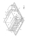
- FIG. 1 is an isometric view of apparatus embodying the present invention showing the apparatus frame and subassemblies mounted thereon, the view being with the cover removed.
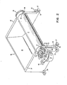
- FIG. 2 is an isometric view of the platen, drive motor and paper cradle subassembly of FIG. 1.
- FIG. 3 is a section view through the axis of the helicon platen drive gear of FIG. 2 also including the overrunning clutch for one way drive of the platen shaft.
- FIG. 4 is an isometric view of the stiffener for mounting thepriht head card.
- FIG. 5 is an elevation of the print head card.
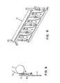
- FIG. 6 is'a side elevation of the print head card print head assembly showing its cooperation with the platen and thermal print media.
- FIG. 7 is a schematic circuit diagram showing the printer interface logic for handling data from an associated display.
- FIG. 8 is an alternative embodiment for the stiffener of FIG. 4 showing the biasing structure molded as an integral part thereof.
- FIG. 9 is a circuit for modification of the serial output data received by the printer to selectively eliminate non- character information on the display screen from the printed hard copy output.
- FIG. 10 is a schematic logic circuit showing portions of the display and associated printer circuitry.
- The printer 11 includes a
control panel 12, aprint head card 13 mounted on a stiffener orframe 14, apaper cradle 15 that carries aplaten 17 and a driving motor 19 (FIG. 2), and apower supply 20 on which is mounted an interface logic card 22. Each of these assemblies is mounted on and carried by aframe 24. - The
control panel 12 carries the operating switches and indicator signals. Exemplary of such would be a copy switch 26 to initiate a print cylce andindicator lights 27 indicative of operating conditions such as a data check, line sync or power on. - At the rear of the printer assembly is a
power supply 20 mounted on a formedmetal plate 29 that provides both electrical shielding and a subframe for the power supply assembly. Secured to theplate 29 by stand off clips (not shown) is a printed circuit card 22 that carries the interface logic circuitry for printer 11. - As shown in FIG. 2, the
paper cradle 15 hasside walls curved wall 34 which forms a recess for receiving and confining a roll of paper. Aplaten 17 has ashaft 36 extending from each axial end and is mounted onside walls bearings such shaft 36. Athumb wheel 39 is secured to one end ofshaft 36 for movement in unison therewith to provide for manual advance of the paper. Adjacent the opposite end ofshaft 36 is mounted ahelicon face gear 41 which is retained between theshoulder 42 whereshaft 36 is reduced in diameter and thecollar 43 which includes a set screw 44 (FIG. 3) that engages aflatted surface 45 theshaft 36 in the assemblied condition. Anoverruning clutch 47 is pressed into the central bore ofgear 41 and cooperates withshaft 36 to permit the shaft to rotate in a counter clockwise direction as viewed in FIG. 2 while preventing lockwise rotation. Theplaten 17 can thus be rotated to advance the paper media through maipulation ofthumb wheel 39 independently of the movement ofgear 41. - Mounted on
ears wide wall 32 and formed as an integral part thereof is asynchronous motor 19. Theoutput shaft 51 ofmotor 19 carries a helicon pinion orworm gear 53 that engagesface gear 41 to impart rotatary motion to platen 17.Paper cradle 15 also has formed as an integral part thereof fpur aperturedprojections 55 which provide for mounting the paper cradle platen assembly on theprinter frame 24.Projections 57 have upwardly facing U shapedopenings 58 for receivingtrunnions 59 of the print head card stiffener 14 (FIG. 4). Also formed as integral parts of theside walls detent ridges 60. - FIG. 4 shows the print
head card stiffener 14 which is molded as a single part. The print head card 13 (FIG. 5) showvs the side which confronts the platen and is mounted on the stiffener at the rear of the side in FIG. 4. Printhead card 13 is secured to stiffener 14 by either clips or screws (not illustrated) that extend throughcard apertures 62 and are received in stiffener bores 63 (some of which are visible). Printhead card 13 is electrically connected to logic card 22 by aflat cable 65 and to thepower supply 20 by cabling which is attached tovoltage connector 66. The stiffener further includestrunnions 59 which are received inpaper cradle openings 58 anddetent recesses 67 inarms 68 which engage thedetent ridges 60. Thetrunions 59 and detents 67 function to retain theprint head card 13 mounted onstiffener 14 in an operatingposition confronting platen 17. Stiffener 14 also includes anupper portion 69 of wedge shaped cross section that presents atear edge 70 for severing a projecting length of paper from the supply roll. Mounted onstiffener 14 are a series of eightspring elements 72 which have turnedlower ends 73 that are received in and positioned bystiffener slots 74 and haveupper ends 75 which engage theprint head card 13 at the rear of theprint heads 77 to urge the print heads towardplaten 17 when in the assemblied operating condition to assure conforming contact with thethermal print paper 78 trained overplaten 17. Printhead card 13 terminates upwardly in 4 cantilevered portions separated byslots 81. Eachcantilevered portion 80 carries one of theprint heads 77. - Print
head card 13 contains the print circuitry to actuate and control thethermal print head 77.Voltage connector 66 interconnects the printer circuits with thepower supply 20. The lines of theflat cable 65 interconnect the printer circuits on theprint head card 13 with the interface logic on card 22 for receipt of control and data signals. The fourprint heads 77 present a continuous line ofthermal print dots 82 which aggregate in total the number of themal dot positions forming one line of a dot matrix print line. Each print head comprises a metalizedceramic substrate 84, the land patterns of which are connected to the conductive land patterns of the printed circuit board forming theprint head card 13. Printhead card 13 carries a series of large scale integration (LSI)modules 86 which contain the print head drivers andother LSI modules 87 which contain address counters. - As seen in FIG. 6 the
print head card 13 and thethermal print heads 77 are biased towardplaten 17 in the operating conditon. The print head card assembly is biased toward tangency with the platen along the line of thethermal print dots 82 to hold the paper media captive therebetween causing thethermal print heads 77 to be the pressure pad that assures that the paper moves in unison with the platen surface while concurrently assuring closely conforming thermal printing contact between theprint dots 82 and thethermal paper media 78. - FIG. 8 shows a modified print
head card stiffener 90 wherein the print head biasing elements 91 are molded as an integral part of the stiffener. Each of the elements 91 inclines slightly outward from the print head card mounting plane and includes at the distal end asemi-cylindrical projection 92 that engages the confronting thermal print head centrally at its rear surface and rockably biases the print head toward close conformity with the platen surface and thermallysensitive paper 78. Each of thethermal print heads 77 is mounted on acantilevered projection 80 separated from the adjoining projection by aslot 81. Thecantilevered projections 80 afford sufficient flexibility to enable torsional adjustment induced by the biasing elements 91 to achieve the necessary adjustment. - The mode of operation of the printer in printing a sequence of lines of thermal print dots enables the device to print out the content of a CRT screen display by printing a sequence of lines on the
thermal print medium 78 which reproduces the sequence of raster lines of dots on the CRT screen. This is accomplished by the printer shown and described herein by printing one raster line of data during each refresh cycle of the CRT. The use of successive refresh cycles also makes it immaterial whether the CRT refreshes successive lines or uses an interlaced raster. The printer logic circuits are also simplified in this approach to a CRT screen print application since the serial data supplied to the CRT is used concurrently by the printer eliminating the need for duplicate character generators and associated circuitry. - FIG. 10 schematically illustrates the circuit relationship between a raster scan CRT display and the thermal screen printer. The display controller includes row buffers 94 that are loaded from a random access memory (not shown). Serial output on
line 98 from a serializer within attribute control andvideo 95 is generated using data fromcharacter generator 96 and control from control and timingcircuits 97. The serializer output data online 98 which goes toCRT 99 is also transmitted to the display printer data storage andcontrol 100 from which it is multiplexed and transmitted to thethermal print circuits 101. - FIG. 7 illustrates logic circuitry for adapting the printer for the output printing of the content of a raster scan CRT display. The serial data on
line 98 transmitted to the CRT is also connected to adeserializer shift register 102. The serial data to the CRT is continuously received also by theshift register 102 but is gated to buffer 103 only when a print operation is occurring and the data associated with the line to be printed is being received byshift register 102. The serial data is transferred fromregister 102 to buffer 103 and from there is stored in the random access memory (RAM) 104 until the 800 bits for one line of thermal dot printing have been received. The line of data is transmitted to theprint head 77 by themultiplexer circuits 105. Themultiplexer 105 selectively gates the data to the thermal print dot drivers in accordance with the needs of the system. Although thethermal print dots 82 constitute one continuous row of dots transverse to the direction of motion of the paper media or one raster oAo the CRT screen, various blocks of print dots are often staggered in the direction of paper travel to enable non simultaneous actuation. This is accommodated by the multiplexer to cause all dots in one line of data to appear on a single straight line on the print media. - Various control signals are also received by the printer timing and
control circuitry 107 from the CRT display control logic to enable the printer to coordinate the printing of the data on the CRT. In addition to receiving, selecting, storing and multiplexing the print data, the printer control logic also controls the start and stop of theplaten drive motor 19. The motor speed is coordinated to the print operation to cause the paper to advance a distance between the lines of printed dots approximately equal to the distance between adjacent dots with any line of dots. Thereby the aspect ratio is maintained between characters or other information displayed on the CRT screen and printed on the thermal print medium to give a faithful reproduction. - Since the printer prints all the information appearing the CRT screen on a raster dot basis, the printer is not sensitive to language, character or symbols and will also print equally accurately graphic information. In some circumstances it may be desired not to print all indicia appearing on the CRT screen. For example, displayed characters may each appear within a dot matrix defined within a larger matrix which also includes a character boundary or space between adjoining characters. This space or character boundary may be used for displaying prompting, field information or character position within a field. When it is not desired that such information appear in the printed record of the screen content it will be necessary to interpose a control circuit to selectively suppress the printer operation An example is shown in FIG. 9. Here AND block 110 is used to suppress the printing of data or information found in the character boundary space; however the boundary space is illuminated by satisfying AND block 11 when a reverse image signal is present to prevent a distortion of the screen image when it is desired to display dark or blanked characters on an illuminated or unblanked background.
- While the preferred embodiments of the invention have been illustrated and described in the foregoing, it is to be understood that it is not intended that the invention be limited to the precise constructions herein disclosed.
Claims (10)
Applications Claiming Priority (2)
| Application Number | Priority Date | Filing Date | Title |
|---|---|---|---|
| US97321278A | 1978-12-26 | 1978-12-26 | |
| US973212 | 1978-12-26 |
Publications (2)
| Publication Number | Publication Date |
|---|---|
| EP0012858A1 true EP0012858A1 (en) | 1980-07-09 |
| EP0012858B1 EP0012858B1 (en) | 1984-05-02 |
Family
ID=25520628
Family Applications (1)
| Application Number | Title | Priority Date | Filing Date |
|---|---|---|---|
| EP79104714A Expired EP0012858B1 (en) | 1978-12-26 | 1979-11-27 | Display and recording apparatus |
Country Status (4)
| Country | Link |
|---|---|
| US (1) | US4334231A (en) |
| EP (1) | EP0012858B1 (en) |
| JP (1) | JPS5587290A (en) |
| DE (1) | DE2966960D1 (en) |
Cited By (11)
| Publication number | Priority date | Publication date | Assignee | Title |
|---|---|---|---|---|
| FR2491279A1 (en) * | 1980-09-30 | 1982-04-02 | Sony Corp | PRINTING APPARATUS FOR PRODUCING A PRINTED DOCUMENT OF A GRAPHIC REPRESENTATION FORMED ON THE SCREEN OF A TELEVISION RECEIVER |
| EP0066728A1 (en) * | 1981-06-09 | 1982-12-15 | International Business Machines Corporation | Arrangement for preparing raster-scanned screen data for a print output |
| EP0081096A2 (en) * | 1981-12-04 | 1983-06-15 | International Business Machines Corporation | Image rotate control circuitry |
| EP0083424A1 (en) * | 1982-01-04 | 1983-07-13 | International Business Machines Corporation | Line printer attachment |
| EP0099469A2 (en) * | 1982-06-24 | 1984-02-01 | Loewe Opta Gmbh | System for the representation of text, graphics and symbols on monitor screens and/or with matrix printers |
| EP0110180A1 (en) * | 1982-11-26 | 1984-06-13 | International Business Machines Corporation | Storage apparatus for video data |
| EP0125878A2 (en) * | 1983-05-13 | 1984-11-21 | Ing. C. Olivetti & C., S.p.A. | Print apparatus for videotext terminal |
| EP0142032A1 (en) * | 1983-11-10 | 1985-05-22 | International Business Machines Corporation | Combined computer-controlled printer/copier system |
| GB2201378A (en) * | 1987-02-27 | 1988-09-01 | Astro Med Inc | Thermal dot matrix recorders |
| US4836697A (en) * | 1988-03-21 | 1989-06-06 | Kroy Inc. | Automated thermal transfer device and control system therefor |
| EP0321188A2 (en) * | 1987-12-14 | 1989-06-21 | Edgar L. Barth | Method and apparatus for decorating cakes and other foods |
Families Citing this family (9)
| Publication number | Priority date | Publication date | Assignee | Title |
|---|---|---|---|---|
| JPS5781785A (en) * | 1980-11-11 | 1982-05-21 | Toshiba Corp | Equipment for making hard copy from crt picture |
| JPH0764085B2 (en) * | 1981-06-08 | 1995-07-12 | 富士ゼロックス株式会社 | Thermal recording device |
| AU567487B2 (en) * | 1982-01-25 | 1987-11-26 | Sony Corporation | Thermal printer |
| JPS599084A (en) * | 1982-07-09 | 1984-01-18 | Shinko Electric Co Ltd | Thermal multi-color printer |
| JPS6126049U (en) * | 1984-07-20 | 1986-02-17 | 紀伊産業株式会社 | Container opening/closing mechanism |
| US4723260A (en) * | 1985-01-04 | 1988-02-02 | Yoshibumi Mukai | Medical X-ray photographic apparatus |
| JPS62109006U (en) * | 1985-12-27 | 1987-07-11 | ||
| US4810852A (en) * | 1988-04-01 | 1989-03-07 | Dynamics Research Corporation | High-resolution thermal printhead and method of fabrication |
| JPH03253184A (en) * | 1990-03-02 | 1991-11-12 | Kowa Co | Picture recorder |
Citations (4)
| Publication number | Priority date | Publication date | Assignee | Title |
|---|---|---|---|---|
| FR2263111A1 (en) * | 1974-03-06 | 1975-10-03 | Bosch Gmbh Robert | Information recorder using electrosensitive metal paper - has group of individual writing electrodes electrically insulated from one another and separately controllable |
| GB1412467A (en) * | 1972-10-23 | 1975-11-05 | Mullard Ltd | Control system for a high speed page printer |
| US3951247A (en) * | 1973-12-28 | 1976-04-20 | Ing. C. Olivetti & C., S.P.A. | Electrothermal printing unit |
| DE2813640A1 (en) * | 1977-05-26 | 1978-11-30 | Robotron Veb K | Control of electronic display and print elements - using coding, transfer and display elements to generate required currents from duty cycle set by micro-processor |
Family Cites Families (4)
| Publication number | Priority date | Publication date | Assignee | Title |
|---|---|---|---|---|
| US3373437A (en) * | 1964-03-25 | 1968-03-12 | Richard G. Sweet | Fluid droplet recorder with a plurality of jets |
| JPS535785B2 (en) * | 1973-03-31 | 1978-03-02 | ||
| US4141018A (en) * | 1976-11-08 | 1979-02-20 | Tokyo Shibaura Electric Co., Ltd. | Thermal recording head and drive circuit |
| US4158203A (en) * | 1977-09-30 | 1979-06-12 | Buckeye International, Inc. | Arrangement for recording images appearing on a cathode ray tube |
-
1979
- 1979-10-03 JP JP12693379A patent/JPS5587290A/en active Granted
- 1979-11-27 DE DE7979104714T patent/DE2966960D1/en not_active Expired
- 1979-11-27 EP EP79104714A patent/EP0012858B1/en not_active Expired
-
1980
- 1980-04-28 US US06/144,499 patent/US4334231A/en not_active Expired - Lifetime
Patent Citations (4)
| Publication number | Priority date | Publication date | Assignee | Title |
|---|---|---|---|---|
| GB1412467A (en) * | 1972-10-23 | 1975-11-05 | Mullard Ltd | Control system for a high speed page printer |
| US3951247A (en) * | 1973-12-28 | 1976-04-20 | Ing. C. Olivetti & C., S.P.A. | Electrothermal printing unit |
| FR2263111A1 (en) * | 1974-03-06 | 1975-10-03 | Bosch Gmbh Robert | Information recorder using electrosensitive metal paper - has group of individual writing electrodes electrically insulated from one another and separately controllable |
| DE2813640A1 (en) * | 1977-05-26 | 1978-11-30 | Robotron Veb K | Control of electronic display and print elements - using coding, transfer and display elements to generate required currents from duty cycle set by micro-processor |
Non-Patent Citations (2)
| Title |
|---|
| IBM TECHNICAL DISCLOSURE BULLETIN Vol. 17, July 1974, No. 2, Armonk NY, US S. KAMBIC "Selectable Area Television Printer/Plotter", pages 565-567 * The entire article * * |
| IBM TECHNICAL DISCLOSURE BULLETIN Vol. 21, No. 1, June 1978, Armonk, NY, US D.L. REESE: "Card Support Assembly for Thermal Printer", pages 286-287 * The entire article * * |
Cited By (16)
| Publication number | Priority date | Publication date | Assignee | Title |
|---|---|---|---|---|
| FR2491279A1 (en) * | 1980-09-30 | 1982-04-02 | Sony Corp | PRINTING APPARATUS FOR PRODUCING A PRINTED DOCUMENT OF A GRAPHIC REPRESENTATION FORMED ON THE SCREEN OF A TELEVISION RECEIVER |
| EP0066728A1 (en) * | 1981-06-09 | 1982-12-15 | International Business Machines Corporation | Arrangement for preparing raster-scanned screen data for a print output |
| EP0081096A2 (en) * | 1981-12-04 | 1983-06-15 | International Business Machines Corporation | Image rotate control circuitry |
| EP0081096A3 (en) * | 1981-12-04 | 1984-04-25 | International Business Machines Corporation | Image rotate control circuitry |
| EP0083424A1 (en) * | 1982-01-04 | 1983-07-13 | International Business Machines Corporation | Line printer attachment |
| EP0099469A2 (en) * | 1982-06-24 | 1984-02-01 | Loewe Opta Gmbh | System for the representation of text, graphics and symbols on monitor screens and/or with matrix printers |
| EP0099469A3 (en) * | 1982-06-24 | 1986-04-09 | Loewe Opta Gmbh | Method and system for the representation of text, graphics and symbols on monitor screens and/or with matrix printers |
| EP0110180A1 (en) * | 1982-11-26 | 1984-06-13 | International Business Machines Corporation | Storage apparatus for video data |
| EP0125878A3 (en) * | 1983-05-13 | 1987-04-15 | Ing. C. Olivetti & C., S.P.A. | Print apparatus for videotext terminal |
| EP0125878A2 (en) * | 1983-05-13 | 1984-11-21 | Ing. C. Olivetti & C., S.p.A. | Print apparatus for videotext terminal |
| EP0142032A1 (en) * | 1983-11-10 | 1985-05-22 | International Business Machines Corporation | Combined computer-controlled printer/copier system |
| GB2201378A (en) * | 1987-02-27 | 1988-09-01 | Astro Med Inc | Thermal dot matrix recorders |
| GB2201378B (en) * | 1987-02-27 | 1991-12-11 | Astro Med Inc | Chart recorder having multiple thermal print heads |
| EP0321188A2 (en) * | 1987-12-14 | 1989-06-21 | Edgar L. Barth | Method and apparatus for decorating cakes and other foods |
| EP0321188A3 (en) * | 1987-12-14 | 1990-04-25 | Edgar L. Barth | Method and apparatus for decorating cakes and other foods |
| US4836697A (en) * | 1988-03-21 | 1989-06-06 | Kroy Inc. | Automated thermal transfer device and control system therefor |
Also Published As
| Publication number | Publication date |
|---|---|
| EP0012858B1 (en) | 1984-05-02 |
| JPS6123908B2 (en) | 1986-06-07 |
| DE2966960D1 (en) | 1984-06-07 |
| US4334231A (en) | 1982-06-08 |
| JPS5587290A (en) | 1980-07-01 |
Similar Documents
| Publication | Publication Date | Title |
|---|---|---|
| EP0012858A1 (en) | Display and recording apparatus | |
| US4194833A (en) | Electronic typewriter having an electronic display | |
| US4741634A (en) | Printer with variable head displacement | |
| JPH0356184B2 (en) | ||
| US4184063A (en) | Thermal printer write head assembly | |
| US5677714A (en) | Neighbor insentive pixel deletion method for printing high resolution image | |
| JPS5931750B2 (en) | pattern generator | |
| EP0016457B1 (en) | Crt hard copy apparatus | |
| CA1122474A (en) | Non impact display screen output printer | |
| JPS6133711B2 (en) | ||
| JPH0311273B2 (en) | ||
| US4484231A (en) | Printing apparatus | |
| JPS6116091B2 (en) | ||
| JPH0698789B2 (en) | Serial dot printer | |
| GB2157865A (en) | Dot printer | |
| JPH0347893Y2 (en) | ||
| US3948168A (en) | Digital printer | |
| JPS57144762A (en) | Monitor display system of photo-type setting machine | |
| JPS58124670A (en) | Recording type desk-top calculator | |
| JP3015374B2 (en) | Recording device and information processing method | |
| KR860006756A (en) | Dot Character Display | |
| JPH09131925A (en) | Manual scan type printer | |
| JPS5842465A (en) | Multi-color printer | |
| JPS6386961A (en) | Recorder | |
| JP2551792B2 (en) | Recording system of recorder |
Legal Events
| Date | Code | Title | Description |
|---|---|---|---|
| PUAI | Public reference made under article 153(3) epc to a published international application that has entered the european phase |
Free format text: ORIGINAL CODE: 0009012 |
|
| AK | Designated contracting states |
Designated state(s): DE FR GB IT |
|
| 17P | Request for examination filed | ||
| ITF | It: translation for a ep patent filed |
Owner name: IBM - DR. ARRABITO MICHELANGELO |
|
| GRAA | (expected) grant |
Free format text: ORIGINAL CODE: 0009210 |
|
| AK | Designated contracting states |
Designated state(s): DE FR GB IT |
|
| REF | Corresponds to: |
Ref document number: 2966960 Country of ref document: DE Date of ref document: 19840607 |
|
| ET | Fr: translation filed | ||
| PLBE | No opposition filed within time limit |
Free format text: ORIGINAL CODE: 0009261 |
|
| STAA | Information on the status of an ep patent application or granted ep patent |
Free format text: STATUS: NO OPPOSITION FILED WITHIN TIME LIMIT |
|
| 26N | No opposition filed | ||
| PGFP | Annual fee paid to national office [announced via postgrant information from national office to epo] |
Ref country code: FR Payment date: 19891025 Year of fee payment: 11 |
|
| PGFP | Annual fee paid to national office [announced via postgrant information from national office to epo] |
Ref country code: GB Payment date: 19891031 Year of fee payment: 11 |
|
| PGFP | Annual fee paid to national office [announced via postgrant information from national office to epo] |
Ref country code: DE Payment date: 19891130 Year of fee payment: 11 |
|
| PG25 | Lapsed in a contracting state [announced via postgrant information from national office to epo] |
Ref country code: GB Effective date: 19901127 |
|
| ITTA | It: last paid annual fee | ||
| GBPC | Gb: european patent ceased through non-payment of renewal fee | ||
| PG25 | Lapsed in a contracting state [announced via postgrant information from national office to epo] |
Ref country code: FR Effective date: 19910731 |
|
| PG25 | Lapsed in a contracting state [announced via postgrant information from national office to epo] |
Ref country code: DE Effective date: 19910801 |
|
| REG | Reference to a national code |
Ref country code: FR Ref legal event code: ST |