EP0006281A1 - Body implantable stimulator and connector therefor - Google Patents
Body implantable stimulator and connector therefor Download PDFInfo
- Publication number
- EP0006281A1 EP0006281A1 EP79300565A EP79300565A EP0006281A1 EP 0006281 A1 EP0006281 A1 EP 0006281A1 EP 79300565 A EP79300565 A EP 79300565A EP 79300565 A EP79300565 A EP 79300565A EP 0006281 A1 EP0006281 A1 EP 0006281A1
- Authority
- EP
- European Patent Office
- Prior art keywords
- terminal
- connector
- implantable stimulator
- output means
- body implantable
- Prior art date
- Legal status (The legal status is an assumption and is not a legal conclusion. Google has not performed a legal analysis and makes no representation as to the accuracy of the status listed.)
- Withdrawn
Links
Images
Classifications
-
- A—HUMAN NECESSITIES
- A61—MEDICAL OR VETERINARY SCIENCE; HYGIENE
- A61N—ELECTROTHERAPY; MAGNETOTHERAPY; RADIATION THERAPY; ULTRASOUND THERAPY
- A61N1/00—Electrotherapy; Circuits therefor
- A61N1/18—Applying electric currents by contact electrodes
- A61N1/32—Applying electric currents by contact electrodes alternating or intermittent currents
- A61N1/36—Applying electric currents by contact electrodes alternating or intermittent currents for stimulation
- A61N1/372—Arrangements in connection with the implantation of stimulators
- A61N1/375—Constructional arrangements, e.g. casings
- A61N1/3752—Details of casing-lead connections
Definitions
- This invention relates to a body implantable stimulator comprising a signal generator and a lead connector secured thereto.
- body implantable stimulators are known to the prior art, the most common being the cardiac or heart pacemaker.
- Such stimulators are formed of a separable electrical lead and a signal generator with provision being made to electrically and mechanically connect the lead anc generator to complete the stimulator unit.
- the above referenced application provides a preformed connector assembly thereby eliminating the necessity of forming that assembly in place, as by an epoxy casting process, for example. Additionally, in that assembly, the electrical connection between the connector assembly terminal and the signal generator requires manipulation of a wire to position it and a weld, or other similar process, to secure it in position. Thus, while the connector assembly of the above referenced application greatly reduces the handling necessary to form and complete a connector assembly on a signal generator unit, considerably handling remains necessary.
- the connector is pre- formed and mechanical fastener means are provided for securing the connector to the generator.
- mechanical fastener means are provided for securing the connector to the generator.
- the preformed connector is provided with first means, e.g. passageways which accept and guide the signal generator output connections (usually a feedthrough pin or pins) and preferably the electrical lead into electrical contact with a terminal in the connector.
- first means e.g. passageways which accept and guide the signal generator output connections (usually a feedthrough pin or pins) and preferably the electrical lead into electrical contact with a terminal in the connector.
- One or more terminals are provided with intersecting bores such that the feedthrough pin and electrical lead contact within the terminal or by means of it.
- Means are provided for securing the lead within the terminal. For example, this may be accomplished via a set screw which engages the lead to urge it against the terminal.
- the feedthrough pin may be welded-or otherwise secured to the terminal as by a press fit for example.
- the connector comprises a preformed body formed of a moulded biocompatible material and a terminal enclosed in said body and adapted to receive and connect the output means of the generator and the lead wire,and including means attaching the connector to the generator.
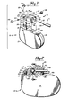
- FIG. 1 there is illustrated an exploded view of a preferred embodiment of the electrical connector of the present invention.
- Figure 1 also shows generally an implantable signal generator 10, electrical lead 11, and the preformed connector 12 of the invention which, when assembled with the other parts, constitutes a heart pacemaker.
- Signal generator 10 includes all the necessary signal generating components, in known manner, the feedthroughs having electrical connections or feedthrough pins 18 and 19.
- Feedthroughs 16 and 17 extend from a surface 20 which is adapted to receive prefonned connector 12 in a manner to be described more fully below.
- Electrical lead 11 is of the type having a pin connection 21 and insulating body 22 which surrounds and protects an electrical conductor (not shown). In use lead 11 extends from generator 10 to contact the heart muscle of the user to deliver pulses to the heart.
- Connector 12 includes a body portion 25 which may be formed in any known manner, as by molding, for example.
- body 25 is of a clear material so as to allow visual verification of the electrical connections.
- Body 25 may be formed of many known materials including, polysulfone as sold under the tradename UDEL by Union Carbide, polyurethane as sold under the trade name PELLETHANE by Upjohn, polymethylpentene as sold under the tradename TPX by Mitsui and Company, polyvinylidene fluoride as sold under the tradename KYNAR, and ethylenechlorotrifluoroethylene as sold under the tradename HALAR by the Allied Chemical Corporation.
- the undersurface 26 of body 25 is adapted to rest on surface 20 of signal generator 10 while the outer surface 27 is configured so as to extend the general outer configuration of signal generator 10 when surfaces 20 and 26 are mated.
- Many types of mechanical connections or adhesives may be used for this purpose. A typical mechanical arrangement is described herein for illustration although many other arrangements will be found to be satisfactory.
- Extending from surface 20 is a threaded stud 28 and hook member 29.
- An aperture 30 extends from the under surface 26 of body 25 and joins a second aperture 31 extending from surface 27.
- Aperture 30 is large enough to accommodate threaded stud 28 while aperture 31 is large enough to accommodate a threaded nut 33.
- the junction of the apertures 30 and 31 forms a shoulder 32 on which nut 33 rests.
- Nut 33 is provided with a slot 34 so that it may be tightened on threaded stud 28 in the known manner.
- other tools may be employed requiring a different configuration in the recess shown as slot 34.
- a hexagonal recess may be employed in conjunction with a tool of hexagonal cross section.
- a second aperture 36 extends into body 25 from its face 37.
- Aperture 26 is adapted to accept the hook portion of hook 29 while the recess 38 on the face 37 is adapted to accept the lower portion of hook 29.
- hook portion of hook 29 is inserted into recess 36 to engage its side wall and threaded stud 28 is inserted into aperture 30.
- Nut 33 then engages the threads on stud 28 and is tightened against the shoulder 32 to secure body 25 to the platform 20 and signal generator 10. This assembly is illustrated in Figure 2.
- conductive terminals 40 Contained within body 25 are conductive terminals 40, one terminal for each lead 11.
- the illustrated embodiment is intended for bi-polar stimulation. However, for the purposes of clarity, only one lead 11 and one terminal 40 are shown in Figure 1. A portion of a second lead 11 can be seen in Figure 2.
- An aperture 41 extends from face 37 of body 25 to terminal 40 with an extension 41 extending from terminal 40.
- Aperture 41 accepts lead 11 and guides pin 21 into electrical contact with terminal 40.
- an aperture 43 extends from the undersurface 26 of body 25 to terminal 40 for the purpose of accepting and guiding feedthrough pin 19 into electrical contact with terminal 40.
- Aperture 43 includes an enlarged portion 44 which accommodates feedthrough 17. Similar apertures and terminals are provided for feedthrough 16 and feedthrough pin 18.
- an aperture 45 extends from face 37 to a terminal to accommodate a second lead.
- Aperture 53 in surface 27 allowsaccess to set screws 47 carried by terminals 40 to lock pin 21 of lead 11 in position.
- Grommets 48 may be employed to seal the set screw apertures 53 while allowing access to the set screws, in known manner.
- Resilient washers 50 are provided which include a central aperture which accepts feedthrough pins 18 and 19 to rest atop feedthroughs 16 and 17. When the undersurface 26 of body 25 and surface 20 of generator 10 are mated, the shoulder formed between apertures 43 and 44 compresses the washers 50 against the top of feedthroughs 16 and 17 to seal pins 18 and 19 from the body environment.
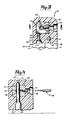
- terminal 40 includes a bore 51 which is adapted to accept pin 21 of lead 11.
- the aperture 41 of body 25 accepts lead 11 and guides pin 21 to and through bore 51.
- body 25 is made of a transparent material, as preferred, the extension of pin 21 through bore 51 and into extension 41 provides visual assurance of proper placement of pin 21 relative to terminal 40.
- a second bore 52 in terminal 40 receives pin 19 of feedthrough 17, aperture 43 accepting pin 19 and guiding it to bore 52.
- An extension 43 of aperture 43 may be provided to allow visual verification of proper positioning of pin 19 relative to the terminal 40.
- lead 11 is not positioned within aperture 41 or bore 51 so as to illustrate the intersection of the bores 51 and 52 within terminal 40, pin 19 being visible through bore 51.
- an aperture 53 is provided for access to set screw 47.
- Set screw may be provided on its end with a hexagonal recess for cooperation with a tool 54 (see Figure 4) having a similar cross section at its terminus, in known manner.
- Figure 4 is a cross section taken along line 4-4 in Figure 3 and further illustrates the intersection of bores 51 and 52, the intersection preferably being in line with the set screw. That is, as set screw 47 is tightened against pin 21, pin 21 is urged against feedthrough 19 thereby securing both pin 21 and feedthrough 19 in place within terminal 40. This further assures an electrical communication between feedthrough 19 and pin 21.
- other configurations may be employed so long as the pin 21 and feedthrough 19 are in contact with each other or with conductive terminal 40.
- aperture 43 need not guide pin 19 through a bore in terminal 40, but, instead, need only guide it into contact with that terminal 40. If pin 19 is guided to a location adjacent to terminal 40, and the material for which the body 25 is made sufficiently transparent, pin 19 and terminal 40 may be welded to each other through the body material by known techniques. Further, pin 19 may be welded within the bore 52 of Figure 4 through the aperture engaged by the set screw 47 with the set screw 47 removed. Modification to accommodate unipolar stimulation is within the skill of one ordinarily skilled in the art. Accordingly, within the scope of the appended claims, the invention may be practised other than as specifically described.
Abstract
A body implantable stimulator, e.g. a heart pacemaker comprises a signal generator (10), a preformed electrical connector (12) and at least one electrical lead (11) electrically and mechanically connected to the signal generator by preformed electrical connector (12). The connector carries at least one terminal (40) to establish electrical contact between the signal generator (10) and electric lead (11), passageways (41, 43) being provided in the connector body (25) to accept and guide the signal generator feedthrough pins (18, 19) and electrical lead (11) into contact with the terminal (40). The terminal (40) is provided with intersecting bores (51, 52) such that the respective feedthrough pins (18, 19) and electrical lead (11) form electrical contact within or by means of the terminal. The pins (18, 19) may be welded or press fit to the terminal (40) and the lead (11) may be attached to the terminal by means of a set screw (47). The preformed connector may be mechanically fastened or fastened with an adhesive to the implantable stimulator.
Description
- This invention relates to a body implantable stimulator comprising a signal generator and a lead connector secured thereto. Such body implantable stimulators are known to the prior art, the most common being the cardiac or heart pacemaker. Typically, such stimulators are formed of a separable electrical lead and a signal generator with provision being made to electrically and mechanically connect the lead anc generator to complete the stimulator unit.
- Many prior art signal generators have been formed following assembly by casting the components, including mechanical and electrical connections for the lead, in a matrix of encapsulating material, typically epoxy resin, which supports the components and shields them from the body environment.
- In the body environment, it is generally recognized that an enclosed and hermetically sealed signal generator is more reliable as a result of the known and controlled environment provided by the hermetic seal, For this reason, many recent signal generator designs include a rigid enclosure formed of a plurality of preformed members which are typically welded together to complete the enclosure. The connection between the generator and the electrical lead, when it is desired that these members be separable, occurs outside of such an enclosure. It is common to cast a connector from epoxy. However, it would be beneficial to eliminate the epoxy encapsulation process. Thus a preformed connector, which may be reliably secured to a preformed signal generator enclosure housing the generator components, would greatly facilitate assembly of the stimulator. The amount of handling would be reduced with the remaining handling being easier to perform than an epoxy casting process. One type of preformed connector assembly is disclosed in United States Patent Application Serial Number 793,642.
- The above referenced application provides a preformed connector assembly thereby eliminating the necessity of forming that assembly in place, as by an epoxy casting process, for example. Additionally, in that assembly, the electrical connection between the connector assembly terminal and the signal generator requires manipulation of a wire to position it and a weld, or other similar process, to secure it in position. Thus, while the connector assembly of the above referenced application greatly reduces the handling necessary to form and complete a connector assembly on a signal generator unit, considerably handling remains necessary.
- These shortcomings of the prior art are overcome by the invention as claimed. In one aspect, the connector is pre- formed and mechanical fastener means are provided for securing the connector to the generator. Thus, it eliminates the use of epoxy or other similar substances to encapsulate the terminal containing connector after attachment of the connector to the generator. This approach allows quality assurance of each preformed connector prior to assembly or attachment to the generator. The amount of handling necessary to assemble the stimulator and establish the proper electrical connections is reduced.
- In a preferred embodiment, the preformed connector is provided with first means, e.g. passageways which accept and guide the signal generator output connections (usually a feedthrough pin or pins) and preferably the electrical lead into electrical contact with a terminal in the connector. One or more terminals are provided with intersecting bores such that the feedthrough pin and electrical lead contact within the terminal or by means of it. Means are provided for securing the lead within the terminal. For example, this may be accomplished via a set screw which engages the lead to urge it against the terminal. The feedthrough pin may be welded-or otherwise secured to the terminal as by a press fit for example.
- In another aspect of the invention the connector comprises a preformed body formed of a moulded biocompatible material and a terminal enclosed in said body and adapted to receive and connect the output means of the generator and the lead wire,and including means attaching the connector to the generator.
- A specific embodiment of the invention is now described by way of example only with reference to the drawings in which:-
- Figure 1 is an exploded view of an embodiment of the present invention,
- Figure 2 is a partial cutaway of the embodiment of Figure 1, as assembled,
- Figure 3 is a cross section taken along the line 3-3 in Figure 2, and
- Figure 4 is a cross section taken along the line 4-4 in Figure 3.
- Referring now to Figure 1, there is illustrated an exploded view of a preferred embodiment of the electrical connector of the present invention. Figure 1 also shows generally an implantable signal generator 10, electrical lead 11, and the
preformed connector 12 of the invention which, when assembled with the other parts, constitutes a heart pacemaker. Signal generator 10 includes all the necessary signal generating components, in known manner, the feedthroughs having electrical connections orfeedthrough pins Feedthroughs surface 20 which is adapted to receive prefonnedconnector 12 in a manner to be described more fully below. Electrical lead 11 is of the type having apin connection 21 andinsulating body 22 which surrounds and protects an electrical conductor (not shown). In use lead 11 extends from generator 10 to contact the heart muscle of the user to deliver pulses to the heart. -
Connector 12 includes abody portion 25 which may be formed in any known manner, as by molding, for example. Preferably,body 25 is of a clear material so as to allow visual verification of the electrical connections.Body 25 may be formed of many known materials including, polysulfone as sold under the tradename UDEL by Union Carbide, polyurethane as sold under the trade name PELLETHANE by Upjohn, polymethylpentene as sold under the tradename TPX by Mitsui and Company, polyvinylidene fluoride as sold under the tradename KYNAR, and ethylenechlorotrifluoroethylene as sold under the tradename HALAR by the Allied Chemical Corporation. - The
undersurface 26 ofbody 25 is adapted to rest onsurface 20 of signal generator 10 while the outer surface 27 is configured so as to extend the general outer configuration of signal generator 10 whensurfaces - Extending from
surface 20 is a threadedstud 28 and hookmember 29. Anaperture 30 extends from the undersurface 26 ofbody 25 and joins asecond aperture 31 extending from surface 27.Aperture 30 is large enough to accommodate threadedstud 28 whileaperture 31 is large enough to accommodate a threadednut 33. The junction of theapertures shoulder 32 on which nut 33 rests.Nut 33 is provided with aslot 34 so that it may be tightened on threadedstud 28 in the known manner. Of course, other tools may be employed requiring a different configuration in the recess shown asslot 34. For example, a hexagonal recess may be employed in conjunction with a tool of hexagonal cross section. - A
second aperture 36 extends intobody 25 from itsface 37.Aperture 26 is adapted to accept the hook portion ofhook 29 while therecess 38 on theface 37 is adapted to accept the lower portion ofhook 29. On assembly, hook portion ofhook 29 is inserted intorecess 36 to engage its side wall and threadedstud 28 is inserted intoaperture 30.Nut 33 then engages the threads onstud 28 and is tightened against theshoulder 32 to securebody 25 to theplatform 20 and signal generator 10. This assembly is illustrated in Figure 2. - Contained within
body 25 areconductive terminals 40, one terminal for each lead 11. The illustrated embodiment is intended for bi-polar stimulation. However, for the purposes of clarity, only one lead 11 and oneterminal 40 are shown in Figure 1. A portion of a second lead 11 can be seen in Figure 2. Anaperture 41 extends fromface 37 ofbody 25 toterminal 40 with anextension 41 extending fromterminal 40.Aperture 41 accepts lead 11 and guidespin 21 into electrical contact withterminal 40. Similarly, anaperture 43 extends from theundersurface 26 ofbody 25 toterminal 40 for the purpose of accepting and guidingfeedthrough pin 19 into electrical contact withterminal 40.Aperture 43 includes an enlargedportion 44 which accommodatesfeedthrough 17. Similar apertures and terminals are provided forfeedthrough 16 andfeedthrough pin 18. For example, anaperture 45 extends fromface 37 to a terminal to accommodate a second lead.Aperture 53 in surface 27 allowsaccess to setscrews 47 carried byterminals 40 to lockpin 21 of lead 11 in position.Grommets 48 may be employed to seal theset screw apertures 53 while allowing access to the set screws, in known manner.Resilient washers 50 are provided which include a central aperture which accepts feedthrough pins 18 and 19 to rest atopfeedthroughs undersurface 26 ofbody 25 andsurface 20 of generator 10 are mated, the shoulder formed betweenapertures washers 50 against the top offeedthroughs pins - Referring now to Figure 3, there is illustrated a cross section of
body 25 taken along line 3-3 in Figure 2. As illustrated in Figure 3,terminal 40 includes abore 51 which is adapted to acceptpin 21 of lead 11. Theaperture 41 ofbody 25 accepts lead 11 and guidespin 21 to and throughbore 51. Ifbody 25 is made of a transparent material, as preferred, the extension ofpin 21 throughbore 51 and intoextension 41 provides visual assurance of proper placement ofpin 21 relative toterminal 40. Asecond bore 52 in terminal 40 (see Figure 4) receivespin 19 offeedthrough 17,aperture 43 acceptingpin 19 and guiding it to bore 52. Anextension 43 ofaperture 43 may be provided to allow visual verification of proper positioning ofpin 19 relative to the terminal 40. In the illustration of Figure 3, lead 11 is not positioned withinaperture 41 or bore 51 so as to illustrate the intersection of thebores terminal 40,pin 19 being visible throughbore 51. As described above, anaperture 53 is provided for access to setscrew 47. Set screw may be provided on its end with a hexagonal recess for cooperation with a tool 54 (see Figure 4) having a similar cross section at its terminus, in known manner. - Figure 4 is a cross section taken along line 4-4 in Figure 3 and further illustrates the intersection of
bores set screw 47 is tightened againstpin 21,pin 21 is urged againstfeedthrough 19 thereby securing bothpin 21 andfeedthrough 19 in place withinterminal 40. This further assures an electrical communication betweenfeedthrough 19 andpin 21. However, other configurations may be employed so long as thepin 21 andfeedthrough 19 are in contact with each other or withconductive terminal 40. - Obviously, many modifications and variations of the present invention are possible in light of the above teachings. As pointed out above, other securement systems may also be employed consistent with the present invention. Also,
aperture 43 need not guidepin 19 through a bore interminal 40, but, instead, need only guide it into contact with that terminal 40. Ifpin 19 is guided to a location adjacent toterminal 40, and the material for which thebody 25 is made sufficiently transparent,pin 19 and terminal 40 may be welded to each other through the body material by known techniques. Further,pin 19 may be welded within thebore 52 of Figure 4 through the aperture engaged by theset screw 47 with theset screw 47 removed. Modification to accommodate unipolar stimulation is within the skill of one ordinarily skilled in the art. Accordingly, within the scope of the appended claims, the invention may be practised other than as specifically described.
Claims (30)
1. A body implantable stimulator comprising a signal generator (10) and a lead connector (12) secured thereto, characterised in that said connector (12) is preformed and in that mechanical fastener means (28,29, 33) are provided for securing said connector (12) to said generator (10).
2. A body implantable stimulator according to claim 1 in which said mechanical fastener means (28, 29, 33) engage said connector (12) at at least two spaced locations.
3. A body implantable stimulator according to claim 1 or 2 in which said connector (12) is formed with a plurality of apertures (31, 36) and said mechanical fastener means (28, 29) extend from said signal generator (10) into said apertures (31, 36).
4. A body inplantable stimulator according to claim 4 including a member (34) threadedly engaging at least one of said fastener means (28).
5. A body implantable stimulator according to claim 3 or 4 in which one of said mechanical fastener means comprises a hook (29) engaging the sidewall of one of said apertures (36).
6. A body implantable stimulator according to any of the preceding claims in which the signal generator (10) includes output means (18, 19) extending therefrom and the connector (12) includes a plurality of terminals (40) for interconnecting said output means (18, 19) with a respective lead contact (21).
7. A body implantable stimulator according to claim 6 in which said connector (12) includes first and second bores (41, 43) for accepting and guiding said output means (18, 19) and said contacts (21) into contact with said terminals (40).
8. A body implantable stimulator according to claim 7 wherein said terminals (40) comprise first and second bores (51, 52) said first-mentioned bores (41, 43) accepting and guiding said output means (18, 19) and contacts (21) into respective terminal bores (51, 52).
9, A body implantable stimulator according to claim 8 in which said terminals-(40)further comprise means (47) for locking said output means (18, 19) and contacts (21) in respective terminal bores (51, 52).
10. A body implantable stimulator according to claim 9 in which said locking means (47) engages a respective contact (21) and urges it against a respective output means (18, 19).
11. A body implantable stimulator according to claim 9 or 10 wherein said locking means comprises a set screw (47).
12. A body implantable stimulator according to claim 9 in which said locking means comprises a weld securing said output means (18, 19) in said terminal bores (51, 52).
13. A body implantable stimulator comprising a signal generator (10) having a contact (21), and a connector (12) including a terminal (40) carried by said signal generator (10) for electrically interconnecting said output means (18, 19) with said contact (21), characterised in that said connector (12) is preformed and includes first means (43) for accepting and guiding said output means (18, 19) into contact with said terminal (40).
14. A body implantable stimulator according to claim 13 in which said terminal (40) includes a bore (52) said first means (43) guiding said output means (18, 19) into said bore (52).
15. A body implantable stimulator according to claim 13 or 14 in which said connector (12) includes second means (41) for accepting said lead (11) and guiding said contact (21) into contact with said terminal (40).
16. A body implantable stimulator according to claim 15 in which said terminal (40) includes first and second bores (51, 52) and said first and second means (43, 41) receive and guide respectively said output means (18, 19) and said lead contact (21) into said first and second bores (51, 52).
17. A body implantable stimulator according to claim 16 in which said terminal (40) further comprises means (47) for locking said output means (18, 19) and lead contact (21) in said terminal bore.
18. A body implantable stimulator according to claim 17 in which said locking means (47) engages said contact (21) and urges it against said output means (18, 19).
19. A body implantable stimulator according to claim 17 or 18 in which said locking means (47) comprises a set screw.
20. A body implantable stimulator according to claim 17 in which said locking means comprises a weld securing said output means (18, 19) in said terminal bore (51, 52).
21. A body implantable stimulator according to any of cla_ms 16 to 20 in which said first and second bores (51, 52) intersect within said terminal (40).
22. A body implantable stimulator comprising a signal generator (10) having output means (18, 19), a lead wire (11) and a pre-formed electrical connector (12) for electrically interconnecting said output means (18, 19) with said lead wire, characterised in that the connector (12) comprises a pre- formed body (25) formed of a moulded biocompatible material and a terminal (40) enclosed in said body (25) and adapted to receive and connect the output means (18, 19) and lead wire (11), and including means (28, 29, 33) attaching the connector (12) to the signal generator (10).
23. A body implantable stimulator according to claim 22 in which the connector body (25) is substantially transparent.
24. A body implantable stimulator according to claim 22 or 23 in which the connector body (25) is formed with apertures (41, 43, 45) for receiving the lead wire (11) and output means (18, 19).
25. An electrical connector for interconnecting at least one output means (18, 19) with at least one respective lead wire (11); characterised in that the connector comprises a body (25) formed of a moulded biocompatible material and including a terminal (40) enclosed in said body (25) and adapted to receive and connect the output means (18, 19) and lead wire (11).
26. An electrical connector according to claim 25 in which the moulded material is substantially transparent.
27. An electrical connector according to claim 25 or 26 in ,which the moulded material is polysulfone, polyurethane, polymethylpentene, polyvinylidene fluoride, or ethylenechlorotrifluoroethylene.
28. An electrical conductor according to claim 25, 26 or 27 in which the body (25) comprises means (41, 43) for accepting and guiding the output means (18, 19) and lead wire (11) into contact with the terminal (40).
29, An electrical conductor according to claim 28 in which the terminal (40) includes first and second intersecting bores (51,52) and said accepting and guiding means (41, 43) serves to guide the output means (18, 19) and lead wire (11) into respective said bores.
30. An electrical connector according to claim 29 in which the terminal further includes a set screw (47) for locking the lead wire (11) in its bore (51).
Applications Claiming Priority (4)
| Application Number | Priority Date | Filing Date | Title |
|---|---|---|---|
| US05/894,358 US4142532A (en) | 1978-04-07 | 1978-04-07 | Body implantable stimulator with novel connector and method |
| US894358 | 1978-04-07 | ||
| US929315 | 1978-07-31 | ||
| US05/929,315 US4226244A (en) | 1978-07-31 | 1978-07-31 | Electrical connector for implantable electrical generators |
Publications (1)
| Publication Number | Publication Date |
|---|---|
| EP0006281A1 true EP0006281A1 (en) | 1980-01-09 |
Family
ID=27129084
Family Applications (1)
| Application Number | Title | Priority Date | Filing Date |
|---|---|---|---|
| EP79300565A Withdrawn EP0006281A1 (en) | 1978-04-07 | 1979-04-05 | Body implantable stimulator and connector therefor |
Country Status (6)
| Country | Link |
|---|---|
| EP (1) | EP0006281A1 (en) |
| AR (1) | AR217363A1 (en) |
| BR (1) | BR7902152A (en) |
| DE (1) | DE2914034A1 (en) |
| ES (1) | ES479225A1 (en) |
| FR (1) | FR2422271A1 (en) |
Cited By (6)
| Publication number | Priority date | Publication date | Assignee | Title |
|---|---|---|---|---|
| FR2529087A1 (en) * | 1982-06-24 | 1983-12-30 | Telectronics Pty Ltd | CONNECTOR ASSEMBLY FOR HEART STIMULATOR ELECTRODES |
| US5755743A (en) * | 1996-06-05 | 1998-05-26 | Implex Gmbh Spezialhorgerate | Implantable unit |
| EP1230949A3 (en) * | 2001-02-08 | 2003-08-13 | Wilson Greatbatch Ltd. | One piece header assembly for an implantable medical device |
| US7167749B2 (en) | 2002-11-05 | 2007-01-23 | Wilson Greatbatch Technologies, Inc. | One piece header assembly for an implantable medical device |
| US7860568B2 (en) | 2008-04-23 | 2010-12-28 | Medtronic, Inc. | Lead retention assembly for implantable medical device |
| US8108045B2 (en) | 2007-10-29 | 2012-01-31 | Cretex Orthopaedics, Inc. | Set screw-less pacemaker header with lead lock system |
Families Citing this family (2)
| Publication number | Priority date | Publication date | Assignee | Title |
|---|---|---|---|---|
| US4860750A (en) * | 1986-04-17 | 1989-08-29 | Intermedics Inc. | Sidelock pacer lead connector |
| DE10100975C1 (en) * | 2001-01-11 | 2002-07-25 | Horst Pajunk | Clamping adapter for a catheter comprises an electrically conductive contact sleeve which proximally adjoins the clamping element and is provided with an electrical connection |
Citations (8)
| Publication number | Priority date | Publication date | Assignee | Title |
|---|---|---|---|---|
| CH327468A (en) * | 1955-03-25 | 1958-01-31 | Weber Ag Fab Elektro | Device for fastening an electrical circuit element to a rail |
| US3544955A (en) * | 1967-03-28 | 1970-12-01 | Raul Heres Ruiz | Cable connector |
| US3683933A (en) * | 1970-06-22 | 1972-08-15 | Peter B Mansfield | Implantable tissue stimulator with a porous anchoring enclosure |
| FR2268510A1 (en) * | 1974-04-26 | 1975-11-21 | Medtronic Inc | |
| US4041956A (en) * | 1976-02-17 | 1977-08-16 | Coratomic, Inc. | Pacemakers of low weight and method of making such pacemakers |
| US4072387A (en) * | 1976-02-20 | 1978-02-07 | Spectra-Strip Corporation | Multiple conductor connector unit and cable assembly |
| US4072154A (en) * | 1976-05-28 | 1978-02-07 | Cardiac Pacemakers, Inc. | Sealing arrangement for heart pacer electrode leads |
| EP0000280A1 (en) * | 1977-07-01 | 1979-01-10 | Stimtech, Inc. | Cardiac pacemakers |
-
1979
- 1979-04-03 ES ES479225A patent/ES479225A1/en not_active Expired
- 1979-04-05 EP EP79300565A patent/EP0006281A1/en not_active Withdrawn
- 1979-04-06 DE DE19792914034 patent/DE2914034A1/en not_active Withdrawn
- 1979-04-06 BR BR7902152A patent/BR7902152A/en unknown
- 1979-04-06 FR FR7908745A patent/FR2422271A1/en active Granted
- 1979-04-06 AR AR27611679A patent/AR217363A1/en active
Patent Citations (8)
| Publication number | Priority date | Publication date | Assignee | Title |
|---|---|---|---|---|
| CH327468A (en) * | 1955-03-25 | 1958-01-31 | Weber Ag Fab Elektro | Device for fastening an electrical circuit element to a rail |
| US3544955A (en) * | 1967-03-28 | 1970-12-01 | Raul Heres Ruiz | Cable connector |
| US3683933A (en) * | 1970-06-22 | 1972-08-15 | Peter B Mansfield | Implantable tissue stimulator with a porous anchoring enclosure |
| FR2268510A1 (en) * | 1974-04-26 | 1975-11-21 | Medtronic Inc | |
| US4041956A (en) * | 1976-02-17 | 1977-08-16 | Coratomic, Inc. | Pacemakers of low weight and method of making such pacemakers |
| US4072387A (en) * | 1976-02-20 | 1978-02-07 | Spectra-Strip Corporation | Multiple conductor connector unit and cable assembly |
| US4072154A (en) * | 1976-05-28 | 1978-02-07 | Cardiac Pacemakers, Inc. | Sealing arrangement for heart pacer electrode leads |
| EP0000280A1 (en) * | 1977-07-01 | 1979-01-10 | Stimtech, Inc. | Cardiac pacemakers |
Cited By (10)
| Publication number | Priority date | Publication date | Assignee | Title |
|---|---|---|---|---|
| FR2529087A1 (en) * | 1982-06-24 | 1983-12-30 | Telectronics Pty Ltd | CONNECTOR ASSEMBLY FOR HEART STIMULATOR ELECTRODES |
| US5755743A (en) * | 1996-06-05 | 1998-05-26 | Implex Gmbh Spezialhorgerate | Implantable unit |
| EP1230949A3 (en) * | 2001-02-08 | 2003-08-13 | Wilson Greatbatch Ltd. | One piece header assembly for an implantable medical device |
| EP1230948A3 (en) * | 2001-02-08 | 2003-08-13 | Wilson Greatbatch Ltd. | One piece header assembly over molded to an implantable medical device |
| US6975906B2 (en) | 2001-02-08 | 2005-12-13 | Wilson Greatbatch Ltd. | One piece header assembly over molded to an implantable medical device |
| US7069081B2 (en) | 2001-02-08 | 2006-06-27 | Wilson Greatbatch Ltd. | One piece header assembly for an implantable medical device |
| US7167749B2 (en) | 2002-11-05 | 2007-01-23 | Wilson Greatbatch Technologies, Inc. | One piece header assembly for an implantable medical device |
| US8108045B2 (en) | 2007-10-29 | 2012-01-31 | Cretex Orthopaedics, Inc. | Set screw-less pacemaker header with lead lock system |
| US9149644B2 (en) | 2007-10-29 | 2015-10-06 | Cretex Orthopaedics, Inc. | Method of manufacturing a set screw-less pacemaker header with lead lock system |
| US7860568B2 (en) | 2008-04-23 | 2010-12-28 | Medtronic, Inc. | Lead retention assembly for implantable medical device |
Also Published As
| Publication number | Publication date |
|---|---|
| FR2422271A1 (en) | 1979-11-02 |
| DE2914034A1 (en) | 1979-10-18 |
| BR7902152A (en) | 1979-12-04 |
| ES479225A1 (en) | 1979-12-01 |
| FR2422271B1 (en) | 1983-11-10 |
| AR217363A1 (en) | 1980-03-14 |
Similar Documents
| Publication | Publication Date | Title |
|---|---|---|
| US4226244A (en) | Electrical connector for implantable electrical generators | |
| US4142532A (en) | Body implantable stimulator with novel connector and method | |
| EP0004783B1 (en) | Body implantable signal generator assembly | |
| US5103818A (en) | System and method for completing electrical connections in an implantable medical device | |
| US4180078A (en) | Lead connector for a body implantable stimulator | |
| US10256590B2 (en) | Interconnect for implantable medical device header | |
| US4545381A (en) | Adapter for converting a metal encapsulated implantable cardiac pacer to an externally worn cardiac pacer | |
| US7489968B1 (en) | Pre-molded header with universal tip-to-tip feedthru adaptor | |
| US3871382A (en) | Heart stimulator system for rapid implantation and removal with improved integrity | |
| US5620476A (en) | Implantable medical device having shielded and filtered feedthrough assembly and methods for making such assembly | |
| EP1998851B1 (en) | Feedthrough connector for implantable device | |
| US6984145B1 (en) | Implantable medical device connector assembly with side-actuated lead body affixation | |
| US7195523B2 (en) | Electrical conductive path for a medical electronics device | |
| US5679026A (en) | Header adapter for an implantable cardiac stimulation device | |
| US6884122B2 (en) | Lead frame and strip molding for contact connectors in implantable medical devices | |
| US5545188A (en) | Cardiac pacemaker with collet-type lead connector | |
| US5431695A (en) | Pacemaker | |
| EP1928547B1 (en) | Implantable medical device with interweldable housing and header | |
| US5535097A (en) | Implantable medical device including a first enclosure portion having a feedthrough in a second interior surface | |
| JPH09507402A (en) | Cardiac stimulator lead wire connector | |
| US5522861A (en) | Access grommet assembly and devices using the assembly | |
| US6192277B1 (en) | Implantable device with bevel gear actuation for lead retention and actuation | |
| US4154248A (en) | Body implantable electrical stimulator | |
| EP0006281A1 (en) | Body implantable stimulator and connector therefor | |
| US6862478B1 (en) | Connector top for implantable medical device |
Legal Events
| Date | Code | Title | Description |
|---|---|---|---|
| PUAI | Public reference made under article 153(3) epc to a published international application that has entered the european phase |
Free format text: ORIGINAL CODE: 0009012 |
|
| AK | Designated contracting states |
Designated state(s): BE GB IT NL SE |
|
| 17P | Request for examination filed | ||
| ITCL | It: translation for ep claims filed |
Representative=s name: SOCIETA' ITALIANA BREVETTI S.P.A. |
|
| 18D | Application deemed to be withdrawn |
Effective date: 19830220 |
|
| RIN1 | Information on inventor provided before grant (corrected) |
Inventor name: WARE, LYLE A. Inventor name: WILARY, FRANK J. Inventor name: COURY, ARTHUR J. |