DE69925784T2 - Fuel injection pump - Google Patents
Fuel injection pump Download PDFInfo
- Publication number
- DE69925784T2 DE69925784T2 DE69925784T DE69925784T DE69925784T2 DE 69925784 T2 DE69925784 T2 DE 69925784T2 DE 69925784 T DE69925784 T DE 69925784T DE 69925784 T DE69925784 T DE 69925784T DE 69925784 T2 DE69925784 T2 DE 69925784T2
- Authority
- DE
- Germany
- Prior art keywords
- sliding
- piston
- cylinder
- surface roughness
- injection pump
- Prior art date
- Legal status (The legal status is an assumption and is not a legal conclusion. Google has not performed a legal analysis and makes no representation as to the accuracy of the status listed.)
- Expired - Lifetime
Links
Classifications
-
- F—MECHANICAL ENGINEERING; LIGHTING; HEATING; WEAPONS; BLASTING
- F04—POSITIVE - DISPLACEMENT MACHINES FOR LIQUIDS; PUMPS FOR LIQUIDS OR ELASTIC FLUIDS
- F04B—POSITIVE-DISPLACEMENT MACHINES FOR LIQUIDS; PUMPS
- F04B53/00—Component parts, details or accessories not provided for in, or of interest apart from, groups F04B1/00 - F04B23/00 or F04B39/00 - F04B47/00
- F04B53/14—Pistons, piston-rods or piston-rod connections
-
- F—MECHANICAL ENGINEERING; LIGHTING; HEATING; WEAPONS; BLASTING
- F02—COMBUSTION ENGINES; HOT-GAS OR COMBUSTION-PRODUCT ENGINE PLANTS
- F02M—SUPPLYING COMBUSTION ENGINES IN GENERAL WITH COMBUSTIBLE MIXTURES OR CONSTITUENTS THEREOF
- F02M59/00—Pumps specially adapted for fuel-injection and not provided for in groups F02M39/00 -F02M57/00, e.g. rotary cylinder-block type of pumps
- F02M59/44—Details, components parts, or accessories not provided for in, or of interest apart from, the apparatus of groups F02M59/02 - F02M59/42; Pumps having transducers, e.g. to measure displacement of pump rack or piston
- F02M59/445—Selection of particular materials
-
- F—MECHANICAL ENGINEERING; LIGHTING; HEATING; WEAPONS; BLASTING
- F04—POSITIVE - DISPLACEMENT MACHINES FOR LIQUIDS; PUMPS FOR LIQUIDS OR ELASTIC FLUIDS
- F04B—POSITIVE-DISPLACEMENT MACHINES FOR LIQUIDS; PUMPS
- F04B53/00—Component parts, details or accessories not provided for in, or of interest apart from, groups F04B1/00 - F04B23/00 or F04B39/00 - F04B47/00
- F04B53/02—Packing the free space between cylinders and pistons
-
- F—MECHANICAL ENGINEERING; LIGHTING; HEATING; WEAPONS; BLASTING
- F04—POSITIVE - DISPLACEMENT MACHINES FOR LIQUIDS; PUMPS FOR LIQUIDS OR ELASTIC FLUIDS
- F04B—POSITIVE-DISPLACEMENT MACHINES FOR LIQUIDS; PUMPS
- F04B53/00—Component parts, details or accessories not provided for in, or of interest apart from, groups F04B1/00 - F04B23/00 or F04B39/00 - F04B47/00
- F04B53/16—Casings; Cylinders; Cylinder liners or heads; Fluid connections
Description
HINTERGRUND DER ERFINDUNGBACKGROUND OF THE INVENTION
1. Gebiet der Erfindung1. Field of the invention
Diese Erfindung betrifft eine Pumpe zum Einspritzen von Benzin, Kraftstoff, dessen Hauptbestandteil Benzin ist, oder schwefelarmen Leichtöl in eine Verbrennungskammer eines Fahrzeugmotors (nachfolgend als Kraftstoffeinspritzpumpe bezeichnet oder Kraftstoff Direkteinspritzpumpe oder Direkteinspritzpumpe genannt) und spezieller die gleiche Pumpe, die verschleißfeste Keramikwerkstoffe für ihren Kolben verwendet.These The invention relates to a pump for injecting gasoline, fuel, whose main component is gasoline or low-sulfur light oil in one Combustion chamber of a vehicle engine (hereinafter referred to as fuel injection pump designated or fuel direct injection pump or direct injection pump called) and more specifically the same pump, the wear-resistant ceramic materials for her Piston used.
2. Beschreibung des Stands der Technik2. Description of the stand of the technique
In jüngster Zeit war eine Verbesserung der Kraftstoff-Wirksamkeit eines Verbrennungsmotors eines Fahrzeugs ein wichtiges Problem vom Standpunkt der Umwelt der Erde her. Aus dem Grund wurden Studien zur Verwirklichung des so genannten Motors zur Kraftstoffdirekteinspritzung im Zylinder energisch betrieben, in den Benzin oder Leichtöl direkt in eine Verbrennungskammer des gleichen Motors eingespritzt wurde. Die Kraftstoffeinspritzpumpe für die Verwendung in diesem Motor nutzt eine Hin- und Herbewegung eines Nockens, um einen ausreichenden Druck zum Einspritzen des Kraftstoffs zu erhalten. Nimmt ein Kolben (oder ein so genannter Stößel) diese Bewegung auf, gleitet er entlang einer inneren Wand des Zylinders hin und her, um so Kraftstoff in eine Verbrennungskammer einzuspritzen. Dieser Gleitzustand ist sehr hart. Daher kann durch das Verbessern der Verschleißfestigkeit und der Ermüdungs-Kennzeichen, so dass die Abnutzungsverluste verringert werden, die Leistungsfähigkeit und Lebensdauer der Kraftstoffeinspritzpumpe verbessert werden.In recently, Time was an improvement in the fuel efficiency of an internal combustion engine of a vehicle is an important problem from the standpoint of the environment the earth. For this reason, studies have been carried out to realize the so-called engine for direct fuel injection in the cylinder energetically operated, in the gasoline or light oil directly into a combustion chamber of the same engine was injected. The fuel injection pump for the Use in this engine makes use of a float Cam to a sufficient pressure to inject the fuel to obtain. Takes a piston (or a so-called plunger) this Moving on, it slides along an inner wall of the cylinder back and forth to inject fuel into a combustion chamber. This slip condition is very hard. Therefore, by improving the wear resistance and the fatigue indicator, so that the wear losses are reduced, the efficiency and life of the fuel injection pump can be improved.
Besonders der Benzin-Direkteinspritzmotor oder der Diesel-Direkteinspritzmotor eines kleinen PKW verwendet Benzin mit einer sehr niedrigen Viskosität und einer sehr hohen Verdampfungsneigung oder schwefelarmes Leichtöl mit einem niedrigen Schwefelgehalt. In einigen Motoren wird durch diese Kraftstoffe die Schmierung des Kolbens und des Zylinders erreicht. Da diese Kraftstoffe jedoch eine sehr geringe Schmierfähigkeit haben, können ungenügende Verschleißfestigkeit und ungenügendes Antiblockier-Verhalten des Kolbens und des Zylinders eine verhängnisvolle Schädigung einer Pumpe verursachen.Especially the gasoline direct injection engine or the diesel direct injection engine a small car uses gasoline with a very low viscosity and a very high high evaporation tendency or low-sulfur light oil with a low sulfur content. In some engines, these fuels will achieved lubrication of the piston and the cylinder. This one However, fuels have a very low lubricity, can be insufficient wear resistance and insufficient Anti-lock behavior of the piston and cylinder a disastrous damage cause a pump.
Als
Gegenmaßnahme
wurde üblicherweise
die Gestaltung der Gleitfläche
in verschiedenen Möglichkeiten
entworfen. Zum Beispiel wurden rostfreie Basismaterialien, deren
Korrosionsbeständigkeit
ausgezeichnet ist, als ein Material für den Kolben und den Zylinder
verwendet, wobei deren Oberfläche
so endbehandelt wird, dass sie sehr glatt ist, und um die Verschleißfestigkeit
in der Zeit des Gleitens weiter zu verbessern, wurden in der Gleitfläche des
Kolbens in einer Tiefe von maximal 2–3 μm parallele Nuten gemäß
Andererseits wurde über einer Ausführungsform des Materials zum Beispiel die offengelegte japanische Patentanmeldung Nr. 61-283 759 ein Fall offenbart, in dem SIALON oder ein keramisches Verbundmaterial aus Aluminiumoxid und Zirkoniumdioxid (Zirkoniumoxid) für eine Walze verwendet wurde, die sich direkt in einem Gleitkontakt mit einem Nocken einer Direkteinspritzpumpe eines Dieselmotors befindet. Ihre Oberfläche muss jedoch nur, wenn das gleitende Teil aus Keramik besteht, falls ein Passteil, das entsprechend gleitet, aus Metall wie Stahl hergestellt wurde, endbehandelt werden, um äußerst glatt zu sein, so dass die Aggressivität zum Passteil und ein Gleitwiderstand relativ zum Passteil nachlassen. Die offengelegte japanische Patentanmeldung Nr. 8-232 795 hat zum Beispiel einen Fall eines Dieselmotors offenbart, der schwefelarmes Leichtöl als Kraftstoff verwendet, in dem Keramik für das gleitende Teil der Direkteinspritzpumpe verwendet wurde. In der gleichen Veröffentlichung wird die Gleitfläche des gleichen Keramikwerkstoffs auf 0,5 μm oder weniger hinsichtlich der mittleren Oberflächen-Rauheit Rz oder 0,1 μm oder weniger endbehandelt. Da die keramische Gleitfläche mit einer hohen Härte gewöhnlich in eine einzelne Richtung endbehandelt wird, um gleichmäßig äußerst glatt zu sein, wie oben beschrieben wurde, benötigt es in den oben beschriebenen Fällen viel Mühe und Zeit für die Endbehandlung.On the other hand, about one embodiment of the material, for example, Japanese Patent Application Laid-Open No. 61-283759 has disclosed a case where SIALON or alumina-zirconia (zirconia) ceramic composite material was used for a roll directly in sliding contact with a cam of a direct injection pump of a diesel engine is located. However, their surface must be finished only if the sliding part is made of ceramics, if a fitting part which slides accordingly, made of metal such as steel, to be extremely smooth, so that the aggressiveness to the fitting part and a sliding resistance relative to the fitting part ease up. For example, Japanese Patent Application Laid-Open No. 8-232795 has disclosed a case of a diesel engine using low-sulfur light oil as a fuel in which ceramics have been used for the sliding part of the direct injection pump. In the same publication, the sliding surface of the same ceramic material becomes 0.5 μm or less with respect to the mean surface roughness R z or 0.1 μm or less finished. Since the ceramic sliding surface having a high hardness is usually finished in a single direction to be extremely smooth evenly as described above, it takes much trouble and time for finishing in the cases described above.
Des Weiteren wird entsprechend der offengelegten japanischen Patentanmeldung Nr. 5-340 213 ein herkömmlicher, minderwertiger Stahl als Basismaterial für das Gleitteil verwendet, wobei dann darauf ein glatter Film aus einem harten Material wie CrN, Hartkarbon (diamond like carbon – DLC) oder dergleichen auf der Gleitfläche des Basismaterials ausgebildet wird. Wenn jedoch selbst diese Materialien verwendet werden, muss die Gleitfläche endbehandelt werden, um so glatt zu sein, wie oben beschrieben wurde, wobei es zusätzlich die Befürchtung gibt, dass sich der beschichtete Film beim Gleiten lösen kann. Daher gibt es eine Möglichkeit, dass dadurch ein teilweises Blockieren verursacht werden kann. Infolgedessen gibt es ein Problem, dass eine stabilisierte Verschleißfestigkeit oder ein Antiblockierverhalten nicht erreicht werden kann.Of Further, according to the Japanese Patent Application Laid-Open No. 5-340 213 a conventional, Inferior steel used as base material for the sliding part, then a smooth film of a hard material like that CrN, hard carbon (diamond like carbon - DLC) or the like the sliding surface of the base material is formed. If, however, even these materials used, the sliding surface must be finished to to be as smooth as described above, in addition to the apprehension indicates that the coated film can be released when sliding. Therefore, there is a possibility this may cause partial blocking. Consequently There is a problem that has a stabilized wear resistance or an anti-lock behavior can not be achieved.
Zusammenfassung der ErfindungSummary the invention
Die vorliegende Erfindung wurde vom Standpunkt dieser Probleme her erbracht, wobei es daher eine Aufgabe der Erfindung ist, eine Kraftstoffeinspritzpumpe eines Fahrzeugmotors, der Benzin mit einer niedrigen Gleit-Schmierfähigkeit, Kraftstoff, dessen Hauptbestandteil Benzin ist, oder ein schwefelarmes Leichtöl verwendet, und spezieller die gleiche Pumpe, deren Verschleißfestigkeit und Antiblockier-Verhalten in der Zeit des Gleitens ausgezeichnet ist, und die zu einem niedrigen Preis geliefert werden kann, was nicht als üblich angesehen wurde, speziell eine Kombination eines Kolbens (Stößels) und Zylinders bereitzustellen.The The present invention has been accomplished from the standpoint of these problems. it is therefore an object of the invention to provide a fuel injection pump of a vehicle engine, the gasoline with a low lubricity, Fuel whose main component is gasoline or low in sulfur light oil used, and more specifically the same pump whose wear resistance and anti-skid behavior in the time of sliding excellent is, and which can be delivered at a low price, what not as usual was considered, especially a combination of a piston (plunger) and To provide cylinder.
Dementsprechend stellt die vorliegende Erfindung eine Kraftstoffeinspritzpumpe für eine Hochdruck-Einspritzung von Benzin, Kraftstoff, dessen Hauptbestandteil Benzin ist, oder Leichtöl mit einem Schwefelgehalt von 0,05% des Gewichts oder weniger durch Hin- und Herbewegen eines Kolbens bereit, der relativ zu einem Zylinder gleitet, wobei wenigstens eine Gleitfläche des Kolbens, der am Zylinder gleiten soll, aus Keramik besteht, dadurch gekennzeichnet, dass die Oberflächen-Rauheit des Keramikwerkstoffs, die als eine mittlere Oberflächen-Rauheit (Rz) ausgedrückt wird, 0,05–0,4 μm in einer Richtung rechtwinklig zur Gleitrichtung und 0,2–0,6 μm in einer Richtung parallel zur Gleitrichtung beträgt, wobei die Oberflächen-Rauheit in der Richtung rechtwinklig zur Gleitrichtung kleiner ist als die in der Richtung parallel zur Gleitrichtung, während die Oberflächen-Rauheit, die als eine mittlere Oberflächen-Rauheit (Rz) ausgedrückt wird, einer Zylinder-Gleitfläche, die das Gegenstück dazu bildet, 0,2–0,8 μm in einer Richtung parallel zur Gleitrichtung beträgt.Accordingly, the present invention provides a fuel injection pump for high-pressure injection of gasoline, fuel whose main component is gasoline, or light oil having a sulfur content of 0.05% by weight or less, by reciprocating a piston relative to a cylinder wherein at least one sliding surface of the piston to slide on the cylinder is made of ceramic, characterized in that the surface roughness of the ceramic material expressed as an average surface roughness (R z ) is 0.05-0, 4 μm in a direction perpendicular to the sliding direction and 0.2-0.6 μm in a direction parallel to the sliding direction, wherein the surface roughness in the direction perpendicular to the sliding direction is smaller than that in the direction parallel to the sliding direction, while the surfaces Roughness expressed as a mean surface roughness (R z ) of a cylinder sliding surface containing the Counterpart forms to 0.2-0.8 microns in a direction parallel to the sliding direction.
Des Weiteren hat die Pumpe den oben genannten Aufbau, in dem die Keramik ein Material, das hauptsächlich aus Siliziumnitrid oder SIALON besteht oder ein Material ist, das hauptsächlich aus Zirkoniumoxid besteht.Of Further, the pump has the above construction, in which the ceramic a material that mainly is made of silicon nitride or SIALON or is a material that mainly consists of zirconium oxide.
Kurze Beschreibung der ZeichnungenShort description the drawings
Es zeigen:It demonstrate:
Ausführliche Beschreibung der bevorzugten AusführungsbeispieleFull Description of the preferred embodiments
Die Kraftstoffeinspritzpumpe der vorliegenden Erfindung ist eine Kraftstoffeinspritzpumpe für eine Druckeinspritzung durch das Hin- und Herbewegen eines Zylinders und eines Gleitkolbens. Diese Kraftstoffeinspritzpumpe spritzt Kraftstoff mit einer niedrigen Schmierfähigkeit wie Benzin, Kraftstoff, dessen Hauptbestandteil Benzin ist, und Leichtöl mit einem Schwefelgehalt von 0,05% des Gewichts oder weniger in eine Verbrennungskammer. In einem Kolben, der auf seinem Zylinder gleitet, besteht wenigstens die Gleitfläche relativ zum Zylinder aus Keramik. Durch das Ausbilden des Kolbens aus Keramik tritt bei solch einer schwierigen Schmierungs-Bedingung ein gegenseitiges Blockieren nicht auf, wobei die Verschleißfestigkeit des Kolbens beachtlich verbessert wird.The Fuel injection pump of the present invention is a fuel injection pump for a pressure injection by moving a cylinder and a sliding piston back and forth. This fuel injection pump injects fuel with a low lubricity such as gasoline, fuel whose main ingredient is gasoline, and light oil with a sulfur content of 0.05% by weight or less in a combustion chamber. In a piston, on his cylinder slides, at least the sliding surface is made relative to the cylinder Ceramics. By forming the piston of ceramic occurs in such a difficult lubrication condition a mutual blocking not on, with the wear resistance of the piston is considerably improved.
Die Gleitfläche des Kolbens der vorliegenden Erfindung, die am Zylinder gleiten soll, hat eine Oberflächen-Rauheit, die hinsichtlich der mittleren Oberflächen-Rauheit (Rz) ausgedrückt wird, die 0,05–0,4 μm in einer Richtung rechtwinklig zur Gleitrichtung und 0,2–0,6 μm in einer Richtung parallel zur Gleitrichtung beträgt. Vorzugsweise beträgt die Oberflächen-Rauheit 0,1–0,3 μm in der Richtung rechtwinklig zur Gleitrichtung und 0,2–0,4 μm in der Richtung parallel zur Gleitrichtung. Wenn die Oberflächen-Rauheit 0,4 μm in der Richtung rechtwinklig zur Gleitrichtung oder 0,6 μm in der Richtung parallel zur Gleitrichtung überschreitet, so ist das nicht erwünscht, da die Gleitfläche des gegenüberliegenden Zylinders abgenutzt wird. Wenn andererseits die Oberflächen-Rauheit geringer ist als 0,05 μm in der Richtung rechtwinklig zur Gleitrichtung und geringer als 0,2 μm in der Richtung parallel zur Gleitrichtung des Kolbens, so ist dies nicht erwünscht, da die Aufrechterhaltung des Schmierfilms durch den Kraftstoff ungenügend ist und es mehr Arbeit und Zeit für die Bearbeitung erfordert.The sliding surface of the piston of the present invention, which is to slide on the cylinder, has a Oberflä chen-roughness that the average surface roughness (R z) is expressed as to the 0.05-0.4 micron in a direction perpendicular to the sliding direction and 0.2-0.6 microns in a direction parallel to the sliding direction is. Preferably, the surface roughness is 0.1-0.3 μm in the direction perpendicular to the sliding direction and 0.2-0.4 μm in the direction parallel to the sliding direction. When the surface roughness exceeds 0.4 μm in the direction perpendicular to the sliding direction or 0.6 μm in the direction parallel to the sliding direction, it is not desirable since the sliding surface of the opposite cylinder wears. On the other hand, if the surface roughness is less than 0.05 μm in the direction perpendicular to the sliding direction and less than 0.2 μm in the direction parallel to the sliding direction of the piston, it is undesirable because the maintenance of the lubricating film by the fuel is insufficient is and it requires more work and time for editing.
Bei der Kraftstoffeinspritzpumpe der vorliegenden Erfindung soll die Oberflächen-Rauheit, die durch die mittlere Oberflächen-Rauheit Rz ausgedrückt wird, der Gleit fläche des Zylinders, die relativ zum Kolben gleitet, 0,2–0,8 μm in der Richtung parallel zur Gleitrichtung betragen. Der Grund dafür ist, dass es, wenn die 0,8 μm überschritten werden, eine Möglichkeit gibt, dass in der Anfangsphase des Gleitens ein Blockieren mit dem Kolben auftreten kann, wobei zusätzlich die Oberfläche nicht bis auf eine Glätte von weniger als 0,2 μm mit viel Arbeit und Zeit endbehandelt werden muss. Betrachtet man das ökonomische Verhalten, so sind 0,4–0,8 μm eher vorzuziehen. Als das Material des Zylinders wird die Verwendung von rostfreiem Stahl vorgezogen, wenn man die Lebensdauer und das ökonomische Verhalten in Betracht zieht.at The fuel injection pump of the present invention is intended to Surface roughness caused by the average surface roughness Expressed in Rz will, the sliding surface of the cylinder, which slides relative to the piston, 0.2-0.8 microns in the Be direction parallel to the sliding direction. the reason for that is it when the 0.8 microns exceeded be a possibility indicates that in the initial phase of sliding a block with the Pistons may occur, in addition the surface not to a smoothness of less than 0.2 microns with a lot of work and time has to be finished. Looking at the economic Behavior, so 0.4-0.8 microns are more preferable. As the material of the cylinder becomes the use of stainless Steel is preferable, considering the lifespan and the economic Behavior is taken into account.
Die Keramikwerkstoffe für die Anwendung bei einem Kolben der vorliegenden Erfindung weisen jene mit einem thermischen Widerstand (eine Eigenschaft, dass die Oberfläche nicht beeinträchtigt wird) und einer Verschleißfestigkeit bei Temperaturen bis zu 150°C, die die höchste Nutz-Temperatur dieser Art der Pumpe ist, zum Beispiel Siliziumnitrid (Si3N4) oder SIALON, einen Verbundstoff aus SIALON und Si3N4, eine Substanz, dessen Hauptbestandteil Siliziumkarbid (SiC), Aluminiumoxid (Al2O3) oder Zirkoniumdioxid (ZrO2) ist, ein Verbundmaterial aus diesen Substanzen (zum Beispiel Si3N4 oder SIALON, in dem SiC fein verteilt ist, oder ZrO2, in dem Al2O3 fein verteilt ist) oder ein Verbundmaterial mit anderen Komponenten als diesen Substanzen (zum Beispiel Si3N4 oder SIALON, in dem TiC oder TiN fein verteilt ist), insbesondere ein Material, dessen Hauptbestandteil Siliziumnitrid (Si3N4) oder SIALON, oder ein Material, dessen Hauptbestandteil Zirkoniumdioxid (ZrO2) ist, auf.The ceramic materials for use in a piston of the present invention have those with a thermal resistance (a property that the surface is not affected) and a wear resistance at temperatures up to 150 ° C, which is the highest useful temperature of this type of pump For example, silicon nitride (Si 3 N 4 ) or SIALON, a composite of SIALON and Si 3 N 4 , a substance whose main component is silicon carbide (SiC), alumina (Al 2 O 3 ) or zirconia (ZrO 2 ) is a composite material of these substances (for example, Si 3 N 4 or SIALON in which SiC is finely divided or ZrO 2 in which Al 2 O 3 is finely divided) or a composite material having components other than these substances (for example, Si 3 N 4 or SIALON in which TiC or TiN is finely divided), in particular, a material whose main component is silicon nitride (Si 3 N 4 ) or SIALON, or a material whose main component is zirconia (ZrO 2 ) is on.
Falls das Erstgenannte als ein Kolben verwendet wird, ist er in seiner Biegefestigkeit, Härte und Verschleißfestigkeit im Vergleich mit anderen keramischen Materialien hervorragender und hat des Weiteren eine geringe Dichte und eine kleines Gewicht, so dass dessen Antriebskraft verringert werden kann. Daher ist es von diesem Standpunkt her ein vorzuziehendes Material. Speziell wenn Siliziumnitrid oder SIALON mit 80% des Gewichts oder mehr enthalten ist und die Dreipunkt-Biegefestigkeit auf der Basis von JIS R1601 wenigstens 700 MPa beträgt, ist er vom Standpunkt der Lebensdauer her gesehen am meisten vorzuziehen.If the former is used as a piston, he is in his Bending strength, hardness and wear resistance more excellent compared to other ceramic materials and further has a low density and a small weight, so that its driving force can be reduced. Therefore it is from This point of view is a preferable material. Especially if Silicon nitride or SIALON containing 80% by weight or more and the three-point bending strength based on JIS R1601 is at least 700 MPa, it is most preferable from the standpoint of durability.
Obwohl das Letztere eine geringere Härte und daher eine schwächere Verschleißfestigkeit hat, kann eine hohe Biegefestigkeit erreicht werden. Des Weiteren kann ein Material mit einem hohen Wärmeausdehnungskoeffizienten erreicht werden. Der Wärmeausdehnungskoeffizient beträgt etwa 9–11 × 10–6/°C, obwohl es von der Zusammensetzung des Zirkoniumoxids abhängt, wobei dieser im Vergleich mit anderen Keramikwerkstoffen höher ist, zum Beispiel Aluminiumoxid 6,5, Siliziumkarbid 4,7 und Siliziumnitrid 3,0 in der Einheit von × 10–6/°C. Wenn daher das gleiche Material für den Kolben verwendet wird, falls der Zylinder aus Stahl (etwa 11–12 × 10–6/°C, obwohl der Wärmeausdehnungskoeffizient vom Material abhängt) besteht, nimmt eine Differenz beim Ausdehnen und Zusammenziehen auf Grund eines Temperaturanstiegs oder -abfalls im praktischen Temperaturbereich (–50–150°C) weiter ab. Daher wird ein Abfall des Einspritzdrucks auf Grund eines Austritts zum Zeitpunkt der Druckeinspritzung des Kraftstoffs unwahrscheinlich auftreten, wobei es daher, wenn es mit einem Stahlzylinder kombiniert wird, das am meisten vorzuziehende Material als das Material des Kolbens ist. Im Fall des Kolbens der vorliegenden Erfindung kann in Betracht gezogen werden, dass seine Oberflächentemperatur örtlich auf die zuvor erwähnte obere Grenztemperatur von 150°C oder höheren Temperaturen in einem praktischen Gleitstadium ansteigt. Wo daher ein Keramikwerkstoff verwendet wird, dessen Hauptbestandteil Zirkoniumoxid ist, und das Zirkoniumoxid hauptsächlich aus der tetragonalen Phase besteht, die bei Umgebungstemperatur metastabil ist, kann in Betracht gezogen werden, dass die Kristalltransformation von der tetragonalen Phase zur monoklinen Phase durch den Wärmezyklus in der praktischen Anwendungszeit erzeugt wird, so dass die Biegefestigkeit und die Verschleißfestigkeit beeinträchtigt werden. Daher ist es vorzuziehen, Zirkoniumoxid, in dem das Verhältnis der tetragonalen Phase nicht mehr als 80% bei Beurteilung durch eine Röntgenstrahlenbeugung beträgt oder Zirkoniumoxid mit einer tetragonalen Phase zu verwenden, die so zusammengesetzt ist, dass dieser Transformationspunkt durch zunehmendes Hinzufügen einer kleinen Menge Aluminiumoxid zur Seite der hohen Temperatur hin verschoben werden kann. Obwohl Zirkoniumoxid in der kubischen Phase oder Zirkoniumoxid, das dieses enthält, in der Biegefestigkeit und der Verschleißfestigkeit schwächer ist als das zuvor erwähnte Zirkoniumoxid in der tetragonalen Phase, kann es wirksam als das Material des Kolbens der vorliegenden Erfindung verwendet werden, da das Zirkoniumoxid in der kubischen Phase bei hohen Temperaturen stabil ist und nicht die zuvor erwähnten Nachteile hat, die eine Begleiterscheinung der Kristalltransformation in der Zeit der praktischen Anwendung sind.Although the latter has a lower hardness and therefore a weaker wear resistance, high flexural strength can be achieved. Furthermore, a material having a high thermal expansion coefficient can be achieved. The coefficient of thermal expansion is about 9-11 × 10 -6 / ° C, although it depends on the composition of the zirconia, which is higher in comparison with other ceramics, for example alumina 6.5, silicon carbide 4,7 and silicon nitride 3,0 in the unit of × 10 -6 / ° C. Therefore, if the same material is used for the piston, if the cylinder is made of steel (about 11-12 × 10 -6 / ° C, although the coefficient of thermal expansion depends on the material), a difference in expansion and contraction due to a rise in temperature or -abfalls in practical temperature range (-50-150 ° C) on. Therefore, dropping the injection pressure due to leakage at the time of pressure injection of the fuel is unlikely to occur, and therefore, when combined with a steel cylinder, it is the most preferable material as the material of the piston. In the case of the piston of the present invention, it may be considered that its surface temperature locally increases to the aforementioned upper limit temperature of 150 ° C or higher in a practical sliding stage. Therefore, where a ceramic material whose main component is zirconia is used, and the zirconia mainly consists of the tetragonal phase which is metastable at ambient temperature, it can be considered that the crystal transformation from the tetragonal phase to the monoclinic phase through the heat cycle is practical Application time is generated, so that the flexural strength and the wear resistance are impaired. Therefore, it is preferable to use zirconia in which the ratio of the tetragonal phase is not more than 80% when judged by X-ray diffraction or zirconia having a tetragonal phase composed so as to increase this transformation point by increasing adding a small amount of alumina Can be moved side of the high temperature down. Although zirconia in the cubic phase or zirconium oxide containing it, in the flexural strength and the wear resistance is weaker than the aforementioned tetragonal phase zirconia, it can be effectively used as the material of the piston of the present invention because the zirconia is in the cubic phase is stable at high temperatures and does not have the aforementioned drawbacks which are a concomitant of crystal transformation at the time of practical application.
Die Gleitfläche des Kolbens der vorliegenden Erfindung, die mit dem Zylinder zusammenarbeiten soll, wird hinsichtlich der Oberflächen-Rauheit, die durch die zuvor erwähnte, mittlere Oberflächen-Rauheit Rz ausgedrückt wird, auf 0,05–0,4 μm in der Richtung rechtwinklig zur Gleitrichtung und 0,2–0,6 μm in der Richtung parallel zur Gleitrichtung endbehandelt. Als Bearbeitungsverfahren wird eine gewöhnliche, spitzenlose Schleifvorrichtung verwendet, wobei eine Feinkorn-Diamantschleifscheibe der Korngröße von mehr als #1000 verwendet wird, um die Endbearbeitung durchzuführen. Daher ist, anders als beim herkömmlichen Stahlstößel, eine Feinschleifbearbeitung in mehreren Schritten nach der Schleifbearbeitung nicht erforderlich. Damit ist es möglich, einen Kolben mit einer gewünschten Oberflächen-Rauheit bei sehr niedrigen Kosten zu erhalten.The sliding surface of the piston of the present invention intended to cooperate with the cylinder is rectangular in surface roughness expressed by the aforementioned average surface roughness R z to 0.05-0.4 μm in the direction to the sliding direction and 0.2-0.6 μm in the direction parallel to the sliding direction. As the machining method, a common tipless grinding apparatus is used, wherein a fine grain diamond grinding wheel of grain size larger than # 1000 is used to perform finishing. Therefore, unlike the conventional steel tappet, multi-step fine grinding is not required after the grinding work. This makes it possible to obtain a piston with a desired surface roughness at a very low cost.
Da die zuvor erwähnte, spitzenlose Schleifbearbeitung durchgeführt wird, ist das Bearbeitungsmuster nicht wie bei einer herkömmlichen, kreuzweise schraffierten, seichten Nut. Beim herkömmlichen Muster sind die Oberflächen-Rauheiten zwischen den Richtungen rechtwinklig und parallel zu den Gleitrichtungen im Wesentlichen gleich oder der Unterschied der Oberflächen-Rauheit zwischen diesen Richtungen ist klein, wobei aber beim Muster durch das Schleifverfahren die Oberflächen-Rauheit in der Richtung rechtwinklig zur Gleitrichtung gewöhnlich kleiner ist als die in der Richtung parallel zur Gleitrichtung.There the aforementioned, Centerless grinding is performed, the processing pattern is not as with a conventional, cross hatched, shallow groove. In the conventional Patterns are the surface roughnesses between the directions at right angles and parallel to the directions of sliding essentially the same or the difference in surface roughness between these directions is small, but in the pattern through the grinding process the surface roughness usually smaller in the direction perpendicular to the sliding direction is as in the direction parallel to the sliding direction.
Beispiel 1example 1
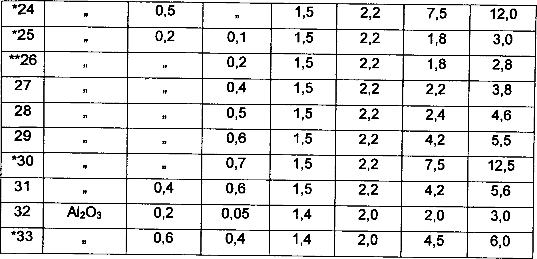
Als Material für den Kolben wurden ein vermarkteter, gesinterter Körper aus Siliziumnitrid (in Tabelle 1 als Si3N4 beschrieben) mit einer Dreipunkt-Biegefestigkeit von 850 MPa, ein vermarkteter, gesinterter Körper aus Aluminiumoxid (Tonerde) (in Tabelle 1 als Al2O3 dargestellt) mit einer Dreipunkt-Biegefestigkeit von 350 MPa und ein vermarkteter, gesinterter Körper aus Zirkoniumoxid (in Tabelle 1 als ZrO2 dargestellt) mit der Dreipunkt-Biegefestigkeit von 1100 MPa und mit 80% der tetragonalen Phase ausgewählt. Die Gleitflächen dieser Materialien wurden so endbehandelt, dass sie die Oberflächen-Rauheit gemäß Tabelle 1 sowohl in der Richtung rechtwinklig zur Gleitrichtung als auch in der Richtung parallel zur Gleitrichtung durch Kombinieren von Diamantschleifscheiben von #400–#1500 haben. In diesem Fall wurde die Endbehandlung in der Richtung rechtwinklig zur Gleitfläche des Kolbens durch das spitzenlose Schleifen durch Ändern der Körnung der Schleifscheibe erreicht. Die Endbehandlung in der Richtung parallel zur Gleitrichtung wurde durch das Ändern der Körnung der Schleifscheibe und das Bewegen des Probestücks horizontal in die axiale Richtung erreicht. Diese Endbehandlungen wurden Schritt für Schritt ausgeführt, so dass jede vorgegebene Oberflächen-Rauheit erreicht wurde.As the material for the bulb, a marketed sintered body of silicon nitride (described in Table 1 as Si 3 N 4 ) having a three-point flexural strength of 850 MPa, a marketed sintered body of alumina (alumina) (shown in Table 1 as Al 2 O 3 shown) having a three-point bending strength of 350 MPa and a marketed zirconia sintered body (shown as ZrO 2 in Table 1) having the three-point bending strength of 1100 MPa and 80% of the tetragonal phase. The sliding surfaces of these materials were finished to have the surface roughness shown in Table 1 both in the direction perpendicular to the sliding direction and in the direction parallel to the sliding direction by combining diamond grinding wheels of # 400- # 1500. In this case, the finishing treatment in the direction perpendicular to the sliding surface of the piston was achieved by the centerless grinding by changing the grit of the grinding wheel. The finishing treatment in the direction parallel to the sliding direction was achieved by changing the grit size of the grinding wheel and moving the specimen horizontally in the axial direction. These finishing operations were performed step by step so that any given surface roughness was achieved.
Bei der oben genannten Kombination des Kolbens und des Zylinders, wurde der Abnutzungsverlust und das Nichtvorhandensein oder Vorhandensein einer Blockierung des Kolbens und des Zylinders geprüft, nachdem 200 Stunden und 500 Stunden vergangen waren, seit der Vorgang gestartet wurde. Für den Kolben wurde eine Differenz des äußeren Durchmessers bestätigt, wobei für den Zylinder eine Differenz des inneren Durchmessers gemessen wurde und diese Werte in Tabelle 1 als deren Abnutzungsverlust dargestellt werden. Tabelle 2a) zeigt die Bearbeitungskosten der Probestücke Nr. 5–7, 10–12, wobei Tabelle 2b) die Bearbeitungskosten der Probestücke Nr. 20–22, 25–27 zeigt. Für a) werden sie in relativen Werten ausgedrückt, wenn das Probestück Nr. 2 als 1 angenommen wird, wobei sie für b) in relativen Werten ausgedrückt werden, wenn das Probestück Nr. 17 als 1 angenommen wird. Anhand der Ergebnisse der Tabellen 1 und 2 wird deutlich, dass durch Verwendung eines Kolbens mit dem Oberfächen-Endzustand der vorliegenden Erfindung die Verschleißfestigkeit sowohl des Kolbens als auch des Zylinders verbessert sind, deren Lebensdauer als Teile verbessert ist und die Bearbeitungskosten weitgehend verringert wurden.In the above combination of the piston and the cylinder, the wear loss became and the absence or presence of a blockage of the piston and the cylinder is checked after 200 hours and 500 hours have elapsed since the operation was started. For the piston, a difference in outer diameter was confirmed, whereby a difference in inner diameter was measured for the cylinder and these values are shown in Table 1 as its wear loss. Table 2a) shows the processing costs of the sample Nos. 5-7, 10-12, wherein Table 2b) shows the processing cost of the sample Nos. 20-22, 25-27. For a), they are expressed in relative terms when specimen No. 2 is assumed to be 1, and they are expressed in terms of relative values for specimen No. 17 when specimen No. 17 is assumed to be 1. From the results of Tables 1 and 2, it can be seen that by using a surface finished state piston of the present invention, both the wear resistance of both the piston and the cylinder are improved, the parts life is improved, and the machining costs are largely reduced.
Tabelle
1 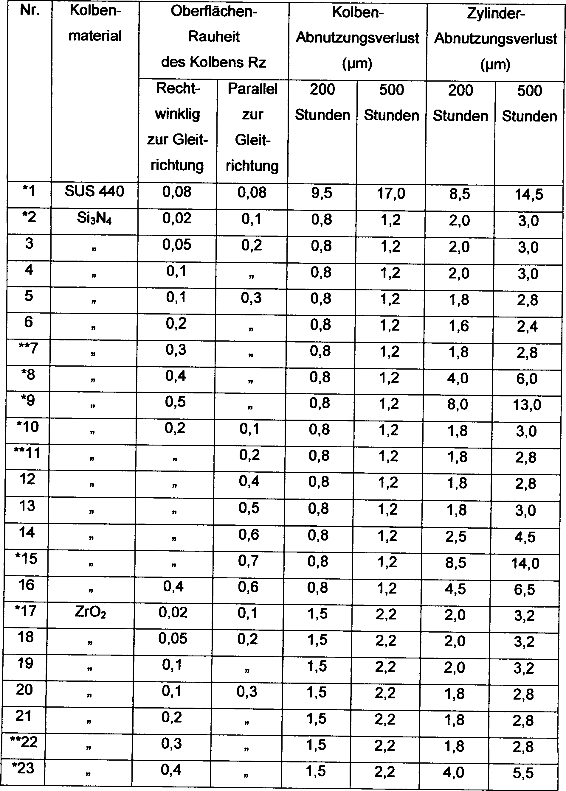
- ANMERKUNG: *kennzeichnet ein Vergleichsbeispiel.NOTE: * indicates a comparative example.
- **kennzeichnet ein Beispiel, das nicht gemäß der Erfindung ist.** denotes an example which is not according to the invention.
Tabelle
2 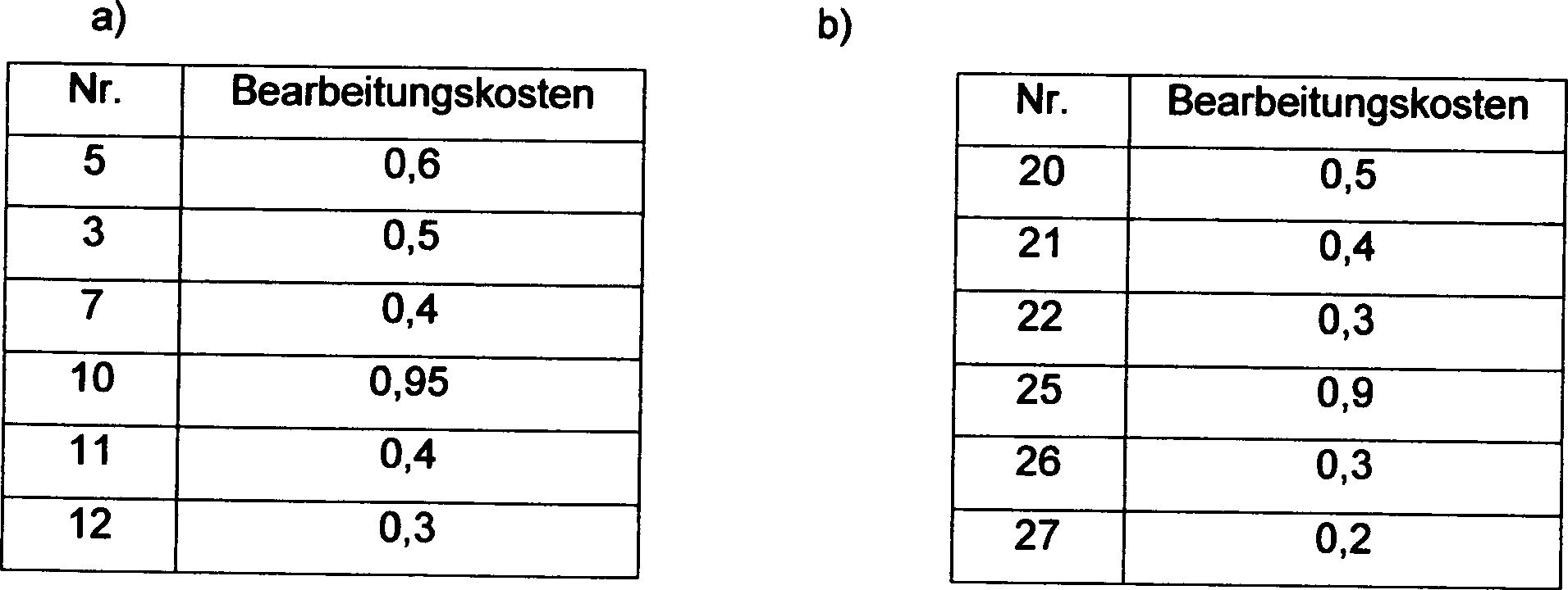
Beispiel 2Example 2
Es wurden Kolben-Probestücke der Probestücke Nr. 5 und 20 des Beispiels 1 und des Zylinders des gleichen Materials und der gleichen Form wie Beispiel 1 vorbereitet, dessen innere Gleitfläche, die am Kolben gleiten soll, nach der mittleren Oberflächen-Rauheit gemäß Tabelle 3 in der Richtung parallel zur Gleitrichtung endbehandelt wurde. Die Anfangsnummer von jeder Probestück-Nummer nach Tabelle 3 zeigt die Probestück-Nummer nach Tabelle 1 an. Mit einer Kombination gemäß Tabelle 3 wurde die gleiche Bewertung wie Beispiel 1 mittels der gleichen Testvorrichtung durchgeführt. Die Ergebnisse werden in der gleichen Tabelle gezeigt. Tabelle 4 zeigt die Bearbeitungskosten der Probestücke 5-4 – 5-6 in relativen Werten, wenn das Probestück Nr. 5-1 als 1 angenommen wird. Anhand der Ergebnisse der Tabellen 3 und 4 wird deutlich, dass bei Verwendung des Kolbens und des Zylinders mit der Oberflächen-Rauheit der vorliegenden Erfindung die Verschleißfestigkeit des Kolbens und des Zylinders verbessert ist, deren Lebensdauer als Teile verbessert ist und die Bearbeitungskosten des Zylinders weitgehend verringert sind.It were piston specimens the samples Nos. 5 and 20 of Example 1 and the cylinder of the same material and the same shape as Example 1 prepared, the inner sliding surface which should slide on the piston, after the average surface roughness according to the table 3 was finished in the direction parallel to the sliding direction. The starting number of each specimen number according to Table 3 shows the sample number according to Table 1. With a combination according to Table 3 became the same Evaluation as Example 1 performed by means of the same test device. The Results are shown in the same table. Table 4 shows the processing costs of the test pieces 5-4 - 5-6 in relative values, if the specimen No 5-1 is assumed to be 1. Based on the results of the tables 3 and 4 it becomes clear that when using the piston and the cylinder with the surface roughness the present invention, the wear resistance of the piston and improved cylinder whose life improves as parts is and greatly reduced the processing cost of the cylinder are.
Tabelle
3 
- ANMERKUNG: *kennzeichnet ein Vergleichsbeispiel.NOTE: * indicates a comparative example.
Tabelle
4 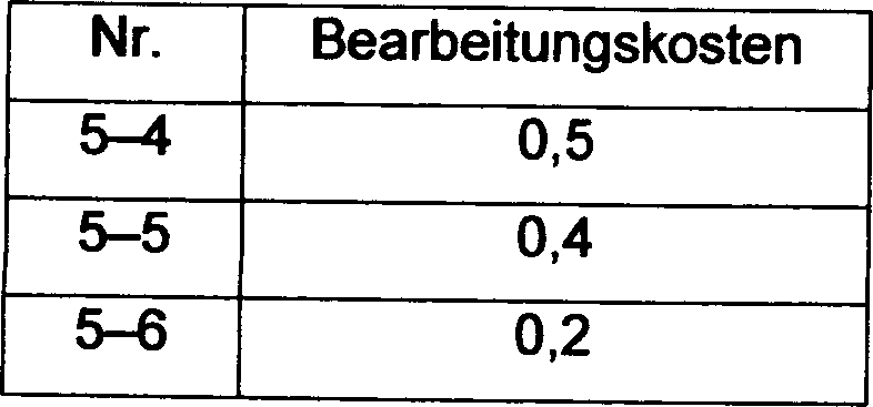
Wie oben beschrieben wird, wurde durch den Einbau der Kombination des Kolbens und des Zylinders der vorliegenden Erfindung in eine Kraftstoffeinspritzpumpe für eine Hochdruck-Einspritzung von Benzin, Kraftstoff, dessen Hauptbestandteil Benzin ist, oder schwefelarmen Leichtöl in eine Verbrennungskammer eines Fahrzeugmotors die Verschleißfestigkeit in der Zeit des Gleitens zwischen dem Kolben und dem Zylinder beachtlich verbessert, wobei die Bereitstellung einer preiswerten Kraftstoffeinspritzpumpe ermöglicht wird.As has been described above, by incorporating the combination of the Piston and the cylinder of the present invention in a fuel injection pump for one High-pressure injection of gasoline, fuel, its main component Gasoline, or low-sulfur light oil is in a combustion chamber a vehicle engine's wear resistance in the period of Sliding between the piston and the cylinder considerably improved, providing a cheap fuel injection pump allows becomes.
Claims (3)
Applications Claiming Priority (2)
| Application Number | Priority Date | Filing Date | Title |
|---|---|---|---|
| JP11450498 | 1998-04-24 | ||
| JP10114504A JPH11303709A (en) | 1998-04-24 | 1998-04-24 | Fuel injection pump |
Publications (2)
| Publication Number | Publication Date |
|---|---|
| DE69925784D1 DE69925784D1 (en) | 2005-07-21 |
| DE69925784T2 true DE69925784T2 (en) | 2006-05-18 |
Family
ID=14639419
Family Applications (1)
| Application Number | Title | Priority Date | Filing Date |
|---|---|---|---|
| DE69925784T Expired - Lifetime DE69925784T2 (en) | 1998-04-24 | 1999-04-22 | Fuel injection pump |
Country Status (4)
| Country | Link |
|---|---|
| US (1) | US6279454B1 (en) |
| EP (1) | EP0967384B1 (en) |
| JP (1) | JPH11303709A (en) |
| DE (1) | DE69925784T2 (en) |
Cited By (1)
| Publication number | Priority date | Publication date | Assignee | Title |
|---|---|---|---|---|
| DE102020215515A1 (en) | 2020-12-09 | 2022-06-09 | Robert Bosch Gesellschaft mit beschränkter Haftung | Injection plunger package for a microfluidic analysis system and method and multi-cavity injection mold for its manufacture |
Families Citing this family (12)
| Publication number | Priority date | Publication date | Assignee | Title |
|---|---|---|---|---|
| DE10032577A1 (en) * | 2000-07-05 | 2002-01-24 | Bosch Gmbh Robert | Radial piston pump |
| DE10259955A1 (en) * | 2002-12-20 | 2004-07-15 | Robert Bosch Gmbh | Fuel injection device for an internal combustion engine |
| US20050276705A1 (en) * | 2003-05-27 | 2005-12-15 | Ropintassco 2, Llc. | Positive displacement pump having piston and/or liner with vapor deposited polymer surface |
| US20040241023A1 (en) * | 2003-05-27 | 2004-12-02 | Pinkerton Harry E. | Positive displacement pump having piston and/or liner with vapor deposited polymer surface |
| JP2007092638A (en) * | 2005-09-29 | 2007-04-12 | Mitsubishi Electric Corp | Rotary compressor |
| JP2009293395A (en) * | 2008-06-02 | 2009-12-17 | Ntn Corp | Pump tappet |
| EP2402608A1 (en) * | 2010-07-02 | 2012-01-04 | Delphi Technologies Holding S.à.r.l. | Pump for dosing fluids |
| CN102691602A (en) * | 2012-05-29 | 2012-09-26 | 张昌盛 | Plunger type methanol-resistant fuel pump |
| JP6720895B2 (en) * | 2017-03-06 | 2020-07-08 | トヨタ自動車株式会社 | Fuel pump |
| US10808695B2 (en) | 2017-12-11 | 2020-10-20 | Hamilton Sundstrand Corporation | Reduction of cavitation in fuel pumps |
| KR102268258B1 (en) * | 2019-11-08 | 2021-06-23 | 엘지전자 주식회사 | Compressor and Manufacturing Method thereof |
| WO2022030431A1 (en) * | 2020-08-04 | 2022-02-10 | 京セラ株式会社 | Sliding device, plunger pump, liquid feeding device, and liquid chromatography device |
Family Cites Families (9)
| Publication number | Priority date | Publication date | Assignee | Title |
|---|---|---|---|---|
| JPS5852451A (en) * | 1981-09-24 | 1983-03-28 | Toyota Motor Corp | Heat-resistant and heat-insulating light alloy member and its manufacture |
| US4429227A (en) | 1981-12-28 | 1984-01-31 | General Electric Company | Solid state detector for CT comprising improvements in collimator plates |
| JPS61283759A (en) | 1985-06-07 | 1986-12-13 | Hitachi Metals Ltd | Ceramic parts for fuel injection pump |
| JPS62182174A (en) * | 1986-02-05 | 1987-08-10 | 日本碍子株式会社 | Ceramics-metal composite body |
| US5226975A (en) | 1991-03-20 | 1993-07-13 | Cummins Engine Company, Inc. | Plasma nitride chromium plated coating method |
| US5372115A (en) | 1991-09-10 | 1994-12-13 | Detroit Diesel Corporation | Fuel system for methanol fueled diesel cycle internal combustion engine |
| JP3148362B2 (en) | 1992-06-10 | 2001-03-19 | トヨタ自動車株式会社 | Cam contact structure of valve train |
| JP3191599B2 (en) | 1995-02-27 | 2001-07-23 | 住友電気工業株式会社 | Sliding member used for diesel engine fuel supply mechanism |
| JPH1054321A (en) * | 1996-08-08 | 1998-02-24 | Toyota Motor Corp | Roller bush for fuel injection pump |
-
1998
- 1998-04-24 JP JP10114504A patent/JPH11303709A/en active Pending
-
1999
- 1999-04-19 US US09/294,000 patent/US6279454B1/en not_active Expired - Lifetime
- 1999-04-22 EP EP99303135A patent/EP0967384B1/en not_active Expired - Lifetime
- 1999-04-22 DE DE69925784T patent/DE69925784T2/en not_active Expired - Lifetime
Cited By (1)
| Publication number | Priority date | Publication date | Assignee | Title |
|---|---|---|---|---|
| DE102020215515A1 (en) | 2020-12-09 | 2022-06-09 | Robert Bosch Gesellschaft mit beschränkter Haftung | Injection plunger package for a microfluidic analysis system and method and multi-cavity injection mold for its manufacture |
Also Published As
| Publication number | Publication date |
|---|---|
| JPH11303709A (en) | 1999-11-02 |
| EP0967384A2 (en) | 1999-12-29 |
| US6279454B1 (en) | 2001-08-28 |
| EP0967384B1 (en) | 2005-06-15 |
| DE69925784D1 (en) | 2005-07-21 |
| EP0967384A3 (en) | 2001-04-04 |
Similar Documents
| Publication | Publication Date | Title |
|---|---|---|
| DE69925784T2 (en) | Fuel injection pump | |
| DE10312227B4 (en) | Cylinder liner whose inner surface is formed with a surface-treated layer, and methods for processing the surface-treated layer | |
| DE112004002568T5 (en) | Piston for an internal combustion engine | |
| DE19825860A1 (en) | Piston ring for piston engine, with diamond-like coating | |
| EP1710216A9 (en) | Material and method for thermal coating, surface layer, as a compressor with a surface layer of the material. | |
| EP1570178B1 (en) | High pressure pump for a fuel injection device of an internal combustion engine | |
| DE4112892C2 (en) | piston ring | |
| EP1658433B1 (en) | High-pressure pump for a fuel-injection device of an internal combustion engine | |
| DE3200549A1 (en) | Internal combustion engine with improved components | |
| DE112015004758T5 (en) | PISTON RING AND COMBUSTION ENGINE | |
| EP0114655A1 (en) | Piston ring for an internal-combustion engine | |
| DE19940022C2 (en) | Piston ring combination for a diesel engine with direct injection | |
| DE102010049904A1 (en) | Cylinder head assembly for an internal combustion engine and manufacturing process | |
| DE102008001960A1 (en) | Pump i.e. fuel high-pressure pump, for fuel injecting device of internal-combustion engine, has pump housing with main housing and flange made of aluminum, that is converted into layer of alumina ceramic in area of surface at bearing areas | |
| EP2441549A2 (en) | Method for mechanical processing a waste gas conveying surface area of a combustion engine or crankcase component as well as combustion engine crankcase and cylinder liner | |
| DE19607774B4 (en) | Method for honing inner surfaces of a cylinder and cylinder | |
| DE4402090A1 (en) | Piston for internal combustion engines | |
| EP1845255A1 (en) | Fuel injector with high durability and resistance to wear | |
| DE102012101585B4 (en) | High-pressure fuel pump | |
| DE10223769A1 (en) | High pressure fuel supply apparatus | |
| EP0445292A1 (en) | Lubricating composition with a solid friction modificator | |
| EP1353061B1 (en) | Nozzle for fuel injector | |
| WO2005052356A1 (en) | Fuel-injection device for an internal combustion engine | |
| DE19851424A1 (en) | Piston ring used for I.C. engines consists of a multiphase material in the region of the ring outer surface containing finely divided hard material particles in a matrix | |
| DE102004033968B4 (en) | Use of a coating for coating heavy-duty tribological surfaces of moving components |
Legal Events
| Date | Code | Title | Description |
|---|---|---|---|
| 8364 | No opposition during term of opposition |