DE212012000041U1 - Abrasive article having a non-uniform distribution of apertures - Google Patents
Abrasive article having a non-uniform distribution of apertures Download PDFInfo
- Publication number
- DE212012000041U1 DE212012000041U1 DE212012000041U DE212012000041U DE212012000041U1 DE 212012000041 U1 DE212012000041 U1 DE 212012000041U1 DE 212012000041 U DE212012000041 U DE 212012000041U DE 212012000041 U DE212012000041 U DE 212012000041U DE 212012000041 U1 DE212012000041 U1 DE 212012000041U1
- Authority
- DE
- Germany
- Prior art keywords
- pattern
- aperture
- abrasive
- apertures
- abrasive article
- Prior art date
- Legal status (The legal status is an assumption and is not a legal conclusion. Google has not performed a legal analysis and makes no representation as to the accuracy of the status listed.)
- Expired - Lifetime
Links
Images


Classifications
-
- B—PERFORMING OPERATIONS; TRANSPORTING
- B24—GRINDING; POLISHING
- B24B—MACHINES, DEVICES, OR PROCESSES FOR GRINDING OR POLISHING; DRESSING OR CONDITIONING OF ABRADING SURFACES; FEEDING OF GRINDING, POLISHING, OR LAPPING AGENTS
- B24B55/00—Safety devices for grinding or polishing machines; Accessories fitted to grinding or polishing machines for keeping tools or parts of the machine in good working condition
- B24B55/06—Dust extraction equipment on grinding or polishing machines
- B24B55/10—Dust extraction equipment on grinding or polishing machines specially designed for portable grinding machines, e.g. hand-guided
- B24B55/102—Dust extraction equipment on grinding or polishing machines specially designed for portable grinding machines, e.g. hand-guided with rotating tools
-
- B—PERFORMING OPERATIONS; TRANSPORTING
- B24—GRINDING; POLISHING
- B24B—MACHINES, DEVICES, OR PROCESSES FOR GRINDING OR POLISHING; DRESSING OR CONDITIONING OF ABRADING SURFACES; FEEDING OF GRINDING, POLISHING, OR LAPPING AGENTS
- B24B55/00—Safety devices for grinding or polishing machines; Accessories fitted to grinding or polishing machines for keeping tools or parts of the machine in good working condition
- B24B55/06—Dust extraction equipment on grinding or polishing machines
- B24B55/10—Dust extraction equipment on grinding or polishing machines specially designed for portable grinding machines, e.g. hand-guided
- B24B55/105—Dust extraction equipment on grinding or polishing machines specially designed for portable grinding machines, e.g. hand-guided with oscillating tools
-
- B—PERFORMING OPERATIONS; TRANSPORTING
- B24—GRINDING; POLISHING
- B24B—MACHINES, DEVICES, OR PROCESSES FOR GRINDING OR POLISHING; DRESSING OR CONDITIONING OF ABRADING SURFACES; FEEDING OF GRINDING, POLISHING, OR LAPPING AGENTS
- B24B37/00—Lapping machines or devices; Accessories
- B24B37/11—Lapping tools
- B24B37/20—Lapping pads for working plane surfaces
- B24B37/26—Lapping pads for working plane surfaces characterised by the shape of the lapping pad surface, e.g. grooved
-
- B—PERFORMING OPERATIONS; TRANSPORTING
- B24—GRINDING; POLISHING
- B24B—MACHINES, DEVICES, OR PROCESSES FOR GRINDING OR POLISHING; DRESSING OR CONDITIONING OF ABRADING SURFACES; FEEDING OF GRINDING, POLISHING, OR LAPPING AGENTS
- B24B55/00—Safety devices for grinding or polishing machines; Accessories fitted to grinding or polishing machines for keeping tools or parts of the machine in good working condition
- B24B55/06—Dust extraction equipment on grinding or polishing machines
- B24B55/10—Dust extraction equipment on grinding or polishing machines specially designed for portable grinding machines, e.g. hand-guided
-
- B—PERFORMING OPERATIONS; TRANSPORTING
- B24—GRINDING; POLISHING
- B24D—TOOLS FOR GRINDING, BUFFING OR SHARPENING
- B24D11/00—Constructional features of flexible abrasive materials; Special features in the manufacture of such materials
-
- B—PERFORMING OPERATIONS; TRANSPORTING
- B24—GRINDING; POLISHING
- B24D—TOOLS FOR GRINDING, BUFFING OR SHARPENING
- B24D9/00—Wheels or drums supporting in exchangeable arrangement a layer of flexible abrasive material, e.g. sandpaper
- B24D9/08—Circular back-plates for carrying flexible material
-
- C—CHEMISTRY; METALLURGY
- C09—DYES; PAINTS; POLISHES; NATURAL RESINS; ADHESIVES; COMPOSITIONS NOT OTHERWISE PROVIDED FOR; APPLICATIONS OF MATERIALS NOT OTHERWISE PROVIDED FOR
- C09G—POLISHING COMPOSITIONS; SKI WAXES
- C09G1/00—Polishing compositions
- C09G1/02—Polishing compositions containing abrasives or grinding agents
-
- C—CHEMISTRY; METALLURGY
- C09—DYES; PAINTS; POLISHES; NATURAL RESINS; ADHESIVES; COMPOSITIONS NOT OTHERWISE PROVIDED FOR; APPLICATIONS OF MATERIALS NOT OTHERWISE PROVIDED FOR
- C09K—MATERIALS FOR MISCELLANEOUS APPLICATIONS, NOT PROVIDED FOR ELSEWHERE
- C09K3/00—Materials not provided for elsewhere
- C09K3/14—Anti-slip materials; Abrasives
- C09K3/1409—Abrasive particles per se
-
- C—CHEMISTRY; METALLURGY
- C09—DYES; PAINTS; POLISHES; NATURAL RESINS; ADHESIVES; COMPOSITIONS NOT OTHERWISE PROVIDED FOR; APPLICATIONS OF MATERIALS NOT OTHERWISE PROVIDED FOR
- C09K—MATERIALS FOR MISCELLANEOUS APPLICATIONS, NOT PROVIDED FOR ELSEWHERE
- C09K3/00—Materials not provided for elsewhere
- C09K3/14—Anti-slip materials; Abrasives
- C09K3/1436—Composite particles, e.g. coated particles
-
- B—PERFORMING OPERATIONS; TRANSPORTING
- B24—GRINDING; POLISHING
- B24D—TOOLS FOR GRINDING, BUFFING OR SHARPENING
- B24D2203/00—Tool surfaces formed with a pattern
Abstract
Schleifartikel, der Folgendes umfasst: ein beschichtetes Schleifmittel, das mehrere Aperturen aufweist, die in einem Aperturmuster angeordnet sind, wobei das Aperturmuster eine gesteuerte ungleichförmige Verteilung aufweist.An abrasive article comprising: a coated abrasive having a plurality of apertures arranged in an aperture pattern, the aperture pattern having a controlled non-uniform distribution.
Description
GEBIET DER OFFENBARUNGAREA OF REVELATION
Die vorliegende Offenbarung bezieht sich allgemein auf Schleifmittel und insbesondere auf Schleifartikel, die ein Muster von Öffnungen aufweisen, wobei das Muster ein Muster mit ungleichförmiger Verteilung ist.The present disclosure relates generally to abrasives, and more particularly to abrasive articles having a pattern of apertures, the pattern being a pattern of nonuniform distribution.
HINTERGRUNDBACKGROUND
Schleifartikel wie etwa beschichtete Schleifartikel werden in verschiedenen Branchen verwendet, um Werkstücke von Hand oder durch Maschinenprozesse wie etwa durch Läppen, Schleifen oder Polieren abzuschleifen. Die maschinelle Nutzung von Schleifartikeln erstreckt sich über einen weiten Umfang von Branchen und Verbrauchern von Optikbranchen, Kraftfahrzeuglackreparaturbranchen und Metallherstellungsbranchen bis hin zu Bau und Zimmerhandwerk. Die maschinelle Bearbeitung, etwa von Hand oder unter Verwendung üblicherweise verfügbarer Werkzeuge wie etwa Exzenterpolierer (sowohl mit zufälliger als auch mit fester Achse) und Bandschleifmaschinen und Schwingschleifmaschinen, erfolgt ebenfalls üblicherweise durch Verbraucher in Haushaltsanwendungen. In jedem dieser Beispiele werden Schleifmittel verwendet, um Oberflächenmaterial zu entfernen und um die Oberflächeneigenschaften (Planheit, Oberflächenrauigkeit, Glanz) der abgeschliffenen Oberfläche zu beeinflussen. Zusätzlich sind verschiedene Typen automatisierter Verarbeitungssysteme entwickelt worden, um Artikel mit verschiedenen Zusammensetzungen und Konfigurationen schleifend zu verarbeiten.Abrasive articles such as coated abrasive articles are used in various industries to abrade workpieces by hand or by machine processes such as lapping, grinding or polishing. The mechanized use of abrasive articles covers a wide range of industries and consumers from optical industries, automotive refinish industries, and metal manufacturing industries to construction and carpentry. Machining, such as by hand or using commonly available tools such as eccentric polishers (both random and fixed axis) and belt grinders and orbital sanders, is also commonly done by consumers in household applications. In each of these examples, abrasives are used to remove surface material and to influence the surface properties (flatness, surface roughness, gloss) of the abraded surface. In addition, various types of automated processing systems have been developed to grind articles of various compositions and configurations.
Oberflächeneigenschaften enthalten u. a. Schein, Textur, Glanz, Oberflächenrauigkeit und Gleichförmigkeit. Insbesondere werden Oberflächeneigenschaften wie etwa Rauigkeit und Glanz gemessen, um die Qualität zu bestimmen. Zum Beispiel können beim Beschichten oder Lackieren einer Oberfläche während des Auftrag- oder Trocknungsprozesses bestimmte Unvollkommenheiten oder Oberflächenschäden auftreten. Diese Oberflächenunvollkommenheiten oder Oberflächenschäden könnten Pockennarben, eine ”Orangenschalen”-Textur, ”Fischaugen” oder gekapselte Blasen- und Staubschäden enthalten. Üblicherweise werden solche Schäden in einer lackierten Oberfläche zunächst durch Schmirgeln mit einem grobkörnigen Schleifmittel, gefolgt von nachfolgendem Schmirgeln mit fortschreitend feinkörnigeren Schleifmitteln und sogar durch Hochglanzpolieren mit Woll- oder Schaumkissen, bis eine gewünschte Glattheit erzielt worden ist, entfernt. Somit beeinflussen die Eigenschaften des verwendeten Schleifartikels allgemein die Oberflächenqualität.Surface properties include u. a. Appearance, texture, gloss, surface roughness and uniformity. In particular, surface properties such as roughness and gloss are measured to determine the quality. For example, when coating or painting a surface during the application or drying process, certain imperfections or surface damage may occur. These surface imperfections or surface defects could include pockmarks, "orange peel" texture, "fish eyes", or encapsulated bladder and dust damage. Typically, such damage in a painted surface is first removed by sanding with a coarse abrasive, followed by subsequent sanding with progressively finer-grained abrasives, and even high gloss polishing with wool or foam pads until a desired smoothness has been achieved. Thus, the properties of the abrasive article used generally affect the surface quality.
Außer für die Oberflächeneigenschaften sind Branchen für die Kosten in Bezug auf Schleifoperationen sensibel. Faktoren, die die Betriebskosten beeinflussen, enthalten die Geschwindigkeit, mit der eine Oberfläche vorbereitet werden kann, und die Kosten der zum Vorbereiten dieser Oberfläche verwendeten Materialien. Typischerweise sucht die Industrie kostengünstige Materialien mit hohen Materialabtragsraten.In addition to surface properties, industries are sensitive to the cost of grinding operations. Factors that affect operating costs include the speed at which a surface can be prepared and the cost of materials used to prepare that surface. Typically, the industry seeks cost-effective materials with high material removal rates.
Allerdings zeigen Schleifmittel, die hohe Abtragsraten zeigen, häufig eine schlechte Leistung beim Erzielen erwünschter Oberflächeneigenschaften. Umgekehrt weisen Schleifmittel, die erwünschte Oberflächeneigenschaften erzeugen, häufig niedrige Materialabtragsraten auf. Aus diesem Grund ist die Vorbereitung einer Oberfläche häufig ein Mehrschrittprozess unter Verwendung verschiedener Gradationen von Schleifblättern. Typischerweise werden Oberflächenmängel (z. B. Kratzer), die durch einen Schritt eingeführt werden, unter Verwendung fortschreitend feinkörnigerer Schleifmittel in einem oder in mehreren nachfolgenden Schritten repariert (z. B. entfernt). Somit führen Schleifmittel, die Kratzer und Oberflächenmängel einführen, zu erhöhter Zeit, zu erhöhtem Aufwand und zu erhöhtem Materialverbrauch in nachfolgenden Verarbeitungsschritten und zu einer Gesamtzunahme der Gesamtverarbeitungskosten.However, abrasives that exhibit high removal rates often exhibit poor performance in achieving desirable surface properties. Conversely, abrasives that produce desirable surface properties often have low material removal rates. For this reason, the preparation of a surface is often a multi-step process using different gradations of abrasive sheets. Typically, surface defects (eg, scratches) introduced by a step are repaired (eg, removed) using progressively finer-grained abrasives in one or more subsequent steps. Thus, abrasives that introduce scratches and surface defects result in increased time, effort, and material consumption in subsequent processing steps and an overall increase in overall processing costs.
Ein zusätzlicher Faktor, der die Materialabtragsrate und die Oberflächenqualität beeinflusst, ist das ”Zusetzen” des Schleifmittels mit ”Abrieb”, d. h. mit dem Material, das von der Werkstückoberfläche abgeschliffen wird, das dazu neigt, sich an der Oberfläche der Schleifpartikel und zwischen ihnen anzusammeln. Das Zusetzen ist unerwünscht, da es typischerweise die Effektivität des Schleifprodukts verringert und sich außerdem durch Erhöhung der Wahrscheinlichkeit von Kratzschäden negativ auf die Oberflächeneigenschaften auswirken kann.An additional factor affecting the rate of material removal and surface quality is the "clogging" of the abrasive with "abrasion", i. H. with the material being ground off the workpiece surface, which tends to accumulate on the surface of the abrasive particles and between them. Clogging is undesirable because it typically reduces the effectiveness of the abrasive product and, moreover, can negatively impact surface properties by increasing the likelihood of scratch damage.
Obgleich verschiedene Bemühungen wie etwa die Einleitung von Fluiden auf die Werkstückoberfläche, um Abrieb abzuwaschen, sowie die Anwendung von Unterdrucksystemen, um Abrieb wegzuführen, während er erzeugt wird, unternommen werden, um die Ansammlung von Abrieb zu verringern, besteht weiterhin ein Bedarf an verbesserten, kostengünstigen Schleifartikeln, -prozessen und -systemen, die ein effizientes Schleifen und verbesserte Oberflächeneigenschaften fördern.While various efforts, such as the introduction of fluids onto the workpiece surface to wash off abrasion and the use of vacuum systems to remove abrasion while it is being generated, are being made to reduce the build-up of abrasion, there remains a need for improved cost-effective abrasive articles, processes, and systems that promote efficient grinding and improved surface properties.
KURZBESCHREIBUNG DER ZEICHNUNGEN BRIEF DESCRIPTION OF THE DRAWINGS
Die vorliegende Offenbarung kann besser verstanden werden und ihre zahlreichen Merkmale und Vorteile können für den Fachmann ersichtlich gemacht werden, indem auf die beigefügten Zeichnungen Bezug genommen wird.The present disclosure may be better understood and its numerous features and advantages made apparent to those skilled in the art by reference to the accompanying drawings.
Die Verwendung ähnlicher Bezugszeichen in unterschiedlichen Zeichnungen bezeichnet ähnliche oder gleiche Gegenstände. The use of similar reference numbers in different drawings indicates similar or similar items.
AUSFÜHRLICHE BESCHREIBUNGDETAILED DESCRIPTION
In einer Ausführungsform umfasst ein Schleifartikel ein beschichtetes Schleifmittel, das mehrere Löcher (im Folgenden gleichfalls als ”Durchlochungen” oder ”Aperturen” bezeichnet) aufweist, die in einem Muster angeordnet sind, das eine gesteuerte ungleichförmige Verteilung aufweist. Das Aperturmuster kann irgendein Muster, das eine gesteuerte ungleichförmige Verteilung aufweist, einschließlich eines Radialmusters, eines Spiralmusters, eines phyllotaktischen Musters, eines asymmetrischen Musters oder Kombinationen davon sein. Das Muster kann teilweise, im Wesentlichen oder vollständig asymmetrisch sein. Das Muster kann den gesamten Schleifartikel bedecken (d. h. darüber verteilt sein), kann im Wesentlichen den gesamten Schleifartikel (d. h. mehr als 50% aber weniger als 100%) bedecken, kann mehrere Teile des Schleifartikels bedecken oder kann nur einen Teil des Schleifartikels bedecken.In one embodiment, an abrasive article comprises a coated abrasive having a plurality of holes (also referred to hereafter as "perforations" or "apertures") arranged in a pattern having a controlled nonuniform distribution. The aperture pattern may be any pattern having a controlled nonuniform distribution including a radial pattern, a spiral pattern, a phyllotactic pattern, an asymmetric pattern, or combinations thereof. The pattern may be partial, substantially or completely asymmetrical. The pattern may cover (i.e., be spread over) the entire abrasive article, may substantially cover the entire abrasive article (i.e., greater than 50% but less than 100%), may cover multiple portions of the abrasive article, or may cover only a portion of the abrasive article.
Eine gesteuerte ”ungleichförmige Verteilung” bedeutet, dass das Aperturmuster eine gesteuerte Asymmetrie (d. h. eine gesteuerte Zufälligkeit) aufweist, sodass das Aperturmuster immer noch wenigstens eine teilweise bis vollständige Asymmetrie zeigt, obgleich die Verteilung von Aperturen z. B. durch eine Radialgleichung, durch eine Spiralgleichung oder durch eine phyllotaktische Gleichung beschrieben oder vorhergesagt werden kann.A controlled "non-uniform distribution" means that the aperture pattern has a controlled asymmetry (i.e., a controlled randomness) such that the aperture pattern still exhibits at least partial to complete asymmetry, although the distribution of apertures is e.g. B. by a radial equation, by a spiral equation or by a phyllotactic equation can be described or predicted.
Die gesteuerte Asymmetrie kann eine gesteuerte Reflexionsasymmetrie (auch Spiegelsymmetrie, Liniensymmetrie und Bilateralsymmetrie genannt), eine gesteuerte Rotationsasymmetrie, eine gesteuerte Translationssymmetrie, eine gesteuerte Gleitreflexionssymmetrie oder Kombinationen davon sein. Ein Beispiel einer ungleichförmigen Verteilung kann für ein radiales, spiralförmiges oder phyllotaktisches Aperturmuster demonstriert werden, das eine Rotationssymmetrie einer Ordnung eins aufweist, d. h., ein solches Aperturmuster weist keine Rotationssymmetrie auf, da sich das Aperturmuster während einer Drehung von 360° um seine Mitte nur einmal wiederholt. Mit anderen Worten, falls zwei Kopien desselben Musters direkt übereinander angeordnet werden und eine Kopie unveränderlich gehalten wird, während die zweite Kopie um 360° um ihre Mitte gedreht wird, gelangen alle Aperturen beider Kopien während der 360°-Drehung nur einmal in Ausrichtung.The controlled asymmetry may be a controlled reflection asymmetry (also called mirror symmetry, line symmetry and bilateral symmetry), a controlled rotational asymmetry, a controlled translation symmetry, a controlled sliding reflection symmetry or combinations thereof. An example of non-uniform distribution may be demonstrated for a radial, spiral, or phyllotactic aperture pattern having an order-one rotational symmetry, i. That is, such an aperture pattern has no rotational symmetry because the aperture pattern repeats only once during a 360 ° rotation about its center. In other words, if two copies of the same pattern are placed directly on top of each other and one copy is held immutable while the second copy is rotated 360 ° about its center, all the apertures of both copies only align once during the 360 ° rotation.
Typischerweise besitzen alle Aperturen eines Aperturmusters (d. h. das gesamte Muster) eine gesteuerte Asymmetrie. Allerdings wird betrachtet, dass Aperturmuster in Übereinstimmung mit den vorliegenden Ausführungsformen ebenfalls Aperturmuster enthalten, bei denen nur ein Teil der Gesamtzahl von Aperturen des Aperturmusters (d. h. ein Teil des Musters) eine gesteuerte Asymmetrie besitzt. Dies kann z. B. durch Kombinieren oder Ersetzen eines Teils eines gleichförmig verteilten Musters oder eines vollständig zufälligen Musters durch ein Muster, das eine gesteuerte ungleichförmige Verteilung aufweist, geschehen, sodass nur ein Teil der Aperturen des resultierenden Aperturmusters eine gesteuerte ungleichförmige Verteilung aufweisen. Der Teil der Gesamtaperturen, die eine gesteuerte Ungleichförmigkeit aufweisen, kann als eine diskrete Zahl oder als ein Bruchteil, Prozentsatz oder Anteil der Gesamtzahl von Aperturen des Aperturmusters quantifiziert werden. In einer Ausführungsform besitzen wenigstens 50% wenigstens 55%, wenigstens 60%, wenigstens 65%, wenigstens 70%, wenigstens 80%, wenigstens 85%, wenigstens 90%, wenigstens 95%, wenigstens 96%, wenigstens 97%, wenigstens 98%, wenigstens 99%, wenigstens 99,5%, wenigstens 99,9% der Aperturen des Aperturmusters eine gesteuerte Asymmetrie. Der Teil von Aperturen des Aperturmusters, der eine gesteuerte Asymmetrie besitzt, kann innerhalb eines Bereichs liegen, der irgendein Paar vorhergehender oberer und unterer Grenzwerte umfasst. In einer bestimmten Ausführungsform besitzen von etwa 50% bis etwa 99,9%, von etwa 60% bis etwa 99,5%, von etwa 75% bis etwa 99% des Aperturmusters eine gesteuerte ungleichförmige Verteilung.Typically, all apertures of an aperture pattern (i.e., the entire pattern) have a controlled asymmetry. However, it is contemplated that aperture patterns in accordance with the present embodiments also include aperture patterns in which only a portion of the total number of apertures of the aperture pattern (i.e., a portion of the pattern) has a controlled asymmetry. This can be z. Example, by combining or replacing a part of a uniformly distributed pattern or a completely random pattern by a pattern having a controlled non-uniform distribution, so that only a part of the apertures of the resulting aperture pattern have a controlled non-uniform distribution. The portion of the total apertures having controlled nonuniformity may be quantified as a discrete number or as a fraction, percentage or fraction of the total number of apertures of the aperture pattern. In one embodiment, at least 50% have at least 55%, at least 60%, at least 65%, at least 70%, at least 80%, at least 85%, at least 90%, at least 95%, at least 96%, at least 97%, at least 98% , at least 99%, at least 99.5%, at least 99.9% of the apertures of the aperture pattern have a controlled asymmetry. The portion of apertures of the aperture pattern having a controlled asymmetry may be within a range including any pair of previous upper and lower limits. In a particular embodiment, from about 50% to about 99.9%, from about 60% to about 99.5%, from about 75% to about 99% of the aperture pattern has a controlled non-uniform distribution.
In einer weiteren Ausführungsform besitzt das Aperturmuster eine gesteuerte Asymmetrie über wenigstens näherungsweise 5 Aperturen, über wenigstens näherungsweise 10 Aperturen, über wenigstens näherungsweise 15 Aperturen, über wenigstens näherungsweise 20 Aperturen, über wenigstens näherungsweise 25 Aperturen oder über wenigstens näherungsweise 50 Aperturen. In einer weiteren Ausführungsform besitzt das Aperturmuster eine gesteuerte Asymmetrie über nicht mehr als näherungsweise 100000 Aperturen, nicht mehr als näherungsweise 10000 Aperturen, nicht mehr als näherungsweise 5000 Aperturen, nicht mehr als näherungsweise 2500 Aperturen, nicht mehr als näherungsweise 1000 Aperturen, nicht mehr als näherungsweise 750 Aperturen oder nicht mehr als näherungsweise 500 Aperturen. Die Anzahl der Aperturen, die eine gesteuerte Asymmetrie besitzen, kann innerhalb eines Bereichs liegen, der irgendein Paar der vorhergehenden oberen und unteren Grenzwerte umfasst.In another embodiment, the aperture pattern has a controlled asymmetry over at least approximately 5 apertures, at least approximately 10 apertures, at least approximately 15 apertures, at least approximately 20 apertures, at least approximately 25 apertures, or at least approximately 50 apertures. In another embodiment, the aperture pattern has a controlled asymmetry over not more than approximately 100,000 apertures, not more than approximately 10,000 apertures, no more than approximately 5,000 apertures, no more than approximately 2,500 apertures, no more than approximately 1,000 apertures, no more than approximately 750 apertures or no more than approximately 500 apertures. The number of apertures having a controlled asymmetry may be within a range including any pair of the previous upper and lower limits.
Wie oben festgestellt wurde, kann ein Aperturmuster der vorliegenden Ausführungsform irgendein Muster, das eine gesteuerte ungleichförmige Verteilung aufweist, einschließlich eines Radialmusters, eines Spiralmusters, eines phyllotaktischen Musters, eines asymmetrischen Musters oder Kombinationen davon sein. Ein Radialmuster kann irgendein Muster, das von einem zentralen Punkt auszustrahlen scheint, wie etwa die Speichen von der Nabe eines Rads sein. As stated above, an aperture pattern of the present embodiment may be any pattern having a controlled nonuniform distribution including a radial pattern, a spiral pattern, a phyllotactic pattern, an asymmetric pattern, or combinations thereof. A radial pattern may be any pattern that appears to radiate from a central point, such as the spokes of the hub of a wheel.
In einer Ausführungsform kann ein Spiralmuster irgendeine Kurve oder Menge von Kurven sein, wobei es von einem zentralen Punkt auf dem Schleifartikel ausgeht und fortschreitend weiter verläuft, während es sich um den zentralen Punkt dreht. Der zentrale Punkt kann sich bei dem oder in der Nähe des Zentrums des Schleifartikels oder alternativ von dem Zentrum des Schleifartikels entfernt befinden. Es kann eine einzelne Spirale oder mehrere Spiralen (d. h. eine Mehrzahl von Spiralen) geben. Die Spiralen können diskret oder kontinuierlich, getrennt oder verbunden sein. Getrennte Spiralen können von verschiedenen zentralen Punkten ausgehen (d. h. jede Spirale weist ihren eigenen zentralen Punkt auf), können von einem gemeinsamen zentralen Punkt ausgehen (d. h. jede Spirale nutzt einen gemeinsamen Zentalpunkt gemeinsam) oder Kombinationen davon. Spiralmuster können enthalten: eine archimedische Spirale; eine Euler-Spirale, eine Cornu-Spirale oder Klothoide; eine Fermat-Spirale; eine hyperbolische Spirale, eine Auger-Spirale; eine logarithmische Spirale, eine Fibonacci-Spirale; eine goldene Spirale; oder Kombinationen davon.In one embodiment, a spiral pattern may be any curve or set of curves starting from a central point on the abrasive article and proceeding progressively while rotating about the central point. The central point may be at or near the center of the abrasive article, or alternatively remote from the center of the abrasive article. There may be a single spiral or multiple spirals (i.e., a plurality of spirals). The spirals may be discrete or continuous, separate or interconnected. Separate spirals can emanate from different central points (i.e., each spiral has its own central point), can emanate from a common central point (i.e., each spiral shares a common common point) or combinations thereof. Spiral patterns can contain: an Archimedean spiral; an Euler spiral, a Cornu spiral or clothoids; a Fermat spiral; a hyperbolic spiral, an Auger spiral; a logarithmic spiral, a Fibonacci spiral; a golden spiral; or combinations thereof.
In einer Ausführungsform kann das Muster ein phyllotaktisches Muster sein. Wie es hier verwendet ist, bedeutet ”ein phyllotaktisches Muster” ein Muster, das sich auf die Phyllotaxis bezieht. Die Phyllotaxis ist die Anordnung von Querorganen wie etwa Blättern, Blumen, Knospenschuppen, Blütchen und Samen in vielen Pflanzenarten. Viele phyllotaktische Muster sind durch die natürlich auftretende Erscheinung deutlich sichtbarer Muster, die Bögen, Spiralen und Wirbel aufweisen, markiert. Das Muster von Samen in dem Kopf einer Sonnenblume ist ein Beispiel dieser Erscheinung. Wie in
In einer Ausführungsform weist das Aperturmuster eine Anzahl von Spiralen in Uhrzeigerrichtung und eine Anzahl von Spiralen entgegen der Uhrzeigerrichtung auf, wobei die Anzahl der Spiralen in Uhrzeigerrichtung und die Anzahl der Spiralen entgegen der Uhrzeigerrichtung Fibonacci-Zahlen oder Vielfache von Fibonacci-Zahlen sind. In einer bestimmten Ausführungsform ist die Anzahl der Spiralen in Uhrzeigerrichtung und die Anzahl der Spiralen entgegen der Uhrzeigerrichtung als ein Paar (m, n): (3, 5), (5, 8), (8, 13), (13, 21), (21, 34), (34, 55), (55, 89), (89, 144) oder ein Vielfaches dieser Paare. In einer weiteren Ausführungsform sind die Anzahl der Spiralen in Uhrzeigerrichtung und die Anzahl der Spiralen entgegen der Uhrzeigerrichtung Lucas-Zahlen oder Vielfache von Lucas-Zahlen. In einer bestimmten Ausführungsform ist die Anzahl der Spiralen in Uhrzeigerrichtung und die Anzahl der Spiralen entgegen der Uhrzeigerrichtung als ein Paar (m, n): (3, 4), (4, 7), (7, 11), (11, 18), (18, 29), (29, 47), (47, 76) oder (76, 123) oder ein Vielfaches dieser Paare. In einer weiteren Ausführungsform sind die Anzahl der Spiralen in Uhrzeigerrichtung und die Anzahl der Spiralen entgegen der Uhrzeigerrichtung irgendwelche Zahlen in einem Verhältnis, das gegen den goldenen Schnitt konvergiert, wobei der goldene Schnitt gleich der Summe von eins plus der Quadratwurzeln aus fünf, dividiert durch zwei (1 + √5)/2, ist, was näherungsweise gleich 1,6180339887 ist. In einer bestimmten Ausführungsform ist das Verhältnis der Spiralen in Uhrzeigerrichtung und der Spiralen entgegen der Uhrzeigerrichtung näherungsweise gleich dem goldenen Schnitt.In one embodiment, the aperture pattern comprises a number of clockwise spirals and a number of counterclockwise spirals, wherein the number of clockwise spirals and the number of counterclockwise spirals are Fibonacci numbers or multiples of Fibonacci numbers. In a particular embodiment, the number of clockwise spirals and the number of counterclockwise spirals are as a pair (m, n): (3, 5), (5, 8), (8, 13), (13, 21 ), (21, 34), (34, 55), (55, 89), (89, 144) or a multiple of these pairs. In another embodiment, the number of clockwise spirals and the number of counterclockwise spirals are Lucas numbers or multiples of Lucas numbers. In a particular embodiment, the number of clockwise spirals and the number of counterclockwise spirals are as a pair (m, n): (3, 4), (4, 7), (7, 11), (11, 18 ), (18, 29), (29, 47), (47, 76) or (76, 123) or a multiple of these pairs. In another embodiment, the number of clockwise spirals and the number of counterclockwise spirals are any numbers in a ratio that converges to the golden ratio, the golden ratio being equal to the sum of one plus the square roots of five divided by two (1 + √5) / 2, which is approximately equal to 1.6180339887. In a particular embodiment, the ratio of the clockwise spirals and the counterclockwise spirals is approximately equal to the golden ratio.
Wie bereits oben erwähnt wurde, ist in der Natur beobachtet worden, dass die Samen der Sonnenblumenpflanze in einem spiralförmigen phyllotaktischen Muster angeordnet sind. In einer Ausführungsform ist das Aperturmuster ein Sonnenblumenmuster.As already mentioned above, it has been observed in nature that the seeds of the sunflower plant are arranged in a spiral phyllotactic pattern. In one embodiment, the aperture pattern is a sunflower pattern.
Das Sonnenblumenmuster wird durch das Vogel-Modell beschrieben, das ein Typ einer ”Fibonacci-Spirale” oder einer Spirale, in der der Divergenzwinkel zwischen aufeinanderfolgenden Punkten ein festgelegter Fibonacci-Winkel, der sich dem goldenen Winkel annähert, der gleich 137,508° ist, ist.The sunflower pattern is described by the Vogel model, which is a type of "Fibonacci spiral" or spiral in which the divergence angle between successive points is a fixed Fibonacci angle approaching the golden angle equal to 137.508 ° ,
n die Ordnungszahl einer Einzelblüte, vom Zentrum nach außen gezählt, ist;
φ der Winkel zwischen einer Referenzrichtung und dem Ortsvektor der n-ten Einzelblüte in einem Polarkoordinatensystem mit dem Ursprung im Zentrum des Capitulums ist, sodass der Divergenzwinkel α zwischen den Ortsvektoren zweier beliebiger aufeinanderfolgender Einzelblüten konstant ist und in Bezug auf das Sonnenblumenmuster bei 137,508° liegt;
r die Entfernung vom Zentrum des Capitulums und vom Zentrum der n-ten Einzelblüte ist; und
c ein konstanter Skalierungsfaktor ist.
n is the atomic number of a single flower, counted outwards from the center;
φ is the angle between a reference direction and the location vector of the nth single flower in a polar coordinate system with the origin in the center of the capitulum such that the divergence angle α between the position vectors of any two successive individual flowers is constant and is 137.508 ° with respect to the sunflower pattern;
r is the distance from the center of the capitulum and from the center of the nth single flower; and
c is a constant scaling factor.
In einer Ausführungsform wird das Aperturmuster durch das Vogel-Modell oder durch eine Abwandlung des Vogel-Modells beschrieben. In einer bestimmten Ausführungsform wird das Aperturmuster durch das Vogel-Modell beschrieben, wobei:
n die Ordnungszahl einer Apertur, vom Zentrum des Aperturmusters nach außen gezählt, ist;
φ der Winkel zwischen einer Referenzrichtung und einem Ortsvektor der n-ten Apertur in einem Polarkoordinatensystem mit dem Ursprung im Zentrum des Aperturmusters ist, sodass der Divergenzwinkel zwischen den Ortsvektoren zweier beliebiger aufeinanderfolgender Aperturen ein konstanter Winkel α ist;
r die Entfernung vom Zentrum des Aperturmusters bis zum Zentrum der n-ten Apertur ist; und
c ein konstanter Skalierungsfaktor ist.In one embodiment, the aperture pattern is described by the bird model or by a variation of the bird model. In a particular embodiment, the aperture pattern is described by the Vogel model, where:
n is the ordinal number of an aperture, outwardly of the center of the aperture pattern;
φ is the angle between a reference direction and a location vector of the nth aperture in a polar coordinate system having the origin at the center of the aperture pattern such that the divergence angle between the position vectors of any two successive apertures is a constant angle α;
r is the distance from the center of the aperture pattern to the center of the nth aperture; and
c is a constant scaling factor.
Wie oben festgestellt wurde, sind alle, im Wesentlichen alle oder ein Teil der Aperturen des Aperturmusters durch das Vogel-Modell beschrieben (d. h. stehen sie in Übereinstimmung mit diesem). In einer Ausführungsform sind alle Aperturen des Aperturmusters durch das Vogel-Modell beschrieben. In einer weiteren Ausführungsform sind wenigstens 50%, wenigstens 60%, wenigstens 70%, wenigstens 80%, wenigstens 90%, wenigstens 95%, wenigstens 99% der Aperturen durch das Vogel-Modell beschrieben.As stated above, all, substantially all or part of the apertures of the aperture pattern are described (i.e., in accordance with) the Vogel model. In one embodiment, all apertures of the aperture pattern are described by the Vogel model. In another embodiment, at least 50%, at least 60%, at least 70%, at least 80%, at least 90%, at least 95%, at least 99% of the apertures are described by the Vogel model.
Die Erfinder haben ermittelt, dass phyllotaktische Muster bei der Erzeugung neuer Aperturmuster, die die Leistung von Schleifartikeln einschließlich befestigter Schleifartikel wie etwa gebundener Schleifartikel und beschichteter Schleifartikel verbessern, nutzbar sind. Insbesondere sind phyllotaktische Muster beim Erzeugen neuer Aperturmuster für beschichtete Schleifartikel nutzbar. Phyllotaktische Aperturmuster helfen, die konkurrierenden Probleme, eine hohe Abtragsrate von Oberflächenmaterial zu erzielen, während weiter eine akzeptable Oberflächenqualität erzielt wird, die Menge des Abriebs, der die Schleiffläche zusetzt, zu verringern und eine hohe Haltbarkeit und lange Lebensdauer des Schleifmittels aufrechtzuerhalten, zu lösen. Dies ist wenigstens in folgender Hinsicht neuartig. Zunächst stellen die phyllotaktischen Aperturmuster der vorliegenden Ausführungsformen neuartig eine überlegene Abriebabtransportabdeckung sicher und weisen im Vergleich zu Schleifmittel-Aperturmustern des Standes der Technik selbst dann eine vollständigere Verteilung der Abriebabtransportstellen (d. h. Aperturen) über die Fläche des Schleifmittels auf, wenn sie eine Gesamtaperturfläche aufweisen, die kleiner als die Gesamtaperturfläche eines Aperturmusters des Standes der Technik ist. Zweitens stellen phyllotaktische Aperturmuster der vorliegenden Ausführungsformen im Vergleich zu Aperturmustern des Standes der Technik mit oder ohne Anwendung von Unterdruck selbst dann, wenn die Gesamtschleiffläche kleiner als die von Aperturmustern des Standes der Technik ist, neuartig wenigstens eine vergleichbare bis überlegene Schleifleistung (z. B. kumulative Materialzerspanung) sicher. Drittens können phyllotaktische Muster der vorliegenden Ausführungsformen im Vergleich zu Aperturmustern des Standes der Technik neuartig eine erhöhte Schleiffläche sicherstellen, auch wenn weiterhin eine Aperturbedeckung bereitgestellt wird, die vollständiger als die von Aperturmustern des Standes der Technik ist. Wie in der Anmeldung ausführlicher diskutiert ist, können außerdem die Effektivität und die Leistung der vorliegenden Ausführungsformen noch weiter verbessert werden, wenn sie mit einem zusammenwirkenden Schleifteller und Unterdrucksystem gepaart werden.The inventors have determined that phyllotactic patterns are useful in creating new aperture patterns that enhance the performance of abrasive articles including attached abrasive articles such as bonded abrasive articles and coated abrasive articles. In particular, phyllotactic patterns are useful in creating new aperture patterns for coated abrasive articles. Phyllotactic aperture patterns help solve the competing problems of achieving a high surface material removal rate while still achieving acceptable surface quality, reducing the amount of abrasion that adds to the abrasive surface, and maintaining high durability and long life of the abrasive. This is at least novel in the following ways. First, the phyllotactic aperture patterns of the present embodiments provide novel superior abrasion removal coverage and, compared to prior art abrasive aperture patterns, exhibit a more complete distribution of the abrasion removal sites (ie, apertures) across the surface of the abrasive, even if they have a total aperture area is smaller than the total aperture area of an aperture pattern of the prior art. Second, phyllotactic aperture patterns of the present embodiments, when compared to prior art aperture patterns, with or without application of negative pressure, even when the total grinding surface area is smaller than that of prior art aperture patterns, newly provide at least comparable to superior grinding performance (e.g. cumulative Materialzerspanung) sure. Third, phyllotactic patterns of the present embodiments can, in comparison to prior art aperture patterns, genuinely ensure an increased abrasive surface, while still providing an aperture coverage more complete than that of prior art aperture patterns. In addition, as discussed in more detail in the application, the effectiveness and performance of the present embodiments can be further enhanced when paired with a cooperating pad and vacuum system.
Es wird gewürdigt werden, dass wichtige Aspekte des Aperturmusterentwurfs für beschichtete Schleifartikel den Prozentsatz des Gesamtschleifmittelflächeninhalts, den Prozentsatz der Gesamtfläche, der den Aperturen gewidmet ist (d. h. die Aperturfläche); das Verhältnis des Schleifmittelflächeninhalts zur Aperturfläche, die vorhergesagte Aperturflächenbedeckung, während der Schleifartikel in Verwendung ist (z. B. die Rotation in einem Exzenterpolierer, die Schwingung in einem Schwingschleifer, die kontinuierliche Querbewegung in einer Bandschleifmaschine), den Skalierungsfaktor, die Anzahl der Aperturen, den Divergenzwinkel zwischen den Aperturen, die Größe der Aperturen, die Entfernung zwischen benachbarten Aperturen und die Entfernung zwischen den äußersten Aperturen und dem Rand oder den Rändern des beschichteten Schleifartikels enthalten.It will be appreciated that important aspects of the aperture pattern design for coated abrasive articles include the percentage of total abrasive surface area, the percentage of total area devoted to the apertures (ie, the aperture area); the ratio of the abrasive surface area to the aperture area, the predicted aperture area coverage while the abrasive article is in use (e.g., rotation in an eccentric polisher, vibration in an orbital sander, continuous transverse motion in a belt sander), the scale factor, the number of apertures, the divergence angle between the apertures, the size of the apertures, the distance between adjacent apertures, and the Distance between the outermost apertures and the edge or edges of the coated abrasive article included.
Größen von SchleifscheibenSizes of grinding wheels
Es gibt verschiedene Größen von Schleifmitteln, die in der Industrie und von kommerziellen Verbrauchern häufig verwendet werden, deren Durchmesser typischerweise in einem Bereich von etwa Bruchteilen eines Zolls bis zu einem Durchmesser von mehreren Fuß liegt. Die vorliegenden Aperturmuster sind zur Verwendung an Schleifmitteln mit fast allen Größen einschließlich verschiedener Normgrößen von Schleifscheiben (z. B. 3 Zoll bis 20 Zoll) geeignet. In einer Ausführungsform ist der Schleifartikel eine Kreisscheibe, die einen Durchmesser von wenigstens etwa 0,25 Zoll, wenigstens etwa 0,5 Zoll, wenigstens etwa 1,0 Zoll, wenigstens etwa 1,5 Zoll, wenigstens etwa 2,0 Zoll, wenigstens etwa 2,5 Zoll oder wenigstens 3,0 Zoll aufweist. In einer weiteren Ausführungsform ist der Schleifartikel eine Kreisscheibe, die einen Durchmesser von nicht mehr als etwa 72 Zoll, von nicht mehr als etwa 60 Zoll, von nicht mehr als etwa 48 Zoll, von nicht mehr als etwa 36 Zoll, von nicht mehr als etwa 24 Zoll, von nicht mehr als etwa 20 Zoll, von nicht mehr als etwa 18 Zoll, von nicht mehr als etwa 12 Zoll, von nicht mehr als etwa 10 Zoll, von nicht mehr als etwa 9 Zoll, von nicht mehr als etwa 8 Zoll, von nicht mehr als etwa 7 Zoll oder von nicht mehr als etwa 6 Zoll aufweist. In einer weiteren Ausführungsform weist der Schleifartikel eine Größe von einem Durchmesser in dem Bereich von etwa 0,5 Zoll bis zu einem Durchmesser von etwa 48 Zoll, von einem Durchmesser von etwa 1,0 Zoll bis zu einem Durchmesser von etwa 20 Zoll, von einen Durchmesser von etwa 1,5 Zoll bis zu einem Durchmesser von etwa 12 Zoll auf.There are various sizes of abrasives that are commonly used in the industry and by commercial consumers, whose diameter typically ranges from about fractions of an inch to a diameter of several feet. The present aperture patterns are suitable for use on abrasives of almost any size, including various standard sizes of abrasive wheels (e.g., 3 inches to 20 inches). In one embodiment, the abrasive article is a circular disc having a diameter of at least about 0.25 inches, at least about 0.5 inches, at least about 1.0 inches, at least about 1.5 inches, at least about 2.0 inches, at least about 2.5 inches or at least 3.0 inches. In another embodiment, the abrasive article is a circular disk having a diameter of not more than about 72 inches, not more than about 60 inches, not more than about 48 inches, not more than about 36 inches, not more than about 24 inches, not more than about 20 inches, not more than about 18 inches, not more than about 12 inches, not more than about 10 inches, not more than about 9 inches, not more than about 8 inches of not more than about 7 inches or not more than about 6 inches. In another embodiment, the abrasive article has a diameter ranging from about 0.5 inches in diameter to about 48 inches in diameter, from about 1.0 inch in diameter to about 20 inches in diameter Diameter of about 1.5 inches to a diameter of about 12 inches.
Potentieller GesamtflächeninhaltTotal potential area
Die Größe und die Form des Schleifartikels bestimmen den potentiellen Gesamtflächeninhalt des Schleifartikels. Zum Beispiel weist eine Schleifscheibe, die einen Durchmesser von 1 Zoll aufweist, einen potentiellen Gesamtflächeninhalt von 0,7854 Zoll2 auf. Als ein weiteres Beispiel hätte ein rechteckiges Schleifblatt, das 2 Zoll mal 3 Zoll misst, einen potentiellen Gesamtflächeninhalt von 6 Zoll2.The size and shape of the abrasive article determine the potential total surface area of the abrasive article. For example, a 1 inch diameter abrasive wheel has a potential total surface area of 0.7854 in 2 . As another example, a rectangular abrasive sheet measuring 2 inches by 3 inches would have a potential total surface area of 6 inches 2 .
GesamtaperturflächeGesamtaperturfläche
Die Gesamtaperturfläche beeinflusst die Menge der Abriebextraktion. Typischerweise nimmt die Menge der Abriebextraktion zu, während die Menge der Aperturfläche zunimmt, was dazu neigt, die Materialabtragsrate (d. h. die ”Zerspanungsrate”) des Schleifartikels während der Nutzung aufrechtzuerhalten oder gelegentlich zu verbessern. Allerdings verringert die Erhöhung der Menge der Aperturfläche ebenfalls direkt die Menge der verfügbaren Schleiffläche, was an einem bestimmten Punkt die Materialabtragrate verringern wird. In einer Ausführungsform ist die Gesamtaperturfläche gleich der Summe der Fläche aller Aperturen auf der Fläche des Schleifartikels. In einer Ausführungsform beträgt die Gesamtaperturfläche höchstens etwa 0,5% des potentiellen Gesamtflächeninhalts für den Schleifartikel, wenigstens etwa 0,75%, wenigstens etwa 1,0%, wenigstens etwa 1,25%, wenigstens etwa 1,5%, wenigstens etwa 1,75%, wenigstens etwa 2,0%, wenigstens etwa 2,25%, wenigstens etwa 2,5% oder wenigstens etwa 3,0%. In einer weiteren Ausführungsform ist die Gesamtaperturfläche nicht größer als etwa 50%, nicht größer als etwa 45%, nicht größer als etwa 40%, nicht größer als etwa 35%, nicht größer als etwa 30%, nicht größer als etwa 25%, nicht größer als etwa 20%, nicht größer als etwa 15% oder nicht größer als etwa 12%. Die Menge der Gesamtaperturfläche kann innerhalb eines Bereichs liegen, der irgendein Paar vorhergehender oberer und unterer Grenzwerte umfasst. In einer weiteren Ausführungsform liegt die Gesamtaperturfläche im Bereich von etwa 0,5% bis etwa 35%, von etwa 1,0% bis etwa 25%, von etwa 1,5% bis etwa 15% oder von etwa 2,0% bis etwa 10%. In einer bestimmten Ausführungsform liegt die Menge der Gesamtaperturfläche in dem Bereich von etwa 2,5% bis etwa 10%. Die Gesamtapertur kann als eine diskrete Menge anstelle eines Prozentsatzes angesehen werden. Zum Beispiel kann eine Fünf-Zoll-Schleifscheibe eine Gesamtaperturfläche in dem Bereich von etwa 0,0982 Zoll2 bis etwa 9,8175 Zoll2 aufweisen.The total aperture area affects the amount of abrasion extraction. Typically, the amount of abrasion extraction increases as the amount of aperture area increases, tending to maintain or, occasionally, improve the rate of material removal (ie, "chipping rate") of the abrasive article during use. However, increasing the amount of aperture area also directly reduces the amount of abrasive surface available, which at some point will decrease the material removal rate. In one embodiment, the total aperture area is equal to the sum of the area of all apertures on the surface of the abrasive article. In one embodiment, the total aperture area is at most about 0.5% of the total potential surface area for the abrasive article, at least about 0.75%, at least about 1.0%, at least about 1.25%, at least about 1.5%, at least about 1 , 75%, at least about 2.0%, at least about 2.25%, at least about 2.5%, or at least about 3.0%. In another embodiment, the total aperture area is not greater than about 50%, not greater than about 45%, not greater than about 40%, not greater than about 35%, not greater than about 30%, not greater than about 25% greater than about 20%, not greater than about 15% or not greater than about 12%. The amount of total aperture area may be within a range including any pair of previous upper and lower limits. In another embodiment, the total aperture area is in the range of about 0.5% to about 35%, from about 1.0% to about 25%, from about 1.5% to about 15%, or from about 2.0% to about 10%. In one particular embodiment, the amount of total aperture area is in the range of about 2.5% to about 10%. The total aperture can be considered as a discrete set rather than a percentage. For example, a five inch abrasive wheel may have a total aperture area in the range of about 0.0982 in. 2 to about 9.8175 in. 2 .
GesamtschleifmittelflächeninhaltTotal abrasive surface area
Der Gesamtschleifmittelflächeninhalt beeinflusst die Menge des entfernten Oberflächenmaterials. Typischerweise wird die Menge des entfernten Oberflächenmaterials erhöht, während die Menge des Gesamtschleifmittelflächeninhalts erhöht wird. Außerdem wird typischerweise sowohl die Tendenz, dass sich Abrieb ansammelt, erhöht als auch die Neigung der Oberflächenrauigkeit, sich zu erhöhen, erhöht, während die Menge des entfernten Oberflächenmaterials erhöht wird. In einer Ausführungsform ist der Gesamtschleifmittelflächeninhalt des beschichteten Schleifmittels gleich der potentiellen Gesamtoberfläche des Schleifartikels (d. h. gleich dem Schleifmittelflächeninhalt, falls es keine Öffnungen gibt), minus der Gesamtaperturfläche (d. h. der Summe der Fläche aller Aperturen). Somit kann die Menge des Gesamtschleifmittelflächeninhalts je nach der Menge der gewünschten Aperturfläche im Bereich von etwa 50% bis etwa 99,5% des potentiellen Gesamtflächeninhalts liegen. Zum Beispiel kann eine 5-Zoll-Scheibe einen Gesamtschleifmittelflächeninhalt im Bereich von etwa 9,8175 Zoll2 bis etwa 19,5368 Zoll2 aufweisen.Total abrasive surface area affects the amount of surface material removed. Typically, the amount of surface material removed is increased while the amount of total abrasive surface area is increased. In addition, typically, both the tendency for abrasion to accumulate and the tendency of the surface roughness to increase are increased, while the amount of surface material removed is increased. In one embodiment, the total abrasive surface area of the coated abrasive is equal to the total potential surface of the abrasive article (ie, equal to the abrasive surface area if there are no openings) minus the total aperture area (ie Sum of the area of all apertures). Thus, depending on the amount of aperture area desired, the amount of total abrasive surface area may range from about 50% to about 99.5% of the total potential surface area. For example, a 5 inch disk may have a total abrasive surface area in the range of about 9.8175 in 2 to about 19.5368 in 2 .
Verhältnis von Gesamtaperturfläche zu GesamtschleifmittelflächeninhaltRatio of total aperture area to total abrasive surface area
In einer Ausführungsform ist das Verhältnis der Gesamtaperturfläche zum Gesamtschleifmittelflächeninhalt wenigstens etwa 1:199, wenigstens etwa 1:99, wenigstens etwa 1:65,7; wenigstens etwa 1:49 oder wenigstens etwa 1:39. In einer weiteren Ausführungsform ist das Verhältnis der Gesamtaperturfläche zur Gesamtschleiffläche nicht größer als etwa 1:1,9, nicht größer als etwa 1:2,0, nicht größer als etwa 1:2,3, nicht größer als etwa 1:3,0, nicht größer als etwa 1:3,5, nicht größer als etwa 1:4,0, nicht größer als etwa 1:5,7 oder nicht größer als etwa 1:9,0. Das Verhältnis der Gesamtaperturfläche zur Gesamtschleiffläche kann innerhalb eines Bereichs liegen, der irgendein Paar der vorherigen oberen und unteren Grenzwerte umfasst. In einer weiteren Ausführungsform liegt das Verhältnis der Gesamtaperturfläche zur Gesamtschleiffläche im Bereich von etwa 1:99 bis etwa 1:1,9, von etwa 1:65,7 bis etwa 1:2,0, von etwa 1:39,0 bis etwa 1:3,0 oder von etwa 1:32,3 bis etwa 1:5,7. In einer bestimmten Ausführungsform liegt das Verhältnis der Gesamtaperturfläche zum Gesamtschleifmittelflächeninhalt in dem Bereich von 1:65,7 bis 1:9,0.In one embodiment, the ratio of the total aperture area to the total abrasive surface area is at least about 1: 199, at least about 1:99, at least about 1: 65.7; at least about 1:49 or at least about 1:39. In another embodiment, the ratio of the total aperture area to the total grinding surface is not greater than about 1: 1.9, not greater than about 1: 2.0, not greater than about 1: 2.3, not greater than about 1: 3.0 , not greater than about 1: 3.5, not greater than about 1: 4.0, not greater than about 1: 5.7, or not greater than about 1: 9.0. The ratio of the total aperture area to the total grinding surface may be within a range including any pair of the previous upper and lower limits. In another embodiment, the ratio of the total aperture area to the total grinding surface is in the range of about 1:99 to about 1: 1.9, from about 1: 65.7 to about 1: 2.0, from about 1: 39.0 to about 1: 3.0 or from about 1: 32.3 to about 1: 5.7. In one particular embodiment, the ratio of the total aperture area to the total abrasive surface area is in the range of 1: 65.7 to 1: 9.0.
Anzahl der AperturenNumber of apertures
Die Anzahl der Aperturen beeinflusst die Gesamtmenge der Aperturfläche und die Menge der Gesamtschleiffläche. Außerdem beeinflusst die Anzahl der Aperturen die Dichte und der Verteilung der Aperturbedeckung auf der Oberfläche des Schleifartikels, die wiederum direkt die Abriebextraktionseffizienz des Schleifartikels beeinflusst. In einer Ausführungsform ist die Anzahl der Aperturen wenigstens etwa 5, wenigstens etwa 10, wenigstens etwa 15; wenigstens etwa 18 oder wenigstens etwa 21. In einer weiteren Ausführungsform ist die Anzahl der Aperturen nicht größer als etwa 100000; nicht größer als etwa 50000; nicht größer als etwa 10000; nicht größer als etwa 1000; nicht größer als etwa 800; nicht größer als etwa 750; nicht größer als etwa 600; oder nicht größer als etwa 550. Die Anzahl der Aperturen kann innerhalb eines Bereichs liegen, der irgendein Paar der vorhergehenden oberen und unteren Grenzwerte umfasst. In einer weiteren Ausführungsform liegt die Anzahl der Aperturen im Bereich von etwa 21 bis etwa 10000; von etwa 25 bis etwa 1000; von etwa 30 bis etwa 750; oder von etwa 35 bis etwa 550. In einer bestimmten Ausführungsform liegt die Anzahl der Aperturen in dem Bereich von etwa 21 bis etwa 550.The number of apertures affects the total amount of aperture area and the amount of total grind area. In addition, the number of apertures affects the density and distribution of the aperture coverage on the surface of the abrasive article, which in turn directly affects the abrasion extraction efficiency of the abrasive article. In one embodiment, the number of apertures is at least about 5, at least about 10, at least about 15; at least about 18 or at least about 21. In another embodiment, the number of apertures is no greater than about 100,000; not greater than about 50,000; not greater than about 10,000; not larger than about 1000; not larger than about 800; not larger than about 750; not larger than about 600; or not greater than about 550. The number of apertures may be within a range including any pair of the previous upper and lower limits. In another embodiment, the number of apertures is in the range of about 21 to about 10,000; from about 25 to about 1000; from about 30 to about 750; or from about 35 to about 550. In one particular embodiment, the number of apertures is in the range of about 21 to about 550.
Divergenzwinkeldivergence angle
Die Erhöhung oder Verringerung des Divergenzwinkels α beeinflusst, wie die Aperturen innerhalb des Musters angeordnet sind, und die Form der Spiralen in Uhrzeigerrichtung und entgegen der Uhrzeigerrichtung. Der Divergenzwinkel ist gleich 360°, dividiert durch einen konstanten oder variablen Wert, sodass der Divergenzwinkel ein konstanter Wert sein kann oder variieren kann. Es ist beobachtet worden, dass kleine Änderungen des Divergenzwinkels das Aperturmuster bedeutend ändern können.
Entfernung bis zum Rand des SchleifmittelsDistance to the edge of the abrasive
Die Gesamtdimensionen des Aperturmusters können je nach der Geometrie des Schleifartikels und seiner beabsichtigten Verwendung bestimmt sein. Die Entfernung von dem Zentrum des Musters bis zu den äußersten Aperturen kann bis zu einer Entfernung verlaufen, die an den Rand des Schleifartikels angrenzt. Somit können die Ränder der äußersten Aperturen bis zu dem Rand des Schleifartikels verlaufen oder ihn schneiden. Alternativ kann die Entfernung von dem Zentrum des Musters bis zu den äußersten Aperturen bis zu einer Entfernung verlaufen, die ermöglicht, dass eine bestimmte Menge Platz zwischen den Rändern der äußersten Aperturen und dem Rand des Schleifartikels von Aperturen frei ist. Die minimale Entfernung von den Rändern der äußersten Aperturen kann wie gewünscht spezifiziert sein. In einer Ausführungsform ist die minimale Entfernung von den Rändern der äußersten Aperturen bis zu dem Außenrand des Schleifartikels eine spezifische Entfernung, die als eine diskrete Länge oder als ein Prozentsatz der Länge der Fläche des Schleifartikels, auf der das Aperturmuster erscheint, identifiziert ist. In einer Ausführungsform kann die minimale Entfernung von den Rändern der äußersten Aperturen bis zu dem Außenrand des Schleifartikels wenigstens etwa null sein (d. h. der Rand der äußersten Aperturen schneidet den Rand des Schleifartikels oder grenzt an ihn an) und in einem Bereich von etwa 15% der Länge der Fläche des Schleifmittels liegen.The overall dimensions of the aperture pattern may be determined according to the geometry of the abrasive article and its intended use. The distance from the center of the pattern to the outermost apertures may extend to a distance adjacent to the edge of the abrasive article. Thus, the edges of the outermost apertures may extend to or intersect the edge of the abrasive article. Alternatively, the distance from the center of the pattern to the outermost apertures may extend to a distance that allows a certain amount of space between the edges of the outermost apertures and the edge of the abrasive article to be free of apertures. The minimum distance from the edges of the outermost apertures may be specified as desired. In one embodiment, the minimum distance from the edges of the outermost apertures to the outer edge of the abrasive article is a specific distance identified as a discrete length or as a percentage of the length of the surface of the abrasive article on which the aperture pattern appears. In one embodiment, the minimum distance from the edges of the outermost apertures to the outer edge of the abrasive article may be at least about zero (ie, the edge of the outermost apertures intersects or abuts the edge of the abrasive article) and in a range of about 15% of that Length of the surface of the abrasive lie.
Größe der AperturenSize of the apertures
Die Größe der Aperturen ist wenigstens teilweise durch die gewünschte Gesamtmenge der Aperturfläche für den Schleifartikel bestimmt. Die Größe der Aperturen kann überall in dem Muster konstant sein oder kann innerhalb des Musters variieren. In einer Ausführungsform ist die Größe der Aperturen konstant. In einer weiteren Ausführungsform variiert die Größe der Aperturen mit der Entfernung der Aperturen von dem Zentrum des Musters.The size of the apertures is determined, at least in part, by the desired total amount of aperture area for the abrasive article. The size of the apertures may be constant throughout the pattern or may vary within the pattern. In one embodiment, the size of the apertures is constant. In another embodiment, the size of the apertures varies with the distance of the apertures from the center of the pattern.
Skalierungsfaktorscaling factor
Der Skalierungsfaktor beeinflusst die Gesamtgröße und die Dimensionen des Aperturmusters. Der Skalierungsfaktor kann in der Weise eingestellt sein, dass die Ränder der äußersten Aperturen innerhalb einer gewünschten Entfernung von dem Außenrand des Schleifartikels liegen.The scaling factor affects the overall size and dimensions of the aperture pattern. The scaling factor may be set such that the edges of the outermost apertures are within a desired distance from the outer edge of the abrasive article.
Entfernung zwischen nächsten benachbarten AperturenDistance between next adjacent apertures
Zusammen mit der Betrachtung der Anzahl und Größe der Aperturen kann die Entfernung zwischen den Zentren der nächsten benachbarten Aperturen bestimmt sein. Die Entfernung zwischen den Zentren zweier beliebiger Aperturen hängt von den anderen Aperturentwurfsbetrachtungen ab. In einer Ausführungsform wird die kürzeste Entfernung zwischen dem Zentrum zweier beliebiger Aperturen nie wiederholt (d. h. ist der Loch-Loch-Abstand nie genau derselbe Abstand). Dieser Abstandstyp ist ebenfalls ein Beispiel gesteuerter Asymmetrie.Along with considering the number and size of the apertures, the distance between the centers of the next adjacent apertures may be determined. The distance between the centers of any two apertures depends on the other aperture design considerations. In one embodiment, the shortest distance between the center of any two apertures is never repeated (i.e., the hole-to-hole distance is never exactly the same distance). This distance type is also an example of controlled asymmetry.
Aperturmusterbedeckung – akzeptable Mengen von AnomalienAperture pattern coverage - acceptable levels of anomalies
Es ist festzustellen, dass ein Aperturmuster nicht auf einen Schleifartikel in seiner Gesamtheit oder auf kontinuierliche Weise angewendet zu werden braucht. Teile eines Aperturmusters können angewendet oder übersprungen sein, sodass verschiedene Einteilungen oder Sektoren der Fläche des Schleifartikels nicht das vollständige Aperturmuster tragen. In einer Ausführungsform können eine Hälfte, ein Drittel, ein Viertel, ein Fünftel, ein Sechstel, ein Achtel, ein Zehntel des Aperturmusters übersprungen sein. In einer weiteren Ausführungsform kann das Aperturmuster nur auf eines oder auf mehrere konzentrische ringförmige Gebiete des Schleifartikels aufgetragen sein. In einer weiteren Ausführungsform ist es möglich, eine oder mehrere der Aperturen, die entlang der einzelnen Bögen oder Spiralarme des Aperturmusters normalerweise in der Reihe der Aperturen erscheinen würden, zu überspringen. In einer Ausführungsform könnte jede n-te Apertur oder ein Vielfaches jeder n-ten Apertur übersprungen sein. In einer weiteren Ausführungsform können einzelne Aperturen, Gruppen von Aperturen oder Aperturen in Übereinstimmung mit einer spezifischen Zahlenreihe übersprungen sein. Umgekehrt ist es ebenfalls möglich, eine bestimmte Menge zusätzlicher Aperturen in das Aperturmuster aufzunehmen. Die Hinzufügung oder Wegnahme von Aperturen kann als Anomalien für das Aperturmuster angesehen werden, und eine bestimmte Menge von Anomalien für das Muster, plus oder minus, kann akzeptabel sein. In einer Ausführungsform kann eine akzeptable Menge von Anomalien für das Aperturmuster in dem Bereich von 0,1% bis 10% der Gesamtaperturfläche des Schleifartikels liegen.It should be noted that an aperture pattern need not be applied to an abrasive article in its entirety or in a continuous manner. Portions of an aperture pattern may be applied or skipped so that different divisions or sectors of the surface of the abrasive article do not carry the complete aperture pattern. In one embodiment, a half, a third, a quarter, a fifth, a sixth, an eighth, a tenth of the aperture pattern may be skipped. In another embodiment, the aperture pattern may be applied to only one or more concentric annular regions of the abrasive article. In another embodiment, it is possible to skip one or more of the apertures that would normally appear along the individual arcs or spiral arms of the aperture pattern in the row of apertures. In one embodiment, every nth aperture or a multiple of every nth aperture could be skipped. In another embodiment, individual apertures, groups of apertures or apertures may be skipped in accordance with a specific series of numbers. Conversely, it is also possible to include a certain amount of additional apertures in the aperture pattern. The addition or removal of apertures may be considered as anomalies to the aperture pattern, and a certain amount of anomalies for the pattern, plus or minus, may be acceptable. In one embodiment, an acceptable amount of anomalies for the aperture pattern may range from 0.1% to 10% of the total aperture area of the abrasive article.
Form der AperturenShape of the apertures
Die Menge der Bedeckung kann durch die Form der Aperturen beeinflusst sein. Die Form der Aperturen kann regelmäßig oder unregelmäßig sein. In einer Ausführungsform kann die Form der Aperturen die Form von Schlitzen, regelmäßigen Mehrecken, unregelmäßigen Mehrecken, Ellipsoiden, Kreisen, Bögen, Spiralen, Kanälen oder Kombinationen davon sein. In einer bestimmten Ausführungsform weisen die Aperturen die Form eines Kreises auf. In einer weiteren Ausführungsform kann die Form der Apertur die Form eines oder mehrerer Schlitze sein, wobei sich mehrere Schlitze schneiden. Die
Herstellungsverfahren – AperturenManufacturing Process - Apertures
Die Aperturen können durch Standardumformtechniken einschließlich Prägen, Stanzen, Laserschneiden oder Kombinationen davon erzeugt werden. In einer Ausführungsform werden die Aperturen gestanzt. In einer weiteren Ausführungsform werden die Aperturen mit Laserstrahl geschnitten.The apertures may be formed by standard forming techniques including stamping, stamping, laser cutting, or combinations thereof. In one embodiment, the apertures are punched. In another embodiment, the apertures are cut by laser beam.
Form des SchleifartikelsShape of the abrasive article
Die Form des Schleifartikels kann irgendeine Form sein, die an das gewünschte Aperturmuster angepasst ist, und wird durch den beabsichtigten Schleifprozess und durch die Konstruktionsmaterialien vorgeschrieben. In einer Ausführungsform ist der Schleifartikel ein gebundener Schleifartikel. In einer weiteren Ausführungsform ist der Schleifartikel ein beschichteter Schleifartikel. In einer bestimmten Ausführungsform ist der Schleifartikel ein Blatt, ein Band oder eine Kreisscheibe.The shape of the abrasive article may be any shape that matches the desired aperture pattern and is dictated by the intended grinding process and materials of construction. In one embodiment, the abrasive article is a bonded abrasive article. In another embodiment, the abrasive article is a coated abrasive article. In a particular embodiment, the abrasive article is a sheet, ribbon or disc.
Trägercarrier
Der Träger
Der Träger
In einem Gewebebehandlungsmaterial kann ein antistatisches Material enthalten sein. Die Zugabe eines antistatischen Materials kann die Neigung beschichteter Schleifartikel, beim Polieren von Holz oder holzartigen Materialien statische Elektrizität anzusammeln, verringern. Zusätzliche Einzelheiten hinsichtlich antistatischer Träger oder Trägerbehandlungen sind z. B. in den
Der Träger kann ein faserverstärkter Thermoplast wie etwa z. B. im
Schleifbelagabrasive coating
Der Schleifbelag
Schleifkörnerabrasive grains
Die Schleifkörner
In einer beispielhaften Ausführungsform werden die Schleifkörner mit der Bindemittelformulierung gemischt, um eine Schleifmittelemulsion zu bilden. Alternativ werden die Schleifkörner über der Bindemittelformulierung aufgetragen, nachdem die Bindemittelformulierung auf dem Träger beschichtet worden ist. Optional kann über den Schleifmittelgebieten ein funktionales Pulver aufgetragen werden, um zu verhindern, dass die Schleifmittelgebiete an einem Mustererzeugungswerkzeug haften. Alternativ können Muster in den Schleifmittelgebieten ohne das funktionale Pulver gebildet werden.In an exemplary embodiment, the abrasive grains are mixed with the binder formulation to form an abrasive emulsion. Alternatively, the abrasive grains are applied over the binder formulation after the binder formulation has been coated on the carrier. Optionally, a functional powder may be applied over the abrasive regions to prevent the abrasive regions from adhering to a pattern forming tool. Alternatively, patterns may be formed in the abrasive regions without the functional powder.
Die Schleifkörner können aus irgendwelchen oder aus einer Kombination von Schleifkörnern einschließlich Siliciumdioxid, Aluminiumoxid (gebrannt oder gesintert), Zirkoniumdioxid, Zirkoniumdioxid/Aluminiumoxid, Siliciumcarbid, Granat, Diamant, kubischem Bornitrid, Siliciumnitrid, Cerdioxid, Titandioxid, Titandiborid, Borcarbid, Zinnoxid, Wolframcarbid, Titancarbid, Eisenoxid, Chromiak, Flint, Schmirgel, gebildet sein. Die Schleifkörner können z. B. aus einer Gruppe ausgewählt sein, die aus Siliciumdioxid, Aluminiumoxid, Zirkoniumdioxid, Siliciumcarbid, Siliciumnitrid, Bornitrid, Granat, Diamant, zusammengeschmolzenem Aluminiumoxid-Zirkoniumdioxid, Cerdioxid, Titandiborid, Borcarbid, Flint, Schmirgel, Aluminiumnitrid und einem Gemisch davon besteht. Bestimmte Ausführungsformen sind zur Verwendung dichter Schleifkörner, die hauptsächlich aus Alpha-Aluminiumoxid bestehen, erzeugt worden.The abrasive grains may be any or a combination of abrasive grains including silica, alumina (calcined or sintered), zirconia, zirconia / alumina, silicon carbide, garnet, diamond, cubic boron nitride, silicon nitride, ceria, titania, titanium diboride, boron carbide, tin oxide, tungsten carbide, Titanium carbide, iron oxide, chromia, flint, emery, be formed. The abrasive grains can z. B. selected from a group consisting of silica, alumina, zirconia, silicon carbide, silicon nitride, boron nitride, garnet, diamond, fused alumina-zirconia, ceria, titanium diboride, boron carbide, flint, emery, aluminum nitride and a mixture thereof. Certain embodiments have been made for using dense abrasive grains consisting primarily of alpha alumina.
Außerdem kann das Schleifkorn eine bestimmte Form aufweisen. Ein Beispiel einer solchen Form enthält einen Stab, ein Dreieck, eine Pyramide, einen Kegel, eine Vollkugel, eine Hohlkugel oder dergleichen. Alternativ kann das Schleifkorn zufällig geformt sein.In addition, the abrasive grain may have a certain shape. An example of such a shape includes a rod, a triangle, a pyramid, a cone, a solid sphere, a hollow sphere or the like. Alternatively, the abrasive grain may be randomly shaped.
In einer Ausführungsform können die Schleifkörner eine durchschnittliche Korngröße von nicht mehr als 800 Mikrometern wie etwa von nicht mehr als etwa 700 Mikrometern, nicht mehr als 500 Mikrometern, nicht mehr als 200 Mikrometern oder nicht mehr als 100 Mikrometern aufweisen. In einer weiteren Ausführungsform beträgt die Schleifkorngröße wenigstens 0,1 Mikrometer, wenigstens 0,25 Mikrometer oder wenigstens 0,5 Mikrometer. In einer weiteren Ausführungsform beträgt die Schleifkorngröße etwa 0,1 Mikrometer bis etwa 200 Mikrometer und typischer von etwa 0,1 Mikrometer bis etwa 150 Mikrometer oder von etwa 1 Mikrometer bis etwa 100 Mikrometer. Die Korngröße der Schleifkörner ist typischerweise als die längste Dimension des Schleifkorns spezifiziert. Allgemein gibt es eine Bereichsverteilung von Korngrößen. In einigen Fällen ist die Korngrößenverteilung eng gesteuert. In one embodiment, the abrasive grains may have an average grain size of not more than 800 microns, such as not more than about 700 microns, not more than 500 microns, not more than 200 microns, or not more than 100 microns. In another embodiment, the abrasive grain size is at least 0.1 microns, at least 0.25 microns, or at least 0.5 microns. In another embodiment, the abrasive grain size is about 0.1 microns to about 200 microns, and more typically from about 0.1 microns to about 150 microns, or from about 1 micron to about 100 microns. The grain size of the abrasive grains is typically specified as the longest dimension of the abrasive grain. Generally, there is a range distribution of grain sizes. In some cases, the grain size distribution is tightly controlled.
Bindemittelbeschichtung – BindemittelBinder coating - binder
Das Bindemittel der Bindemittelbeschichtung oder des Deckbinders kann aus einem einzelnen Polymer oder aus einem Gemisch von Polymeren gebildet sein. Das Bindemittel kann z. B. aus Epoxidharz, aus Acrylpolymer oder aus einer Kombination davon gebildet werden. Außerdem kann das Bindemittel einen Füllstoff wie etwa einen Füllstoff in Nanogröße oder eine Kombination von Füllstoffen in Nanogröße und von Füllstoffen in Mikrogröße enthalten. In einer bestimmten Ausführungsform ist das Bindemittel ein Colloidbindemittel, wobei die Formulierung, die ausgehärtet wird, um das Bindemittel zu bilden, eine Colloidsuspension ist, die einen Partikelfüllstoff enthält. Alternativ oder zusätzlich kann das Bindemittel ein Nanoverbundbindemittel sein, das einen Submikrometerpartikel-Füllstoff enthält.The binder of the binder coating or of the capping agent may be formed from a single polymer or from a mixture of polymers. The binder may, for. For example, be formed of epoxy resin, acrylic polymer or a combination thereof. In addition, the binder may contain a filler such as a nanosize filler or a combination of nanosize fillers and microsize fillers. In a particular embodiment, the binder is a colloid binder, wherein the formulation that is cured to form the binder is a colloidal suspension containing a particulate filler. Alternatively or additionally, the binder may be a nanocomposite binder containing a submicrometer particle filler.
Allgemein enthält das Bindemittel eine Polymermatrix, die die Schleifkörner an den Träger oder an eine elastische Beschichtung, falls vorhanden, bindet. Typischerweise ist das Bindemittel aus einer ausgehärteten Bindemittelformulierung gebildet. In einer beispielhaften Ausführungsform enthält die Bindemittelformulierung eine Polymerkomponente und eine dispergierte Phase.Generally, the binder contains a polymer matrix which binds the abrasive grains to the backing or to an elastic coating, if present. Typically, the binder is formed from a cured binder formulation. In an exemplary embodiment, the binder formulation contains a polymer component and a dispersed phase.
Die Bindemittelformulierung kann einen oder mehrere Reaktionsbestandteile oder Polymerbestandteile für die Zubereitung eines Polymers enthalten. Ein Polymerbestandteil kann ein Monomermolekül, ein Polymermolekül oder eine Kombination davon enthalten. Ferner kann die Bindemittelformulierung Komponenten enthalten, die aus der Gruppe ausgewählt sind, die aus Lösungsmitteln, Weichmachern, Kettenlängenregulatoren, Katalysatoren, Stabilisatoren, Dispergiermitteln, Härtungsmitteln, Reaktionsvermitteln und Mitteln zum Beeinflussen der Fluidität der Dispersion besteht.The binder formulation may contain one or more reaction components or polymer components for the preparation of a polymer. A polymer component may contain a monomer molecule, a polymer molecule, or a combination thereof. Further, the binder formulation may contain components selected from the group consisting of solvents, plasticizers, chain length regulators, catalysts, stabilizers, dispersants, hardeners, reaction agents, and agents to influence the fluidity of the dispersion.
Die Polymerbestandteile können Thermoplaste oder Duroplaste bilden. Beispielhaft können die Polymerbestandteile Monomere und Harze für die Bildung von Polyurethan, Polyharnstoff, polymerisiertem Epoxidharz, Polyester, Polyimid, Polysiloxane (Silikone), polymerisiertem Alkydharz, Styrol-Butadien-Kautschuk, Acrylnitril-Butadien-Kautschuk, Polybutadien oder allgemein reaktionsfähige Harze für die Herstellung wärmehärtbarer Polymere enthalten. Ein weiteres Beispiel enthält ein Acrylat- oder ein Methacrylat-Polymerbestandteil. Die Vorläuferpolymerbestandteile sind typischerweise ein härtbares organisches Material (z. B. ein Polymer-Monomer oder ein Material, das, wenn es Wärme oder anderen Energiequellen wie etwa einem Elektronenstrahl, Ultraviolettlicht, sichtbarem Licht usw. ausgesetzt wird, oder mit der Zeit bei Zugabe eines chemischen Katalysators, von Feuchtigkeit oder eines anderen Mittels, das veranlasst, dass das Polymer aushärtet oder polymerisiert, polymerisieren oder vernetzen kann). Ein Beispiel für ein Vorläuferpolymerbestandteil enthält einen reaktionsfähigen Bestandteil für die Bildung eines Aminopolymers oder eines Aminoplastpolymers wie etwa ein alkyliertes Harnstoff-Formaldehyd-Polymer, ein Melamin-Formaldehyd-Polymer und ein alkyliertes Benzoguanamin-Formaldehyd-Polymer; ein Acrylatpolymer einschließlich eines Acrylat- und eines Methacrylatpolymers, ein Alkylacrylat, ein alkyliertes Epoxidharz, ein acryliertes Urethan, ein acryliertes Polyester, einen acrylierten Polyether, einen Vinylether, ein acryliertes Öl oder ein acryliertes Silicon; ein Alkydpolymer wie etwa ein Urethanalkydpolymer; ein Polyesterpolymer; ein reaktionsfähiges Urethanpolymer; ein Phenolpolymer wie etwa ein Resol- und ein Novolackpolymer; ein Phenol-/Latex-Polymer; ein Epoxidpolymer wie etwa ein Bisphenolepoxidpolymer; Isocyanat; Isocyanurat; ein Polysiloxanpolymer einschließlich eines Alkylalkoxysilanpolymers; oder ein reaktionsfähiges Vinylpolymer. Die Bindemittelformulierung kann ein Monomer, ein Oligomer, ein Polymer oder eine Kombination davon enthalten. In einer bestimmten Ausführungsform enthält die Bindemittelformulierung Monomere wenigstens zweier Typen von Polymeren, die vernetzen können, wenn sie ausgehärtet werden. Die Bindemittelformulierung kann z. B. Epoxidharzbestandteile und Acrylharzbestandteile enthalten, die ein Epoxid/Acryl-Polymer bilden, wenn sie ausgehärtet werden.The polymer components can form thermoplastics or thermosets. By way of example, the polymer components may include monomers and resins for the formation of polyurethane, polyurea, polymerized epoxy resin, polyester, polyimide, polysiloxanes (silicones), polymerized alkyd resin, styrene-butadiene rubber, acrylonitrile-butadiene rubber, polybutadiene, or general reactive resins for the manufacture thermosetting polymers included. Another example includes an acrylate or a methacrylate polymer component. The precursor polymer components are typically a curable organic material (e.g., a polymer monomer or a material which, when exposed to heat or other energy sources such as electron beam, ultraviolet light, visible light, etc., or over time upon addition of a chemical catalyst, moisture or other agent causing the polymer to cure or polymerize, polymerize or crosslink). An example of a precursor polymer component includes a reactive component for the formation of an aminopolymer or an aminoplast polymer such as an alkylated urea-formaldehyde polymer, a melamine-formaldehyde polymer, and an alkylated benzoguanamine-formaldehyde polymer; an acrylate polymer including an acrylate and a methacrylate polymer, an alkyl acrylate, an alkylated epoxy resin, an acrylated urethane, an acrylated polyester, an acrylated polyether, a vinyl ether, an acrylated oil, or an acrylated silicone; an alkyd polymer such as a urethane alkyd polymer; a polyester polymer; a reactive urethane polymer; a phenolic polymer such as a resol and a novolak polymer; a phenolic / latex polymer; an epoxy polymer such as a bisphenol epoxy polymer; isocyanate; isocyanurate; a polysiloxane polymer including an alkylalkoxysilane polymer; or a reactive vinyl polymer. The binder formulation may contain a monomer, an oligomer, a polymer or a combination thereof. In a particular embodiment, the binder formulation contains monomers of at least two types of polymers that can crosslink when cured. The binder formulation may, for. For example, epoxy resin components and acrylic resin components that form an epoxy / acrylic polymer when cured.
Zusatzstoffe – Mahlhilfe Additives - grinding aid
Ferner kann der Schleifbelag eine Mahlhilfe enthalten, um die Schleifeffizienz und die Zerspanungsrate zu erhöhen. Eine nutzbare Zerspanungshilfe kann eine auf anorganischer Grundlage wie etwa ein Halogensalz, z. B. Natriumkryolith und Kaliumtetrafluorborat; oder eine auf organischer Grundlage wie etwa chloriertes Wachs, z. B. Polyvinylchlorid, sein. Eine bestimmte Ausführungsform enthält Kryolith und Kaliumtetrafluorborat mit einer Partikelgröße im Bereich von 1 Mikrometer bis 80 Mikrometer und am typischsten von 5 Mikrometer bis 30 Mikrometer. Die Superdeckbeschichtung kann eine Polymerschicht sein, die über den Schleifkörnern aufgetragen ist, um reflexionsmindernde und das Zusetzen mindernde Eigenschaften sicherzustellen.Furthermore, the abrasive coating may include a grinding aid to increase the grinding efficiency and the machining rate. A useful cutting aid may be an inorganic based such as a halide salt, e.g. For example, sodium cryolite and potassium tetrafluoroborate; or an organic based such as chlorinated wax, e.g. As polyvinyl chloride, be. One particular embodiment includes cryolite and potassium tetrafluoroborate having a particle size in the range of 1 micron to 80 microns, and most typically from 5 microns to 30 microns. The supercoat coating may be a polymeric layer applied over the abrasive grains to ensure anti-reflection and anti-clogging properties.
Rückseitenbeschichtung – elastische BeschichtungBackside coating - elastic coating
Optional kann der beschichtete Schleifartikel eine elastische Beschichtung und eine Rückseitenbeschichtung (nicht gezeigt) enthalten. Diese Beschichtungen können wie oben beschrieben fungieren und können aus Bindemittelzusammensetzungen gebildet sein.Optionally, the coated abrasive article may include an elastic coating and a backside coating (not shown). These coatings may function as described above and may be formed from binder compositions.
Schleiftellersanding pad
In einer Ausführungsform kann ein Schleifteller mehrere in einem Muster angeordnete Luftströmungswege umfassen. Das Muster der Luftströmungswege kann regelmäßige Vielecke, unregelmäßige Vielecke, Ellipsoide, Bögen, Spiralen, phyllotaktische Muster oder Kombinationen davon umfassen. Das Muster der Luftströmungswege kann strahlenförmige gebogene Wege, strahlenförmige Spiralwege oder Kombinationen davon umfassen. Das Muster der Luftströmungswege kann eine Kombination innerer strahlenförmiger Spiralwege und äußerer strahlenförmiger Spiralwege umfassen. Das Muster der Luftströmungswege kann eine Kombination aus strahlenförmigen Spiralwegen in Uhrzeigerrichtung und strahlenförmigen Spiralwegen entgegen der Uhrzeigerrichtung umfassen. Die Luftströmungswege können diskret oder diskontinuierlich voneinander sein. Alternativ können einer oder mehrere der Luftströmungswege fluidtechnisch verbunden sein.In one embodiment, a sanding pad may include a plurality of patterned air flow paths. The pattern of airflow paths may include regular polygons, irregular polygons, ellipsoids, arcs, spirals, phyllotactic patterns, or combinations thereof. The pattern of air flow paths may include radial curved paths, radial spiral paths, or combinations thereof. The pattern of air flow paths may include a combination of internal radial spiral paths and external radial spiral paths. The pattern of the air flow paths may comprise a combination of clockwise radial spiral paths and counterclockwise radial spiral paths. The air flow paths may be discrete or discontinuous from each other. Alternatively, one or more of the air flow paths may be fluidly connected.
Die Anzahl der strahlenförmig gebogenen Wege (”Bögen”), der strahlenförmigen Spiralwege oder der Kombinationen davon kann variieren. In einer Ausführungsform kann die Anzahl strahlenförmiger gebogener Wege, strahlenförmiger Spiralwege oder Kombinationen davon nicht größer als 1000 wie etwa nicht größer als 750, nicht größer als 500, nicht größer als 250, nicht größer als 100, nicht größer als 90, nicht größer als 80 oder nicht größer als 75 sein. In einer Ausführungsform kann die Anzahl strahlenförmiger gebogener Wege, strahlenförmiger Spiralwege oder von Kombinationen davon nicht kleiner als 2 wie etwa nicht kleiner als 3, nicht kleiner als 5, nicht kleiner als 7, nicht kleiner als 9, nicht kleiner als 11, nicht kleiner als 15 oder nicht kleiner als 20 sein. In einer Ausführungsform kann die Anzahl strahlenförmiger gebogener Wege, strahlenförmiger Spiralwege oder von Kombinationen davon von 2 bis 500 wie etwa von 2 bis 100 betragen.The number of radially curved paths ("arches"), the radial spiral paths or combinations thereof may vary. In one embodiment, the number of radial curved paths, radial spiral paths or combinations thereof may not be greater than 1000, such as not greater than 750, not greater than 500, not greater than 250, not greater than 100, not greater than 90, not greater than 80 or not greater than 75. In one embodiment, the number of radial curved paths, radial spiral paths, or combinations thereof, may not be less than 2, such as not less than 3, not less than 5, not less than 7, not less than 9, not less than 11, not less than 15 or not less than 20. In one embodiment, the number of radial curved paths, radial spiral paths or combinations thereof may be from 2 to 500, such as from 2 to 100.
In einer weiteren Ausführungsform kann ein Schleifteller ein Muster von Luftströmungswegen aufweisen, das ferner einen ringförmigen Luftströmungsweg umfasst, der die Luftströmungswege schneidet. In einer spezifischen Ausführungsform kann ein ringförmiger Luftströmungsweg strahlenförmige gebogene Wege oder strahlenförmige Spiralwege oder Kombinationen davon schneiden.In another embodiment, a sanding pad may include a pattern of air flow paths that further includes an annular air flow path that intersects the air flow paths. In a specific embodiment, an annular air flow path may intersect radiating curved paths or radial spiral paths or combinations thereof.
Die Breite der Luftströmungswege kann variieren. Die Breite der Luftströmungswege kann konstant oder veränderlich oder eine Kombination davon sein. In einer Ausführungsform kann die Breite der Luftströmungswege innerhalb eines Bereichs fester Längen liegen. In einer Ausführungsform kann die Breite der Luftströmungswege von 0,1 mm bis 10 cm variieren. In einer weiteren Ausführungsform hängt die Breite der Luftströmungswege mit der Größe der Aperturen eines beschichteten Schleifmittels, mit dem der Schleifteller verwendet wird, zusammen. In einer Ausführungsform ist die Breite der Luftströmungswege nicht kleiner als 1/10 der Breite der Aperturen des beschichteten Schleifmittels wie etwa nicht kleiner als 1/8, 1/6, 1/5, 1/4, 1/3, oder 1/2 der Größe der Aperturen des beschichteten Schleifmittels. In einer Ausführungsform ist die Breite der Luftströmungswege nicht größer als das l0-fache der Größe der Aperturen des beschichteten Schleifmittels wie etwa nicht größer als das 8-fache, nicht größer als das 6-fache, nicht größer als das 5-fache, nicht größer als das 4-fache, nicht größer als das 3-fache, nicht größer als das 2-fache der Größe der Aperturen des beschichteten Schleifmittels. In einer Ausführungsform ist die Breite der Luftströmungswege etwa gleich der Größe der Aperturen des beschichteten Schleifmittels.The width of the air flow paths may vary. The width of the airflow paths may be constant or variable, or a combination thereof. In one embodiment, the width of the air flow paths may be within a range of fixed lengths. In one embodiment, the width of the air flow paths may vary from 0.1 mm to 10 cm. In another embodiment, the width of the air flow paths is related to the size of the apertures of a coated abrasive with which the abrasive pad is used. In one embodiment, the width of the air flow paths is not less than 1/10 of the width of the apertures of the coated abrasive, such as not less than 1/8, 1/6, 1/5, 1/4, 1/3, or 1/2 the size of the apertures of the coated abrasive. In one embodiment, the width of the air flow paths is not greater than 10 times the size of the apertures of the coated abrasive, such as not greater than 8 times, not greater than 6 times, not greater than 5 times, not greater as 4 times, not larger than 3 times, not larger than 2 times the size of the apertures of the coated abrasive. In one embodiment, the width of the air flow paths is approximately equal to the size of the apertures of the coated abrasive.
Die Luftströmungswege können einen oder mehrere Hohlräume, eine oder mehrere Mündungen, einen oder mehrere Durchlässe, eines oder mehrere Löcher, eine oder mehrere Öffnungen oder Kombinationen davon, die entlang oder innerhalb von Luftströmungswegen wie etwa einer Verzweigung des Luftströmungswegs angeordnet sind, die durch den Körper des Schleiftellers verlaufen, aufweisen. In einer Ausführungsform weist jeder Luftströmungsweg wenigstens ein Loch auf, das innerhalb des Luftströmungswegs, der durch den Körper des Schleiftellers verläuft, angeordnet ist.The air flow paths may include one or more cavities, one or more orifices, one or more passages, one or more holes, one or more openings, or combinations thereof, along or within air flow paths, such as a branch of the air flow path are arranged, which extend through the body of the sanding pad have. In one embodiment, each air flow path has at least one hole located within the air flow path passing through the body of the sanding pad.
Es wird gewürdigt werden, dass Schleifteller, die dafür ausgelegt sind, beschichteten Schleifmitteln, die gesteuerte ungleichförmige Verteilungen von Aperturen aufweisen, zu entsprechen, erfolgreich in Verbindung mit herkömmlichen beschichteten Schleifmitteln sowie mit besonderen beschichteten Schleifmitteln, die gesteuerte Ungleichförmigkeitsverteilungen von Aperturen aufweisen, verwendet werden können. Die Erfinder haben festgestellt, dass Schleiftellerausführungsformen für herkömmliche Schleifmittel einen überlegenen Abriebabtransport bereitstellen können und eine verbesserte Schleifleistung fördern können.It will be appreciated that abrasive discs designed to conform to coated abrasives having controlled nonuniform apertures distributions can be successfully used in conjunction with conventional coated abrasives as well as with particular coated abrasives having controlled nonuniformity distributions of apertures , The inventors have found that abrasive pad embodiments for conventional abrasives can provide superior abrasion removal and can promote improved grinding performance.
In einer Ausführungsform kann der Schleifteller ein Muster von Luftströmungswegen aufweisen, das zusammenwirkend dafür ausgelegt ist, mit beschichteten Schleifmitteln, die ein Muster mit einer gesteuerten ungleichförmigen Verteilung aufweisen, zu arbeiten. Wie oben festgestellt wurde, kann ein solcher Schleifteller in Verbindung mit einem herkömmlichen durchlochten beschichteten Schleifmittel verwendet werden, um den Abriebabtransport und die Schleifleistung zu fördern.In one embodiment, the sanding pad may include a pattern of air flow paths that is cooperatively configured to operate with coated abrasives having a pattern with a controlled nonuniform distribution. As noted above, such a sanding pad may be used in conjunction with a conventional, perforated coated abrasive to promote abrasion removal and grinding performance.
In einer Ausführungsform kann ein Schleifteller ein Muster von Luftströmungswegen umfassen, wobei das Muster von Luftströmungswegen aus x- und y-Koordinaten eines Musters mit einer gesteuerten ungleichförmigen Verteilung erzeugt wird. Das Muster mit einer gesteuerten ungleichförmigen Verteilung, das verwendet wird, um das Schleifteller-Luftströmungsmuster zu erzeugen, kann dasselbe wie das Aperturmuster des beschichteten Schleifmittels, das mit dem Schleifteller verwendet wird, oder ein anderes sein. In einer Ausführungsform ist das Muster mit einer gesteuerten ungleichförmigen Verteilung dasselbe wie das Aperturmuster des beschichteten Schleifmittels, das mit dem Schleifteller verwendet wird. In einer weiteren Ausführungsform ist das Muster mit einer gesteuerten ungleichförmigen Verteilung ein Anderes als das Aperturmuster des beschichteten Schleifmittels, das mit dem Schleifteller verwendet wird.In one embodiment, a sanding pad may comprise a pattern of air flow paths, wherein the pattern of air flow paths is generated from x and y coordinates of a pattern having a controlled nonuniform distribution. The pattern having a controlled nonuniform distribution used to create the sanding pad air flow pattern may be the same as the aperture pattern of the coated abrasive used with the sanding pad or otherwise. In one embodiment, the pattern having a controlled nonuniform distribution is the same as the aperture pattern of the coated abrasive used with the sanding pad. In another embodiment, the pattern having a controlled non-uniform distribution is other than the aperture pattern of the coated abrasive used with the abrasive pad.
In einer Ausführungsform kann der Schleifteller zusammenwirkend dafür ausgelegt sein, mit beschichteten Schleifmitteln, die phyllotaktische Muster in Übereinstimmung mit den hier beschriebenen Ausführungsformen beschichteter Schleifmittel aufweisen, zu arbeiten. Eine Schleifscheibe wirkt mit einem beschichteten Schleifmittel, das phyllotaktische Muster aufweist, zusammen, wenn die Schleifscheibe mehrere Öffnungen, mehrere Hohlräume, mehrere Kanäle, mehrere Durchlässe oder Kombinationen davon enthält, die in einem Muster konfiguriert sind, das dafür ausgelegt ist, während des Schleifprozesses das Ansaugen und den Abriebabtransport von der Arbeitsfläche weg durch die Aperturen eines beschichteten Schleifmittels, das ein phyllotaktisches Muster aufweist, zu fördern. Die Öffnungen, Hohlräume, Kanäle, Durchlässe oder Kombinationen davon können Luftströmungswege definieren, die sich entlang, innerhalb oder durch den Schleifteller oder Kombinationen davon befinden. Die Luftströmungswege fördern während des Schleifprozesses verbesserte Ansaugung und verbesserten Abriebabtransport durch die Aperturen eines beschichteten Schleifmittels und von der Arbeitsfläche weg. In einer Ausführungsform können die Muster von Öffnungen, Hohlräumen, Kanälen, Durchlässen oder Kombinationen davon die Form von regelmäßigen Vielecken, unregelmäßigen Vielecken, Ellipsoiden, Bögen, Spiralen, phyllotaktischen Mustern oder Kombinationen davon aufweisen. In einer weiteren Ausführungsform können die Luftströmungswege die Form von regelmäßigen Vielecken, unregelmäßigen Vielecken, Ellipsoiden, Bögen, Spiralen, phyllotaktischen Mustern oder Kombinationen davon aufweisen.In one embodiment, the sanding pad may be cooperatively configured to operate with coated abrasives having phyllotactic patterns in accordance with the coated abrasives embodiments described herein. A grinding wheel cooperates with a coated abrasive having phyllotactic patterns when the grinding wheel includes a plurality of apertures, a plurality of cavities, a plurality of channels, a plurality of passages, or combinations thereof, configured in a pattern adapted to during the grinding process Aspirate and promote the Abriebabtransport away from the work surface through the apertures of a coated abrasive having a phyllotactic pattern. The openings, cavities, channels, passages, or combinations thereof may define air flow paths that are along, within, or through the paddle or combinations thereof. The air flow paths during the grinding process promote improved suction and improved abrasion removal through the apertures of a coated abrasive and away from the work surface. In one embodiment, the patterns of apertures, cavities, channels, apertures, or combinations thereof may be in the form of regular polygons, irregular polygons, ellipsoids, arcs, spirals, phyllotactic patterns, or combinations thereof. In another embodiment, the air flow paths may be in the form of regular polygons, irregular polygons, ellipsoids, arcs, spirals, phyllotactic patterns, or combinations thereof.
In einer Ausführungsform kann ein geeignetes Spiralmuster oder phyllotaktisches Muster aus den x- und y-Koordinaten irgendeines phyllotaktischen Aperturmusters der oben beschriebenen Ausführungsformen von Schleifartikeln erzeugt werden. In einer Ausführungsform werden die x- und y-Koordinaten eines Spiralmusters oder phyllotaktischen Musters transponiert und gedreht, um die x'- und y'-Koordinaten des Luftströmungsmusters des Spiral-Schleiftellers oder des phyllotaktischen Schleiftellers zu bestimmen, wobei θ gleich π/n in Radiant ist und n eine beliebige ganze Zahl in Übereinstimmung mit der folgenden Gleichung ist: ![]()
![]()
Die erzeugten transponierten und gedrehten Koordinaten (x' und y') können, etwa unter Verwendung einer computergestützten Zeichensoftware (CAD-Software), graphisch dargestellt werden, um ein geeignetes Luftströmungsmuster wie etwa ein Spiralmuster oder ein phyllotaktisches Muster zu erzeugen. Bestimmte Ausführungsformen transponierter phyllotaktischer Muster sind in
Daraufhin können die Muster verwendet werden, um strahlenförmige gebogene Kanäle und Spiralkanäle sowie ringförmige Kanäle, die die gebogenen Kanäle und die Spiralkanäle schneiden können, oder Kombinationen davon zu definieren. Die ringförmigen Kanäle, gebogenen Kanäle, Spiralkanäle oder Kombinationskanäle können daraufhin wie etwa in Form von Nuten, Hohlräumen, Mündungen, Durchlässen oder anderen Wegen in ein geeignetes Material geschnitten werden, um einen zusammenwirkenden Schleifteller zu bilden. In
In gewissen Ausführungsformen passen die Luftströmungswege des Schleiftellers teilweise bis vollständig zu den Aperturen des beschichteten Schleifmittels. Es ist festzustellen, dass ein Luftströmungsweg zu einer Apertur passt, wenn wenigstens ein Teil der Fläche einer Apertur mit einem Teil des Luftströmungswegs zusammenfällt oder auf ihn ausgerichtet ist. In einer Ausführungsform passen die Luftströmungswege des entsprechenden Schleiftellers zu wenigstens 5%, zu wenigstens 10%, zu wenigstens 15%, zu wenigstens 20%, zu wenigstens 25% der Aperturen. In einer Ausführungsform können die Luftströmungswege des entsprechenden Schleiftellers zu wenigstens 5%, zu wenigstens 10%, zu wenigstens 15%, zu wenigstens 20%, zu wenigstens 25%, zu wenigstens 30%, zu wenigstens 35%, zu wenigstens 40%, zu wenigstens 55%, zu wenigstens 50%, zu wenigstens 55%, zu wenigstens 60%, zu wenigstens 65%, zu wenigstens 70%, zu wenigstens 75%, zu wenigstens 80%, zu wenigstens 85%, zu wenigstens 90%, zu wenigstens 95% oder zu wenigstens 100% der Aperturen des beschichteten Schleifmittels passen.In certain embodiments, the air flow paths of the sanding pad partially or completely match the apertures of the coated abrasive. It will be appreciated that an airflow path matches an aperture when at least a portion of the area of an aperture coincides with or is aligned with a portion of the airflow path. In one embodiment, the airflow paths of the corresponding abrasive disc are at least 5%, at least 10%, at least 15%, at least 20%, at least 25% of the apertures. In one embodiment, the airflow paths of the corresponding abrasive disc may be at least 5%, at least 10%, at least 15%, at least 20%, at least 25%, at least 30%, at least 35%, at least 40% at least 55%, at least 50%, at least 55%, at least 60%, at least 65%, at least 70%, at least 75%, at least 80%, at least 85%, at least 90%, too at least 95% or at least 100% of the apertures of the coated abrasive fit.
Es wird gewürdigt werden, dass Gewisse der spiralförmigen und phyllotaktischen Luftströmungsmuster des Schleiftellers insbesondere dann eine bestimmte Qualität der Ausrichtung auf ein Aperturmuster eines beschichteten Schleifmittels zeigen, wenn das Luftströmungsmuster auf einer Transposition und auf einer Drehung der Koordinaten der Apertur des beschichteten Schleifmittels beruht. In einer Ausführungsform passt das Luftströmungsmuster des Schleiftellers zur Mehrzahl der Aperturen, zu fast allen Aperturen des beschichteten Schleifmittels, wenn der Schleifteller in einer bestimmten Phase oder in bestimmten Drehungsgraden in Bezug auf das beschichtete Schleifmittel ist. Das heißt, dass ein Schleifteller ein Einzelausrichtungs-Schleifteller (auch 2-fach-Ausrichtungs-Schleifteller genannt) ist, wenn die Luftströmungswege des Schleiftellers zu den Aperturen des beschichteten Schleifmittels passen, wenn der Schleifteller im Vergleich zu dem beschichteten Schleifmittel um 90° oder 180° gedreht wird und der größte Teil der Aperturen bis zu fast allen Aperturen des beschichteten Schleifmittels zu wenigstens einem der Luftströmungswege des Schleiftellers passen.
In einer Ausführungsform kann der Schleifteller einen Ausrichtungsanzeiger enthalten oder dafür ausgelegt sein, ihn zu enthalten. Ein Ausrichtungsanzeiger kann eine Markierung, eine Vorrichtung, eine Kerbe, eine Befestigung, ein Ring, ein Vorsprung oder eine Kombination davon zur Angabe des Grads der Ausrichtung des Schleiftellers auf das beschichtete Schleifmittel sein. In einer spezifischen Ausführungsform kann der Ausrichtungsanzeiger eine Markierung sein.In one embodiment, the sanding pad may include or be designed to contain an alignment indicator. An alignment indicator may be a marker, a device, a notch, a fixture, a ring, a projection, or a combination thereof for indicating the degree of alignment of the abrasive disc with the coated abrasive. In a specific embodiment, the alignment indicator may be a marker.
Obgleich diese Schleifteller als mit den hier beschriebenen Ausführungsformen der Schleifartikel zusammenwirkend beschrieben worden sind, können sie ebenfalls mit durchlochten beschichteten Standardschleifmitteln des Standes der Technik verwendet werden. Es ist festgestellt worden, dass Schleifteller, die mehrere Öffnungen, mehrere Hohlräume, mehrere Kanäle oder Kombinationen davon aufweisen, die geeignete Luftströmungswege mit einem Spiralmuster oder phyllotaktischen Muster bilden, einen verbesserten Abriebabtransport aufweisen, die Schleifzerspanungsleistung fördern können und die Schleifmittellebensdauer sowohl für durchlochte beschichtete Standardschleifmittel des Standes der Technik als auch für beschichtete Schleifmittel, die phyllotaktische Muster von Durchlochungen aufweisen, fördern können.Although these sanding pads have been described as cooperating with the abrasive article embodiments described herein, they may also be coated with a perforated one Standard abrasives of the prior art can be used. It has been found that abrasive pads having multiple apertures, multiple cavities, multiple channels, or combinations thereof, which form suitable air flow paths having a spiral or phyllotactic pattern, have improved abrasion removal, can promote abrasive machining performance, and abrasive life for both standard perforated coated abrasives of the prior art as well as coated abrasives having phyllotactic patterns of perforations.
Ein Schleifteller kann elastisch oder starr sein. Der Schleifteller kann aus irgendeiner Anzahl verschiedener Materialien oder Kombinationen von Materialien einschließlich jener, die herkömmlich bei der Herstellung von Schleiftellern verwendet werden, bestehen. Der Schleifteller kann aus einer einteiligen, einheitlichen Konstruktion oder aus einer mehrteiligen Konstruktion wie etwa aus einer Mehrschichtkonstruktion oder aus einer Konstruktion konzentrischer Schichten bestehen. Vorzugsweise ist der Schleifteller ein elastisches Material wie etwa ein elastischer Schaum. Geeignete Schäume können Polyurethan, Polyester, Polyesterurethan, Polyetherurethan; ein natürlicher Kautschuk oder Synthesegummi wie etwa ein Polybutadien, ein Polyisopren, ein EPDM-Polymer, Polyvinylchlorid (PVC), Polychloropren oder ein Styrol/Butadien-Copolymer; oder Kombinationen davon sein. Der Schaum kann offenzellig oder geschlossenzellig sein. Zu der Schaumformulierung können Zusatzstoffe wie etwa Haftmittel, Elastifikatoren, Aushärtungsmittel, Antioxidanzien, Verstärkungsmaterialien und dergleichen zugesetzt werden, um gewünschte Eigenschaften zu erzielen. Außerdem können zu dem Schaum oder zu dem anderen elastischen Material Farbstoffe, Pigmente, Füllstoffe, Antistatikmittel, Feuerhemmer und eine Gewebeverstärkung zugesetzt werden.A sanding pad can be elastic or rigid. The sanding pad may consist of any number of different materials or combinations of materials, including those conventionally used in the manufacture of sanding pads. The sanding pad may consist of a one-piece, unitary construction or of a multi-part construction such as of a multi-layer construction or of a construction of concentric layers. Preferably, the sanding pad is an elastic material such as an elastic foam. Suitable foams may be polyurethane, polyester, polyester urethane, polyether urethane; a natural rubber or synthetic rubber such as a polybutadiene, a polyisoprene, an EPDM polymer, polyvinyl chloride (PVC), polychloroprene or a styrene / butadiene copolymer; or combinations thereof. The foam may be open-cell or closed-cell. Additives such as adhesives, elastifiers, curing agents, antioxidants, reinforcing materials and the like may be added to the foam formulation to achieve desired properties. In addition, dyes, pigments, fillers, antistatic agents, fire retardants, and fabric reinforcement can be added to the foam or other elastic material.
Besonders nützliche Schäume enthalten TDI/Polyester-Schäume (Toluoldiisocyanat/Polyester-Schäume) und MDI/Polyester-Schäume (Methylendiphenyldiisocyanat/Polyester-Schäume). In einer Ausführungsform besteht der Schleifteller aus elastischem, offenzelligem Polyurethanschaum, der als das Reaktionsprodukt eines Polyethertoluols und eines aromatischen Polyisocyanats gebildet ist. In einer weiteren Ausführungsform kann der Schleifteller ein Schaum, ein Vulkanisat oder irgendeine Kombination davon sein.Particularly useful foams include TDI / polyester foams (toluene diisocyanate / polyester foams) and MDI / polyester foams (methylene diphenyl diisocyanate / polyester foams). In one embodiment, the sanding pad is made of elastic, open-cell polyurethane foam formed as the reaction product of a polyether toluene and an aromatic polyisocyanate. In a further embodiment, the sanding pad may be a foam, a vulcanizate or any combination thereof.
Herstellungsverfahren – beschichteter SchleifartikelManufacturing process - coated abrasive article
Zu einem Herstellungsverfahren eines beschichteten Schleifartikels, der ein Aperturmuster aufweist, übergehend, kann ein Träger von einer Rolle verteilt werden, wobei der Träger mit einer aus einer Beschichtungsvorrichtung ausgegebenen Bindemittelformulierung beschichtet werden kann. Eine beispielhafte Beschichtungsvorrichtung enthält einen Drop-Die-Coater, eine Messerbeschichtungseinrichtung (Knife-Coater), eine Vorhangbeschichtungseinrichtung (Curtain-Coater), einen Vacuum-Die-Coater oder einen Die-Coater. Beschichtungsmethodiken können entweder Kontaktverfahren oder kontaktlose Verfahren enthalten. Solche Verfahren enthalten Zweiwalzen-, Dreiwalzen-Umkehr-, Walzenspaltrakel-, Schlitzdüsen-, Tiefdruck-, Extrusions- oder Sprühbeschichtungsanwendungen.For a manufacturing method of a coated abrasive article having an aperture pattern, a carrier may be distributed from a roll, which carrier may be coated with a binder formulation dispensed from a coater. An exemplary coating apparatus includes a drop-die coater, a knife coater, a curtain coater, a vacuum die coater, or a die coater. Coating methodologies may include either contact methods or contactless methods. Such processes include two roll, three roll reverse, nip, slot, gravure, extrusion or spray coating applications.
In einer Ausführungsform kann die Bindemittelformulierung in einer Emulsion, die die Formulierung und die Schleifkörner enthält, bereitgestellt werden. In einer alternativen Ausführungsform kann die Bindemittelformulierung getrennt von den Schleifkörnern abgegeben werden. Die Schleifkörner können nach der Beschichtung des Trägers mit dem Bindemittel, nach dem teilweisen Aushärten der Bindemittelformulierung, nach dem Mustern der Bindemittelformulierung, falls überhaupt, oder nach dem vollständigen Aushärten der Bindemittelformulierung bereitgestellt werden. Die Schleifkörner können z. B. durch eine Technik wie etwa elektrostatische Beschichtung, Tropfbeschichtung oder mechanischen Wurf aufgetragen werden.In one embodiment, the binder formulation may be provided in an emulsion containing the formulation and the abrasive grains. In an alternative embodiment, the binder formulation may be dispensed separately from the abrasive grains. The abrasive grains may be provided after coating the carrier with the binder, after partially curing the binder formulation, after patterning the binder formulation, if any, or after fully curing the binder formulation. The abrasive grains can z. B. by a technique such as electrostatic coating, drip coating or mechanical litter can be applied.
In einer weiteren Ausführungsform kann der mit dem Bindemittel und mit den Schleifkörnern beschichtete Träger geprägt werden, gestanzt werden, mittels Laser geschnitten werden oder Kombinationen davon, um das Muster der Aperturen zu bilden. Die Aperturen können im Wesentlichen frei von Trägermaterial, Bindemittel und Schleifkörnern sein.In another embodiment, the carrier coated with the binder and abrasive grains can be embossed, stamped, laser cut, or combinations thereof to form the pattern of the apertures. The apertures may be substantially free of support material, binder and abrasive grains.
In einer weiteren Ausführungsform kann der Träger selektiv mit dem Bindemittel beschichtet werden, um unbeschichtete Gebiete zu lassen, die daraufhin geschnitten werden, um die Aperturen zu bilden. Zum Beispiel kann das Bindemittel wie etwa durch Siebdruck, Offsetdruck oder Flexodruck auf den Träger gedruckt werden. In einem weiteren Beispiel kann das Bindemittel unter Verwendung von Tiefdruckbeschichtung, Schlitzdüsenbeschichtung, maskierter Sprühbeschichtung oder dergleichen selektiv beschichtet werden. Alternativ kann auf den Träger ein Photoresist oder eine UV-aushärtende Maske aufgetragen und, wie etwa durch Photolithographie, entwickelt werden, um Teile des Trägers zu maskieren. In einem weiteren Beispiel kann auf den Träger vor Auftrag des Bindemittels eine Entnetzungsverbindung aufgetragen werden.In another embodiment, the support may be selectively coated with the binder to leave uncoated areas which are then cut to form the apertures. For example, the binder may be printed on the support such as by screen printing, offset printing or flexographic printing. In another example, the binder may be selectively coated using gravure coating, slot die coating, masked spray coating, or the like. Alternatively, a photoresist or UV-curable mask may be applied to the support and developed, such as by photolithography, to mask portions of the support. In another example, a dewetting compound can be applied to the support prior to application of the binder.
Übergehend zu einem Verfahren zum Abschleifen eines Werkstücks kann das Werkstück mit einem beschichteten Schleifmittel in Kontakt gebracht werden. Das beschichtete Schleifmittel kann relativ zu dem Werkstück gedreht werden. Das beschichtete Schleifmittel kann z. B. an einem Exzenterpolierer angebracht werden und mit dem Werkstück in Kontakt gebracht werden. Während das Werkstück abgeschliffen wird, kann sich von dem Werkstück abgeschliffenes Material in den Aperturen ansammeln. Das angesammelte Material kann durch die Bewegung des beschichteten Schleifmittels während der Verwendung aus den Aperturen ausgestoßen werden. Alternativ kann an dem Schleifartikel, der einen Schleifteller enthalten kann, der für die zusammenwirkende Funktion mit dem Schleifartikel konfiguriert ist, ein Unterdrucksystem eingerichtet sein. Transitioning to a method of abrading a workpiece, the workpiece may be brought into contact with a coated abrasive. The coated abrasive may be rotated relative to the workpiece. The coated abrasive may, for. B. are attached to an eccentric polisher and brought into contact with the workpiece. As the workpiece is abraded, material abraded from the workpiece can accumulate in the apertures. The accumulated material may be expelled from the apertures by the movement of the coated abrasive during use. Alternatively, a vacuum system may be arranged on the abrasive article, which may include a sanding pad configured for the cooperative function with the abrasive article.
BEISPIELEEXAMPLES
Beispiel 1 – AbriebextraktionseffizienzExample 1 - Abrasion extraction efficiency
Die potentielle Abriebextraktionseffizienz eines Schleifscheiben-Aperturmusters kann durch Bestimmen der gemittelten Entfernung von einer Apertur für irgendeinen Punkt auf einer durch die Drehung der Schleifscheibe bei einem ausgewählten Umlauf definierten Nennfläche quantifiziert werden. In den oberen Abschnitten von
Die Vergleichsprobe 1 war ein 5''-MultiAir-Schleifscheibenmuster mit 125 Löchern und einer Aperturfläche (d. h. einer entfernten Fläche) von 10,5 Die maximale gemittelte Entfernung für irgendeinen gegebenen Punkt von einer Apertur lag im Bereich von 3–4 mm. Die integrierte gemittelte Entfernung von einer Apertur betrug 49 mm2.
Die Probe 1 war ein 5''-Vogel-Sonnenblumen-Schleifscheibenmuster mit 150 Löchern und mit einer Aperturfläche (d. h. entfernten Fläche) von 10,7%. Die maximale gemittelte Entfernung für irgendeinen gegebenen Punkt von einer Apertur lag im Bereich von 2–3 mm. Die integrierte gemittelte Entfernung von einer Apertur betrug 33 mm2 (eine Verringerung von 32%).
Die Probe 2 war ein 5''-Vogel-Sonnenblumen-Schleifscheibenmuster mit 250 Löchern und mit einer Aperturfläche (d. h. entfernten Fläche) von 10,8%. Die maximale gemittelte Entfernung für irgendeinen gegebenen Punkt von einer Apertur lag im Bereich von 1–2 mm. Die integrierte gemittelte Entfernung von einer Apertur betrug 11 mm2 (eine Verringerung von 77%).
Die Probe 3 war ein 5''-Vogel-Sonnenblumen-Schleifscheibenmuster mit 350 Löchern und einer Aperturfläche (d. h. entfernten Fläche) von 10,7%. Die maximale gemittelte Entfernung für irgendeinen gegebenen Punkt von einer Apertur lag im Bereich von 1–2 mm. Die integrierte gemittelte Entfernung von einer Apertur betrug 3 mm2 (eine Verringerung von 93%). Tabelle 1 – Integrierte gemittelte Entfernung von einer Apertur
Beispiel 2 – Verbesserte Extraktionseffizienz mit verbesserter SchleifflächeExample 2 - Improved Extraction Efficiency with Improved Abrasive Surface
Unter Verwendung derselben Prozedur wie oben wurden zusätzliche erfindungsgemäße Schleifaperturmuster in Bezug auf die potentielle Abriebextraktionseffizienz untersucht. In den oberen Abschnitten von
Die Vergleichsprobe 1 war ein 5''-MultiAir-Schleifscheibenmuster mit 125 Löchern und einer Aperturfläche (d. h. einer entfernten Fläche) von 10,5%. Die maximale gemittelte Entfernung für irgendeinen gegebenen Punkt von einer Apertur lag im Bereich von 3–4 mm. Die integrierte gemittelte Entfernung von einer Apertur betrug 49 mm2.
Die Probe 1 war ein 5''-Vogel-Sonnenblumen-Schleifscheibenmuster mit 148 Löchern und mit einer Aperturfläche (d. h. entfernten Fläche) von 7,8% (2,7% erhöhte Schleiffläche). Die maximale gemittelte Entfernung für irgendeinen gegebenen Punkt von einer Apertur lag im Bereich von 2–3 mm. Die integrierte gemittelte Entfernung von einer Apertur betrug 51 mm2 (eine Erhöhung von 4%).
Die Probe 2 war ein 5''-Vogel-Sonnenblumen-Schleifscheibenmuster mit 246 Löchern und mit einer Aperturfläche (d. h. entfernten Fläche) von 5,0% (5,5% erhöhte Schleiffläche). Die maximale gemittelte Entfernung für irgendeinen gegebenen Punkt von einer Apertur lag im Bereich von 2–3 mm. Die integrierte gemittelte Entfernung von einer Apertur betrug 32 mm2 (eine Verringerung von 34%).
Die Probe 3 war ein 5''-Vogel-Sonnenblumen-Schleifscheibenmuster mit 344 Löchern und einer Aperturfläche (d. h. entfernten Fläche) von 3,7%. Die maximale gemittelte Entfernung für irgendeinen gegebenen Punkt von einer Apertur lag im Bereich von 1–2 mm. Die integrierte gemittelte Entfernung von einer Apertur betrug 22 mm2 (eine Verringerung von 55%). Tabelle 2 – Integrierte gemittelte Entfernung von einer Apertur
Beispiel 3 – Schleifleistung – mit Unterdruck, kein spezifischer SchleiftellerExample 3 - grinding performance - with negative pressure, no specific sanding pad
Beschichtete 5-Zoll-Schleifscheiben wurden durch Abschleifen eines Acrylgussplattenelements unter Verwendung eines Handexzenterpolierers getestet. Jede beschichtete Schleifscheibe wurde auf einer Geraden über die Länge des Acrylgussplattenelements bewegt. Die Menge des entfernten Materials wurde durch Messen des Gewichts des Acrylgussplattenelements vor und nach jedem Schleifzyklus unter Verwendung einer Waage bestimmt.5 inch coated abrasive wheels were tested by abrading an acrylic cast plate element using a hand eccentric polisher. Each coated abrasive wheel was moved on a straight line across the length of the acrylic cast sheet member. The amount of material removed was determined by measuring the weight of the acrylic cast plate element before and after each grinding cycle using a balance.
Das gemittelte entfernte Material wurde durch Summieren des Gewichtsverlusts über sechs Schleifvorgänge bestimmt. Die gemittelte Materialentfernung wurde durch Mitteln über drei Versuche bestimmt. The averaged removed material was determined by summing the weight loss over six grinding operations. The average material removal was determined by averaging over three experiments.
Nach dem ersten Schleifvorgang wurde an drei Punkten entlang der Länge des Schnitts die Oberflächenbeschaffenheit (Rz) des Acrylgussplattenelements gemessen. Das gemittelte Rz wurde über drei Versuche genommen.After the first sanding operation, the surface finish (Rz) of the acrylic cast sheet member was measured at three points along the length of the cut. The averaged Rz was taken over three trials.
Es wurde ein Vergleich beschichteter Schleifscheiben, die eine Korngröße P1500 (mittlere Schleifkorngröße von etwa 12,6 Mikrometern) aufwiesen, durchgeführt. Sofern nicht etwas Anderes spezifiziert ist, wurde jeder Schleifvorgang des Tests für eine Dauer von 30 Sekunden mit angelegtem Unterdruck ausgeführt. Bei allen Proben wurde ein Dynabrade-54-Loch-Schleifteller (”harter” Teller) verwendet.A comparison was made of coated abrasive wheels having a P1500 grain size (average abrasive grain size of about 12.6 micrometers). Unless otherwise specified, each test sweep was run for 30 seconds with vacuum applied. All samples used a Dynabrade 54-well ("hard") pad.
Die Vergleichsprobe 1 war eine Norton-MultiAir-Scheibe mit einem Durchmesser von 5'' mit einer Korngröße P1500 mit 125 Löchern, die in einem Gittermuster verteilt waren. Die Gesamtmenge der Aperturfläche betrug 10,5% der Scheibe.
Die Probe 1 war eine Schleifscheibe mit einem Durchmesser von 5'' mit einer Korngröße P1500 und mit einem phyllotaktischen Aperturmuster auf der Grundlage der Vogel-Gleichung. Die Anzahl der Aperturen betrug 150. Die Gesamtmenge der Aperturfläche betrug 10,5%.
Abgesehen davon, dass die Anzahl der Aperturen 250 betrug, war die Probe 2 dieselbe wie die Probe 1. Die Gesamtmenge der Aperturfläche betrug 10,8%.Except that the number of apertures was 250,
Abgesehen davon, dass die Anzahl der Aperturen 350 betrug, war die Probe 3 dieselbe wie die Probe 1. Die Gesamtmenge der Aperturfläche betrug 10,7%. Tabelle 3 – Schleifleistung
Beispiel 4 – Schleifleistung – mit Unterdruck, kein spezifischer SchleiftellerExample 4 - grinding performance - with negative pressure, no specific sanding pad
Abgesehen davon, dass bei allen Proben ein Norton-MultiAir-125-Loch-Schleifteller (”weicher” Schleifteller) verwendet wurde, wurde der Schleifleistungstest genauso wie oben in Beispiel 3 ausgeführt.Apart from the fact that all samples used a Norton MultiAir 125-hole sanding pad ("soft" sanding pad), the sanding performance test was carried out in the same way as in Example 3 above.
Die Vergleichsprobe 1 und die erfindungsgemäßen Proben 1–3 waren dieselben wie oben in Beispiel 3. Tabelle 4 – Schleifleistung
Beispiel 5 – Schleifleistung – mit Unterdruck, kein spezifischer SchleiftellerExample 5 - Sanding performance - with negative pressure, no specific sanding pad
Abgesehen davon, dass jeder der sechs Schleifzyklen 2 Minuten dauerte, wurde der Schleifleistungstest genauso wie oben in Beispiel 3 ausgeführt.Apart from the fact that each of the six grinding cycles took 2 minutes, the grinding performance test was carried out in the same way as in Example 3 above.
Abgesehen davon, dass für alle Proben eine Schleifkorngröße 280 (mittlere Schleifkorngröße von etwa 201 Mikrometern) verwendet wurde, waren die Vergleichsprobe 1 und die erfindungsgemäßen Proben 1–3 dieselben wie oben in Beispiel 3. Tabelle 5 – Schleifleistung
Beispiel 6 – Schleifleistung – mit Unterdruck, kein spezifischer SchleiftellerExample 6 - Grinding performance - with negative pressure, no specific sanding pad
Abgesehen davon, dass jeder der sechs Schleifzyklen 2 Minuten dauerte, wurde der Schleifleistungstest genauso wie oben in Beispiel 4 ausgeführt.Apart from the fact that each of the six grinding cycles took 2 minutes, the grinding performance test was carried out in the same way as in Example 4 above.
Abgesehen davon, dass für alle Proben eine Schleifkorngröße P80 (mittlere Schleifkorngröße von etwa 201 Mikrometern) verwendet wurde, waren die Vergleichsprobe 1 und die erfindungsgemäßen Proben 1–3 dieselben wie oben in Beispiel 4. Tabelle 6 – Schleifleistung
Beispiel 7 – Schleifleistung – mit Unterdruck, zusammenwirkendem SchleiftellerExample 7 - grinding performance - with negative pressure, co-operating grinding disc
Der Schleifleistungstest wurde unter Verwendung von sechs Schleifzyklen zu jeweils 30 Sekunden genauso wie oben in Beispiel 1 durchgeführt. Es wurden drei Wiederholungen durchgeführt und der Mittelwert wurde aufgezeichnet. The grinding performance test was carried out using six grinding cycles of 30 seconds each in the same manner as in Example 1 above. Three replicates were performed and the mean recorded.
Die Vergleichsprobe 1 war eine Norton-MultiAir-Scheibe mit einem Durchmesser von 5'' mit einer Korngröße P1500 und mit 125 in einem Gittermuster verteilten Löchern.
In Verbindung damit wurde ein zusammenwirkender MultiAir-Schleifteller (”weicher” Teller) verwendet. Die Gesamtmenge der Aperturfläche war 10,5% der Scheibe.In conjunction with this, a cooperating MultiAir sanding pad ("soft" plate) was used. The total amount of aperture area was 10.5% of the disk.
Die Probe 1 war eine Schleifscheibe mit einem Durchmesser von 5'' mit einer Korngröße P1500 und mit einem phyllotaktischen Aperturmuster auf der Grundlage der Vogel-Gleichung. Die Anzahl der Öffnungen betrug 246 und in Verbindung damit wurde außerdem ein zusammenwirkender Schleifteller (”weicher” Teller) auf der Grundlage des transponierten Bilds des Vogel-246-Apertur-Musters verwendet. Die Gesamtmenge der Aperturfläche für die Schleifscheibe betrug 5%.
Die Probe 2 war eine Schleifscheibe mit einem Durchmesser von 5'' mit einer Korngröße P1500 und mit einem phyllotaktischen Aperturmuster auf der Grundlage der Vogel-Gleichung. Die Anzahl der Öffnungen betrug 344 und in Verbindung damit wurde außerdem ein zusammenwirkender Schleifteller (”weicher” Teller) auf der Grundlage des transponierten Bilds des Vogel-344-Apertur-Musters verwendet. Die Gesamtmenge der Aperturfläche der Schleifscheibe betrug 3,7%.
Wie in dem Graphen zu sehen ist, war die Anfangszerspanung (für den ersten Zyklus) geringfügig niedrig, wobei aber die Verschlechterungsrate der Zerspanung im Vergleich zu dem MultiAir-Kontrollmuster bedeutend verbessert war. Die Verschlechterungsrate ist eine Angabe für das Zusetzen der Scheibe. Je höher das Zusetzen ist, desto schneller fällt die Zerspanungsrate ab. Die Verbesserung bim Mildern der Verlustrate der Zerspanung ist eine klare Angabe, dass die Aperturmuster der erfindungsgemäßen Proben einer Verbesserung gegenüber dem Vergleichsaperturmuster sind. Außerdem weisen die erfindungsgemäßen Proben eine höhere kumulative Zerspanungsrate als die Vergleichsprobe auf. Die prozentuale Zunahme der kumulativen Zerspanung für die Probe 1 (+14,75%) und für die Probe 2 (+27,81) übersteigt unverhältnismäßig die Menge der größeren Schleiffläche für die Probe 1 (+5%) und für die Probe 2 (+6,8), was einen synergistischen Schleifleistungseffekt wegen erhöhter Abriebabtransporteffizienz der erfindungsgemäßen Aperturmuster und der Verwendung eines zusammenwirkenden Schleiftellers anzugeben scheint. Ferner ist die Oberflächenbeschaffenheit der Vergleichsproben dieselbe oder besser (wobei niedrigere Werte eine niedrigere durchschnittliche Rauigkeit angeben) als für die Vergleichsproben. Tabelle 7 – Schleifleistung
Beispiel 8 – Schleifleistungstest – mit Unterdruck und entsprechendem Schleifteller Example 8 - Grinding Performance Test - with negative pressure and corresponding sanding pad
Es wurde ein Schleifleistungstest an Fahrzeugseitenplattenelementen durchgeführt. Die Seitenplattenelemente waren aus Glasfaser und mit einer Deckschicht galvanisiert. Die Fahrzeugseitenplattenelemente wurden unter Verwendung eines Handexzenterpolierers, der mit einer 6-Zoll-Schleifscheibe, einem Schleifteller und einem Unterdruckanbauteil ausgestattet war, abgeschliffen. Es wurden zwei Kontrollproben und drei erfindungsgemäße Proben getestet. Die Kombinationen von Schleifscheiben und Schleiftellern für die Kontrollproben und für die erfindungsgemäßen Proben sind in Tabelle_ gegeben und im Folgenden ausführlicher beschrieben.A grinding performance test was performed on vehicle side panel members. The side plate elements were made of fiberglass and plated with a topcoat. The vehicle side panel members were ground using a hand eccentric polisher equipped with a 6 inch abrasive disc, a sanding pad, and a vacuum fixture. Two control samples and three samples according to the invention were tested. The combinations of grinding wheels and grinding pads for the control samples and for the samples according to the invention are given in Table 1 and described in more detail below.
Die Fahrzeugseitenplattenelemente wurden für alle Tests unter Verwendung einer Bewegung von einer Seite zur anderen, die aufeinanderfolgende Reihen über die Oberfläche des Fahrzeugseitenplattenelements bedeckte, abgeschliffen. Für jede Paarung der Schleifscheiben und der Schleifteller wurden mehrere Läufe durchgeführt. Es wurden die mittlere Lebensdauer der Schleifscheiben und die während der Lebensdauer der Schleifscheiben abgeschliffene mittlere Oberfläche gemessen.
Die mittlere Lebensdauer und die mittlere abgeschliffene Fläche während der Lebensdauer jeder Probe wurden verwendet, um die Zeit, die es dauert, 10000 Quadratfuß Fahrzeugplattenelement abzuschleifen, zu schätzen und zu vergleichen. In der Berechnung ist eine Zeit von 45 Sekunden zum Wechseln einer Schleifscheibe angenommen.
In der Kontrollprobe 1 wurde eine beschichtete Norton-MultiAir-Schleifscheibe mit einem Durchmesser von 6'' mit eine Aluminiumoxidkörnung der Größe P320, die 181 gestanzte Aperturen aufwies, die in einem Gittermuster (eine Apertur mit einem Radius von 7,8 mm in der Mitte der Scheibe plus 180 1,65-mm-Aperturen, die die zentrale Apertur umgaben) (im Folgenden als ”gestanzte MultiAir-Scheibe”) verteilt waren, verwendet. Die Gesamtmenge der Aperturfläche betrug näherungsweise 10% der Gesamtfläche der Scheibe. Während der Tests wurde ein entsprechender Norton-MultiAir-Schleifteller mit einem Durchmesser von 6'' (im Folgenden als ”MultiAir-Schleifteller” bezeichnet), der aus Polyurethan bestand und der 181 Aperturen in demselben Muster wie in der gestanzten MultiAir-Scheibe aufwies, verwendet.In
In der Kontrollprobe 2 wurde eine beschichtete Norton-MultiAir-6''-Schleifscheibe verwendet, die, abgesehen davon, dass die Aperturen der beschichteten Schleifscheibe mittels Laser geschnittene Aperturen waren (im Folgenden als ”mittels Laser geschnittene MultiAir-Scheibe” bezeichnet), dieselbe wie in der Kontrollprobe 1 war. Es wurde derselbe MultiAir-Schleifteller wie in der Kontrollprobe 1 verwendet.
In der erfindungsgemäßen Probe 1 wurde dieselbe mittels Laser geschnittene MultiAir-Schleifscheibe wie in der Kontrollprobe 2 verwendet. Es wurde ein erfindungsgemäßer Schleifteller mit einem Durchmesser von 6'', der spiralförmige Luftströmungskanäle auf der Grundlage einer Transponierten der Vogel-Gleichung aufwies (im Folgenden als ”Sonnenblumen-Schleifteller” bezeichnet), verwendet. Der Sonnenblumen-Schleifteller hatte eine zweifache Symmetrie und ein Spiralmuster, das entsprechend einem Vogel-Gleichungs-Muster, das 247 Gesamtöffnungen aufwies, ausgelegt war. Das Spiralmuster umfasste 34 äußere Spiralen und 8 innere Spiralen, jeweils mit einer Breite von 1,3 mm. Die inneren Spiralen und die äußeren Spiralen waren diskret voneinander. Jede der Spiralen umfasste einen Kanal für die Strömung von Luft durch die Aperturen der Schleifscheibe, entlang des Kanals und durch den Körper des Schleiftellers wenigstens bis zu einer innerhalb des Kanals angeordneten Apertur. Siehe
Die erfindungsgemäße Probe 2 war eine Schleifscheibe mit einem Durchmesser von 6'' mit einem Aluminiumoxidschleifmittel mit einer Körnung P320 und mit einem phyllotaktischen Aperturmuster in Übereinstimmung mit der Vogel-Gleichung, das eine Gesamtzahl von 247 Aperturen (eine Apertur mit einem Radius von 7,8 mm im Zentrum der Scheibe plus 246 1,3-mm-Aperturen, die die zentrale Apertur umgaben) (im Folgenden als eine Sonnenblumen-Schleifscheibe bezeichnet) aufwies. Die Gesamtmenge der Aperturfläche der Sonnenblumenscheibe betrug näherungsweise 8% der Gesamtscheibenfläche. Es wurde derselbe MultiAir-Schleifteller wie in der Vergleichsprobe 1 verwendet.
Die erfindungsgemäße Probe 3 war eine Schleifscheibe mit einem Durchmesser von 6'' mit einem Aluminiumoxidschleifmittel mit einer Körnung P320 und mit einem phyllotaktischen Aperturmuster in Übereinstimmung mit der Vogel-Gleichung, das eine Gesamtzahl von 247 Aperturen (eine Apertur mit einem Radius von 7,8 mm im Zentrum der Scheibe plus 246 1,3-mm-Aperturen, die die zentrale Apertur umgaben) (im Folgenden als eine Sonnenblumen-Schleifscheibe bezeichnet) aufwies. Die Gesamtmenge der Aperturfläche der Sonnenblumenscheibe betrug näherungsweise 8% der Gesamtscheibenfläche. Es wurde ein entsprechender Sonnenblumen-Schleifteller wie in der erfindungsgemäßen Probe 1 verwendet.
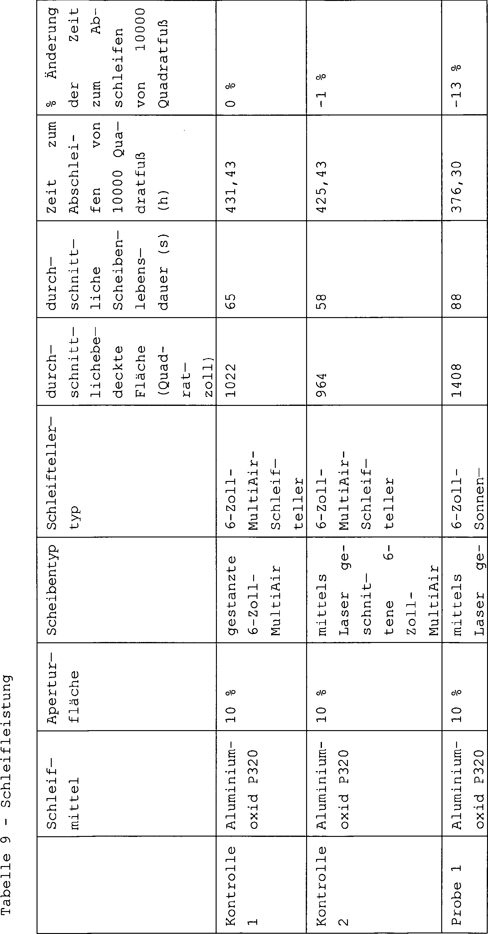

Beispiel 1 veranschaulicht, dass der Sonnenblumen-Schleifteller mit der MultiAir-Scheibe des Standes der Technik verwendbar war und dass die Paarung des Sonnenblumen-Schleiftellers im Vergleich zur Kontrolle 1 und zur Kontrolle 2 zu einer größeren abgeschliffenen Gesamtoberfläche und zu einer längeren Schleifscheibenlebensdauer beitrug. Die zum Abschleifen von 10000 Quadratfuß Plattenelement erforderliche Zeitdauer war um 13% verringert. Example 1 illustrates that the sunflower sanding pad was usable with the prior art MultiAir wheel and that the pairing of the sunflower sanding pad compared to
Beispiel 2 veranschaulicht, dass die Sonnenblumen-Schleifscheibe mit dem MultiAir-Schleifteller des Standes der Technik verwendbar war und dass die Paarung der Sonnenblumen-Schleifscheibe im Vergleich zur Kontrolle 1 und zur Kontrolle 2 zu einem größeren abgeschliffenen Gesamtflächeninhalt und zu einer längeren Schleifscheibenlebensdauer beitrug. Die zum Abschleifen von 10000 Quadratfuß Plattenelement erforderliche Zeitdauer war um 3% verringert.Example 2 illustrates that the sunflower sanding disc was usable with the prior art MultiAir sanding pad, and that the pairing of the sunflower sanding wheel compared to
Die Probe 3 veranschaulicht, dass die Paarung der Sonnenblumen-Schleifscheibe und des Sonnenblumen-Schleiftellers im Vergleich zu der Paarung der MultiAir-Scheibe und des MultiAir-Schleiftellers zu einem größeren abgeschliffenen Gesamtflächeninhalt und zu einer längeren Schleifscheibenlebensdauer beitrug. Ferner bot die Paarung der Sonnenblumen-Schleifscheibe und des Sonnenblumen-Schleiftellers den größten abgeschliffenen Gesamtflächeninhalt aller Testkombinationen. Die zum Abschleifen von 10000 Quadratfuß Plattenelement erforderliche Zeitdauer war um 24% verringert. Es wird angemerkt, dass die Verringerung von 24% synergistisch zu sein scheint, da die Verringerung größer als die Summe der Verringerung für Probe 1 (Sonnenblumen-Schleifteller –13% Verringerung) plus der Verringerung für Probe 2 (Sonnenblumen-Schleifscheibe –3% Verringerung) ist. Außerdem wird darauf hingewiesen, dass die Sonnenblumen-Schleifscheibe, selbst während sie eine kleinere Aperturfläche für die Abriebextraktion aufweist, eine höhere Schleifleistung erzielt.
Beispiel 9 – ZerspanungseffizienztestsExample 9 - Cutting Efficiency Tests
Um die Zerspanungseffizienz verschiedener Kombinationen von Schleifscheiben und Schleiftellern zu schätzen, wurde an Fahrzeugseitenplattenelementen ein Schleifleistungstest durchgeführt. Die Fahrzeugseitenplattenelemente waren aus Glasfaser und wie oben in Beispiel 8 mit einer Deckschicht galvanisiert. Die Fahrzeugseitenplattenelemente wurden unter Verwendung eines Handexzenterpolierers, der mit einer 6-Zoll-Schleifscheibe, mit einem Schleifteller und mit einem Unterdruckanbauteil wie in Beispiel 8 ausgestattet war, abgeschliffen. Es wurden drei erfindungsgemäße Proben und eine Kontrollprobe getestet. Abgesehen davon, dass die Schleifmittelkörnung Aluminiumoxid der Größe P80 war, waren die MultiAir- und die Sonnenblumen-Schleifscheiben dieselben wie oben für Beispiel 8. Die Kombinationen aus Schleifscheiben und Schleiftellern für die Kontrollprobe und für die erfindungsgemäßen Proben sind in Tabelle 10 gegeben und im Folgenden ausführlicher beschrieben.To estimate the cutting efficiency of various combinations of grinding wheels and grinding discs, a grinding performance test was performed on vehicle side plate members. The vehicle side panel members were made of fiberglass and plated with a topcoat as in Example 8 above. The vehicle side panel members were ground using a hand eccentric polisher equipped with a 6 inch abrasive disc, a sanding pad, and a vacuum attachment as in Example 8. Three samples according to the invention and one control sample were tested. Apart from the fact that the abrasive grain size was P80 alumina, the MultiAir and Sunflower abrasive wheels were the same as above for Example 8. The combinations of grinding wheels and sanding plates for the control and samples of the invention are given in Table 10 and below described in more detail.
Die Fahrzeugseitenplattenelemente wurden für alle Tests ebenso wie oben in Beispiel 8 unter Verwendung einer Bewegung von einer Seite zur Anderen, die aufeinanderfolgende Reihen über die Oberfläche des Plattenelements bedeckte, abgeschliffen. Es wurde eine einzelne Schleifscheibe verwendet, um ein gesteuertes Abschleifen über das Plattenelement bereitzustellen, bis das Ende der Lebensdauer der Scheibe erreicht war. Es wurden die Zeit bis zum Erreichen des Endes der Lebensdauer der Schleifscheibe und die abgeschliffene Gesamtfläche aufgezeichnet. Es wurde die Zerspanungseffizienz (abgeschliffene Gesamtfläche/Lebensdauer) berechnet.

Die Probe 1 und die Probe 2 veranschaulichten im Vergleich zur Kontrolle 1 eine Verbesserung der Zerspanungseffizienz und eine Verbesserung der abgeschliffenen Gesamtfläche. Die Probe 1 hatte im Vergleich zu Kontrolle 1 eine Verbesserung der Zerspanungseffizienz von 12% und die Probe 2 hatte im Vergleich zur Kontrolle 1 eine Verbesserung der Zerspanungseffizienz von 9%. The
Beispiel 10 – ZerspanungseffizienztestsExample 10 - Cutting Efficiency Tests
Um die Zerspanungseffizienz verschiedener Kombinationen von Schleifscheiben und Schleiftellern zu schätzen, wurde an Fahrzeugseitenplattenelementen ein Schleifleistungstest durchgeführt. Die Fahrzeugseitenplattenelemente waren aus Glasfaser und wie oben in Beispiel 9 mit einer Deckschicht galvanisiert. Die Fahrzeugseitenplattenelemente wurden unter Verwendung eines Handexzenterpolierers, der mit einer 6-Zoll-Schleifscheibe, mit einem Schleifteller und mit einem Unterdruckanbauteil wie in Beispiel 9 ausgestattet war, abgeschliffen. Es wurden drei erfindungsgemäße Proben und eine Kontrollprobe getestet. Abgesehen davon, dass die Schleifmittelkörnung ein Gemisch aus Keramikaluminiumoxid und Sol-Gel-Aluminiumoxid der Größe P80 war, waren die MultiAir- und die Sonnenblumen-Schleifscheiben dieselben wie oben für Beispiel 9. Die Kombinationen aus Schleifscheiben und Schleiftellern für die Kontrollprobe und für die erfindungsgemäßen Proben sind in Tabelle 6_ gegeben und im Folgenden ausführlicher beschrieben.To estimate the cutting efficiency of various combinations of grinding wheels and grinding discs, a grinding performance test was performed on vehicle side plate members. The vehicle side panel members were fiberglass and plated with a topcoat as in Example 9 above. The vehicle side panel members were ground using a hand eccentric polisher equipped with a 6 inch abrasive disc, a sanding pad, and a vacuum fixture as in Example 9. Three samples according to the invention and one control sample were tested. Apart from the fact that the abrasive grain size was a mixture of ceramic aluminum oxide and sol-gel alumina size P80, the MultiAir and sunflower abrasive wheels were the same as above for Example 9. The combinations of grinding wheels and sanding pads for the control sample and for the invention Samples are given in Table 6 and described in more detail below.
Die Fahrzeugseitenplattenelemente wurden für alle Tests ebenso wie oben in Beispiel 9 unter Verwendung einer Bewegung von einer Seite zur Anderen, die aufeinanderfolgende Reihen über die Oberfläche des Plattenelements bedeckte, abgeschliffen. Es wurde eine einzelne Schleifscheibe verwendet, um ein gesteuertes Abschleifen über das Plattenelement bereitzustellen, bis das Ende der Lebensdauer der Scheibe erreicht war. Es wurden die Zeit bis zum Erreichen des Endes der Lebensdauer der Schleifscheibe und die abgeschliffene Gesamtfläche aufgezeichnet. Es wurde die Zerspanungseffizienz (abgeschliffene Gesamtfläche/Lebensdauer) berechnet.

Die Probe 1 und die Probe 2 veranschaulichten im Vergleich zur Kontrolle 1 eine Verbesserung der Zerspanungsleistung und eine Verbesserung der abgeschliffenen Gesamtfläche. Die Probe 1 hatte im Vergleich zur Kontrolle 1 eine Verbesserung von 16% der Zerspanungseffizienz und die Probe 2 hatte gegenüber der Kontrolle 1 eine Verbesserung von 55% der Zerspanungseffizienz. The
Es wird angemerkt, dass nicht alle oben in der allgemeinen Beschreibung oder in den Beispielen beschriebenen Aktivitäten erforderlich sind und dass ein Teil einer spezifischen Aktivität nicht erforderlich sein kann und dass außer den Beschriebenen eine oder mehrere weitere Aktivitäten ausgeführt werden können. Nochmals weiter ist die Reihenfolge, in der die Aktivitäten aufgeführt sind, nicht notwendig die Reihenfolge, in der sie ausgeführt werden.It is noted that not all of the activities described above in the general description or examples are required and that a portion of a specific activity may not be required and that one or more other activities may be performed other than those described. Again, the order in which the activities are listed is not necessarily the order in which they are performed.
In der vorstehenden Beschreibung sind die Konzepte mit Bezug auf spezifische Ausführungsformen beschrieben worden. Allerdings wird der Durchschnittsfachmann auf dem Gebiet würdigen, dass verschiedene Abwandlungen und Änderungen vorgenommen werden können, ohne von dem wie in den folgenden Ansprüchen dargelegten Schutzumfang der Erfindung abzuweichen. Dementsprechend sind die Beschreibung und die Figuren in einem veranschaulichenden anstatt in einem einschränkenden Sinn anzusehen, wobei alle solche Abwandlungen im Schutzumfang der Erfindung enthalten sein sollen.In the foregoing description, the concepts have been described with reference to specific embodiments. However, one of ordinary skill in the art will appreciate that various modifications and changes can be made without departing from the scope of the invention as set forth in the following claims. Accordingly, the description and figures are to be considered in an illustrative rather than a limiting sense, all such modifications being intended to be included within the scope of the invention.
Wie sie hier verwendet sind, sollen die Begriffe ”umfasst”, ”umfassend”, ”enthält”, ”enthaltend”, ”weist auf”, ”aufweisend” oder irgendwelche anderen Abwandlungen davon einen nicht ausschließenden Einschluss umfassen. Zum Beispiel sind ein Prozess, ein Verfahren, ein Artikel oder eine Vorrichtung, der, das bzw. die eine Liste von Merkmalen umfasst, nicht notwendig nur auf diese Merkmale beschränkt, sondern kann er, es bzw. sie weitere Merkmale enthalten, die in diesem Prozess, in diesem Verfahren, in diesem Artikel oder in dieser Vorrichtung nicht explizit aufgeführt oder inhärent sind. Ferner bezieht sich ”oder”, sofern nicht explizit das Gegenteil angegeben ist, auf ein einschließendes Oder und nicht auf ein ausschließendes Oder. Zum Beispiel ist eine Bedingung A oder B durch eines der Folgenden erfüllt: A ist wahr (oder vorhanden) und B ist falsch (oder nicht vorhanden), A ist falsch (oder nicht vorhanden) und B ist wahr (oder vorhanden) und sowohl A als auch B ist wahr (oder vorhanden).As used herein, the terms "comprising," "comprising," "containing," "containing," "having," "having," or any other variations thereof, is intended to include a non-exclusive inclusion. For example, a process, method, article, or device that includes a list of features is not necessarily limited to only those features, but rather may include other features contained therein Process, in this process, in this article or in this device are not explicitly listed or inherent. Further, unless otherwise indicated, "or" refers to an inclusive, and not to an exclusive, or disclaimer. For example, an A or B condition is satisfied by one of the following: A is true (or exists) and B is false (or absent), A is false (or absent), and B is true (or exists) and both are A and B is true (or exists).
Außerdem ist die Verwendung von ”ein” oder ”eine” zur Beschreibung von hier beschriebenen Elementen und Komponenten genutzt. Dies erfolgt nur zweckmäßigkeitshalber und um eine allgemeine Vorstellung vom Schutzumfang der Erfindung zu geben. Diese Beschreibung ist so zu lesen, dass sie eines oder wenigstens eines enthält, wobei der Singular ebenfalls den Plural einschließt, es sei denn, dass dies offensichtlich anders gemeint ist.In addition, the use of "on" or "an" is used to describe elements and components described herein. This is only for convenience and to give a general idea of the scope of the invention. This description is read to include one or at least one, the singular also including the plural, unless obviously meant otherwise.
Vorzüge, weitere Vorteile und Lösungen für Probleme sind oben hinsichtlich spezifischer Ausführungsformen beschrieben worden. Allerdings sollen die Vorzüge, Vorteile, Lösungen für Probleme und irgendwelche Merkmal(e), die veranlassen können, dass irgendein Vorzug, irgendein Vorteil oder irgendeine Lösung erscheint oder verstärkt wird, nicht als kritisches, erforderliches oder wesentliches Merkmal irgendwelcher Ansprüche anzusehen.Advantages, other advantages, and solutions to problems have been described above with respect to specific embodiments. However, the merits, advantages, solutions to problems, and any feature (s) that may cause any merit, advantage, or solution to appear or be augmented, should not be construed as a critical, required, or essential feature of any claims.
Nach Lesen der Beschreibung wird der Fachmann würdigen, dass bestimmte Merkmale, die hier zur Klarheit im Kontext getrennter Ausführungsformen beschrieben sind, ebenfalls zusammen in einer einzelnen Ausführungsform bereitgestellt sein können. Umgekehrt können verschiedene Merkmale, die der Kürze halber im Kontext einer einzelnen Ausführungsform beschrieben sind, ebenfalls getrennt in irgendeiner Teilkombination bereitgestellt sein. Ferner enthalten Bezugnahmen auf Werte, die in Bereichen angegeben sind, jeden Wert innerhalb dieses Bereichs.After reading the description, those skilled in the art will appreciate that certain features, which are described herein for clarity in the context of separate embodiments, may also be provided together in a single embodiment. Conversely, various features, which for the sake of brevity are described in the context of a single embodiment, may also be provided separately in any subcombination. Further, references to values indicated in ranges include any value within that range.
ZITATE ENTHALTEN IN DER BESCHREIBUNG QUOTES INCLUDE IN THE DESCRIPTION
Diese Liste der vom Anmelder aufgeführten Dokumente wurde automatisiert erzeugt und ist ausschließlich zur besseren Information des Lesers aufgenommen. Die Liste ist nicht Bestandteil der deutschen Patent- bzw. Gebrauchsmusteranmeldung. Das DPMA übernimmt keinerlei Haftung für etwaige Fehler oder Auslassungen.This list of the documents listed by the applicant has been generated automatically and is included solely for the better information of the reader. The list is not part of the German patent or utility model application. The DPMA assumes no liability for any errors or omissions.
Zitierte PatentliteraturCited patent literature
- US 5700302 [0103] US 5700302 [0103]
- US 5108463 [0104] US 5108463 [0104]
- US 5137542 [0104] US 5137542 [0104]
- US 5328716 [0104] US 5,327,816 [0104]
- US 5560753 [0104] US 5560753 [0104]
- US 5417726 [0105] US 5417726 [0105]
- US 5573619 [0105] US 5573619 [0105]
- US 5505747 [0105] US 5505747 [0105]
- US 5565011 [0105] US 5565011 [0105]
Zitierte Nicht-PatentliteraturCited non-patent literature
- Jean's Phyllotaxis A Systemic Study in Plant Morphogenesis, S. 17 [0076] Jean's Phyllotaxis A Systemic Study in Plant Morphogenesis, p. 17 [0076]
Claims (58)


Applications Claiming Priority (3)
| Application Number | Priority Date | Filing Date | Title |
|---|---|---|---|
| US201161582308P | 2011-12-31 | 2011-12-31 | |
| US61/582,308 | 2011-12-31 | ||
| PCT/US2012/072304 WO2013102206A1 (en) | 2011-12-31 | 2012-12-31 | Abrasive article having a non-uniform distribution of openings |
Publications (1)
| Publication Number | Publication Date |
|---|---|
| DE212012000041U1 true DE212012000041U1 (en) | 2013-10-14 |
Family
ID=48698700
Family Applications (1)
| Application Number | Title | Priority Date | Filing Date |
|---|---|---|---|
| DE212012000041U Expired - Lifetime DE212012000041U1 (en) | 2011-12-31 | 2012-12-31 | Abrasive article having a non-uniform distribution of apertures |
Country Status (14)
| Country | Link |
|---|---|
| US (3) | US9656366B2 (en) |
| EP (3) | EP3613540A1 (en) |
| JP (2) | JP5779727B2 (en) |
| KR (1) | KR101671708B1 (en) |
| CN (2) | CN106002638B (en) |
| AU (1) | AU2012362116B2 (en) |
| BR (1) | BR112014016015B1 (en) |
| CA (2) | CA2973965A1 (en) |
| CH (4) | CH708721B1 (en) |
| DE (1) | DE212012000041U1 (en) |
| MX (1) | MX356390B (en) |
| RU (1) | RU2603747C2 (en) |
| TW (1) | TWI523732B (en) |
| WO (1) | WO2013102206A1 (en) |
Cited By (1)
| Publication number | Priority date | Publication date | Assignee | Title |
|---|---|---|---|---|
| DE102017216175A1 (en) * | 2017-09-13 | 2019-03-14 | Robert Bosch Gmbh | abrasive article |
Families Citing this family (50)
| Publication number | Priority date | Publication date | Assignee | Title |
|---|---|---|---|---|
| WO2011031483A2 (en) | 2009-08-25 | 2011-03-17 | Cambrios Technologies Corporation | Methods for controlling metal nanostructures morphology |
| EP3517245B1 (en) | 2011-12-30 | 2023-12-13 | Saint-Gobain Ceramics & Plastics Inc. | Shaped abrasive particle and method of forming same |
| CH708721B1 (en) | 2011-12-31 | 2015-04-30 | Saint Gobain Abrasives Inc | Grinding device. |
| CA2987793C (en) | 2012-01-10 | 2019-11-05 | Saint-Gobain Ceramics & Plastics, Inc. | Abrasive particles having complex shapes and methods of forming same |
| DE202012013026U1 (en) * | 2012-01-31 | 2014-07-15 | Robert Bosch Gmbh | unit |
| CN104822494B (en) | 2012-10-15 | 2017-11-28 | 圣戈班磨料磨具有限公司 | The method of abrasive particle and this particle of formation with given shape |
| JP6356404B2 (en) * | 2012-10-31 | 2018-07-11 | 豊田バンモップス株式会社 | Electrodeposition wheel and method for producing electrodeposition wheel |
| CN107685296B (en) | 2013-03-29 | 2020-03-06 | 圣戈班磨料磨具有限公司 | Abrasive particles having a particular shape, methods of forming such particles, and uses thereof |
| TWI589404B (en) * | 2013-06-28 | 2017-07-01 | 聖高拜磨料有限公司 | Coated abrasive article based on a sunflower pattern |
| GB2515764A (en) * | 2013-07-02 | 2015-01-07 | 3M Innovative Properties Co | Abrasive article and adapter therefore |
| JP6290428B2 (en) | 2013-12-31 | 2018-03-07 | サンーゴバン アブレイシブズ,インコーポレイティド | Abrasive articles containing shaped abrasive particles |
| US9771507B2 (en) | 2014-01-31 | 2017-09-26 | Saint-Gobain Ceramics & Plastics, Inc. | Shaped abrasive particle including dopant material and method of forming same |
| CN103878670B (en) * | 2014-03-06 | 2016-05-18 | 浙江工业大学 | A kind of plane polishing device |
| CN103878679B (en) * | 2014-03-06 | 2016-05-18 | 浙江工业大学 | A kind of double freedom plane polishing device |
| AU2015247826A1 (en) | 2014-04-14 | 2016-11-10 | Saint-Gobain Ceramics & Plastics, Inc. | Abrasive article including shaped abrasive particles |
| CN106457524A (en) * | 2014-05-01 | 2017-02-22 | 3M创新有限公司 | Coated abrasive article |
| SG11201608996TA (en) * | 2014-05-02 | 2016-11-29 | 3M Innovative Properties Co | Interrupted structured abrasive article and methods of polishing a workpiece |
| JP6450897B2 (en) * | 2014-08-08 | 2019-01-09 | 明男 日詰 | 3D structure |
| US9914864B2 (en) | 2014-12-23 | 2018-03-13 | Saint-Gobain Ceramics & Plastics, Inc. | Shaped abrasive particles and method of forming same |
| WO2016109734A1 (en) | 2014-12-30 | 2016-07-07 | Saint-Gobain Abrasives, Inc. | Abrasive tools and methods for forming same |
| US10363703B2 (en) * | 2015-01-16 | 2019-07-30 | Within Technologies Ltd. | Radial lattice structures for additive manufacturing |
| TWI690391B (en) * | 2015-03-04 | 2020-04-11 | 美商聖高拜磨料有限公司 | Abrasive article and method of use |
| TWI634200B (en) | 2015-03-31 | 2018-09-01 | 聖高拜磨料有限公司 | Fixed abrasive articles and methods of forming same |
| WO2016161157A1 (en) * | 2015-03-31 | 2016-10-06 | Saint-Gobain Abrasives, Inc. | Fixed abrasive articles and methods of forming same |
| US10687613B2 (en) | 2015-05-07 | 2020-06-23 | Craig R. Smith | Rotary cleaning tool for commode surfaces |
| JP2018516767A (en) | 2015-06-11 | 2018-06-28 | サン−ゴバン セラミックス アンド プラスティクス,インコーポレイティド | Abrasive articles containing shaped abrasive particles |
| CN105126684B (en) * | 2015-08-05 | 2017-07-18 | 沈阳理工大学 | A kind of micro-mixer of end face phyllotaxy arrangement |
| CN105161472B (en) * | 2015-08-05 | 2018-08-24 | 沈阳理工大学 | A kind of needle pillar minitype radiator of end face phyllotaxy arrangement |
| US10464367B1 (en) * | 2015-09-18 | 2019-11-05 | Gem2, Llc | Gem applicator assembly |
| US10358722B2 (en) * | 2015-12-14 | 2019-07-23 | Lam Research Corporation | Showerhead assembly |
| AU2016381202B2 (en) | 2015-12-30 | 2019-03-14 | Saint-Gobain Abrasifs | Abrasive tools and methods for forming same |
| JP6444935B2 (en) * | 2016-04-28 | 2018-12-26 | ファナック株式会社 | Numerical control device for determining chip accumulation |
| EP4071224A3 (en) | 2016-05-10 | 2023-01-04 | Saint-Gobain Ceramics and Plastics, Inc. | Methods of forming abrasive articles |
| PL3255370T3 (en) * | 2016-06-06 | 2020-05-18 | Aerco International, Inc. | Fibonacci optimized radial heat exchanger |
| SG10202101268QA (en) * | 2016-08-10 | 2021-03-30 | Klingspor Ag | Roughing disc having a backing layer |
| USD816132S1 (en) * | 2016-09-08 | 2018-04-24 | Mirka Ltd | Abrasive disc |
| USD816131S1 (en) * | 2016-09-08 | 2018-04-24 | Mirka Ltd | Abrasive disc |
| EP4349896A2 (en) | 2016-09-29 | 2024-04-10 | Saint-Gobain Abrasives, Inc. | Fixed abrasive articles and methods of forming same |
| US10563105B2 (en) | 2017-01-31 | 2020-02-18 | Saint-Gobain Ceramics & Plastics, Inc. | Abrasive article including shaped abrasive particles |
| DE102017216033A1 (en) * | 2017-09-12 | 2019-03-14 | Carl Zeiss Smt Gmbh | Method for processing a workpiece in the manufacture of an optical element |
| WO2019102330A1 (en) * | 2017-11-21 | 2019-05-31 | 3M Innovative Properties Company | Coated abrasive disc and methods of making and using the same |
| US11597059B2 (en) | 2017-11-21 | 2023-03-07 | 3M Innovative Properties Company | Coated abrasive disc and methods of making and using the same |
| CN111372727B (en) | 2017-11-21 | 2022-02-15 | 3M创新有限公司 | Coated abrasive discs and methods of making and using the same |
| WO2020018018A1 (en) * | 2018-07-18 | 2020-01-23 | Nanyang Technological University | Polishing tool |
| DE102018131590A1 (en) * | 2018-12-10 | 2020-06-10 | Dongguan Golden Sun Abrasives Co., Ltd. | Disc sanding paper and grinder |
| US11331767B2 (en) * | 2019-02-01 | 2022-05-17 | Micron Technology, Inc. | Pads for chemical mechanical planarization tools, chemical mechanical planarization tools, and related methods |
| IT201900001286U1 (en) * | 2019-04-15 | 2020-10-15 | Alesia Inc S R L | CIRCULAR SHAPE ABRASIVE DEVICE |
| CN109938362B (en) * | 2019-04-30 | 2021-06-11 | 广西壮族自治区农业科学院 | Automatic change peanut shell processingequipment |
| KR20220116556A (en) | 2019-12-27 | 2022-08-23 | 세인트-고바인 세라믹스 앤드 플라스틱스, 인크. | Abrasive articles and methods of forming same |
| US11359652B2 (en) * | 2020-03-10 | 2022-06-14 | Paul Van Buskirk | Orifice plates |
Citations (9)
| Publication number | Priority date | Publication date | Assignee | Title |
|---|---|---|---|---|
| US5108463A (en) | 1989-08-21 | 1992-04-28 | Minnesota Mining And Manufacturing Company | Conductive coated abrasives |
| US5137542A (en) | 1990-08-08 | 1992-08-11 | Minnesota Mining And Manufacturing Company | Abrasive printed with an electrically conductive ink |
| US5328716A (en) | 1992-08-11 | 1994-07-12 | Minnesota Mining And Manufacturing Company | Method of making a coated abrasive article containing a conductive backing |
| US5417726A (en) | 1991-12-20 | 1995-05-23 | Minnesota Mining And Manufacturing Company | Coated abrasive backing |
| US5505747A (en) | 1994-01-13 | 1996-04-09 | Minnesota Mining And Manufacturing Company | Method of making an abrasive article |
| US5560753A (en) | 1992-02-12 | 1996-10-01 | Minnesota Mining And Manufacturing Company | Coated abrasive article containing an electrically conductive backing |
| US5565011A (en) | 1993-10-19 | 1996-10-15 | Minnesota Mining And Manufacturing Company | Abrasive article comprising a make coat transferred by lamination and methods of making same |
| US5573619A (en) | 1991-12-20 | 1996-11-12 | Minnesota Mining And Manufacturing Company | Method of making a coated abrasive belt with an endless, seamless backing |
| US5700302A (en) | 1996-03-15 | 1997-12-23 | Minnesota Mining And Manufacturing Company | Radiation curable abrasive article with tie coat and method |
Family Cites Families (69)
| Publication number | Priority date | Publication date | Assignee | Title |
|---|---|---|---|---|
| FR1390205A (en) | 1963-06-04 | 1965-02-26 | Zane & C Snc | Flexible abrasive disc, process for its manufacture and means for carrying out this process |
| US3426486A (en) | 1964-11-16 | 1969-02-11 | Landis Tool Co | Abrasive disc |
| FR2365411A1 (en) | 1976-09-27 | 1978-04-21 | Robert Jean | SANDPAPER DISC SANDER MOUNTED ON A ROTATING CIRCULAR PLATE |
| JPH0123731Y2 (en) | 1985-05-10 | 1989-07-20 | ||
| US5309682A (en) * | 1990-03-28 | 1994-05-10 | Robert Bosch Gmbh | Hand held power tool with working disc |
| US5152917B1 (en) | 1991-02-06 | 1998-01-13 | Minnesota Mining & Mfg | Structured abrasive article |
| JP3076072B2 (en) * | 1991-02-19 | 2000-08-14 | 日本電気株式会社 | Loudspeaker apparatus and noise suppression circuit used in the apparatus |
| IT1273769B (en) * | 1994-02-15 | 1997-07-10 | Catalfer S N C Di Catalfamo Gi | SYSTEM FOR THE SIDE FIXING OF THE ROTARY SANDING MACHINES TO THE INTERCHANGEABLE ABRASIVE DISCS |
| US5650039A (en) | 1994-03-02 | 1997-07-22 | Applied Materials, Inc. | Chemical mechanical polishing apparatus with improved slurry distribution |
| US5674122A (en) | 1994-10-27 | 1997-10-07 | Minnesota Mining And Manufacturing Company | Abrasive articles and methods for their manufacture |
| US5692949A (en) * | 1995-11-17 | 1997-12-02 | Minnesota Mining And Manufacturing Company | Back-up pad for use with abrasive articles |
| EP0874717B1 (en) * | 1995-12-08 | 2005-08-31 | Norton Company | Backing plates for abrasive disks |
| DE29520566U1 (en) | 1995-12-29 | 1996-02-22 | Joest Peter | Abrasives that can be adapted directly or indirectly with a machine or a manually operated abrasive holder as well as a suitable adapter |
| US5807161A (en) * | 1996-03-15 | 1998-09-15 | Minnesota Mining And Manufacturing Company | Reversible back-up pad |
| US5842910A (en) | 1997-03-10 | 1998-12-01 | International Business Machines Corporation | Off-center grooved polish pad for CMP |
| JPH11239979A (en) | 1998-02-23 | 1999-09-07 | Noritake Diamond Ind Co Ltd | Rotary grinding wheel |
| US5989112A (en) | 1998-05-11 | 1999-11-23 | Norton Company | Universal abrasive disc |
| US6059644A (en) * | 1998-11-18 | 2000-05-09 | 3M Innovative Properties Company | Back-up pad for abrasive articles and method of making |
| US6281681B1 (en) | 1999-01-28 | 2001-08-28 | General Electric Company | Magnetic resonance imaging with interleaved Fibonacci spiral scanning |
| DE19945060B4 (en) | 1999-09-20 | 2010-12-02 | Robert Bosch Gmbh | Sander machine |
| US6699143B2 (en) | 1999-10-14 | 2004-03-02 | Acushnet Company | Phyllotaxis-based dimple patterns |
| US6338684B1 (en) | 1999-10-14 | 2002-01-15 | Acushnet Company | Phyllotaxis-based dimple patterns |
| US6656019B1 (en) | 2000-06-29 | 2003-12-02 | International Business Machines Corporation | Grooved polishing pads and methods of use |
| US6368078B1 (en) | 2000-11-27 | 2002-04-09 | John F. Palumbo | Bladeless turbocharger |
| US7108594B2 (en) | 2001-03-16 | 2006-09-19 | Saint-Gobain Abrasives Technology Company | Perforated sanding disc |
| JP2003071731A (en) * | 2001-09-03 | 2003-03-12 | Three M Innovative Properties Co | Dimple structure abrasive material |
| US20050194681A1 (en) * | 2002-05-07 | 2005-09-08 | Yongqi Hu | Conductive pad with high abrasion |
| JP2004071985A (en) | 2002-08-08 | 2004-03-04 | Jsr Corp | Working method for grinding pad for semiconductor wafer and grinding pad for semiconductor wafer |
| TWI228768B (en) | 2002-08-08 | 2005-03-01 | Jsr Corp | Processing method of polishing pad for semiconductor wafer and polishing pad for semiconductor wafer |
| TWI238753B (en) | 2002-12-19 | 2005-09-01 | Miyanaga Kk | Diamond disk for grinding |
| US20050076577A1 (en) | 2003-10-10 | 2005-04-14 | Hall Richard W.J. | Abrasive tools made with a self-avoiding abrasive grain array |
| CN2701589Y (en) * | 2004-04-06 | 2005-05-25 | 陈信宇 | Abrasive disc with improved structure |
| US8002612B2 (en) * | 2004-04-08 | 2011-08-23 | 3M Innovative Properties Company | Attachment system for a sanding tool |
| US20060019579A1 (en) | 2004-07-26 | 2006-01-26 | Braunschweig Ehrich J | Non-loading abrasive article |
| FI121653B (en) * | 2005-06-13 | 2011-02-28 | Kwh Mirka Ab Oy | Flexible abrasive product and method for its production |
| US7252694B2 (en) | 2005-08-05 | 2007-08-07 | 3M Innovative Properties Company | Abrasive article and methods of making same |
| USD538313S1 (en) | 2005-09-16 | 2007-03-13 | 3M Innovative Properties Company | Abrasive article with holes |
| US7244170B2 (en) | 2005-09-16 | 2007-07-17 | 3M Innovative Properties Co. | Abrasive article and methods of making same |
| USD536714S1 (en) | 2005-09-16 | 2007-02-13 | 3M Innovative Properties Company | Abrasive article with holes |
| USD538312S1 (en) | 2005-09-16 | 2007-03-13 | 3M Innovative Properties Company | Abrasive article with holes |
| US7390244B2 (en) | 2005-09-16 | 2008-06-24 | 3M Innovative Properties Company | Abrasive article mounting assembly and methods of making same |
| US7393269B2 (en) | 2005-09-16 | 2008-07-01 | 3M Innovative Properties Company | Abrasive filter assembly and methods of making same |
| TW200744786A (en) * | 2005-12-28 | 2007-12-16 | Jsr Corp | Chemical mechanical polishing pad and chemical mechanical polishing method |
| USD533200S1 (en) | 2006-02-01 | 2006-12-05 | 3M Innovative Properties Company | Abrasive article with holes |
| USD541317S1 (en) * | 2006-02-01 | 2007-04-24 | 3M Innovative Properties Company | Abrasive article with holes |
| USD532800S1 (en) | 2006-02-01 | 2006-11-28 | 3M Innovative Properties Company | Abrasive article with holes |
| USD543562S1 (en) * | 2006-02-01 | 2007-05-29 | 3M Innovative Properties Company | Abrasive article with holes |
| JP2007283426A (en) * | 2006-04-14 | 2007-11-01 | Three M Innovative Properties Co | Dust sucking polisher |
| JP2008087082A (en) * | 2006-09-29 | 2008-04-17 | Three M Innovative Properties Co | Grinding tool for sucking dust |
| US7452265B2 (en) * | 2006-12-21 | 2008-11-18 | 3M Innovative Properties Company | Abrasive article and methods of making same |
| US7959694B2 (en) | 2007-03-05 | 2011-06-14 | 3M Innovative Properties Company | Laser cut abrasive article, and methods |
| US8080072B2 (en) * | 2007-03-05 | 2011-12-20 | 3M Innovative Properties Company | Abrasive article with supersize coating, and methods |
| US7628829B2 (en) * | 2007-03-20 | 2009-12-08 | 3M Innovative Properties Company | Abrasive article and method of making and using the same |
| DE202007004949U1 (en) | 2007-04-02 | 2007-06-06 | Ufi Schleiftechnik Gmbh & Co. Kg | Grinder with a rotating plate, to hold a grinding disk, has concentric circles of suction openings to extract dust |
| JP2008290197A (en) * | 2007-05-25 | 2008-12-04 | Nihon Micro Coating Co Ltd | Polishing pad and method |
| US20080318506A1 (en) | 2007-06-19 | 2008-12-25 | John Edward Brown | Abrasive article and method of making |
| US7441927B1 (en) | 2007-07-02 | 2008-10-28 | Osram Sylvania Inc. | Lamp with a lens lenticule pattern based on the golden ratio |
| USD586370S1 (en) * | 2007-08-09 | 2009-02-10 | 3M Innovative Properties Company | Random hole abrasive disc |
| USD582684S1 (en) | 2007-08-17 | 2008-12-16 | 3M Innovative Properties Company | Abrasive article with holes |
| USD572019S1 (en) | 2007-08-17 | 2008-07-01 | 3M Innovative Properties Company | Abrasive article with holes |
| CA2710999A1 (en) | 2007-12-31 | 2009-07-16 | Mervyn Chung-Fat | Interface pad for use between an abrasive article and a support tool |
| USD645065S1 (en) | 2008-05-22 | 2011-09-13 | 3M Innovative Properties Company | Abrasive article with holes |
| ITMI20080222U1 (en) | 2008-07-15 | 2010-01-16 | Valentini Guido | "CUP FOR WORKING SURFACES WITH CURVED SUCTION CHANNELS" |
| US7927234B2 (en) | 2009-01-29 | 2011-04-19 | Acushnet Company | Golf ball dimple patterns with multiple phyllotactic elements |
| ITMI20091483A1 (en) | 2009-08-17 | 2011-02-18 | Cemom Moatti | SUPPORT OF ABRASIVE ELEMENTS IN THE FORM OF A SHEET FOR TOOLS OR TOOL MACHINES |
| DE102009050662B4 (en) | 2009-10-26 | 2012-09-27 | Siemens Aktiengesellschaft | Radial MR data acquisition in a three-dimensional K-space with an arrangement of the spokes according to a spiral phyllotaxis |
| CN101885164B (en) * | 2010-06-08 | 2011-12-14 | 沈阳理工大学 | Tin solidified diamond abrasive polishing pad with bionic structure and manufacturing method |
| CH708721B1 (en) | 2011-12-31 | 2015-04-30 | Saint Gobain Abrasives Inc | Grinding device. |
| DE202012013026U1 (en) | 2012-01-31 | 2014-07-15 | Robert Bosch Gmbh | unit |
-
2012
- 2012-12-31 CH CH00726/14A patent/CH708721B1/en unknown
- 2012-12-31 DE DE212012000041U patent/DE212012000041U1/en not_active Expired - Lifetime
- 2012-12-31 CA CA2973965A patent/CA2973965A1/en not_active Abandoned
- 2012-12-31 AU AU2012362116A patent/AU2012362116B2/en active Active
- 2012-12-31 MX MX2014007883A patent/MX356390B/en active IP Right Grant
- 2012-12-31 EP EP19183910.9A patent/EP3613540A1/en active Pending
- 2012-12-31 WO PCT/US2012/072304 patent/WO2013102206A1/en active Application Filing
- 2012-12-31 KR KR1020147020036A patent/KR101671708B1/en active IP Right Grant
- 2012-12-31 US US13/731,768 patent/US9656366B2/en active Active
- 2012-12-31 JP JP2014550540A patent/JP5779727B2/en active Active
- 2012-12-31 CN CN201610326222.1A patent/CN106002638B/en active Active
- 2012-12-31 RU RU2014130168/02A patent/RU2603747C2/en not_active IP Right Cessation
- 2012-12-31 CN CN201280069816.9A patent/CN104125876B/en active Active
- 2012-12-31 EP EP16168746.2A patent/EP3072639B1/en active Active
- 2012-12-31 EP EP12861139.9A patent/EP2797714B1/en active Active
- 2012-12-31 CH CH01762/14A patent/CH709387B8/en unknown
- 2012-12-31 CH CH01453/13A patent/CH706386B1/en unknown
- 2012-12-31 BR BR112014016015-5A patent/BR112014016015B1/en active IP Right Grant
- 2012-12-31 CH CH01761/14A patent/CH709583B1/en unknown
- 2012-12-31 CA CA2862388A patent/CA2862388C/en active Active
-
2013
- 2013-01-02 TW TW101151118A patent/TWI523732B/en not_active IP Right Cessation
-
2015
- 2015-05-26 JP JP2015106124A patent/JP6018260B2/en active Active
-
2017
- 2017-04-07 US US15/481,526 patent/US10076820B2/en active Active
-
2018
- 2018-08-17 US US16/104,649 patent/US11504822B2/en active Active
Patent Citations (10)
| Publication number | Priority date | Publication date | Assignee | Title |
|---|---|---|---|---|
| US5108463A (en) | 1989-08-21 | 1992-04-28 | Minnesota Mining And Manufacturing Company | Conductive coated abrasives |
| US5108463B1 (en) | 1989-08-21 | 1996-08-13 | Minnesota Mining & Mfg | Conductive coated abrasives |
| US5137542A (en) | 1990-08-08 | 1992-08-11 | Minnesota Mining And Manufacturing Company | Abrasive printed with an electrically conductive ink |
| US5417726A (en) | 1991-12-20 | 1995-05-23 | Minnesota Mining And Manufacturing Company | Coated abrasive backing |
| US5573619A (en) | 1991-12-20 | 1996-11-12 | Minnesota Mining And Manufacturing Company | Method of making a coated abrasive belt with an endless, seamless backing |
| US5560753A (en) | 1992-02-12 | 1996-10-01 | Minnesota Mining And Manufacturing Company | Coated abrasive article containing an electrically conductive backing |
| US5328716A (en) | 1992-08-11 | 1994-07-12 | Minnesota Mining And Manufacturing Company | Method of making a coated abrasive article containing a conductive backing |
| US5565011A (en) | 1993-10-19 | 1996-10-15 | Minnesota Mining And Manufacturing Company | Abrasive article comprising a make coat transferred by lamination and methods of making same |
| US5505747A (en) | 1994-01-13 | 1996-04-09 | Minnesota Mining And Manufacturing Company | Method of making an abrasive article |
| US5700302A (en) | 1996-03-15 | 1997-12-23 | Minnesota Mining And Manufacturing Company | Radiation curable abrasive article with tie coat and method |
Non-Patent Citations (1)
| Title |
|---|
| Jean's Phyllotaxis A Systemic Study in Plant Morphogenesis, S. 17 |
Cited By (2)
| Publication number | Priority date | Publication date | Assignee | Title |
|---|---|---|---|---|
| DE102017216175A1 (en) * | 2017-09-13 | 2019-03-14 | Robert Bosch Gmbh | abrasive article |
| US11697186B2 (en) | 2017-09-13 | 2023-07-11 | Robert Bosch Gmbh | Abrasive article |
Also Published As
Similar Documents
| Publication | Publication Date | Title |
|---|---|---|
| DE212012000041U1 (en) | Abrasive article having a non-uniform distribution of apertures | |
| JP6805292B2 (en) | Coated abrasive product based on sunflower pattern |
Legal Events
| Date | Code | Title | Description |
|---|---|---|---|
| R082 | Change of representative |
Representative=s name: ZIMMERMANN & PARTNER, DE Representative=s name: ZIMMERMANN & PARTNER PATENTANWAELTE MBB, DE |
|
| R207 | Utility model specification |
Effective date: 20131205 |
|
| R150 | Utility model maintained after payment of first maintenance fee after three years | ||
| R151 | Utility model maintained after payment of second maintenance fee after six years | ||
| R152 | Utility model maintained after payment of third maintenance fee after eight years | ||
| R071 | Expiry of right |