DE10312154A1 - Object orientation tracking procedure uses Kalman filtered inertial and magnetic field sensors with offset determination and subtraction for Quaternion algorithm - Google Patents
Object orientation tracking procedure uses Kalman filtered inertial and magnetic field sensors with offset determination and subtraction for Quaternion algorithm Download PDFInfo
- Publication number
- DE10312154A1 DE10312154A1 DE10312154A DE10312154A DE10312154A1 DE 10312154 A1 DE10312154 A1 DE 10312154A1 DE 10312154 A DE10312154 A DE 10312154A DE 10312154 A DE10312154 A DE 10312154A DE 10312154 A1 DE10312154 A1 DE 10312154A1
- Authority
- DE
- Germany
- Prior art keywords
- orientation
- sensors
- rotation rate
- signals
- rotation
- Prior art date
- Legal status (The legal status is an assumption and is not a legal conclusion. Google has not performed a legal analysis and makes no representation as to the accuracy of the status listed.)
- Granted
Links
Classifications
-
- A—HUMAN NECESSITIES
- A61—MEDICAL OR VETERINARY SCIENCE; HYGIENE
- A61B—DIAGNOSIS; SURGERY; IDENTIFICATION
- A61B5/00—Measuring for diagnostic purposes; Identification of persons
- A61B5/103—Detecting, measuring or recording devices for testing the shape, pattern, colour, size or movement of the body or parts thereof, for diagnostic purposes
- A61B5/11—Measuring movement of the entire body or parts thereof, e.g. head or hand tremor, mobility of a limb
- A61B5/1113—Local tracking of patients, e.g. in a hospital or private home
- A61B5/1114—Tracking parts of the body
-
- G—PHYSICS
- G01—MEASURING; TESTING
- G01C—MEASURING DISTANCES, LEVELS OR BEARINGS; SURVEYING; NAVIGATION; GYROSCOPIC INSTRUMENTS; PHOTOGRAMMETRY OR VIDEOGRAMMETRY
- G01C21/00—Navigation; Navigational instruments not provided for in groups G01C1/00 - G01C19/00
- G01C21/10—Navigation; Navigational instruments not provided for in groups G01C1/00 - G01C19/00 by using measurements of speed or acceleration
- G01C21/12—Navigation; Navigational instruments not provided for in groups G01C1/00 - G01C19/00 by using measurements of speed or acceleration executed aboard the object being navigated; Dead reckoning
- G01C21/16—Navigation; Navigational instruments not provided for in groups G01C1/00 - G01C19/00 by using measurements of speed or acceleration executed aboard the object being navigated; Dead reckoning by integrating acceleration or speed, i.e. inertial navigation
- G01C21/183—Compensation of inertial measurements, e.g. for temperature effects
-
- A—HUMAN NECESSITIES
- A61—MEDICAL OR VETERINARY SCIENCE; HYGIENE
- A61B—DIAGNOSIS; SURGERY; IDENTIFICATION
- A61B2562/00—Details of sensors; Constructional details of sensor housings or probes; Accessories for sensors
- A61B2562/02—Details of sensors specially adapted for in-vivo measurements
- A61B2562/0219—Inertial sensors, e.g. accelerometers, gyroscopes, tilt switches
Abstract
Description
Die Erfindung betrifft ein Verfahren und eine Vorrichtung zum Ausführen einer Objektverfolgung, wobei mittels einer drei Drehratensensoren umfassenden Vorrichtung Messdaten ermittelt und hieraus durch Integration drei Drehwinkel zur weiteren Bestimmung der Orientierung des Objekts im Raum errechnet werden, wobei die Ermittlung der Messdaten und die Errechnung der drei Drehwinkel quasikontinuierlich entsprechend einer Abtastrate durchgeführt wird und wobei die Orientierung des Objekts im Raum angezeigt oder in an sich beliebiger Weise weiterer Datenverarbeitung zugeführt oder zu Steuerungsprozessen verwendet werden kann.The invention relates to a method and a device for executing an object tracking, by means of a three rotation rate sensors comprehensive device measured data and derived from it by integration three angles of rotation to further determine the orientation of the object be calculated in the room, the determination of the measurement data and the calculation of the three angles of rotation quasi-continuously accordingly a sampling rate and and the orientation of the object in space is displayed or in any way further data processing supplied or can be used for control processes.
Ein Verfahren und eine Vorrichtung
der vorstehend genannten Art ist bekannt aus
Gemäß einem zweiten Ausführungsbeispiel wird ein dreiachsiger Beschleunigungssensor und ein zweiachsiger Drehratensensor, also zwei bezüglich zweier Richtungen ausgerichtete und sensitive Drehratensensoren, verwendet. Die Verwendung von Beschleunigungssensoren ist jedoch nur so lange einfach handhabbar, so lange keine translatorische Bewegung hinzukommt. Schließlich wird nach einer dritten Ausführungsform ein dreiachsiger Beschleunigungssensor und ein einziger Drehratensensor verwendet. Auch gemäß dieser Druckschrift wird während eines temporären Stillstands zur Verbesserung des Driftproblems der Integrator "resettet" oder zurückgesetzt. Dennoch ist für die Berechnung der drei Orientierungswinkel für die Steigung, die Neigung und den Azimut das Zusammenwirken der vorstehend genannten Sensoren zwingend erforderlich. Gemäß dieser Druckschrift soll ausdrücklich von der Verwendung dreier Drehratensensoren. Abstand genommen werden.According to a second embodiment becomes a triaxial acceleration sensor and a biaxial Rotation rate sensor, so two in relation two-directional and sensitive rotation rate sensors, used. However, the use of acceleration sensors is easy to use only as long as no translational Movement is added. Finally is according to a third embodiment a three-axis acceleration sensor and a single rotation rate sensor used. According to this too Printout is made during a temporary The integrator "resets" or resets to improve the drift problem. Still is for the calculation of the three orientation angles for the slope, the slope and the azimuth the interaction of the aforementioned sensors absolutely necessary. According to this Publication should be explicit from the use of three rotation rate sensors. Be distanced.
Der vorliegenden Erfindung liegt die Aufgabe zugrunde, ein Verfahren der eingangs genannten Art dahingehend zu verbessern, dass die Ermittlung der Orientierung eines Objekts im Raum nur unter Verwendung der drei Drehratensensoren durchführbar ist und zumindest für eine beschränkte Zeitdauer den in der Praxis bei vielen Anwendungen gestellten Genauigkeitserfordernissen genügt.The present invention lies the task is based on a method of the type mentioned to improve that determining the orientation of an object in the room can only be carried out using the three rotation rate sensors and at least for a limited Duration of the accuracy requirements in practice in many applications enough.
Diese Aufgabe wird bei einem Verfahren der genannten Art erfindungsgemäß dadurch gelöst, dass vor Beginn der Objektverfolgung und dann immer wieder sobald ein Ruhen der Vorrichtung für eine bestimmte Zeitdauer festgestellt wird ein Offset-Wert des Ausgangssignals der Drehratensensoren ermittelt wird und nachfolgend bis zur nächstfolgenden Ermittlung dieser Offset-Wert für die jeweiligen Drehratensensoren in Abzug gebracht wird, so dass er nicht in die Integration eingeht, und dass eine Abweichung der Orientierung der Achsen der drei Drehratensensoren der Vorrichtung von einer angenommenen Orientierung der Achsen zueinander und zu der Vorrichtung und der hieraus bei der Berechnung der Drehwinkel aus den Drehratensensorsignalen resultierende Fehler durch Anwendung einer diese Abweichung berücksichtigenden und vor Beginn der Objektverfolgung ermittelten Ausgleichsmatrix kompensiert wird.This object is achieved according to the invention in a method of the type mentioned in that an offset value of the output signal of the rotation rate sensors is determined before the start of the object tracking and then again and again as soon as the device is at rest for a certain period of time and subsequently until the next determination thereof The offset value for the respective rotation rate sensors is subtracted so that it does not enter into the integration, and that a deviation of the orientation of the axes of the three rotation rate sensors of the device from an assumed orientation of the axes increases each other and to the device and the error resulting therefrom in the calculation of the rotation angle from the rotation rate sensor signals is compensated for by using a compensation matrix that takes this deviation into account and determined before the start of object tracking.
Es wurde festgestellt, dass die konstruktionsbedingt nicht zu vermeidende Abweichung der Orientierung der Achsen der drei Drehratensensoren von einer angenommenen Orientierung bei der Berechnung der Drehwinkel sehr rasch zu Ungenauigkeiten führt. Dadurch, dass dieser Fehler durch Anwendung einer für das betreffende System zu bestimmenden Ausgleichsmatrix kompensiert wird, lässt sich für praktische Anwendungen eine Steigerung der Genauigkeit erreichen.It was found that the design unavoidable deviation of the orientation of the axes of the three rotation rate sensors of an assumed orientation at the Calculating the angle of rotation very quickly leads to inaccuracies. Thereby, that this error by applying one to the system in question determining compensation matrix is compensated for for practical Applications achieve an increase in accuracy.
Des weiteren erweist es sich als vorteilhaft, dass ein stets vorhandener Offset-Wert immer wieder in einer Ruhelage der Vorrichtung ermittelt wird und bei jeder Berechnung der neuen Orientierung des Objekts, also bei jeder Abtastung oder Messwertnahme durch die Drehratensensoren in Abzug gebracht wird.Furthermore, it turns out to be advantageous that an always present offset value again and again is determined in a rest position of the device and with each calculation the new orientation of the object, i.e. with each scan or Measurement value is deducted by the rotation rate sensors.
Zur Ermittlung der Ausgleichsmatrix zur Kompensation der Abweichung der Orientierung der Achsen wird vor Beginn der Objektverfolgung eine rotierende Bewegung um eine jeweilige Achse der die Drehratensensoren tragenden Vorrichtung unter Stillsetzung der beiden anderen Achsen durchgeführt und anhand der hierbei erhaltenen Drehratensensorsignale die Ausgleichsmatrix errechnet.To determine the compensation matrix to compensate for the deviation of the orientation of the axes a rotating movement by one before the start of object tracking respective axis of the device carrying the rotation rate sensors carried out with the other two axes stopped and based on the rotation rate sensor signals obtained in this way, the compensation matrix calculated.
Durch Anwendung des erfindungsgemäßen Verfahrens wird erreicht, dass eine Orientierung eines Objekts im Raum bei Verwendung von nur drei Drehratensensoren, ohne dass weitere Sensoren zur Korrektur der Ergebnisse verwendet werden müssen, über eine verhältnismäßig lange Zeit mit einem sehr geringen Fehler erhalten werden kann. Unter Anwendung des erfindungsgemäßen Verfahrens ist es möglich, dass die Genauigkeit besser als 4° Abweichung während einer Zeitdauer von 5 min ist. Dies ermöglicht es, für ein großes Anwendungsgebiet von Prozessen eine Objektverfolgung unter Bestimmung der Orientierung des Objekts durchzuführen, und zwar nur unter Verwendung dreier Drehratensensoren, sofern der zu beurteilende Zeitraum 5 min nicht wesentlich überschreitet. Beispielsweise kommen hierfür Anwendungen in Frage wie z. B. eine Scanprozess, bei dem ein handgeführter oder während des Scanvorgangs verschwenkbarer Messkopf unter Durchführung des erfindungsgemäßen Verfahrens verfolgt werden kann. Auf diese Weise können die im Zuge des Scannens erfassten Daten entsprechend der ermittelten Neigung des Messkopfs, die ausschließlich unter Verwendung der drei Drehratensensoren ermittelt werden kann, ausgewertet werden. Dies stellt jedoch nur ein Beispiel für einen üblicherweise verhältnismäßig kurzzeitigen Prozess dar, bei dem die Orientierung eines Objekts im Raum eine Rolle spielen kann.By using the method according to the invention is achieved that an orientation of an object in space Use of only three rotation rate sensors without additional sensors must be used to correct the results over a relatively long time Time can be obtained with a very small error. Under Application of the method according to the invention Is it possible, that the accuracy is better than 4 ° deviation while a period of 5 minutes. This makes it possible for a large area of application of processes an object tracking with determination of the orientation of the object, and only using three rotation rate sensors, provided that period to be assessed does not significantly exceed 5 min. For example come for this Applications in question such as B. a scanning process in which a hand-held or while of the scanning process swiveling measuring head while performing the inventive method can be tracked. In this way, the process of scanning recorded data according to the determined inclination of the measuring head, the only under Use of the three rotation rate sensors can be determined, evaluated become. However, this is only one example of a usually relatively short-term Process in which the orientation of an object in space is a Can play a role.
Die Genauigkeit der Bestimmung der
Orientierung wird nach einer Ausführungsform der Erfindung auch
dadurch erhöht,
dass bei jeder Messdatennahme und Ermittlung der drei Drehwinkel
ein Quaternionen-Algorithmus der nachfolgend definierten Art auf
die drei Drehwinkel angewandt wird, um hieraus die aktuelle Orientierung
des Objekts im Raum zu errechnen. Die hierdurch erzielte weitere
Verbesserung beruht auf folgendem Umstand: Wenn man die durch einfache
Integration bei jedem infinitesimalen Schritt der Abtastung, d.
h. der Messdatennahme erhaltbaren infinitesimalen Drehwinkel um
eine jeweilige Achse zur Bestimmung der Orientierungsänderung
des Objekts so heranziehen würde,
dass die Drehungen nacheinander um die jeweilige Achse durchgeführt würden, so
würde hieraus
ein Fehler resultieren. Dieser Fehler liegt darin begründet, dass
die Messdaten der drei Sensoren zum gleichen Zeitpunkt genommen
werden, weil eine Drehung in der Regel gleichzeitig um drei Achsen
stattfindet und ermittelt wird. Wenn dann zur Ermittlung der Positionsveränderung
die drei bestimmten Drehwinkel aber nacheinander als Drehungen um
die jeweiliger. Achsen berücksichtigt
würden,
so würde
bei der Drehung um die zweite und die dritte Achse ein Fehler resultieren,
da diese Achsen bereits im Zuge der ersten Drehung fehlerbehaftet
in eine andere Orientierung gebracht wurden. Dem wird durch Anwendung
des Quaternionen-Algorithmus auf die drei Drehwinkel begegnet. Auf
diese Weise werden die drei Drehungen durch eine einzige Transformation
ersetzt. Der Quaternionen-Algorithmus ist folgendermaßen definiert:
Die
Quaternion ist in Gl.1. definiert: ![]()
The quaternion is in Eq. 1. Are defined: ![]()
Durch Zusammenfassen der komplexen
Anteile zu einem Vektor v und mit q0 = w
gelangt man zu der Schreibweise in Gl.7.
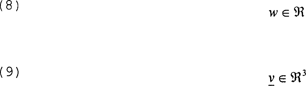
Für die Benutzung der Quaternionen gelten die Definitionen Gl. 10 bis Gl.15.For the use of the quaternions, the definitions Eq. 10 to Gl.15.
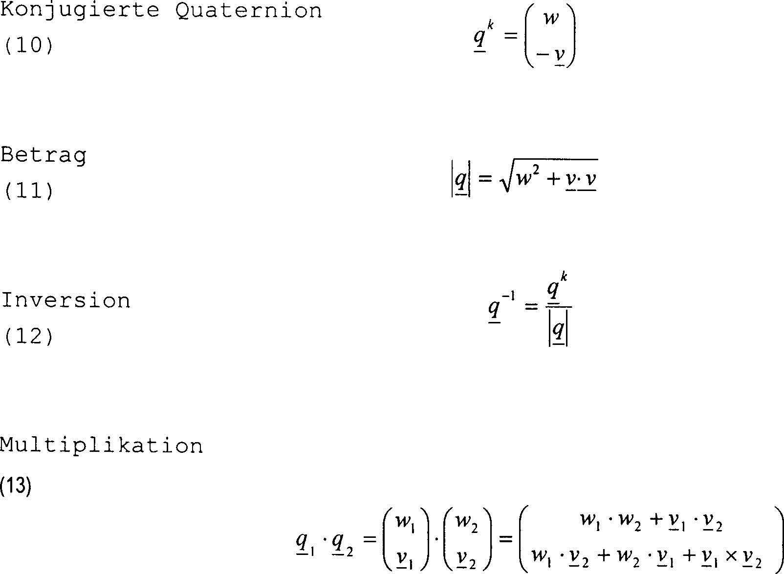

Besondere Bedeutung für die inertiale Objektverfolgung erhält die Multiplikation. Diese stellt eine Rotation einer Quaternion dar. Dafür wird eine Rotationsquaternion Gl.16. eingeführt.Of particular importance for the inertial Object tracking received the multiplication. This represents a rotation of a quaternion for that becomes a rotational quaternion Eq. 16. introduced.

Der Vektor ϕ besteht aus den einzelnen Drehungen um die Koordinatenachsen.The vector ϕ consists of the individual rotations around the coordinate axes.
Eine Drehung eines Punkts oder Vektors kann nun wie folgt errechnet werden. Zunächst müssen die Koordinaten des Punkts oder der Vektor mittels Gleichung Gl.14 in eine Quaternion umgewandelt und anschließend die Multiplikation mit der Rotationsquaternion durchgeführt werden (Gl.16.). Die Ergebnisquaternion enthält den rotierten Vektor in der gleichen Schreibweise. Unter der Voraussetzung, dass der Betrag einer Quaternion gleich eins ist, kann die invertierte Quaternion durch die konjugierte ersetzt werden (Gl.17).A rotation of a point or vector can now be calculated as follows. First, the coordinates of the point or the vector is converted into a quaternion using equation Eq. 14 and subsequently multiplication with the rotation quaternion (Gl.16.). The result quaternion contains the rotated vector in the same spelling. Provided that the amount a quaternion is one, the inverted quaternion be replaced by the conjugate (Eq.17).

Wie kann man diese Operation verdeutlichen?
Der Vektor ϕ ist der Normalenvektor zu der Ebene, in der
eine Drehung um den Winkel ½ϕ ausgeführt wird.
Der Winkel entspricht dem Betrag des Vektors ϕ. Siehe
Aus ![]()
![]()
Die konkrete Umsetzung des Quaternionen
Algorithmus ist in
Aus den Einheitsvektoren wird mit Hilfe von Gleichung Gl. 20 die Rotationsmatrix berechnet.The unit vectors become with Using equation Eq. 20 calculates the rotation matrix.

Ausgehend von einer Startorientierung des mit dem Objekt verbundenen Koordinatensystems, insbesondere ausgehend von sogenannten Einheitsstartvektoren, wird gemäß Gleichung 20 die Rctationsmatrix R, bei der es sich um eine 3×3-Matrix handelt, errechnet. Aus einer Umkehrung dieser Gleichung 20 lässt sich ein Rotationsquaternion qrot(k) erhalten. Mit Hilfe des Nullquaternions, welches sich aus den Nulleinheitsvektoren ergibt, wird durch eine Multiplikation mit dem Rotationsquaternion das Startquarternion berechnet. Bei der nächstfolgenden Abtastung, also bei der nächsten Messdatennahme und Integration zu aktuellen infinitesimalen Drehwinkeln A, B, C errechnet sich dann ein für diesen Schritt zu benutzendes Rotationsquaternion qrot(k). Das im vorherigen Schritt gebildete Quaternion qakt(k–1) wird dann mit diesem Rotationsquaternion qrot(k) gemäß Gleichung 13 multipliert um das aktuelle Quaternion des vorliegenden k-ten Schritts, nämlich qakt(k) zu erhalten. Aus diesem aktuellen Quaternion kann dann für den gerade durchgeführten Abtastschritt die aktuelle Orientierung des Objekts in beliebiger Darstellung angegeben werden.Starting from a start orientation of the coordinate system connected to the object, in particular starting from so-called unit start vectors, the reaction matrix R, which is a 3 × 3 matrix, is calculated in accordance with equation 20. A rotation quaternion q rot (k) can be obtained by reversing this equation 20. With the help of the zero quaternion, which results from the zero unit vectors, the starting quaternion is calculated by multiplying by the rotation quaternion. During the next subsequent scan, i.e. the next measurement data acquisition and integration at current infinitesimal angles of rotation A, B, C, a rotation quaternion q red (k) to be used for this step is then calculated. The quaternion q akt (k – 1) formed in the previous step is then multiplied by this rotation quaternion q rot (k) according to equation 13 in order to obtain the current quaternion of the present k-th step, namely q akt (k). From this current quaternion, the current orientation of the object can then be given in any representation for the scanning step just carried out.
Wenn vorausgehend davon die Rede ist, dass bei Ausführung des erfindungsgemäßen Verfahrens unter Verwendung von nur drei Drehratensensoren eine hohe Genauigkeit bei der Ermittlung der Orientierung des Objekts im Raum erreicht werden kann, und zwar über eine verhältnismäßig lange Zeitspanne im Bereich von einigen Minuten, insbesondere im Bereich von wenigstens 3, vorzugsweise von wenigstens 4 und in besonders bevorzugter Weise von wenigstens 5 min eine Abweichung von weniger als 4° erreicht werden kann, so bedeutet dies nicht, dass keine zusätzlichen Sensoren bei der Objektverfolgung zum Einsatz kommen dürfen. So erweist es sich, insbesondere bei Objektverfolgungsprozessen, die über einen Zeitraum von mehr als 5 min andauern, als vorteilhaft, wenn zusätzlich mittels Inertialsensoren die Erdbeschleunigung gemessen wird. Da die Erdbeschleunigung stets gleich gerichtet ist und an einem bestimmten Ort einen bestimmten Betrag aufweist, ist es möglich, hieraus in Kombination mit Magnetfeldsensoren (elektronischer Kompass) weitere Informationen zur Ermittlung der Orientierung des Objekts im Raum zu erhalten. Beispielsweise können hieraus auch translatorische Bewegungen errechnet werden.If it is said beforehand that when the method according to the invention is carried out using only three rotation rate sensors, high accuracy can be achieved in determining the orientation of the object in space, namely over a relatively long period of time in the range of a few minutes, in particular in the Range of at least 3, preferably at least 4 and in a particularly preferred manner of at least 5 min a deviation of less than 4 ° can be achieved, this does not mean that no additional sensors may be used for object tracking. It proves to be advantageous, particularly in the case of object tracking processes that last for a period of more than 5 minutes, if the acceleration of gravity is also measured by means of inertial sensors. Since the acceleration due to gravity is always the same and has a certain amount at a certain location, it is possible to obtain further information from this in combination with magnetic field sensors (electronic compass) for determining the orientation of the object in space. For example, translatory movements can also be calculated from this.
Es erweist sich als vorteilhaft, wenn zusätzlich mittels Kombination von Magnetfeldsensoren und Beschleunigungssensoren die Orientierung des Objekts im Raum ermittelt wird und mit der durch die drei Drehratensensoren ermittelten Orientierung verglichen wird. Da das Magnetfeld an einem bestimmten Ort auf der Erde richtungs- und betragsmäßig bekannt ist, kann durch Magnetfeldsensoren, vorzugsweise wenn die die Sensoren tragende Vorrichtung zur Ruhe gebracht wurde, die Orientierung der Vorrichtung im Raum sehr genau bestimmt werden. Es ist dann möglich, die hieraus gewonnene Orientierung mit derjenigen aus den Signalen der Drehratensensoren ermittelten Orientierung zu vergleichen und letztere entsprechend zu korrigieren.It turns out to be beneficial if additional using a combination of magnetic field sensors and acceleration sensors the orientation of the object in space is determined and with the compared by the orientation determined by the three rotation rate sensors becomes. Because the magnetic field at a certain location on Earth and known in terms of amount can by magnetic field sensors, preferably when the sensors bearing device was brought to rest, the orientation of the Device in the room can be determined very precisely. It is then possible that orientation obtained from this with that from the signals of the To compare the rotation rate sensors determined orientation and the latter correct accordingly.
In einer ganz besonders vorteilhaften Weiterbildung diese) Erfindungsgedankens werden die durch die Magnetfeldsensoren erhaltenen Signale auf eine mögliche Fehlerbehaftung untersucht, bevor sie bei der Ausführung der Objektverfolgung Verwendung finden. Auf diese Weise wird verhindert, dass ein durch eine Außeneinwirkung, etwa einen Stromstoß oder dergleichen, verursachtes fehlerhaftes Signal der Magnetfeldsensoren bei der Ausführung der Objektverfolgung Berücksichtigung findet. Die Signale der Magnetfeldsensoren können in vorteilhafter Weise im Hinblick auf ihren absoluten Wert hin untersucht werden. Wenn der absolute Wert der gemessenen Magnetfeldstärke den bekannten Wert des Erdmagnetfelds übersteigt, so kann hieraus geschlossen werden, dass diese Sensorsignale einen insbesondere durch Außeneinwirkung, etwa durch Annäherung eines Magneten, auftretenden Fehler enthalten und nicht berücksichtigt werden sollten. Des weiteren ist es denkbar und vorteilhaft, dass die Signale auf ihr Größenverhältnis und/oder die Orientierung zueinander untersucht werden. Auch anhand dessen lassen sich fehlerauslösende Einwirkungen detektieren, so dass die betreffenden Signale nicht berücksichtigt werden.In a particularly advantageous way Further development of this idea of the invention will be through the magnetic field sensors received signals on a possible Bugfixes are investigated before executing the Find object tracking. This prevents that one through an outside influence, like a surge or the like, caused incorrect signal of the magnetic field sensors in execution the object tracking place. The signals from the magnetic field sensors can advantageously be examined with regard to their absolute value. If the absolute value of the measured magnetic field strength the known value of the Earth's magnetic field exceeds it can be concluded from this that these sensor signals unite especially through external influences, about by approximation of a magnet, occurring errors and not taken into account should be. Furthermore, it is conceivable and advantageous that the signals on their size ratio and / or the orientation to each other are examined. Also based on that can cause errors Detect actions so that the signals in question are not considered become.
In besonders vorteilhafter Weise wäre es möglich, die Signale der Magnetfeldsensoren mit den Signalen von zusätzlich vorgesehenen Inertialsensoren zu vergleichen. Wenn, wie vorausgehend angedeutet, mittels Inertialsensoren die Erdbeschleunigung ermittelt wird, so ist es möglich, die Orientierung dieser Erdbeschleunigung mit der ebenfalls bekannten Orientierung der Magnetfeldstärke des Erdmagnetfelds zu vergleichen. Anhand dieses Vergleichs kann festgestellt werden, ob eine Störung vorliegt oder die aus den Werten ermittelte Orientierung des Objekts eine sehr genaue Orientierung darstellt.In a particularly advantageous manner would it be possible, the signals from the magnetic field sensors with the signals from additionally provided Compare inertial sensors. If, as indicated above, the gravitational acceleration is determined by means of inertial sensors, so Is it possible, the orientation of this gravitational acceleration with that also known Orientation of the magnetic field strength of the earth's magnetic field. Based on this comparison determine whether there is a malfunction or the orientation of the object determined from the values represents a very precise orientation.
Wenn die vorstehend erwähnte Untersuchung der Güte der Signale der Magnetfeldsensoren zu einem positiven Ergebnis führt und diese Signale, insbesondere zusätzlich die Signale der Inertialsensoren, als Stützinformation für die Ermittlung der tatsächlichen Orientierung des Objekts im Raum verwendet werden, so werden sie mit der aus den drei Drehratensensoren ermittelten Orientierung verglichen. Dieser Vergleich kann in vorteilhafter Weise unter Ausführung eines Kalman-Filter-Algorithmus durchgeführt werden.If the investigation mentioned above of goodness of the signals from the magnetic field sensors leads to a positive result and these signals, especially additional the signals from the inertial sensors, as support information for the determination the actual Orientation of the object to be used in space, so they will with the orientation determined from the three rotation rate sensors compared. This comparison can be carried out in an advantageous manner Kalman filter algorithm carried out become.
Hierbei erweist es sich als vorteilhaft, wenn die Messdaten sowohl der Inertialsensoren als auch der Magnetfeldsensoren während einer Ruhephase des Objekts genommen werden.It proves advantageous here if the measurement data of both the inertial sensors and the magnetic field sensors while be taken during a rest phase of the object.
Gegenstand der Erfindung ist, wie eingangs erwähnt, auch eine Vorrichtung zur Ausführung des erfindungsgemäßen Verfahrens mit den Merkmalen der Ansprüche 11 bis 15.The invention relates to how mentioned at the beginning, also a device for execution of the method according to the invention with the features of the claims 11 to 15.
Es wurde vorausgehend bereits darauf hingewiesen, dass das erfindungsgemäße Verfahren beziehungsweise eine erfindungsgemäße Vorrichtung beispielsweise bei Scannern Verwendung finden kann. Als besonders vorteilhaft erweist sich eine Verwendung im Bereich der Medizintechnik; es kann hiermit die Orientierung eines Ultraschallscannkopfs ermittelt werden, so dass beispielsweise ein sehr preiswerter zweidimensionaler Linienscanner verwendet werden kann, wobei der Scannkopf während der Ausführung des Scannvorgangs verschwenkt wird. Dieses Verschwenken kann dann über das erfindungsgemäße Verfahren festgestellt und ausgewertet werden. Auf diese Weise lässt sich ein sehr kostengünstiges Gerät darstellen, das gleichwohl dreidimensionale Informationen liefern kann.It was already followed up on it indicated that the inventive method or a device according to the invention can be used for example with scanners. As special Use in the field of medical technology proves to be advantageous; it can be used to determine the orientation of an ultrasound scanning head be, so for example a very inexpensive two-dimensional Line scanner can be used with the scanning head during the execution of the scanning process is pivoted. This pivoting can then over the inventive method be determined and evaluated. This way a very inexpensive Display device, that can still deliver three-dimensional information.
In der Produktionstechnik existiert beispielsweise die Problematik manuell geführte Geräte entweder zu navigieren oder jedenfalls den Ablauf eines Montage- oder Fertigungsprozesses zu überwachen. So wäre die Anwendung zur Schrauberpositionserfassung denkbar, um festzustellen oder zu Überwachen, ob an einer bestimmten Stelle eine bestimmte Anzahl von Umdrehungen ausgeführt wurde. Zum Beispiel könnte die Erfindung auch im Zusammenhang mit einer sogenannten Erdrakete, bei der es sich um ein selbstlaufendes Bohrsystem für Erdbohrungen handelt, verwendet werden. Solchenfalls erweist es sich als vorteilhaft, wenn zusätzlich zu den Drehratensensoren Beschleunigungsensoren vorgesehen sind, welche eine translatorische Bewegung der Erdrakete ermitteln. Somit kann jederzeit die Position und die Orientierung einer herkömmlichen Erdrakete während eines automatisch ablaufenden Bohrvorgangs ermittelt und zu weiteren Steuerungsprozessen verwendet werden.Exists in production technology For example, the problem of either manually navigating devices or in any case to monitor the course of an assembly or manufacturing process. That's how it would be Application for screwdriver position detection conceivable to determine or to monitor, whether at a certain point a certain number of revolutions accomplished has been. For example the invention also in connection with a so-called earth missile, which is a self-drilling drilling system for earth drilling acts, are used. In this case, it proves to be advantageous if additional acceleration sensors are provided for the rotation rate sensors, which determine a translational movement of the earth rocket. Consequently can always change the position and orientation of a conventional Earth rocket during of an automatically running drilling process and others Control processes are used.
Eine besonders vorteilhafte Anwendung für das erfindungsgemäße Verfahren und eine erfindungsgemäße Vorrichtung stellen sogenannte Bedienpulte beispielsweise für Roboter oder Modellflugzeuge oder -autos dar. Solche Bedienpulte werden vom Benutzer beispielsweise am Bauch abgestützt getragen. Wenn die Orientierung des Bedienpults kontinuierlich ermittelt wird, so lässt sich beispielsweise eine Drehung des Benutzers um 90° detektieren und zu Steuerungsprozessen verwenden. Beispielsweise ist es dann möglich, dass sich Steuerungsvorgänge, etwa eine Hebelbewegung am Bedienpult, welche den Roboter vom Benutzer wegbewegt, leicht erlernt und unabhängig von der Orientierung des Benutzers stets beibehalten werden kann. Das "links/rechts-Umdenken", das jedermann von der Fernsteuerung eines Spielzeugautos her bekannt ist, könnte dann entfallen.A particularly advantageous application for the method according to the invention and an inventive So-called control panels represent so-called control panels, for example for robots or model airplanes or cars. Such control panels are worn by the user, for example, on the stomach. If the orientation of the control panel is continuously determined, a rotation of the user by 90 ° can be detected and used for control processes, for example. For example, it is then possible for control processes, for example a lever movement on the control panel, which moves the robot away from the user, to be learned easily and always to be retained regardless of the orientation of the user. The "left / right rethinking" that everyone knows from the remote control of a toy car could then be dispensed with.
Des Weiteren könnte die Erfindung Verwendung in Form von miniaturisierten Orientierungserfassungssystemen auf dem Gebiet der medizinischen und orthopädischen Analyse finden.The invention could also be used in the form of miniaturized orientation detection systems in the field of medical and orthopedic analysis.
Beispielsweise könnten am Bein eines Benutzers an verschiedenen Stellen miniaturisierte Sensoranordnungen vorgesehen werden. Damit könnte eine Analyse des Bewegungsablaufs beim Benutzer durchgeführt werden und insbesondere Bewegungen der Körperteile zueinander detektiert werden.For example, on a user's leg miniaturized sensor arrangements are provided at various locations become. So that could an analysis of the movement sequence can be carried out at the user and in particular movements of the body parts to one another are detected become.
Weitere Merkmale, Einzelheiten und Vorteile der Erfindung ergeben sich aus den Patentansprüchen und der zeichnerischen Darstellung und nachfolgenden Beschreibung der Erfindung. In der Zeichnung zeigt:Other features, details and Advantages of the invention result from the claims and the graphic representation and the following description of the Invention. The drawing shows:
Die
Wie bereits erwähnt, wird zunächst das zu verfolgende Objekt, welches eine Vorrichtung mit drei Drehratensensoren trägt, im Raum zur Ruhe gebracht und derart mit einem ortsfesten Koordinatensystem referenziert, dass die aus den Signalen der drei Drehratensensoren ermittelten Winkel zunächst zu 0 gesetzt werden. Es wird dann während einer absoluten Ruhephase des Objekts und der das Objekt tragenden Sensoren ein Offset-Wert ermittelt, der bei jeder Abtastung, d. h. bei jeder Messdatennahme und Ermittlung von Drehwinkeln berücksichtigt wird. Es handelt sich hierbei um einen Driftvektor, dessen Komponenten die ermittelten Offset-Werte der Drehratensensoren umfassen.As already mentioned, this will be the first Object to be tracked, which is a device with three rotation rate sensors wearing, brought to rest in the room and so with a fixed coordinate system that references from the signals of the three rotation rate sensors determined angle first be set to 0. It then becomes during an absolute rest period of the object and the sensors carrying the object determines an offset value which on each scan, i.e. H. with every measurement data acquisition and determination of angles of rotation taken into account becomes. It is a drift vector, its components include the determined offset values of the rotation rate sensors.
Als ganz besonders vorteilhaft erweist es sich, dass erfindungsgemäß jedes mal, wenn ein Ruhen des Objekts detektiert und angenommen wird, die Offset-Werte der drei Drehratensensoren von neuem ermittelt und der weiteren Berechnung der Orientierung zugrundegelegt werden. Auf diese Weise lässt sich eine erhebliche Steigerung der Genauigkeit erreichen.Has proven to be particularly advantageous it according to the invention that each time when a resting of the object is detected and assumed the offset values of the three rotation rate sensors are determined anew and the basis for the further calculation of the orientation. That way achieve a significant increase in accuracy.
Ferner wird vor der Ausführung der Objektverfolgung die erwähnte Ausgleichsmatrix ermittelt, die einer Abweichung der drei Achsen der Drehratensensoren von einer angenommenen Orientierung zueinander und zu dem Objekt entspricht bzw. diese Abweichung genau ausgleichen soll.Furthermore, before the execution of the Object tracking the mentioned Compensation matrix determined that a deviation of the three axes the rotation rate sensors from an assumed orientation to each other and corresponds to the object or exactly compensate for this deviation should.
Bei der Ausführung der Objektverfolgung werden also zu aufeinanderfolgenden Zeitpunkten, etwa mit einer Abtastrate von 10 bis 30 Hz, insbesondere 20 Hz, die Sensorsignale der drei Drehratensensoren bei denen es sich um Winkelgeschwindigkeiten handelt, durch einfache Integration in infinitesimale Drehwinkel umgerechnet. Dabei wird aber die Ausgleichsmatrix sowie die Ermittlung des jeweiligen Offset-Werts der jeweiligen Sensoren berücksichtigt, um zu einer erhöhten Genauigkeit bei der Ermittlung der Orientierung zu gelangen.When executing object tracking are at successive times, for example with a Sampling rate of 10 to 30 Hz, especially 20 Hz, the sensor signals of the three rotation rate sensors which are angular speeds acts through simple integration into infinitesimal rotation angles converted. In doing so, however, the compensation matrix and the determination of the respective offset value of the respective sensors, in order to an elevated Accuracy in determining orientation.
Anhand der infinitesimal kleinen Winkeländerungen, die jeweils aus den Messsignalen der drei Drehratensensoren ermittelt wurden, könnte nun nach dem Eulerschen Verfahren durch Angabe von drei Winkeln die Orientierung des verdrehten Koordinatensystems des Objekts zum Referenzkoordinatensystem ermittelt werden. Stattdessen erweist es sich als vorteilhaft, wenn zur Ermittlung der Orientierung ein Quaternionen-Algorithmus der eingangs beschriebenen Art durchgeführt wird. Hierdurch kann anstelle von drei nacheinander auszuführenden Drehungen eine einzige Transformation angenommen werden, was die Genauigkeit der hieraus gewonnenen Orientierung des Objektsystems weiter erhöht.Based on the infinitesimally small Angle changes, which are determined from the measurement signals of the three rotation rate sensors could have been now according to Euler's method by specifying three angles Orientation of the twisted coordinate system of the object to the reference coordinate system be determined. Instead, it turns out to be beneficial if To determine the orientation, a quaternion algorithm of the one described at the beginning Kind of done becomes. This allows you to run three instead of three Twists a single transformation are assumed what the Accuracy of the orientation of the object system obtained from this further increased.
Im Ergebnis der Durchführung des Quaternionen-Algorithmus ist die Orientierung des Objekts im Raum gegeben.As a result of the implementation of the Quaternion algorithm is the orientation of the object in space given.
Diese Orientierung ergibt bei einer Abtastfrequenz von 15 – 25 Hz, insb. bei etwa 20 Hz nach 5 min. der Objektverfolgung eine Genauigkeit, die besser ist als 4° Abweichung. Diese Genauigkeit ist für viele Anwendungen ausreichend.This orientation results in a Sampling frequency from 15 - 25 Hz, especially at about 20 Hz after 5 min. object tracking accuracy, which is better than 4 ° deviation. This accuracy is for many applications sufficient.
Wie in
Des weiteren ist in
Claims (15)
Priority Applications (2)
| Application Number | Priority Date | Filing Date | Title |
|---|---|---|---|
| DE10312154A DE10312154B4 (en) | 2003-03-17 | 2003-03-17 | Method and apparatus for performing object tracking |
| EP04002975A EP1460378A3 (en) | 2003-03-17 | 2004-02-11 | Method and device for tracking an object |
Applications Claiming Priority (1)
| Application Number | Priority Date | Filing Date | Title |
|---|---|---|---|
| DE10312154A DE10312154B4 (en) | 2003-03-17 | 2003-03-17 | Method and apparatus for performing object tracking |
Publications (2)
| Publication Number | Publication Date |
|---|---|
| DE10312154A1 true DE10312154A1 (en) | 2004-06-17 |
| DE10312154B4 DE10312154B4 (en) | 2007-05-31 |
Family
ID=32319148
Family Applications (1)
| Application Number | Title | Priority Date | Filing Date |
|---|---|---|---|
| DE10312154A Expired - Fee Related DE10312154B4 (en) | 2003-03-17 | 2003-03-17 | Method and apparatus for performing object tracking |
Country Status (2)
| Country | Link |
|---|---|
| EP (1) | EP1460378A3 (en) |
| DE (1) | DE10312154B4 (en) |
Cited By (13)
| Publication number | Priority date | Publication date | Assignee | Title |
|---|---|---|---|---|
| FR2868281A1 (en) * | 2004-03-30 | 2005-10-07 | Commissariat Energie Atomique | METHOD FOR DETERMINING THE MOVEMENTS OF A PERSON |
| DE102004057959A1 (en) * | 2004-12-01 | 2006-06-08 | Fraunhofer-Gesellschaft zur Förderung der angewandten Forschung e.V. | Appliance to provide audio and/or video information to user, carried by user during operation, without limiting user's field of vision, while information to be provided depends on location and orientation of carried appliance relative |
| WO2006058633A1 (en) * | 2004-12-01 | 2006-06-08 | Fraunhofer-Gesellschaft zur Förderung der angewandten Forschung e.V. | Method and device for navigating and positioning an object relative to a patient |
| DE102006032127A1 (en) * | 2006-07-05 | 2008-01-10 | Aesculap Ag & Co. Kg | Method for calibrating position or orientation in area of surgical referencing unit of surgical navigation system, involves providing calibration unit, whose position or guideline data is assigned related to coordinate system |
| EP1881340A2 (en) | 2006-07-18 | 2008-01-23 | C. & E. FEIN GmbH | Position system for determining the position of a tool |
| DE102006052588A1 (en) | 2006-03-15 | 2008-09-25 | Mark Ital | Method for detecting acceleration of object or vehicle, involves detecting acceleration of object in quasi continuous manner corresponding to sample rate by two-dimensional inertial sensors |
| DE102007024157A1 (en) * | 2007-05-24 | 2009-07-02 | Siemens Ag | Machine tool operating device for e.g. machining workpiece, has joystick, where orientation of X-axis of joystick is perpendicular to orientation of machine axis during movement of machine element towards another machine axis |
| EP2078590A2 (en) | 2008-01-09 | 2009-07-15 | C. & E. FEIN GmbH | Screwing device and method for monitoring screwing processes |
| WO2010073044A1 (en) * | 2008-12-23 | 2010-07-01 | Oxford Brookes University | Gait monitor |
| DE102004046000B4 (en) * | 2004-09-17 | 2016-07-21 | C. & E. Fein Gmbh | Power tool with a position and orientation system |
| DE102015217449B3 (en) * | 2015-09-11 | 2016-12-29 | Dialog Semiconductor B.V. | Sensor combination method for determining the orientation of an object |
| DE102016206041A1 (en) | 2015-12-10 | 2017-06-14 | Robert Bosch Gmbh | Method for detecting misuse of an assembly tool |
| EP4008497A1 (en) * | 2020-12-04 | 2022-06-08 | Sick Ag | Validation of a pose of a robot |
Families Citing this family (3)
| Publication number | Priority date | Publication date | Assignee | Title |
|---|---|---|---|---|
| US8463569B2 (en) * | 2011-03-21 | 2013-06-11 | Caterpillar Trimble Control Technologies Llc | Method of operating a magnetic compass on a machine |
| CN102679976B (en) * | 2012-05-20 | 2014-07-09 | 西安费斯达自动化工程有限公司 | Aircraft quaternion revising model based on accelerated speed |
| CN103487050B (en) * | 2013-10-10 | 2015-12-02 | 哈尔滨工业大学 | A kind of Localization Approach for Indoor Mobile |
Citations (6)
| Publication number | Priority date | Publication date | Assignee | Title |
|---|---|---|---|---|
| DE3115215A1 (en) * | 1981-04-15 | 1982-11-11 | Teldix Gmbh, 6900 Heidelberg | Method for determining the instantaneous drift value of a course gyro |
| US5645077A (en) * | 1994-06-16 | 1997-07-08 | Massachusetts Institute Of Technology | Inertial orientation tracker apparatus having automatic drift compensation for tracking human head and other similarly sized body |
| US5906653A (en) * | 1995-12-01 | 1999-05-25 | Fujitsu Ten Limited | Navigation system and gyroscopic device |
| US5953683A (en) * | 1997-10-09 | 1999-09-14 | Ascension Technology Corporation | Sourceless orientation sensor |
| DE19937689A1 (en) * | 1998-08-11 | 2000-03-09 | Visteon Tech Llc | Determination of an output zero level of an angular velocity sensor |
| DE10110428A1 (en) * | 2001-03-05 | 2002-09-12 | Fraunhofer Ges Forschung | Method and device for performing object tracking |
Family Cites Families (4)
| Publication number | Priority date | Publication date | Assignee | Title |
|---|---|---|---|---|
| JPS6214212A (en) * | 1985-07-11 | 1987-01-22 | Toshiba Corp | Gyro guided unmanned carrying truck |
| US5795988A (en) * | 1996-07-01 | 1998-08-18 | Alliedsignal Inc. | Gyroscope noise reduction and drift compensation |
| US6421622B1 (en) * | 1998-06-05 | 2002-07-16 | Crossbow Technology, Inc. | Dynamic attitude measurement sensor and method |
| DE10132243C2 (en) * | 2001-07-04 | 2003-04-30 | Fraunhofer Ges Forschung | Wireless interaction system for virtual reality applications |
-
2003
- 2003-03-17 DE DE10312154A patent/DE10312154B4/en not_active Expired - Fee Related
-
2004
- 2004-02-11 EP EP04002975A patent/EP1460378A3/en not_active Withdrawn
Patent Citations (6)
| Publication number | Priority date | Publication date | Assignee | Title |
|---|---|---|---|---|
| DE3115215A1 (en) * | 1981-04-15 | 1982-11-11 | Teldix Gmbh, 6900 Heidelberg | Method for determining the instantaneous drift value of a course gyro |
| US5645077A (en) * | 1994-06-16 | 1997-07-08 | Massachusetts Institute Of Technology | Inertial orientation tracker apparatus having automatic drift compensation for tracking human head and other similarly sized body |
| US5906653A (en) * | 1995-12-01 | 1999-05-25 | Fujitsu Ten Limited | Navigation system and gyroscopic device |
| US5953683A (en) * | 1997-10-09 | 1999-09-14 | Ascension Technology Corporation | Sourceless orientation sensor |
| DE19937689A1 (en) * | 1998-08-11 | 2000-03-09 | Visteon Tech Llc | Determination of an output zero level of an angular velocity sensor |
| DE10110428A1 (en) * | 2001-03-05 | 2002-09-12 | Fraunhofer Ges Forschung | Method and device for performing object tracking |
Cited By (22)
| Publication number | Priority date | Publication date | Assignee | Title |
|---|---|---|---|---|
| FR2868281A1 (en) * | 2004-03-30 | 2005-10-07 | Commissariat Energie Atomique | METHOD FOR DETERMINING THE MOVEMENTS OF A PERSON |
| DE102004046000B4 (en) * | 2004-09-17 | 2016-07-21 | C. & E. Fein Gmbh | Power tool with a position and orientation system |
| DE102004057959A1 (en) * | 2004-12-01 | 2006-06-08 | Fraunhofer-Gesellschaft zur Förderung der angewandten Forschung e.V. | Appliance to provide audio and/or video information to user, carried by user during operation, without limiting user's field of vision, while information to be provided depends on location and orientation of carried appliance relative |
| WO2006058633A1 (en) * | 2004-12-01 | 2006-06-08 | Fraunhofer-Gesellschaft zur Förderung der angewandten Forschung e.V. | Method and device for navigating and positioning an object relative to a patient |
| DE102004057933A1 (en) * | 2004-12-01 | 2006-06-08 | Fraunhofer-Gesellschaft zur Förderung der angewandten Forschung e.V. | A method and apparatus for navigating and positioning an object relative to a patient |
| DE102004057959B4 (en) * | 2004-12-01 | 2010-03-18 | Fraunhofer-Gesellschaft zur Förderung der angewandten Forschung e.V. | Apparatus for conveying information to a user |
| DE102006052588A1 (en) | 2006-03-15 | 2008-09-25 | Mark Ital | Method for detecting acceleration of object or vehicle, involves detecting acceleration of object in quasi continuous manner corresponding to sample rate by two-dimensional inertial sensors |
| DE102006032127A1 (en) * | 2006-07-05 | 2008-01-10 | Aesculap Ag & Co. Kg | Method for calibrating position or orientation in area of surgical referencing unit of surgical navigation system, involves providing calibration unit, whose position or guideline data is assigned related to coordinate system |
| US7702477B2 (en) | 2006-07-05 | 2010-04-20 | Aesculap Ag | Calibration method and calibration device for a surgical referencing unit |
| DE102006032127B4 (en) * | 2006-07-05 | 2008-04-30 | Aesculap Ag & Co. Kg | Calibration method and calibration device for a surgical referencing unit |
| DE102006034270A1 (en) * | 2006-07-18 | 2008-01-24 | C. & E. Fein Gmbh | Location system for locating the position of a tool |
| EP1881340A2 (en) | 2006-07-18 | 2008-01-23 | C. & E. FEIN GmbH | Position system for determining the position of a tool |
| DE102007024157A1 (en) * | 2007-05-24 | 2009-07-02 | Siemens Ag | Machine tool operating device for e.g. machining workpiece, has joystick, where orientation of X-axis of joystick is perpendicular to orientation of machine axis during movement of machine element towards another machine axis |
| DE102007024157B4 (en) * | 2007-05-24 | 2010-09-16 | Siemens Ag | Machine tool with an operating device for operating the machine tool |
| EP2078590A2 (en) | 2008-01-09 | 2009-07-15 | C. & E. FEIN GmbH | Screwing device and method for monitoring screwing processes |
| DE102008004572A1 (en) | 2008-01-09 | 2009-07-16 | C. & E. Fein Gmbh | Screwing device and method for monitoring screwing operations |
| GB2467514A (en) * | 2008-12-23 | 2010-08-04 | Univ Oxford Brookes | Gait monitor for sensing vertical displacement |
| WO2010073044A1 (en) * | 2008-12-23 | 2010-07-01 | Oxford Brookes University | Gait monitor |
| US8868369B2 (en) | 2008-12-23 | 2014-10-21 | Oxford Brookes University | Gait monitor |
| DE102015217449B3 (en) * | 2015-09-11 | 2016-12-29 | Dialog Semiconductor B.V. | Sensor combination method for determining the orientation of an object |
| DE102016206041A1 (en) | 2015-12-10 | 2017-06-14 | Robert Bosch Gmbh | Method for detecting misuse of an assembly tool |
| EP4008497A1 (en) * | 2020-12-04 | 2022-06-08 | Sick Ag | Validation of a pose of a robot |
Also Published As
| Publication number | Publication date |
|---|---|
| EP1460378A2 (en) | 2004-09-22 |
| EP1460378A3 (en) | 2008-05-21 |
| DE10312154B4 (en) | 2007-05-31 |
Similar Documents
| Publication | Publication Date | Title |
|---|---|---|
| EP1817547B1 (en) | Method and device for navigating and positioning an object relative to a patient | |
| DE10312154B4 (en) | Method and apparatus for performing object tracking | |
| EP0557591B1 (en) | Device for determining the relative orientation of a body | |
| DE102007030784A1 (en) | Surveying device, has processor for calculating external orientation parameters of stereo images, which are produced by imaging device during straight and inverse views in dependent of position of their optical axis relative to target axis | |
| DE10228639A1 (en) | Long term inertial navigation method for vehicle in which two inertial navigation units are used with resulting state vectors combined to yield instantaneous vector value | |
| DE69733301T2 (en) | Sculling effect compensation in strapdown inertial navigation systems | |
| DE2755007A1 (en) | METHOD OF GEODAETIC SURVEYING | |
| DE3734064A1 (en) | DIRECTION SEARCHER FOR VEHICLES | |
| EP1094002A2 (en) | Satellite control system and method | |
| DE3436839A1 (en) | STEERING PROCESSOR | |
| EP1515159B1 (en) | Method for reducing the doppler centroid for coherent pulsed radar system | |
| EP1514799B1 (en) | Method for attitude determination of spacecraft using a direction vector and a total momentum measurement | |
| DE102014117277B4 (en) | carrier system | |
| DE2932468C1 (en) | Seeker head | |
| DE3438719A1 (en) | ARRANGEMENT FOR THE MUTUAL POSITION DETERMINATION OF MOTHER AND DAUGHTER INFRINGEMENT NAVIGATION SYSTEMS | |
| DD241471A1 (en) | METHOD AND ARRANGEMENT FOR THE AUTOMATIC CONTROL OF AIR IMAGE CAMERAS | |
| EP0557592B1 (en) | Device for calibrating a measuring device | |
| DE102004057959B4 (en) | Apparatus for conveying information to a user | |
| EP0276663A2 (en) | Device for determining the time variant position and the errors of a repeater navigation system relative to a master system | |
| DE102008058866B4 (en) | Device and method for determining the position of an object | |
| EP1270410A2 (en) | Method for determining the state parameters of a rigid body in space by using a videometer | |
| DE2734913C2 (en) | Target instruction device for target tracking devices | |
| WO2003038378A1 (en) | Navigation system for determining the course of a vehicle | |
| DE3111131A1 (en) | Operating method for a vehicle navigation device | |
| DE102004039379A1 (en) | Method and device for correcting systematic track signal errors of incremental position or rotary encoders |
Legal Events
| Date | Code | Title | Description |
|---|---|---|---|
| OAV | Publication of unexamined application with consent of applicant | ||
| OP8 | Request for examination as to paragraph 44 patent law | ||
| 8364 | No opposition during term of opposition | ||
| R119 | Application deemed withdrawn, or ip right lapsed, due to non-payment of renewal fee |