DE102013214144A1 - Diarylamino-substituted metal complexes - Google Patents
Diarylamino-substituted metal complexes Download PDFInfo
- Publication number
- DE102013214144A1 DE102013214144A1 DE102013214144.0A DE102013214144A DE102013214144A1 DE 102013214144 A1 DE102013214144 A1 DE 102013214144A1 DE 102013214144 A DE102013214144 A DE 102013214144A DE 102013214144 A1 DE102013214144 A1 DE 102013214144A1
- Authority
- DE
- Germany
- Prior art keywords
- complex
- group
- compound
- formula
- organic
- Prior art date
- Legal status (The legal status is an assumption and is not a legal conclusion. Google has not performed a legal analysis and makes no representation as to the accuracy of the status listed.)
- Granted
Links
- 229910052751 metal Inorganic materials 0.000 title description 23
- 239000002184 metal Substances 0.000 title description 23
- 125000001424 substituent group Chemical group 0.000 claims abstract description 24
- 125000001997 phenyl group Chemical group [H]C1=C([H])C([H])=C(*)C([H])=C1[H] 0.000 claims abstract description 18
- 238000006467 substitution reaction Methods 0.000 claims abstract description 18
- 239000010410 layer Substances 0.000 claims description 74
- 150000001875 compounds Chemical class 0.000 claims description 42
- -1 heteroalkenyl Chemical group 0.000 claims description 35
- 239000012044 organic layer Substances 0.000 claims description 25
- UJOBWOGCFQCDNV-UHFFFAOYSA-N 9H-carbazole Chemical compound C1=CC=C2C3=CC=CC=C3NC2=C1 UJOBWOGCFQCDNV-UHFFFAOYSA-N 0.000 claims description 20
- 125000000217 alkyl group Chemical group 0.000 claims description 20
- 125000003118 aryl group Chemical group 0.000 claims description 18
- YZCKVEUIGOORGS-OUBTZVSYSA-N Deuterium Chemical compound [2H] YZCKVEUIGOORGS-OUBTZVSYSA-N 0.000 claims description 16
- 229910052805 deuterium Inorganic materials 0.000 claims description 16
- 125000001072 heteroaryl group Chemical group 0.000 claims description 16
- UHOVQNZJYSORNB-UHFFFAOYSA-N Benzene Chemical compound C1=CC=CC=C1 UHOVQNZJYSORNB-UHFFFAOYSA-N 0.000 claims description 15
- 150000002431 hydrogen Chemical class 0.000 claims description 15
- 229910052739 hydrogen Inorganic materials 0.000 claims description 15
- 239000001257 hydrogen Substances 0.000 claims description 15
- 125000000753 cycloalkyl group Chemical group 0.000 claims description 13
- 239000002019 doping agent Substances 0.000 claims description 12
- YLQBMQCUIZJEEH-UHFFFAOYSA-N Furan Chemical compound C=1C=COC=1 YLQBMQCUIZJEEH-UHFFFAOYSA-N 0.000 claims description 10
- UFWIBTONFRDIAS-UHFFFAOYSA-N Naphthalene Chemical compound C1=CC=CC2=CC=CC=C21 UFWIBTONFRDIAS-UHFFFAOYSA-N 0.000 claims description 10
- YTPLMLYBLZKORZ-UHFFFAOYSA-N Thiophene Chemical compound C=1C=CSC=1 YTPLMLYBLZKORZ-UHFFFAOYSA-N 0.000 claims description 10
- ZUOUZKKEUPVFJK-UHFFFAOYSA-N diphenyl Chemical compound C1=CC=CC=C1C1=CC=CC=C1 ZUOUZKKEUPVFJK-UHFFFAOYSA-N 0.000 claims description 10
- 125000003342 alkenyl group Chemical group 0.000 claims description 9
- 125000000304 alkynyl group Chemical group 0.000 claims description 9
- XYFCBTPGUUZFHI-UHFFFAOYSA-N Phosphine Chemical compound P XYFCBTPGUUZFHI-UHFFFAOYSA-N 0.000 claims description 8
- 125000002252 acyl group Chemical group 0.000 claims description 8
- 125000003545 alkoxy group Chemical group 0.000 claims description 8
- 125000002915 carbonyl group Chemical group [*:2]C([*:1])=O 0.000 claims description 8
- 150000001735 carboxylic acids Chemical class 0.000 claims description 8
- 125000000392 cycloalkenyl group Chemical group 0.000 claims description 8
- 150000002148 esters Chemical class 0.000 claims description 8
- 229910052736 halogen Inorganic materials 0.000 claims description 8
- 150000002367 halogens Chemical class 0.000 claims description 8
- 125000004404 heteroalkyl group Chemical group 0.000 claims description 8
- 150000002527 isonitriles Chemical class 0.000 claims description 8
- 150000002825 nitriles Chemical class 0.000 claims description 8
- 125000000475 sulfinyl group Chemical group [*:2]S([*:1])=O 0.000 claims description 8
- 125000000472 sulfonyl group Chemical group *S(*)(=O)=O 0.000 claims description 8
- 125000003396 thiol group Chemical group [H]S* 0.000 claims description 8
- SLGBZMMZGDRARJ-UHFFFAOYSA-N Triphenylene Natural products C1=CC=C2C3=CC=CC=C3C3=CC=CC=C3C2=C1 SLGBZMMZGDRARJ-UHFFFAOYSA-N 0.000 claims description 7
- 125000004104 aryloxy group Chemical group 0.000 claims description 7
- 150000004696 coordination complex Chemical class 0.000 claims description 7
- 125000005580 triphenylene group Chemical group 0.000 claims description 7
- 125000003710 aryl alkyl group Chemical group 0.000 claims description 6
- 239000004305 biphenyl Substances 0.000 claims description 5
- 235000010290 biphenyl Nutrition 0.000 claims description 5
- 229910052799 carbon Inorganic materials 0.000 claims description 5
- 229930192474 thiophene Natural products 0.000 claims description 5
- 125000002496 methyl group Chemical group [H]C([H])([H])* 0.000 claims description 4
- 229910000073 phosphorus hydride Inorganic materials 0.000 claims description 4
- 125000004493 2-methylbut-1-yl group Chemical group CC(C*)CC 0.000 claims description 3
- 125000003542 3-methylbutan-2-yl group Chemical group [H]C([H])([H])C([H])(*)C([H])(C([H])([H])[H])C([H])([H])[H] 0.000 claims description 3
- 125000000484 butyl group Chemical group [H]C([*])([H])C([H])([H])C([H])([H])C([H])([H])[H] 0.000 claims description 3
- 125000000113 cyclohexyl group Chemical group [H]C1([H])C([H])([H])C([H])([H])C([H])(*)C([H])([H])C1([H])[H] 0.000 claims description 3
- 125000001511 cyclopentyl group Chemical group [H]C1([H])C([H])([H])C([H])([H])C([H])(*)C1([H])[H] 0.000 claims description 3
- 125000001495 ethyl group Chemical group [H]C([H])([H])C([H])([H])* 0.000 claims description 3
- 125000000959 isobutyl group Chemical group [H]C([H])([H])C([H])(C([H])([H])[H])C([H])([H])* 0.000 claims description 3
- 125000001972 isopentyl group Chemical group [H]C([H])([H])C([H])(C([H])([H])[H])C([H])([H])C([H])([H])* 0.000 claims description 3
- 125000001449 isopropyl group Chemical group [H]C([H])([H])C([H])(*)C([H])([H])[H] 0.000 claims description 3
- 125000001971 neopentyl group Chemical group [H]C([*])([H])C(C([H])([H])[H])(C([H])([H])[H])C([H])([H])[H] 0.000 claims description 3
- 125000001147 pentyl group Chemical group C(CCCC)* 0.000 claims description 3
- 125000001436 propyl group Chemical group [H]C([*])([H])C([H])([H])C([H])([H])[H] 0.000 claims description 3
- 125000002914 sec-butyl group Chemical group [H]C([H])([H])C([H])([H])C([H])(*)C([H])([H])[H] 0.000 claims description 3
- 125000003548 sec-pentyl group Chemical group [H]C([H])([H])C([H])([H])C([H])([H])C([H])(*)C([H])([H])[H] 0.000 claims description 3
- 125000001973 tert-pentyl group Chemical group [H]C([H])([H])C([H])([H])C(*)(C([H])([H])[H])C([H])([H])[H] 0.000 claims description 3
- OAICVXFJPJFONN-UHFFFAOYSA-N Phosphorus Chemical compound [P] OAICVXFJPJFONN-UHFFFAOYSA-N 0.000 claims 1
- 125000001181 organosilyl group Chemical group [SiH3]* 0.000 claims 1
- 239000000463 material Substances 0.000 abstract description 72
- 125000000609 carbazolyl group Chemical group C1(=CC=CC=2C3=CC=CC=C3NC12)* 0.000 abstract description 6
- 125000004986 diarylamino group Chemical group 0.000 abstract description 5
- VLKZOEOYAKHREP-UHFFFAOYSA-N n-Hexane Chemical class CCCCCC VLKZOEOYAKHREP-UHFFFAOYSA-N 0.000 description 43
- XEKOWRVHYACXOJ-UHFFFAOYSA-N Ethyl acetate Chemical compound CCOC(C)=O XEKOWRVHYACXOJ-UHFFFAOYSA-N 0.000 description 42
- YMWUJEATGCHHMB-UHFFFAOYSA-N Dichloromethane Chemical compound ClCCl YMWUJEATGCHHMB-UHFFFAOYSA-N 0.000 description 34
- IJGRMHOSHXDMSA-UHFFFAOYSA-N Atomic nitrogen Chemical compound N#N IJGRMHOSHXDMSA-UHFFFAOYSA-N 0.000 description 26
- 239000003446 ligand Substances 0.000 description 23
- VYPSYNLAJGMNEJ-UHFFFAOYSA-N Silicium dioxide Chemical compound O=[Si]=O VYPSYNLAJGMNEJ-UHFFFAOYSA-N 0.000 description 22
- LFQSCWFLJHTTHZ-UHFFFAOYSA-N Ethanol Chemical compound CCO LFQSCWFLJHTTHZ-UHFFFAOYSA-N 0.000 description 20
- 230000004888 barrier function Effects 0.000 description 18
- 229910052757 nitrogen Inorganic materials 0.000 description 18
- 239000007787 solid Substances 0.000 description 18
- 238000010992 reflux Methods 0.000 description 16
- LVTJOONKWUXEFR-FZRMHRINSA-N protoneodioscin Natural products O(C[C@@H](CC[C@]1(O)[C@H](C)[C@@H]2[C@]3(C)[C@H]([C@H]4[C@@H]([C@]5(C)C(=CC4)C[C@@H](O[C@@H]4[C@H](O[C@H]6[C@@H](O)[C@@H](O)[C@@H](O)[C@H](C)O6)[C@@H](O)[C@H](O[C@H]6[C@@H](O)[C@@H](O)[C@@H](O)[C@H](C)O6)[C@H](CO)O4)CC5)CC3)C[C@@H]2O1)C)[C@H]1[C@H](O)[C@H](O)[C@H](O)[C@@H](CO)O1 LVTJOONKWUXEFR-FZRMHRINSA-N 0.000 description 15
- 0 CC1(CC2=C(*(c3ccccc3)c(c(C)c3)c4)C=CCC2)*4c3-c2ccccc2C1(*)I(C1)(C1(*)c1ccccc1-c1*(C*)cccc1)=C Chemical compound CC1(CC2=C(*(c3ccccc3)c(c(C)c3)c4)C=CCC2)*4c3-c2ccccc2C1(*)I(C1)(C1(*)c1ccccc1-c1*(C*)cccc1)=C 0.000 description 14
- 239000000203 mixture Substances 0.000 description 14
- 238000002360 preparation method Methods 0.000 description 14
- 239000011541 reaction mixture Substances 0.000 description 14
- 239000000243 solution Substances 0.000 description 14
- 230000000052 comparative effect Effects 0.000 description 13
- VQGHOUODWALEFC-UHFFFAOYSA-N 2-phenylpyridine Chemical compound C1=CC=CC=C1C1=CC=CC=N1 VQGHOUODWALEFC-UHFFFAOYSA-N 0.000 description 11
- 238000006243 chemical reaction Methods 0.000 description 10
- 239000000047 product Substances 0.000 description 10
- 238000000034 method Methods 0.000 description 9
- XSCHRSMBECNVNS-UHFFFAOYSA-N quinoxaline Chemical compound N1=CC=NC2=CC=CC=C21 XSCHRSMBECNVNS-UHFFFAOYSA-N 0.000 description 9
- XLYOFNOQVPJJNP-UHFFFAOYSA-N water Substances O XLYOFNOQVPJJNP-UHFFFAOYSA-N 0.000 description 9
- 229910001868 water Inorganic materials 0.000 description 9
- 238000004770 highest occupied molecular orbital Methods 0.000 description 8
- 239000007924 injection Substances 0.000 description 8
- 238000002347 injection Methods 0.000 description 8
- 238000004768 lowest unoccupied molecular orbital Methods 0.000 description 8
- 239000002904 solvent Substances 0.000 description 8
- 239000000758 substrate Substances 0.000 description 8
- 230000005525 hole transport Effects 0.000 description 7
- 229910052760 oxygen Inorganic materials 0.000 description 7
- 239000000741 silica gel Substances 0.000 description 7
- 229910002027 silica gel Inorganic materials 0.000 description 7
- WEVYAHXRMPXWCK-UHFFFAOYSA-N Acetonitrile Chemical compound CC#N WEVYAHXRMPXWCK-UHFFFAOYSA-N 0.000 description 6
- OKKJLVBELUTLKV-UHFFFAOYSA-N Methanol Chemical compound OC OKKJLVBELUTLKV-UHFFFAOYSA-N 0.000 description 6
- DZBUGLKDJFMEHC-UHFFFAOYSA-N acridine Chemical compound C1=CC=CC2=CC3=CC=CC=C3N=C21 DZBUGLKDJFMEHC-UHFFFAOYSA-N 0.000 description 6
- IOJUPLGTWVMSFF-UHFFFAOYSA-N benzothiazole Chemical compound C1=CC=C2SC=NC2=C1 IOJUPLGTWVMSFF-UHFFFAOYSA-N 0.000 description 6
- 238000000151 deposition Methods 0.000 description 6
- RAXXELZNTBOGNW-UHFFFAOYSA-N imidazole Natural products C1=CNC=N1 RAXXELZNTBOGNW-UHFFFAOYSA-N 0.000 description 6
- AWJUIBRHMBBTKR-UHFFFAOYSA-N isoquinoline Chemical compound C1=NC=CC2=CC=CC=C21 AWJUIBRHMBBTKR-UHFFFAOYSA-N 0.000 description 6
- 239000011368 organic material Substances 0.000 description 6
- 239000000725 suspension Substances 0.000 description 6
- PCNDJXKNXGMECE-UHFFFAOYSA-N Phenazine Natural products C1=CC=CC2=NC3=CC=CC=C3N=C21 PCNDJXKNXGMECE-UHFFFAOYSA-N 0.000 description 5
- JUJWROOIHBZHMG-UHFFFAOYSA-N Pyridine Chemical group C1=CC=NC=C1 JUJWROOIHBZHMG-UHFFFAOYSA-N 0.000 description 5
- 239000012043 crude product Substances 0.000 description 5
- 239000000412 dendrimer Substances 0.000 description 5
- 229920000736 dendritic polymer Polymers 0.000 description 5
- 239000000706 filtrate Substances 0.000 description 5
- 229910052741 iridium Inorganic materials 0.000 description 5
- 230000005693 optoelectronics Effects 0.000 description 5
- 150000002894 organic compounds Chemical class 0.000 description 5
- 239000012071 phase Substances 0.000 description 5
- 229920000642 polymer Polymers 0.000 description 5
- 229910052717 sulfur Inorganic materials 0.000 description 5
- FCEHBMOGCRZNNI-UHFFFAOYSA-N 1-benzothiophene Chemical compound C1=CC=C2SC=CC2=C1 FCEHBMOGCRZNNI-UHFFFAOYSA-N 0.000 description 4
- PRNGIODVYLTUKH-UHFFFAOYSA-N 5-bromo-2-phenylpyridine Chemical compound N1=CC(Br)=CC=C1C1=CC=CC=C1 PRNGIODVYLTUKH-UHFFFAOYSA-N 0.000 description 4
- BBWBKWIROWJXMH-UHFFFAOYSA-N 5-iodo-4-methyl-2-phenylpyridine Chemical compound C1=C(I)C(C)=CC(C=2C=CC=CC=2)=N1 BBWBKWIROWJXMH-UHFFFAOYSA-N 0.000 description 4
- HTDYTHBVZCORKW-UHFFFAOYSA-N 9-(4-methyl-6-phenylpyridin-3-yl)carbazole Chemical compound N=1C=C(N2C3=CC=CC=C3C3=CC=CC=C32)C(C)=CC=1C1=CC=CC=C1 HTDYTHBVZCORKW-UHFFFAOYSA-N 0.000 description 4
- SIKJAQJRHWYJAI-UHFFFAOYSA-N Indole Chemical compound C1=CC=C2NC=CC2=C1 SIKJAQJRHWYJAI-UHFFFAOYSA-N 0.000 description 4
- KYQCOXFCLRTKLS-UHFFFAOYSA-N Pyrazine Chemical compound C1=CN=CC=N1 KYQCOXFCLRTKLS-UHFFFAOYSA-N 0.000 description 4
- SMWDFEZZVXVKRB-UHFFFAOYSA-N Quinoline Chemical compound N1=CC=CC2=CC=CC=C21 SMWDFEZZVXVKRB-UHFFFAOYSA-N 0.000 description 4
- XUIMIQQOPSSXEZ-UHFFFAOYSA-N Silicon Chemical compound [Si] XUIMIQQOPSSXEZ-UHFFFAOYSA-N 0.000 description 4
- MWPLVEDNUUSJAV-UHFFFAOYSA-N anthracene Chemical compound C1=CC=CC2=CC3=CC=CC=C3C=C21 MWPLVEDNUUSJAV-UHFFFAOYSA-N 0.000 description 4
- 125000006615 aromatic heterocyclic group Chemical group 0.000 description 4
- CUFNKYGDVFVPHO-UHFFFAOYSA-N azulene Chemical compound C1=CC=CC2=CC=CC2=C1 CUFNKYGDVFVPHO-UHFFFAOYSA-N 0.000 description 4
- 230000008901 benefit Effects 0.000 description 4
- MUALRAIOVNYAIW-UHFFFAOYSA-N binap Chemical compound C1=CC=CC=C1P(C=1C(=C2C=CC=CC2=CC=1)C=1C2=CC=CC=C2C=CC=1P(C=1C=CC=CC=1)C=1C=CC=CC=1)C1=CC=CC=C1 MUALRAIOVNYAIW-UHFFFAOYSA-N 0.000 description 4
- WDECIBYCCFPHNR-UHFFFAOYSA-N chrysene Chemical compound C1=CC=CC2=CC=C3C4=CC=CC=C4C=CC3=C21 WDECIBYCCFPHNR-UHFFFAOYSA-N 0.000 description 4
- 125000004122 cyclic group Chemical group 0.000 description 4
- TXCDCPKCNAJMEE-UHFFFAOYSA-N dibenzofuran Chemical compound C1=CC=C2C3=CC=CC=C3OC2=C1 TXCDCPKCNAJMEE-UHFFFAOYSA-N 0.000 description 4
- IYYZUPMFVPLQIF-UHFFFAOYSA-N dibenzothiophene Chemical compound C1=CC=C2C3=CC=CC=C3SC2=C1 IYYZUPMFVPLQIF-UHFFFAOYSA-N 0.000 description 4
- 229910001873 dinitrogen Inorganic materials 0.000 description 4
- DMBHHRLKUKUOEG-UHFFFAOYSA-N diphenylamine Chemical compound C=1C=CC=CC=1NC1=CC=CC=C1 DMBHHRLKUKUOEG-UHFFFAOYSA-N 0.000 description 4
- 239000003480 eluent Substances 0.000 description 4
- QIEABXIHCMILKG-UHFFFAOYSA-K iridium(3+);trifluoromethanesulfonate Chemical compound [Ir+3].[O-]S(=O)(=O)C(F)(F)F.[O-]S(=O)(=O)C(F)(F)F.[O-]S(=O)(=O)C(F)(F)F QIEABXIHCMILKG-UHFFFAOYSA-K 0.000 description 4
- IVSZLXZYQVIEFR-UHFFFAOYSA-N m-xylene Chemical group CC1=CC=CC(C)=C1 IVSZLXZYQVIEFR-UHFFFAOYSA-N 0.000 description 4
- GKIKPWYETKDHNQ-UHFFFAOYSA-N n,n,6-triphenylpyridin-3-amine Chemical compound C1=CC=CC=C1N(C=1C=NC(=CC=1)C=1C=CC=CC=1)C1=CC=CC=C1 GKIKPWYETKDHNQ-UHFFFAOYSA-N 0.000 description 4
- 125000004433 nitrogen atom Chemical group N* 0.000 description 4
- 239000003921 oil Substances 0.000 description 4
- NFHFRUOZVGFOOS-UHFFFAOYSA-N palladium;triphenylphosphane Chemical compound [Pd].C1=CC=CC=C1P(C=1C=CC=CC=1)C1=CC=CC=C1.C1=CC=CC=C1P(C=1C=CC=CC=1)C1=CC=CC=C1.C1=CC=CC=C1P(C=1C=CC=CC=1)C1=CC=CC=C1.C1=CC=CC=C1P(C=1C=CC=CC=1)C1=CC=CC=C1 NFHFRUOZVGFOOS-UHFFFAOYSA-N 0.000 description 4
- YNPNZTXNASCQKK-UHFFFAOYSA-N phenanthrene Chemical compound C1=CC=C2C3=CC=CC=C3C=CC2=C1 YNPNZTXNASCQKK-UHFFFAOYSA-N 0.000 description 4
- HXITXNWTGFUOAU-UHFFFAOYSA-N phenylboronic acid Chemical compound OB(O)C1=CC=CC=C1 HXITXNWTGFUOAU-UHFFFAOYSA-N 0.000 description 4
- FVZVCSNXTFCBQU-UHFFFAOYSA-N phosphanyl Chemical group [PH2] FVZVCSNXTFCBQU-UHFFFAOYSA-N 0.000 description 4
- 229910052698 phosphorus Inorganic materials 0.000 description 4
- BWHMMNNQKKPAPP-UHFFFAOYSA-L potassium carbonate Chemical compound [K+].[K+].[O-]C([O-])=O BWHMMNNQKKPAPP-UHFFFAOYSA-L 0.000 description 4
- BBEAQIROQSPTKN-UHFFFAOYSA-N pyrene Chemical compound C1=CC=C2C=CC3=CC=CC4=CC=C1C2=C43 BBEAQIROQSPTKN-UHFFFAOYSA-N 0.000 description 4
- 229910052710 silicon Inorganic materials 0.000 description 4
- MFRIHAYPQRLWNB-UHFFFAOYSA-N sodium tert-butoxide Chemical compound [Na+].CC(C)(C)[O-] MFRIHAYPQRLWNB-UHFFFAOYSA-N 0.000 description 4
- HPALAKNZSZLMCH-UHFFFAOYSA-M sodium;chloride;hydrate Chemical compound O.[Na+].[Cl-] HPALAKNZSZLMCH-UHFFFAOYSA-M 0.000 description 4
- RYHBNJHYFVUHQT-UHFFFAOYSA-N 1,4-Dioxane Chemical compound C1COCCO1 RYHBNJHYFVUHQT-UHFFFAOYSA-N 0.000 description 3
- FLBAYUMRQUHISI-UHFFFAOYSA-N 1,8-naphthyridine Chemical compound N1=CC=CC2=CC=CN=C21 FLBAYUMRQUHISI-UHFFFAOYSA-N 0.000 description 3
- WJFKNYWRSNBZNX-UHFFFAOYSA-N 10H-phenothiazine Chemical compound C1=CC=C2NC3=CC=CC=C3SC2=C1 WJFKNYWRSNBZNX-UHFFFAOYSA-N 0.000 description 3
- TZMSYXZUNZXBOL-UHFFFAOYSA-N 10H-phenoxazine Chemical compound C1=CC=C2NC3=CC=CC=C3OC2=C1 TZMSYXZUNZXBOL-UHFFFAOYSA-N 0.000 description 3
- VEPOHXYIFQMVHW-XOZOLZJESA-N 2,3-dihydroxybutanedioic acid (2S,3S)-3,4-dimethyl-2-phenylmorpholine Chemical compound OC(C(O)C(O)=O)C(O)=O.C[C@H]1[C@@H](OCCN1C)c1ccccc1 VEPOHXYIFQMVHW-XOZOLZJESA-N 0.000 description 3
- NUXIJRHGJXCNDZ-UHFFFAOYSA-N 5-bromo-4-methyl-2-phenylpyridine Chemical compound C1=C(Br)C(C)=CC(C=2C=CC=CC=2)=N1 NUXIJRHGJXCNDZ-UHFFFAOYSA-N 0.000 description 3
- GJCOSYZMQJWQCA-UHFFFAOYSA-N 9H-xanthene Chemical compound C1=CC=C2CC3=CC=CC=C3OC2=C1 GJCOSYZMQJWQCA-UHFFFAOYSA-N 0.000 description 3
- YXFVVABEGXRONW-UHFFFAOYSA-N Toluene Chemical compound CC1=CC=CC=C1 YXFVVABEGXRONW-UHFFFAOYSA-N 0.000 description 3
- 230000015572 biosynthetic process Effects 0.000 description 3
- 239000012267 brine Substances 0.000 description 3
- WCZVZNOTHYJIEI-UHFFFAOYSA-N cinnoline Chemical compound N1=NC=CC2=CC=CC=C21 WCZVZNOTHYJIEI-UHFFFAOYSA-N 0.000 description 3
- 239000003086 colorant Substances 0.000 description 3
- 238000004440 column chromatography Methods 0.000 description 3
- 229940125782 compound 2 Drugs 0.000 description 3
- 229940126214 compound 3 Drugs 0.000 description 3
- 229940125898 compound 5 Drugs 0.000 description 3
- VVVPGLRKXQSQSZ-UHFFFAOYSA-N indolo[3,2-c]carbazole Chemical class C1=CC=CC2=NC3=C4C5=CC=CC=C5N=C4C=CC3=C21 VVVPGLRKXQSQSZ-UHFFFAOYSA-N 0.000 description 3
- GKOZUEZYRPOHIO-UHFFFAOYSA-N iridium atom Chemical compound [Ir] GKOZUEZYRPOHIO-UHFFFAOYSA-N 0.000 description 3
- QDLAGTHXVHQKRE-UHFFFAOYSA-N lichenxanthone Natural products COC1=CC(O)=C2C(=O)C3=C(C)C=C(OC)C=C3OC2=C1 QDLAGTHXVHQKRE-UHFFFAOYSA-N 0.000 description 3
- 238000004020 luminiscence type Methods 0.000 description 3
- 230000007246 mechanism Effects 0.000 description 3
- 125000004430 oxygen atom Chemical group O* 0.000 description 3
- KDLHZDBZIXYQEI-UHFFFAOYSA-N palladium Substances [Pd] KDLHZDBZIXYQEI-UHFFFAOYSA-N 0.000 description 3
- 229950000688 phenothiazine Drugs 0.000 description 3
- LFSXCDWNBUNEEM-UHFFFAOYSA-N phthalazine Chemical compound C1=NN=CC2=CC=CC=C21 LFSXCDWNBUNEEM-UHFFFAOYSA-N 0.000 description 3
- 239000002244 precipitate Substances 0.000 description 3
- 230000008569 process Effects 0.000 description 3
- CPNGPNLZQNNVQM-UHFFFAOYSA-N pteridine Chemical compound N1=CN=CC2=NC=CN=C21 CPNGPNLZQNNVQM-UHFFFAOYSA-N 0.000 description 3
- 238000010898 silica gel chromatography Methods 0.000 description 3
- FVAUCKIRQBBSSJ-UHFFFAOYSA-M sodium iodide Chemical compound [Na+].[I-] FVAUCKIRQBBSSJ-UHFFFAOYSA-M 0.000 description 3
- 238000003786 synthesis reaction Methods 0.000 description 3
- 238000002207 thermal evaporation Methods 0.000 description 3
- JYEUMXHLPRZUAT-UHFFFAOYSA-N 1,2,3-triazine Chemical compound C1=CN=NN=C1 JYEUMXHLPRZUAT-UHFFFAOYSA-N 0.000 description 2
- KTZQTRPPVKQPFO-UHFFFAOYSA-N 1,2-benzoxazole Chemical compound C1=CC=C2C=NOC2=C1 KTZQTRPPVKQPFO-UHFFFAOYSA-N 0.000 description 2
- YJTKZCDBKVTVBY-UHFFFAOYSA-N 1,3-Diphenylbenzene Chemical group C1=CC=CC=C1C1=CC=CC(C=2C=CC=CC=2)=C1 YJTKZCDBKVTVBY-UHFFFAOYSA-N 0.000 description 2
- BCMCBBGGLRIHSE-UHFFFAOYSA-N 1,3-benzoxazole Chemical compound C1=CC=C2OC=NC2=C1 BCMCBBGGLRIHSE-UHFFFAOYSA-N 0.000 description 2
- BNRDGHFESOHOBF-UHFFFAOYSA-N 1-benzoselenophene Chemical compound C1=CC=C2[se]C=CC2=C1 BNRDGHFESOHOBF-UHFFFAOYSA-N 0.000 description 2
- HYZJCKYKOHLVJF-UHFFFAOYSA-N 1H-benzimidazole Chemical compound C1=CC=C2NC=NC2=C1 HYZJCKYKOHLVJF-UHFFFAOYSA-N 0.000 description 2
- BAXOFTOLAUCFNW-UHFFFAOYSA-N 1H-indazole Chemical compound C1=CC=C2C=NNC2=C1 BAXOFTOLAUCFNW-UHFFFAOYSA-N 0.000 description 2
- OLGGLCIDAMICTA-UHFFFAOYSA-N 2-pyridin-2-yl-1h-indole Chemical compound N1C2=CC=CC=C2C=C1C1=CC=CC=N1 OLGGLCIDAMICTA-UHFFFAOYSA-N 0.000 description 2
- QMEQBOSUJUOXMX-UHFFFAOYSA-N 2h-oxadiazine Chemical compound N1OC=CC=N1 QMEQBOSUJUOXMX-UHFFFAOYSA-N 0.000 description 2
- BCHZICNRHXRCHY-UHFFFAOYSA-N 2h-oxazine Chemical compound N1OC=CC=C1 BCHZICNRHXRCHY-UHFFFAOYSA-N 0.000 description 2
- BWCDLEQTELFBAW-UHFFFAOYSA-N 3h-dioxazole Chemical compound N1OOC=C1 BWCDLEQTELFBAW-UHFFFAOYSA-N 0.000 description 2
- SMADJLNFPGBTFY-UHFFFAOYSA-N 9-(6-phenylpyridin-3-yl)carbazole Chemical compound C1=CC=CC=C1C1=CC=C(N2C3=CC=CC=C3C3=CC=CC=C32)C=N1 SMADJLNFPGBTFY-UHFFFAOYSA-N 0.000 description 2
- ZOXJGFHDIHLPTG-UHFFFAOYSA-N Boron Chemical group [B] ZOXJGFHDIHLPTG-UHFFFAOYSA-N 0.000 description 2
- 238000006418 Brown reaction Methods 0.000 description 2
- 229940126062 Compound A Drugs 0.000 description 2
- 229910021595 Copper(I) iodide Inorganic materials 0.000 description 2
- NLDMNSXOCDLTTB-UHFFFAOYSA-N Heterophylliin A Natural products O1C2COC(=O)C3=CC(O)=C(O)C(O)=C3C3=C(O)C(O)=C(O)C=C3C(=O)OC2C(OC(=O)C=2C=C(O)C(O)=C(O)C=2)C(O)C1OC(=O)C1=CC(O)=C(O)C(O)=C1 NLDMNSXOCDLTTB-UHFFFAOYSA-N 0.000 description 2
- CSNNHWWHGAXBCP-UHFFFAOYSA-L Magnesium sulfate Chemical compound [Mg+2].[O-][S+2]([O-])([O-])[O-] CSNNHWWHGAXBCP-UHFFFAOYSA-L 0.000 description 2
- ZCQWOFVYLHDMMC-UHFFFAOYSA-N Oxazole Chemical compound C1=COC=N1 ZCQWOFVYLHDMMC-UHFFFAOYSA-N 0.000 description 2
- WTKZEGDFNFYCGP-UHFFFAOYSA-N Pyrazole Chemical compound C=1C=NNC=1 WTKZEGDFNFYCGP-UHFFFAOYSA-N 0.000 description 2
- CZPWVGJYEJSRLH-UHFFFAOYSA-N Pyrimidine Chemical compound C1=CN=CN=C1 CZPWVGJYEJSRLH-UHFFFAOYSA-N 0.000 description 2
- PMZURENOXWZQFD-UHFFFAOYSA-L Sodium Sulfate Chemical compound [Na+].[Na+].[O-]S([O-])(=O)=O PMZURENOXWZQFD-UHFFFAOYSA-L 0.000 description 2
- FZWLAAWBMGSTSO-UHFFFAOYSA-N Thiazole Chemical compound C1=CSC=N1 FZWLAAWBMGSTSO-UHFFFAOYSA-N 0.000 description 2
- FBVBNCGJVKIEHH-UHFFFAOYSA-N [1]benzofuro[3,2-b]pyridine Chemical compound C1=CN=C2C3=CC=CC=C3OC2=C1 FBVBNCGJVKIEHH-UHFFFAOYSA-N 0.000 description 2
- QZLAKPGRUFFNRD-UHFFFAOYSA-N [1]benzoselenolo[3,2-b]pyridine Chemical compound C1=CN=C2C3=CC=CC=C3[se]C2=C1 QZLAKPGRUFFNRD-UHFFFAOYSA-N 0.000 description 2
- WIUZHVZUGQDRHZ-UHFFFAOYSA-N [1]benzothiolo[3,2-b]pyridine Chemical compound C1=CN=C2C3=CC=CC=C3SC2=C1 WIUZHVZUGQDRHZ-UHFFFAOYSA-N 0.000 description 2
- 125000001931 aliphatic group Chemical group 0.000 description 2
- 150000004982 aromatic amines Chemical class 0.000 description 2
- RFRXIWQYSOIBDI-UHFFFAOYSA-N benzarone Chemical compound CCC=1OC2=CC=CC=C2C=1C(=O)C1=CC=C(O)C=C1 RFRXIWQYSOIBDI-UHFFFAOYSA-N 0.000 description 2
- 229910052796 boron Inorganic materials 0.000 description 2
- 125000004432 carbon atom Chemical group C* 0.000 description 2
- LSXDOTMGLUJQCM-UHFFFAOYSA-M copper(i) iodide Chemical compound I[Cu] LSXDOTMGLUJQCM-UHFFFAOYSA-M 0.000 description 2
- 230000008021 deposition Effects 0.000 description 2
- 238000010586 diagram Methods 0.000 description 2
- DHFABSXGNHDNCO-UHFFFAOYSA-N dibenzoselenophene Chemical compound C1=CC=C2C3=CC=CC=C3[se]C2=C1 DHFABSXGNHDNCO-UHFFFAOYSA-N 0.000 description 2
- SPWVRYZQLGQKGK-UHFFFAOYSA-N dichloromethane;hexane Chemical compound ClCCl.CCCCCC SPWVRYZQLGQKGK-UHFFFAOYSA-N 0.000 description 2
- GVEPBJHOBDJJJI-UHFFFAOYSA-N fluoranthrene Natural products C1=CC(C2=CC=CC=C22)=C3C2=CC=CC3=C1 GVEPBJHOBDJJJI-UHFFFAOYSA-N 0.000 description 2
- RMBPEFMHABBEKP-UHFFFAOYSA-N fluorene Chemical compound C1=CC=C2C3=C[CH]C=CC3=CC2=C1 RMBPEFMHABBEKP-UHFFFAOYSA-N 0.000 description 2
- JVZRCNQLWOELDU-UHFFFAOYSA-N gamma-Phenylpyridine Natural products C1=CC=CC=C1C1=CC=NC=C1 JVZRCNQLWOELDU-UHFFFAOYSA-N 0.000 description 2
- 125000005843 halogen group Chemical group 0.000 description 2
- PZOUSPYUWWUPPK-UHFFFAOYSA-N indole Natural products CC1=CC=CC2=C1C=CN2 PZOUSPYUWWUPPK-UHFFFAOYSA-N 0.000 description 2
- RKJUIXBNRJVNHR-UHFFFAOYSA-N indolenine Natural products C1=CC=C2CC=NC2=C1 RKJUIXBNRJVNHR-UHFFFAOYSA-N 0.000 description 2
- 229960005544 indolocarbazole Drugs 0.000 description 2
- 150000002503 iridium Chemical class 0.000 description 2
- 238000004519 manufacturing process Methods 0.000 description 2
- 239000011159 matrix material Substances 0.000 description 2
- HZVOZRGWRWCICA-UHFFFAOYSA-N methanediyl Chemical compound [CH2] HZVOZRGWRWCICA-UHFFFAOYSA-N 0.000 description 2
- IBHBKWKFFTZAHE-UHFFFAOYSA-N n-[4-[4-(n-naphthalen-1-ylanilino)phenyl]phenyl]-n-phenylnaphthalen-1-amine Chemical group C1=CC=CC=C1N(C=1C2=CC=CC=C2C=CC=1)C1=CC=C(C=2C=CC(=CC=2)N(C=2C=CC=CC=2)C=2C3=CC=CC=C3C=CC=2)C=C1 IBHBKWKFFTZAHE-UHFFFAOYSA-N 0.000 description 2
- NIHNNTQXNPWCJQ-UHFFFAOYSA-N o-biphenylenemethane Natural products C1=CC=C2CC3=CC=CC=C3C2=C1 NIHNNTQXNPWCJQ-UHFFFAOYSA-N 0.000 description 2
- 239000012074 organic phase Substances 0.000 description 2
- WCPAKWJPBJAGKN-UHFFFAOYSA-N oxadiazole Chemical compound C1=CON=N1 WCPAKWJPBJAGKN-UHFFFAOYSA-N 0.000 description 2
- AZHVQJLDOFKHPZ-UHFFFAOYSA-N oxathiazine Chemical compound O1SN=CC=C1 AZHVQJLDOFKHPZ-UHFFFAOYSA-N 0.000 description 2
- CQDAMYNQINDRQC-UHFFFAOYSA-N oxatriazole Chemical compound C1=NN=NO1 CQDAMYNQINDRQC-UHFFFAOYSA-N 0.000 description 2
- AICOOMRHRUFYCM-ZRRPKQBOSA-N oxazine, 1 Chemical compound C([C@@H]1[C@H](C(C[C@]2(C)[C@@H]([C@H](C)N(C)C)[C@H](O)C[C@]21C)=O)CC1=CC2)C[C@H]1[C@@]1(C)[C@H]2N=C(C(C)C)OC1 AICOOMRHRUFYCM-ZRRPKQBOSA-N 0.000 description 2
- 238000000059 patterning Methods 0.000 description 2
- 125000002080 perylenyl group Chemical group C1(=CC=C2C=CC=C3C4=CC=CC5=CC=CC(C1=C23)=C45)* 0.000 description 2
- CSHWQDPOILHKBI-UHFFFAOYSA-N peryrene Natural products C1=CC(C2=CC=CC=3C2=C2C=CC=3)=C3C2=CC=CC3=C1 CSHWQDPOILHKBI-UHFFFAOYSA-N 0.000 description 2
- 125000004437 phosphorous atom Chemical group 0.000 description 2
- 229910052697 platinum Inorganic materials 0.000 description 2
- 229910000027 potassium carbonate Inorganic materials 0.000 description 2
- 239000011241 protective layer Substances 0.000 description 2
- 238000000746 purification Methods 0.000 description 2
- PBMFSQRYOILNGV-UHFFFAOYSA-N pyridazine Chemical compound C1=CC=NN=C1 PBMFSQRYOILNGV-UHFFFAOYSA-N 0.000 description 2
- UMJSCPRVCHMLSP-UHFFFAOYSA-N pyridine Natural products COC1=CC=CN=C1 UMJSCPRVCHMLSP-UHFFFAOYSA-N 0.000 description 2
- JWVCLYRUEFBMGU-UHFFFAOYSA-N quinazoline Chemical compound N1=CN=CC2=CC=CC=C21 JWVCLYRUEFBMGU-UHFFFAOYSA-N 0.000 description 2
- 229920006395 saturated elastomer Polymers 0.000 description 2
- 239000010703 silicon Substances 0.000 description 2
- 239000002356 single layer Substances 0.000 description 2
- 229910052938 sodium sulfate Inorganic materials 0.000 description 2
- 235000011152 sodium sulphate Nutrition 0.000 description 2
- 238000000859 sublimation Methods 0.000 description 2
- 230000008022 sublimation Effects 0.000 description 2
- 239000000126 substance Substances 0.000 description 2
- 125000004434 sulfur atom Chemical group 0.000 description 2
- VLLMWSRANPNYQX-UHFFFAOYSA-N thiadiazole Chemical compound C1=CSN=N1.C1=CSN=N1 VLLMWSRANPNYQX-UHFFFAOYSA-N 0.000 description 2
- 150000003852 triazoles Chemical class 0.000 description 2
- LWIHDJKSTIGBAC-UHFFFAOYSA-K tripotassium phosphate Chemical compound [K+].[K+].[K+].[O-]P([O-])([O-])=O LWIHDJKSTIGBAC-UHFFFAOYSA-K 0.000 description 2
- JRHPOFJADXHYBR-OCAPTIKFSA-N (1r,2s)-1-n,2-n-dimethylcyclohexane-1,2-diamine Chemical compound CN[C@@H]1CCCC[C@@H]1NC JRHPOFJADXHYBR-OCAPTIKFSA-N 0.000 description 1
- BUHVIAUBTBOHAG-FOYDDCNASA-N (2r,3r,4s,5r)-2-[6-[[2-(3,5-dimethoxyphenyl)-2-(2-methylphenyl)ethyl]amino]purin-9-yl]-5-(hydroxymethyl)oxolane-3,4-diol Chemical compound COC1=CC(OC)=CC(C(CNC=2C=3N=CN(C=3N=CN=2)[C@H]2[C@@H]([C@H](O)[C@@H](CO)O2)O)C=2C(=CC=CC=2)C)=C1 BUHVIAUBTBOHAG-FOYDDCNASA-N 0.000 description 1
- JRHPOFJADXHYBR-UHFFFAOYSA-N 1-n,2-n-dimethylcyclohexane-1,2-diamine Chemical compound CNC1CCCCC1NC JRHPOFJADXHYBR-UHFFFAOYSA-N 0.000 description 1
- WWJLJUAHQHXDGM-UHFFFAOYSA-N 2,5-dibromo-4-methylpyridine Chemical compound CC1=CC(Br)=NC=C1Br WWJLJUAHQHXDGM-UHFFFAOYSA-N 0.000 description 1
- ZNQVEEAIQZEUHB-UHFFFAOYSA-N 2-ethoxyethanol Chemical compound CCOCCO ZNQVEEAIQZEUHB-UHFFFAOYSA-N 0.000 description 1
- 150000005360 2-phenylpyridines Chemical class 0.000 description 1
- AJZDHLHTTJRNQJ-UHFFFAOYSA-N 3-[4-(aminomethyl)-6-(trifluoromethyl)pyridin-2-yl]oxy-N-[2-(tetrazol-1-yl)ethyl]benzamide Chemical compound N1(N=NN=C1)CCNC(C1=CC(=CC=C1)OC1=NC(=CC(=C1)CN)C(F)(F)F)=O AJZDHLHTTJRNQJ-UHFFFAOYSA-N 0.000 description 1
- BWGRDBSNKQABCB-UHFFFAOYSA-N 4,4-difluoro-N-[3-[3-(3-methyl-5-propan-2-yl-1,2,4-triazol-4-yl)-8-azabicyclo[3.2.1]octan-8-yl]-1-thiophen-2-ylpropyl]cyclohexane-1-carboxamide Chemical compound CC(C)C1=NN=C(C)N1C1CC2CCC(C1)N2CCC(NC(=O)C1CCC(F)(F)CC1)C1=CC=CS1 BWGRDBSNKQABCB-UHFFFAOYSA-N 0.000 description 1
- DIVZFUBWFAOMCW-UHFFFAOYSA-N 4-n-(3-methylphenyl)-1-n,1-n-bis[4-(n-(3-methylphenyl)anilino)phenyl]-4-n-phenylbenzene-1,4-diamine Chemical group CC1=CC=CC(N(C=2C=CC=CC=2)C=2C=CC(=CC=2)N(C=2C=CC(=CC=2)N(C=2C=CC=CC=2)C=2C=C(C)C=CC=2)C=2C=CC(=CC=2)N(C=2C=CC=CC=2)C=2C=C(C)C=CC=2)=C1 DIVZFUBWFAOMCW-UHFFFAOYSA-N 0.000 description 1
- HSNBRDZXJMPDGH-UHFFFAOYSA-N 5-bromo-2-iodopyridine Chemical compound BrC1=CC=C(I)N=C1 HSNBRDZXJMPDGH-UHFFFAOYSA-N 0.000 description 1
- NLXLAEXVIDQMFP-UHFFFAOYSA-N Ammonia chloride Chemical class [NH4+].[Cl-] NLXLAEXVIDQMFP-UHFFFAOYSA-N 0.000 description 1
- HMDSHIZGTPRJHT-BRFYHDHCSA-N CC(CCCC1)[C@@H]1NC Chemical compound CC(CCCC1)[C@@H]1NC HMDSHIZGTPRJHT-BRFYHDHCSA-N 0.000 description 1
- 239000004593 Epoxy Substances 0.000 description 1
- DGAQECJNVWCQMB-PUAWFVPOSA-M Ilexoside XXIX Chemical compound C[C@@H]1CC[C@@]2(CC[C@@]3(C(=CC[C@H]4[C@]3(CC[C@@H]5[C@@]4(CC[C@@H](C5(C)C)OS(=O)(=O)[O-])C)C)[C@@H]2[C@]1(C)O)C)C(=O)O[C@H]6[C@@H]([C@H]([C@@H]([C@H](O6)CO)O)O)O.[Na+] DGAQECJNVWCQMB-PUAWFVPOSA-M 0.000 description 1
- 229910021638 Iridium(III) chloride Inorganic materials 0.000 description 1
- LFZAGIJXANFPFN-UHFFFAOYSA-N N-[3-[4-(3-methyl-5-propan-2-yl-1,2,4-triazol-4-yl)piperidin-1-yl]-1-thiophen-2-ylpropyl]acetamide Chemical compound C(C)(C)C1=NN=C(N1C1CCN(CC1)CCC(C=1SC=CC=1)NC(C)=O)C LFZAGIJXANFPFN-UHFFFAOYSA-N 0.000 description 1
- CTQNGGLPUBDAKN-UHFFFAOYSA-N O-Xylene Chemical compound CC1=CC=CC=C1C CTQNGGLPUBDAKN-UHFFFAOYSA-N 0.000 description 1
- ABLZXFCXXLZCGV-UHFFFAOYSA-N Phosphorous acid Chemical compound OP(O)=O ABLZXFCXXLZCGV-UHFFFAOYSA-N 0.000 description 1
- 229920001609 Poly(3,4-ethylenedioxythiophene) Polymers 0.000 description 1
- 238000013459 approach Methods 0.000 description 1
- 239000008346 aqueous phase Substances 0.000 description 1
- 239000012298 atmosphere Substances 0.000 description 1
- 230000000903 blocking effect Effects 0.000 description 1
- 238000009835 boiling Methods 0.000 description 1
- 238000005229 chemical vapour deposition Methods 0.000 description 1
- 239000012230 colorless oil Substances 0.000 description 1
- 230000000295 complement effect Effects 0.000 description 1
- 229940125904 compound 1 Drugs 0.000 description 1
- 229920001940 conductive polymer Polymers 0.000 description 1
- 230000021615 conjugation Effects 0.000 description 1
- 239000013058 crude material Substances 0.000 description 1
- 239000010779 crude oil Substances 0.000 description 1
- 239000002178 crystalline material Substances 0.000 description 1
- 238000005137 deposition process Methods 0.000 description 1
- 238000013461 design Methods 0.000 description 1
- 125000005266 diarylamine group Chemical group 0.000 description 1
- 230000000694 effects Effects 0.000 description 1
- 238000010828 elution Methods 0.000 description 1
- 238000005516 engineering process Methods 0.000 description 1
- 238000001704 evaporation Methods 0.000 description 1
- 230000008020 evaporation Effects 0.000 description 1
- 239000012065 filter cake Substances 0.000 description 1
- 230000010006 flight Effects 0.000 description 1
- 239000006260 foam Substances 0.000 description 1
- 125000000524 functional group Chemical group 0.000 description 1
- 239000007789 gas Substances 0.000 description 1
- 239000011521 glass Substances 0.000 description 1
- 125000000623 heterocyclic group Chemical group 0.000 description 1
- 125000004435 hydrogen atom Chemical group [H]* 0.000 description 1
- AMGQUBHHOARCQH-UHFFFAOYSA-N indium;oxotin Chemical compound [In].[Sn]=O AMGQUBHHOARCQH-UHFFFAOYSA-N 0.000 description 1
- 150000002484 inorganic compounds Chemical class 0.000 description 1
- HSMVBWVJFOZSJI-UHFFFAOYSA-K iridium(3+) 2-phenylpyridine trifluoromethanesulfonate Chemical compound [Ir+3].[O-]S(=O)(=O)C(F)(F)F.[O-]S(=O)(=O)C(F)(F)F.[O-]S(=O)(=O)C(F)(F)F.C1=CC=CC=C1C1=CC=CC=N1 HSMVBWVJFOZSJI-UHFFFAOYSA-K 0.000 description 1
- RTRAMYYYHJZWQK-UHFFFAOYSA-N iridium;2-phenylpyridine Chemical compound [Ir].C1=CC=CC=C1C1=CC=CC=N1 RTRAMYYYHJZWQK-UHFFFAOYSA-N 0.000 description 1
- UEEXRMUCXBPYOV-UHFFFAOYSA-N iridium;2-phenylpyridine Chemical group [Ir].C1=CC=CC=C1C1=CC=CC=N1.C1=CC=CC=C1C1=CC=CC=N1.C1=CC=CC=C1C1=CC=CC=N1 UEEXRMUCXBPYOV-UHFFFAOYSA-N 0.000 description 1
- 239000007788 liquid Substances 0.000 description 1
- 239000011777 magnesium Substances 0.000 description 1
- 229910052943 magnesium sulfate Inorganic materials 0.000 description 1
- 235000019341 magnesium sulphate Nutrition 0.000 description 1
- 229910044991 metal oxide Inorganic materials 0.000 description 1
- 150000004706 metal oxides Chemical class 0.000 description 1
- 239000000178 monomer Substances 0.000 description 1
- 239000012299 nitrogen atmosphere Substances 0.000 description 1
- 239000003960 organic solvent Substances 0.000 description 1
- 229910052762 osmium Inorganic materials 0.000 description 1
- 230000003647 oxidation Effects 0.000 description 1
- 238000007254 oxidation reaction Methods 0.000 description 1
- IEQIEDJGQAUEQZ-UHFFFAOYSA-N phthalocyanine Chemical compound N1C(N=C2C3=CC=CC=C3C(N=C3C4=CC=CC=C4C(=N4)N3)=N2)=C(C=CC=C2)C2=C1N=C1C2=CC=CC=C2C4=N1 IEQIEDJGQAUEQZ-UHFFFAOYSA-N 0.000 description 1
- 229910000160 potassium phosphate Inorganic materials 0.000 description 1
- 235000011009 potassium phosphates Nutrition 0.000 description 1
- 125000004076 pyridyl group Chemical group 0.000 description 1
- 238000009877 rendering Methods 0.000 description 1
- 238000011160 research Methods 0.000 description 1
- 238000004366 reverse phase liquid chromatography Methods 0.000 description 1
- 238000000926 separation method Methods 0.000 description 1
- 230000011664 signaling Effects 0.000 description 1
- 150000004756 silanes Chemical class 0.000 description 1
- QRUBYZBWAOOHSV-UHFFFAOYSA-M silver trifluoromethanesulfonate Chemical compound [Ag+].[O-]S(=O)(=O)C(F)(F)F QRUBYZBWAOOHSV-UHFFFAOYSA-M 0.000 description 1
- 150000003384 small molecules Chemical class 0.000 description 1
- 239000011734 sodium Substances 0.000 description 1
- 229910052708 sodium Inorganic materials 0.000 description 1
- 235000009518 sodium iodide Nutrition 0.000 description 1
- 238000004528 spin coating Methods 0.000 description 1
- 239000007858 starting material Substances 0.000 description 1
- 230000000153 supplemental effect Effects 0.000 description 1
- 238000012360 testing method Methods 0.000 description 1
- DANYXEHCMQHDNX-UHFFFAOYSA-K trichloroiridium Chemical compound Cl[Ir](Cl)Cl DANYXEHCMQHDNX-UHFFFAOYSA-K 0.000 description 1
- ITMCEJHCFYSIIV-UHFFFAOYSA-M triflate Chemical compound [O-]S(=O)(=O)C(F)(F)F ITMCEJHCFYSIIV-UHFFFAOYSA-M 0.000 description 1
- 238000007740 vapor deposition Methods 0.000 description 1
- 239000003981 vehicle Substances 0.000 description 1
- 238000005406 washing Methods 0.000 description 1
- 238000003466 welding Methods 0.000 description 1
- 239000008096 xylene Substances 0.000 description 1
- 229910052725 zinc Inorganic materials 0.000 description 1
Images


Classifications
-
- C—CHEMISTRY; METALLURGY
- C07—ORGANIC CHEMISTRY
- C07D—HETEROCYCLIC COMPOUNDS
- C07D213/00—Heterocyclic compounds containing six-membered rings, not condensed with other rings, with one nitrogen atom as the only ring hetero atom and three or more double bonds between ring members or between ring members and non-ring members
- C07D213/02—Heterocyclic compounds containing six-membered rings, not condensed with other rings, with one nitrogen atom as the only ring hetero atom and three or more double bonds between ring members or between ring members and non-ring members having three double bonds between ring members or between ring members and non-ring members
- C07D213/04—Heterocyclic compounds containing six-membered rings, not condensed with other rings, with one nitrogen atom as the only ring hetero atom and three or more double bonds between ring members or between ring members and non-ring members having three double bonds between ring members or between ring members and non-ring members having no bond between the ring nitrogen atom and a non-ring member or having only hydrogen or carbon atoms directly attached to the ring nitrogen atom
- C07D213/60—Heterocyclic compounds containing six-membered rings, not condensed with other rings, with one nitrogen atom as the only ring hetero atom and three or more double bonds between ring members or between ring members and non-ring members having three double bonds between ring members or between ring members and non-ring members having no bond between the ring nitrogen atom and a non-ring member or having only hydrogen or carbon atoms directly attached to the ring nitrogen atom with hetero atoms or with carbon atoms having three bonds to hetero atoms with at the most one bond to halogen, e.g. ester or nitrile radicals, directly attached to ring carbon atoms
- C07D213/72—Nitrogen atoms
- C07D213/74—Amino or imino radicals substituted by hydrocarbon or substituted hydrocarbon radicals
-
- C—CHEMISTRY; METALLURGY
- C07—ORGANIC CHEMISTRY
- C07F—ACYCLIC, CARBOCYCLIC OR HETEROCYCLIC COMPOUNDS CONTAINING ELEMENTS OTHER THAN CARBON, HYDROGEN, HALOGEN, OXYGEN, NITROGEN, SULFUR, SELENIUM OR TELLURIUM
- C07F15/00—Compounds containing elements of Groups 8, 9, 10 or 18 of the Periodic System
- C07F15/0006—Compounds containing elements of Groups 8, 9, 10 or 18 of the Periodic System compounds of the platinum group
- C07F15/0033—Iridium compounds
-
- C—CHEMISTRY; METALLURGY
- C07—ORGANIC CHEMISTRY
- C07D—HETEROCYCLIC COMPOUNDS
- C07D401/00—Heterocyclic compounds containing two or more hetero rings, having nitrogen atoms as the only ring hetero atoms, at least one ring being a six-membered ring with only one nitrogen atom
- C07D401/02—Heterocyclic compounds containing two or more hetero rings, having nitrogen atoms as the only ring hetero atoms, at least one ring being a six-membered ring with only one nitrogen atom containing two hetero rings
- C07D401/04—Heterocyclic compounds containing two or more hetero rings, having nitrogen atoms as the only ring hetero atoms, at least one ring being a six-membered ring with only one nitrogen atom containing two hetero rings directly linked by a ring-member-to-ring-member bond
-
- C—CHEMISTRY; METALLURGY
- C09—DYES; PAINTS; POLISHES; NATURAL RESINS; ADHESIVES; COMPOSITIONS NOT OTHERWISE PROVIDED FOR; APPLICATIONS OF MATERIALS NOT OTHERWISE PROVIDED FOR
- C09K—MATERIALS FOR MISCELLANEOUS APPLICATIONS, NOT PROVIDED FOR ELSEWHERE
- C09K11/00—Luminescent, e.g. electroluminescent, chemiluminescent materials
- C09K11/06—Luminescent, e.g. electroluminescent, chemiluminescent materials containing organic luminescent materials
-
- H—ELECTRICITY
- H05—ELECTRIC TECHNIQUES NOT OTHERWISE PROVIDED FOR
- H05B—ELECTRIC HEATING; ELECTRIC LIGHT SOURCES NOT OTHERWISE PROVIDED FOR; CIRCUIT ARRANGEMENTS FOR ELECTRIC LIGHT SOURCES, IN GENERAL
- H05B33/00—Electroluminescent light sources
- H05B33/10—Apparatus or processes specially adapted to the manufacture of electroluminescent light sources
-
- H—ELECTRICITY
- H10—SEMICONDUCTOR DEVICES; ELECTRIC SOLID-STATE DEVICES NOT OTHERWISE PROVIDED FOR
- H10K—ORGANIC ELECTRIC SOLID-STATE DEVICES
- H10K50/00—Organic light-emitting devices
- H10K50/10—OLEDs or polymer light-emitting diodes [PLED]
- H10K50/11—OLEDs or polymer light-emitting diodes [PLED] characterised by the electroluminescent [EL] layers
-
- H—ELECTRICITY
- H10—SEMICONDUCTOR DEVICES; ELECTRIC SOLID-STATE DEVICES NOT OTHERWISE PROVIDED FOR
- H10K—ORGANIC ELECTRIC SOLID-STATE DEVICES
- H10K85/00—Organic materials used in the body or electrodes of devices covered by this subclass
- H10K85/30—Coordination compounds
- H10K85/341—Transition metal complexes, e.g. Ru(II)polypyridine complexes
- H10K85/342—Transition metal complexes, e.g. Ru(II)polypyridine complexes comprising iridium
-
- C—CHEMISTRY; METALLURGY
- C09—DYES; PAINTS; POLISHES; NATURAL RESINS; ADHESIVES; COMPOSITIONS NOT OTHERWISE PROVIDED FOR; APPLICATIONS OF MATERIALS NOT OTHERWISE PROVIDED FOR
- C09K—MATERIALS FOR MISCELLANEOUS APPLICATIONS, NOT PROVIDED FOR ELSEWHERE
- C09K2211/00—Chemical nature of organic luminescent or tenebrescent compounds
- C09K2211/10—Non-macromolecular compounds
- C09K2211/1003—Carbocyclic compounds
- C09K2211/1007—Non-condensed systems
-
- C—CHEMISTRY; METALLURGY
- C09—DYES; PAINTS; POLISHES; NATURAL RESINS; ADHESIVES; COMPOSITIONS NOT OTHERWISE PROVIDED FOR; APPLICATIONS OF MATERIALS NOT OTHERWISE PROVIDED FOR
- C09K—MATERIALS FOR MISCELLANEOUS APPLICATIONS, NOT PROVIDED FOR ELSEWHERE
- C09K2211/00—Chemical nature of organic luminescent or tenebrescent compounds
- C09K2211/10—Non-macromolecular compounds
- C09K2211/1003—Carbocyclic compounds
- C09K2211/1011—Condensed systems
-
- C—CHEMISTRY; METALLURGY
- C09—DYES; PAINTS; POLISHES; NATURAL RESINS; ADHESIVES; COMPOSITIONS NOT OTHERWISE PROVIDED FOR; APPLICATIONS OF MATERIALS NOT OTHERWISE PROVIDED FOR
- C09K—MATERIALS FOR MISCELLANEOUS APPLICATIONS, NOT PROVIDED FOR ELSEWHERE
- C09K2211/00—Chemical nature of organic luminescent or tenebrescent compounds
- C09K2211/10—Non-macromolecular compounds
- C09K2211/1003—Carbocyclic compounds
- C09K2211/1014—Carbocyclic compounds bridged by heteroatoms, e.g. N, P, Si or B
-
- C—CHEMISTRY; METALLURGY
- C09—DYES; PAINTS; POLISHES; NATURAL RESINS; ADHESIVES; COMPOSITIONS NOT OTHERWISE PROVIDED FOR; APPLICATIONS OF MATERIALS NOT OTHERWISE PROVIDED FOR
- C09K—MATERIALS FOR MISCELLANEOUS APPLICATIONS, NOT PROVIDED FOR ELSEWHERE
- C09K2211/00—Chemical nature of organic luminescent or tenebrescent compounds
- C09K2211/18—Metal complexes
- C09K2211/185—Metal complexes of the platinum group, i.e. Os, Ir, Pt, Ru, Rh or Pd
-
- H—ELECTRICITY
- H10—SEMICONDUCTOR DEVICES; ELECTRIC SOLID-STATE DEVICES NOT OTHERWISE PROVIDED FOR
- H10K—ORGANIC ELECTRIC SOLID-STATE DEVICES
- H10K2101/00—Properties of the organic materials covered by group H10K85/00
- H10K2101/10—Triplet emission
Abstract
Heteroleptische Komplexe, die mindestens eine Diarylamino- oder Carbazolgruppe aufweisen, wie in Formel (I) gezeigt, werden bereit gestellt:wobei jeder R1, R2, R3, R4, R5 und R6 mono, di, tri, tetra oder penta Substitutionen oder keine Substitution darstellt; wobei Z eine Einfachbindung ist, die zwei Phenylringe verbindet oder abwesend ist, wobei, wenn Z abwesend ist, die Positionen an den Phenylringen durch R5 oder R6 substituiert sein können; wobei beliebige zwei benachbarte Substituenten gegebenenfalls miteinander verbunden sind, um einen Ring zu bilden, welcher weiter substituiert sein kann; wobei jeder R1, R2, R3, R4, R5 und R6 unabhängig ausgewählt ist aus verschiedenen Substituenten; und wobei m 1 oder 2 ist. Es werden auch Vorrichtungen wie organische Licht-emittierende Vorrichtungen (OLEDs) bereit gestellt, die phosphoreszierende Licht-emittierende Materialien umfassen.Heteroleptic complexes having at least one diarylamino or carbazole group as shown in formula (I) are provided: wherein each R1, R2, R3, R4, R5 and R6 are mono, di, tri, tetra or penta substitutions or no substitution represents; wherein Z is a single bond linking or absent two phenyl rings, where, when Z is absent, the positions on the phenyl rings may be substituted by R 5 or R 6; wherein any two adjacent substituents are optionally joined together to form a ring which may be further substituted; wherein each of R1, R2, R3, R4, R5 and R6 is independently selected from various substituents; and m is 1 or 2. Devices are also provided, such as organic light emitting devices (OLEDs) comprising phosphorescent light emitting materials.
Description
Die beanspruchte Erfindung wurde gemacht durch, im Namen von und/oder in Verbindung mit einer oder mehreren der folgenden Parteien zu einer verbundenen Universitäts-gesellschaftlichen Forschungsvereinigung: der Verwaltungsrat der Universität von Michigan, Princeton Universität, der Universität von Südkalifornien und der Universal Display Corporation. Die Vereinbarung trat in Kraft und vor dem Datum, an dem die beanspruchte Erfindung gemacht wurde und die beanspruchte Erfindung wurde als Ergebnis der Aktivitäten der im Rahmen der Vereinbarung eingegangenen Verpflichtung gemacht.The claimed invention has been made, in the name of and / or in association with one or more of the following parties, to an affiliated University Social Research Association: the Board of Directors of the University of Michigan, Princeton University, the University of Southern California, and the Universal Display Corporation. The Agreement entered into force and prior to the date on which the claimed invention was made and the claimed invention was made as a result of the activities of the commitment made under the Agreement.
Gebiet der ErfindungField of the invention
Die vorliegende Erfindung bezieht sich auf organische Licht emittierende Vorrichtungen (OLEDs). Genauer gesagt, bezieht sich die Erfindung auf phosphoreszierendes Licht, welches von Materialien emittiert wird, die eine verbesserte Quanteneffizienz und/oder erhöhte Betriebslebensdauer haben können.The present invention relates to organic light emitting devices (OLEDs). More particularly, the invention relates to phosphorescent light emitted from materials that may have improved quantum efficiency and / or increased operating life.
Hintergrundbackground
Opto-elektronische Vorrichtungen, die organische Materialien in Anspruch nehmen, werden aus einer Reihe von Gründen zunehmend wünschenswert. Viele der Materialien, die verwendet werden, um solche Vorrichtungen herzustellen, sind relativ billig, daher haben organische Opto-elektronische Vorrichtungen das Potential für Kostenvorteile gegenüber anorganischen Vorrichtungen. Darüberhinaus können die inhärenten Eigenschaften von organischen Materialien, wie ihre Flexibilität, sie gut geeignet für bestimmte Anwendungen wie die Fertigung auf einem flexiblen Substrat, machen. Beispiele für organische Opto-elektronische Vorrichtungen schließen organische Licht emittierende Vorrichtungen (OLEDs), organische Fototransistoren, organische Solarzellen und organische Fotodetektoren ein. Für OLEDs können die organischen Materialien Leistungsvorteile gegenüber herkömmlichen Materialien haben. Beispielsweise könnte die Wellenlänge, bei der eine organische emissive Schicht Licht emittiert, im allgemeinen mit geeigneten Dotiermitteln betriebsbereit eingestellt werden.Opto-electronic devices utilizing organic materials are becoming increasingly desirable for a number of reasons. Many of the materials used to make such devices are relatively inexpensive, therefore, organic opto-electronic devices have the potential for cost advantages over inorganic devices. Moreover, the inherent properties of organic materials, such as their flexibility, make them well suited for certain applications such as manufacturing on a flexible substrate. Examples of organic opto-electronic devices include organic light emitting devices (OLEDs), organic phototransistors, organic solar cells, and organic photodetectors. For OLEDs, the organic materials can have performance advantages over traditional materials. For example, the wavelength at which an emissive organic layer emits light could generally be made operative with suitable dopants.
OLEDs nutzen dünne organische Filme aus, die Licht emittieren, wenn Spannung an die Vorrichtung angelegt wird. OLEDs werden eine zunehmend interessante Technologie für den Einsatz in Anwendungen wie Flachbildschirmen, Beleuchtung und Hintergrundbeleuchtung. Einige OLED-Materialien und Konfigurationen sind in den
Eine Anwendung für phosphoreszierende emissive Moleküle ist ein Farbdisplay. Industriestandards für so eine Anzeige fordern Pixel, die angepasst werden, um bestimmte Farben, die als „gesättigte” Farben bezeichnet werden, zu emittieren. Insbesondere fordern diese Standards gesättigte rote, grüne und blaue Pixel. Die Farbe könnte unter Verwendung von CIE Koordinaten, welche in der Technik gut bekannt sind, gemessen werden.An application for phosphorescent emissive molecules is a color display. Industry standards for such a display require pixels to be customized to emit certain colors called "saturated" colors. In particular, these standards require saturated red, green and blue pixels. The color could be measured using CIE coordinates, which are well known in the art.
Ein Beispiel für ein grünes emissives Molekül ist Tris(2-phenylpyridin)iridium, gekennzeichnet als Ir(ppy)3, welches die folgende Struktur hat: 
In dieser und den hierin späteren Abbildungen zeigen wir die dative Bindung von Stickstoff an Metall (hier Ir) als eine gerade Linie.In this and the later pictures we show the dative bond of nitrogen to metal (here Ir) as a straight line.
Wie hierin verwendet, schließt der Begriff „organisch” polymere Materialien sowie niedermolekulare organische Materialien ein, die verwendet werden können, um organische opto-elektronische Vorrichtungen herzustellen. „Niedermolekular” bezieht sich auf jedes organische Material, das kein Polymer ist und „Niedermolekulare” können tatsächlich groß sein. Niedermolekulare können in einigen Fällen sich wiederholende Einheiten einschließen. Beispielsweise trennt das Verwenden einer langkettigen Alkylgruppe als Substituent ein Molekül nicht von der „niedermolekularen” Klasse ab. Niedermolekulare können auch in Polymere, beispielsweise als Seitengruppe an einem Polymerrückgrad oder als Teil des Rückgrads eingebaut werden. Niedermolekulare können auch als die Kerneinheit eines Dendrimers dienen, das aus einer Reihe von chemischen Schalen besteht, welche um die Kerneinheit gebaut sind. Die Kerngruppe eines Dendrimers kann eine fluoreszierende oder phosphoreszierende niedermolekulare Emissionsquelle sein. Ein Dendrimer kann ein „Niedermolekulares” sein und es wird angenommen, dass alle Dendrimere, die zur Zeit auf dem Gebiet der OLEDs verwendet werden, Niedermolekulare sind.As used herein, the term "organic" includes polymeric materials as well as low molecular weight organic materials that can be used to make organic opto-electronic devices. "Low molecular" refers to any organic material that is not a polymer, and "low molecular" can actually be large. Low molecular weight may in some cases include repeating units. For example, using a long chain alkyl group as a substituent does not separate a molecule from the "low molecular" class. Low molecular weight can also be incorporated into polymers, for example, as a pendant on a polymer backbone or as part of the backbone. Small molecules can also serve as the core unit of a dendrimer consisting of a series of chemical shells built around the core unit. The core group of a dendrimer may be a fluorescent or phosphorescent low molecular emission source. A dendrimer may be a "low molecular weight" and it is believed that all dendrimers currently used in the field of OLEDs are low molecular weight.
Wie hierin verwendet, bedeutet „oben” am weitesten von dem Substrat entfernt, während „unten” als dem Substrat am nächsten bedeutet. Wo eine erste Schicht als „angeordnet über” einer zweiten Schicht beschrieben ist, ist die erste Schicht weiter von dem Substrat entfernt. Es können weitere Schichten zwischen der ersten und zweiten Schicht liegen, es sei denn, dass die erste Schicht als „in Kontakt mit” der zweiten Schicht spezifiziert ist. Beispielsweise kann eine Kathode als „angeordnet über” einer Anode beschrieben sein, auch wenn verschiedene organische Schichten dazwischen liegen.As used herein, "top" means farthest from the substrate, while "bottom" means closest to the substrate. Where a first layer is described as being "disposed over" a second layer, the first layer is farther from the substrate. There may be further layers between the first and second layers, unless the first layer is specified as being "in contact with" the second layer. For example, a cathode may be described as being "disposed over" an anode, even though there are various organic layers in between.
Wie hierin verwendet, bedeutet „Lösung verarbeitbar” löslich, dispergiert oder transportiert in und/oder abgeschieden aus einem flüssigen Medium entweder in Lösungs- oder in Suspensionsform zu sein.As used herein, "solution processable" means soluble, dispersed or transported in and / or deposited from a liquid medium, either in solution or in suspension form.
Ein Ligand kann als „photoaktiv” bezeichnet werden, wenn angenommen wird, dass der Ligand direkt zu den photoaktiven Eigenschaften eines emissiven Materials beiträgt. Ein Ligand kann als „ergänzend” bezeichnet werden, wenn angenommen wird, dass der Ligand nicht zu den photoaktiven Eigenschaften eines emissiven Materials beiträgt, obwohl ein ergänzender Ligand die Eigenschaften eines photoaktiven Liganden verändern könnte.A ligand may be termed "photoactive" if it is believed that the ligand contributes directly to the photoactive properties of an emissive material. A ligand may be termed "complementary" if it is believed that the ligand does not contribute to the photoactive properties of an emissive material, although a supplemental ligand might alter the properties of a photoactive ligand.
Wie hierin verwendet und wie es allgemein vom Fachmann verstanden werden würde, ist ein erstes „Highest Occupied Molecular Orbital” (HOMO) oder ein „Lowest Unoccupied Molecular Orbital” (LUMO) Energieniveau „größer als” oder „höher als” ein zweites HOMO- oder LUMO-Energieniveau, wenn das erste Energieniveau näher am Vakuumenergieniveau ist. Da Ionisationspotentiale (IP) als Negativenergie relativ zu einem Vakuumlevel gemessen werden, entspricht ein hohes HOMO-Energieniveau einem IP, welches einen kleineren absoluten Wert aufweist (ein IP, das weniger negativ ist). In ähnlicher Weise entspricht ein höheres LUMO-Energieniveau einer Elektronenaffinität (EA), die einen kleineren absoluten Wert aufweist (eine EA, die weniger negativ ist). In einem herkömmlichen Energieniveaudiagramm mit dem Vakuumniveau oben, ist das LUMO-Energieniveau eines Materials höher als das HOMO-Energieniveau des selben Materials. Ein „höheres” HOMO- oder LUMO-Energieniveau scheint näher an der Spitze eines solchen Diagramms als ein „niedrigeres” HOMO- oder LUMO-Energieniveau zu sein.As used herein and as would be generally understood by those skilled in the art, a first "Highest Occupied Molecular Orbital" (HOMO) or a "Lowest Unoccupied Molecular Orbital" (LUMO) energy level is "greater than" or "higher than" a second HOMO. or LUMO energy level when the first energy level is closer to the vacuum energy level. Since ionization potentials (IP) are measured as negative energy relative to a vacuum level, a high HOMO energy level corresponds to an IP having a smaller absolute value (an IP that is less negative). Similarly, a higher LUMO energy level corresponds to an electron affinity (EA) that has a lower absolute value (an EA that is less negative). In a conventional energy level diagram with the vacuum level above, the LUMO energy level of a material is higher than the HOMO energy level of the same material. A "higher" HOMO or LUMO energy level seems to be closer to the top of such a graph than a "lower" HOMO or LUMO energy level.
Wie hierin verwendet und wie es allgemein vom Fachmann verstanden werden würde, ist eine erste Arbeitsfunktion „größer als” oder „höher als” eine zweite Arbeitsfunktion, wenn die erste Arbeitsfunktion einen höheren absoluten Wert aufweist. Weil Arbeitsfunktionen allgemein als negative Zahlen, relativ zum Vakuumniveau gemessen werden, bedeutet dies, dass eine „höhere” Arbeitsfunktion negativer ist. In einem herkömmlichen Energieniveaudiagramm mit dem Vakuumlevel oben, ist eine „höhere” Arbeitsfunktion weiter weg von dem Vakuumniveau in unteren Richtung dargestellt. Daher folgen die Definitionen von HOMO- und LUMO-Energieniveaun einer anderen Konvention als Arbeitsfunktionen.As used herein and as would be generally understood by those skilled in the art, a first work function "greater than" or "higher than" is a second work function when the first work function has a higher absolute value. Because work functions are generally measured as negative numbers, relative to the vacuum level, this means that a "higher" work function is more negative. In a conventional energy level diagram with the vacuum level above, a "higher" work function is shown farther away from the vacuum level in the lower direction. Therefore, the definitions of HOMO and LUMO energy levels follow a different convention than work functions.
Weitere Einzelheiten zu OLEDs und den oben beschriebenen Definitionen können in
Zusammenfassung der ErfindungSummary of the invention
Ein neuer Typ von Licht emittierendem Material wird bereit gestellt, welches heteroleptische Komplexe mit mindestens einer Diarylamino- oder Carbazolgruppe aufweisen, wie unten in Formel (I) gezeigt, einschließt: 
Wobei R1, R2, R3, R4, R5 und R6 jeweils mono, di, tri, tetra oder penta-Substitutionen oder keine Substitution darstellt; wobei Z eine Einfachbindung zwischen den beiden Phenylringen ist oder nicht vorhanden ist, wobei die Positionen an den Phenylringen durch R5 oder R6 substituiert sein können, wenn Z nicht vorhanden ist; wobei jeweils zwei benachbarte Substituenten gegebenenfalls miteinander verbunden sind, um einen Ring zu bilden, welcher weiter substituiert sein kann; wobei jeder der R1, R2, R3, R4, R5 und R6 unabhängig ausgewählt wird, aus der Gruppe bestehend aus Wassterstoff, Deuterium, Halogen, Alkyl, Cycloalkyl, Heteroalkyl, Aryl, Alkyl, Alkoxy, Aryloxy, Amino, Silyl, Alkenyl, Cycloalkenyl, Heteroalkenyl, Alkinyl, Aryl, Heteroaryl, Acyl, Carbonyl, Carbonsäuren, Ester, Nitril, Isonitril, Sulfanyl, Sulfinyl, Sulfonyl, Phosphin und Kombinationen davon; und wobei m 1 oder 2 ist.Wherein R 1 , R 2 , R 3 , R 4 , R 5 and R 6 are each mono, di, tri, tetra or penta substitutions or no substitution; wherein Z is a single bond between the two phenyl rings or is absent, wherein the positions on the phenyl rings may be substituted by R 5 or R 6 when Z is absent; wherein each two adjacent substituents are optionally linked together to form a ring which may be further substituted; wherein each of R 1 , R 2 , R 3 , R 4 , R 5 and R 6 is independently selected from the group consisting of water, deuterium, halogen, alkyl, cycloalkyl, heteroalkyl, aryl, alkyl, alkoxy, aryloxy, amino , Silyl, alkenyl, cycloalkenyl, heteroalkenyl, alkynyl, aryl, heteroaryl, acyl, carbonyl, carboxylic acids, esters, nitrile, isonitrile, sulfanyl, sulfinyl, sulfonyl, phosphine and combinations thereof; and m is 1 or 2.
Heteroleptische Komplexe nach Formel (II) werden auch bereit gestellt: 
Heteroleptische Komplexe nach Formel (III) werden auch bereit gestellt: 
Heteroleptische Komplexe nach Formel (IV) werden auch bereit gestellt: 
Heteroleptische Komplexe nach Formel (V) werden auch bereit gestellt: 
Für jeden der oben genannten heteroleptischen Komplexe kann m jeden geeigneten Wert haben. In einigen Ausführungsformen ist m 1. In anderen Ausführungsformen ist m 2.For any of the above heteroleptic complexes, m may have any suitable value. In some embodiments, m is 1. In other embodiments, m is 2.
In einigen Ausführungsformen der oben genannten heteroleptischen Komplexe haben R1, R2, R3, R4, R5 und R6 die Werte wie für die Verbindungen nach Formel (I) angegeben. In einigen Ausführungsformen wird jeder der R1, R2, R3, R4, R5 und R6 jedoch unabhängig von der Gruppe ausgewählt, bestehend aus: Wasserstoff, Deuterium, Alkyl, Cycloalkyl, Aryl, Heteroaryl und Kombinationen davon. In einigen weiteren Ausführungsformen wird jeder der R1, R2, R3, R4, R5 und R6 unabhängig von der Gruppe ausgewählt, bestehend aus: Wasserstoff, Deuterium, Methyl, Ethyl, Propyl, 1-Methylethyl, Butyl, 1-Methylpropyl, 2-Methylpropyl, Pentyl, 1-Methylbutyl, 2-Methylbutyl, 3-Methylbutyl, 1,1-Dimethylpropyl, 1,2-Dimethylpropyl, 2,2-Dimethylpropyl, Cyclopentyl, Cyclohexyl, Phenyl, 2,6-Dimethylphenyl, 2,4,6-Trimethylphenyl, 2,6-Diisopropylphenyl und Kombinationen davon.In some embodiments of the above heteroleptic complexes, R 1 , R 2 , R 3 , R 4 , R 5 and R 6 have the values given for the compounds of formula (I). However, in some embodiments, each of R 1 , R 2 , R 3 , R 4 , R 5, and R 6 is independently selected from the group consisting of: hydrogen, deuterium, alkyl, cycloalkyl, aryl, heteroaryl, and combinations thereof. In some further embodiments, each of R 1 , R 2 , R 3 , R 4 , R 5 and R 6 is independently selected from the group consisting of: hydrogen, deuterium, methyl, ethyl, propyl, 1-methylethyl, butyl, 1 Methylpropyl, 2-methylpropyl, pentyl, 1-methylbutyl, 2-methylbutyl, 3-methylbutyl, 1,1-dimethylpropyl, 1,2-dimethylpropyl, 2,2-dimethylpropyl, cyclopentyl, cyclohexyl, phenyl, 2,6-dimethylphenyl , 2,4,6-trimethylphenyl, 2,6-diisopropylphenyl and combinations thereof.
Heteroleptische Komplexe werden bereit gestellt, wobei die Komplexe ausgewählt werden, aus der Gruppe bestehend aus: 

Heteroleptische Komplexe werden bereit gestellt, wobei die Komplexe ausgewählt werden, aus der Gruppe bestehend aus: 

Heteroleptische Komplexe werden bereit gestellt, wobei die Komplexe ausgewählt werden aus der Gruppe bestehend aus: 

Heteroleptische Komplexe werden bereit gestellt, wobei die Komplexe ausgewählt werden, aus der Gruppe bestehend aus: 

Eine Vorrichtung wird auch bereit gestellt. Die Vorrichtung könnte eine Anode, eine Kathode und eine organische Schicht einschließen, welche zwischen der Anode und der Kathode liegt, wobei die organische Schicht einen heteroleptischen Komplex aus einer der vorhergehenden Ausführungsformen umfasst.A device is also provided. The device could include an anode, a cathode, and an organic layer sandwiched between the anode and the cathode, wherein the organic layer comprises a heteroleptic complex of any of the foregoing embodiments.
Die Erfindung ist nicht auf einen bestimmten Typ von Vorrichtung beschränkt. In einigen Ausführungsformen ist die Vorrichtung ein Verbraucherprodukt. In einigen Ausführungsformen ist die Vorrichtung eine organische Licht emittierende Vorrichtung (OLED). In anderen Ausführungsformen umfasst die Vorrichtung eine Leuchtplatte.The invention is not limited to any particular type of device. In some embodiments, the device is a consumer product. In some embodiments, the device is an organic light emitting device (OLED). In other embodiments, the device comprises a light panel.
In einigen Ausführungsformen ist die organische Schicht der Vorrichtung eine emissive Schicht. In einigen dieser Ausführungsformen ist der heteroleptische Komplex ein emissives Dotiermittel. In einigen anderen Ausführungsformen ist der heteroleptische Komplex ein nicht-emissives Dotiermittel.In some embodiments, the organic layer of the device is an emissive layer. In some of these embodiments, the heteroleptic complex is an emissive dopant. In some other embodiments, the heteroleptic complex is a non-emissive dopant.
In einigen Ausführungsformen umfasst die organische Schicht der Vorrichtung ferner einen Host.In some embodiments, the organic layer of the device further comprises a host.
In einigen dieser Ausführungsformen umfasst der Host ein Triphenylen, das benzokondensiertes Thiophen oder benzokondensiertes Furan enthält, wobei jeder Substituent in dem Host ein nicht kondensierter Substituent ist, unabhängig ausgewählt, aus der Gruppe bestehend aus CnH2n+1, OCnH2n+1, OAr1, N(CnH2n+1)2, N(Ar1)(Ar2), CH=CH-CnH2+1, C≡CHCnH2n+1, Ar1, Ar1-Ar2, CnH2n-Ar1 oder keine Substitution, wobei n von 1 bis 10 ist und wobei Ar1 und Ar2 unabhängig ausgewählt werden, aus der Gruppe bestehend aus Benzol, Biphenyl, Naphtalin, Triphenylen, Karbazol und heteroaromatischen Analoga davon. In einigen solchen Ausführungsformen ist der Host eine Verbindung, ausgewählt aus der Gruppe bestehend aus: 
In einigen anderen Ausführungsformen umfasst der Host einen Metallkomplex.In some other embodiments, the host comprises a metal complex.
Kurze Beschreibung der ZeichnungenBrief description of the drawings
Detaillierte Beschreibung Detailed description
Im Allgemeinen umfasst eine OLED wenigstens eine organische Schicht, die mit einer Anode und einer Kathode elektronisch verbunden und dazwischen angeordnet ist. Wenn ein Strom angelegt wird, injiziert die Anode Löcher und die Kathode Elektronen in die organische(n) Schicht(en). Die injizierten Löcher und Elektronen wandern jeweils zur entgegengesetzt geladenen Elektrode. Wenn ein Elektron und ein Loch an demselben Molekül lokalisieren, wird ein „Exciton” gebildet, welches ein lokalisiertes Elektronen-Lochpaar ist, das einen angeregten Energiezustand hat. Licht wird emitiert, wenn das Exciton durch einen photoemissiven Mechanismus relaxiert. In einigen Fällen kann das Exciton an einem Excimer oder einem Exciplex lokalisiert sein. Nicht strahlende Mechanismen wie thermische Relaxation können auch auftreten, sind aber im allgemeinen nicht wünschenswert.In general, an OLED includes at least one organic layer electronically connected to and disposed between an anode and a cathode. When a current is applied, the anode injects holes and the cathode injects electrons into the organic layer (s). The injected holes and electrons each travel to the oppositely charged electrode. When an electron and a hole locate on the same molecule, an "exciton" is formed, which is a localized electron hole pair that has an excited energy state. Light is emitted when the exciton relaxes through a photoemissive mechanism. In some cases, the exciton may be located on an excimer or an exciplex. Non-radiative mechanisms such as thermal relaxation may also occur, but are generally undesirable.
Die ersten OLEDs verwendeten emissive Moleküle, die Licht von ihren Singulett-Zuständen („Fluoreszenz”) emittieren, wie beispielsweise im
In jüngerer Zeit sind OLEDs vorgestellt worden, die emittierende Materialien aufweisen, welche nicht aus Tripletzuständen („Phosphoreszenz”) emittieren.
Weitere Beispiele sind für jede dieser Schichten gegeben. Zum Beispiel ist eine flexible und transparente Substrat-Anodenkombination in
Die einfache geschichtete Struktur in den
Strukturen und Materialien, die nicht spezifisch beschrieben sind, können auch verwendet werden, wie OLEDs, die polymere Materialien (PLEDs) umfassen, wie in
Sofern nicht anders angegeben, kann jede der Schichten der verschiedenen Ausführungsformen durch jedes geeignete Verfahren aufgebracht werden. Bevorzugte Verfahren für die organischen Schichten schließen thermische Evaporation, Tintenstrahl, wie in
Vorrichtungen, die gemäß der Ausführungsformen der vorliegenden Erfindung hergestellt werden, können gegebenenfalls ferner eine Sperrschicht umfassen. Ein Zweck der Sperrschicht ist es, die Elektroden und organischen Schichten vor schädigender Einwirkung von schädlichen Spezies in der Umgebung, einschließlich Feuchtigkeit, Dampf und/oder Gasen etc., zu schützen. Die Sperrschicht kann über, unter oder neben einem Substrat, einer Elektrode oder über anderen Teilen einer Vorrichtung mit Kante gelagert sein. Die Sperrschicht kann eine einzelne Schicht oder mehrere Schichten umfassen. Die Sperrschicht kann durch verschiedene bekannte chemische Gasphasenabscheidungstechniken hergestellt werden und kann Zusammensetzungen einschließen, die eine einzelne Phase, sowie Zusammensetzungen, die mehrere Phasen aufweisen. Jedes geeignete Material oder Kombination von Materialien kann für die Sperrschicht verwendet werden. Die Sperrschicht kann eine anorganische oder organische Verbindung oder beides enthalten. Die bevorzugte Sperrschicht umfasst eine Mischung aus einem polymeren Material und einem nicht-polymeren Material, wie in
Vorrichtungen, die gemäß den Ausführungsformen der Erfindung hergestellt werden, können in einer großen Vielzahl von Konsumgütern, einschließlich in Flachbildschirmen, Computermonitoren, medizinischen Monitoren, Fernsehern, Werbetafeln, Lichtern für die Innen- oder Außenbeleuchtung und/oder Signalisierung, Frontscheibenanzeigen, vollständig transparenten Displays, flexiblen Displays, Laserdruckern, Telefonen, Mobiltelefonen, personal digital assistance (PDAs), Laptops, Digitalkameras, Camcordern, Bildsuchern, Mikrodisplays, Fahrzeugen, einer großen Wandfläche, Theater- oder Stadionbildschirmen oder einem Zeichen eingebaut werden. Verschiedene Kontrollmechanismen können verwendet werden, um die Vorrichtungen, die gemäß der Ausführungsform der vorliegenden Erfindung hergestellt werden, zu kontrollieren, einschließlich passiver Matrix und aktiver Matrix. Viele der Vorrichtungen sind für die Verwendung in einem für Menschen angenehmen Temperaturbereich wie 18°C bis 30°C und bevorzugter bei Raumtemperatur (20–25°C) bestimmt.Devices made according to embodiments of the invention may be used in a wide variety of consumer products, including flat panel displays, computer monitors, medical monitors, televisions, billboards, interior or exterior lighting and / or signaling lights, windscreen displays, fully transparent displays, flexible displays, laser printers, telephones, mobile phones, personal digital assistants (PDAs), laptops, digital cameras, camcorders, viewfinders, microdisplays, vehicles, a large wall surface, theater or stadium screens or a sign. Various control mechanisms can be used to control the devices made according to the embodiment of the present invention, including passive matrix and active matrix. Many of the devices are intended for use in a temperature range suitable for humans, such as 18 ° C to 30 ° C, and more preferably at room temperature (20-25 ° C).
Die Materialien und Strukturen wie hierin beschrieben, können Anwendungen in anderen Geräten als den OLEDs haben. Zum Beispiel können die Materialien andere optoelektronische Vorrichtungen wie organische Solarzellen und organische Fotodetektoren und Strukturen verwenden. Organische Vorrichtungen können allgemeiner, wie organische Transistoren, die Materialien und Strukturen verwenden.The materials and structures as described herein may have applications in devices other than the OLEDs. For example, the materials may use other optoelectronic devices such as organic solar cells and organic photodetectors and structures. Organic devices may more generally, such as organic transistors, use the materials and structures.
Die Begriffe Halo, Halogen, Alkyl, Cykloalkyl, Alkenyl, Alkinyl, Arylkyl, Heterocyclische Gruppe, Arylaromatische Gruppe und Heteroaryl sind im Stand der Technik bekannt und werden in
Bestimmte 2-Phenylpyridin Metallkomplexe ergeben eine grün-phosphoreszierende Emission. Neue Metallkomplexe, die einen Carbazol- oder Diarylamino Substituenten am Pyridinring eines 2-Phenylpyridin Liganden einschließen, werden bereitgestellt. Die Diarylamin- oder Carbazolreste erhöhen die Konjugation und Funktion als Elektronendonatoren. So führt eine Substitution zu Verbindungen, die eine grün-phosphoreszierende Emission mit hoher Quanteneffizienz mit überragender thermischer und Vorrichtungsstabilität aufweisen, welche zu einer verbesserten operativen Lebensdauer führt.Certain 2-phenylpyridine metal complexes give a green-phosphorescent emission. New metal complexes incorporating a carbazole or diarylamino substituent on the pyridine ring of a 2-phenylpyridine ligand are provided. The diarylamine or carbazole residues increase conjugation and function as electron donors. Thus, substitution results in compounds that exhibit high quantum efficiency green-phosphorescent emission with superior thermal and device stability, resulting in improved operational life.
Neue heteroleptische Metallkomplexe werden bereitgestellt, bei denen das Metall an mindestens einem 2-Phenylpyridinliganden komplexiert ist, der ferner mit einem Carbazol- oder Diarylaminorest substituiert ist. Solche Komplexe können in OLEDs vorteilhaft verwendet werden. Besonders solche heteroleptischen Komplexe schließen Verbindungen der Formel (I): 
Heteroleptische Komplexe der Formel (II) werden auch bereit gestellt: 
Heteroleptische Komplexe der Formel (III) werden auch bereit gestellt: 
Heteroleptische Komplexe der Formel (IV) werden auch bereit gestellt: 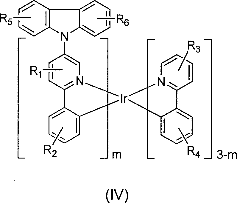
Heteroleptische Komplexe der Formel (V) werden auch bereit gestellt: 
Für jeden der oben genannten heteroleptischen Komplexe kann m jeden geeigneten Wert haben. In einigen Ausführungsformen ist m 1. In anderen Ausführungsformen ist m 2.For any of the above heteroleptic complexes, m may have any suitable value. In some embodiments, m is 1. In other embodiments, m is 2.
In einigen Ausführungsformen der oben genannten heteroleptischen Komplexe weisen R1, R2, R3, R4, R5 und R6 die Werte auf, wie sie für die Verbindungen der Formel (I) genannt werden. In einigen Ausführungsformen wird jedoch jedes der R1, R2, R3, R4, R5 und R6 unabhängig ausgewählt aus der Gruppe bestehend aus: Wasserstoff, Deuterium, Alkyl, Cycloalkyl, Aryl, Heteroaryl und Kombinationen davon. In einigen anderen Ausführungsformen wird jeder R1, R2, R3, R4, R5 und R6 unabhängig ausgewählt aus der Gruppe bestehend aus: Wasserstoff, Deuterium, Alkyl und Kombinationen davon. In einigen weiteren Ausführungsformen wird jeder der R1, R2, R3, R4, R5 und R6 unabhängig ausgewählt aus der Gruppe bestehend aus: Wasserstoff, Deuterium, Methyl, Ethyl, Propyl, 1-Methylethyl, Butyl, 1-Methylpropyl, 2-Methylpropyl, Pentyl, 1-Methylbutyl, 2-Methylbutyl, 3-Methylbutyl, 1,1-Dimethylpropyl, 1,2-Dimethylpropyl, 2,2-Dimethylpropyl, Cyclopentyl, Cyclohexyl, Phenyl, 2,6-Dimethylphenyl, 2,4,6-Trimethylphenyl, 2,6-Diisopropylphenyl und Kombinationen davon.In some embodiments of the above-mentioned heteroleptic complexes, R 1 , R 2 , R 3 , R 4 , R 5 and R 6 have the values given for the compounds of formula (I). However, in some embodiments, each of R 1 , R 2 , R 3 , R 4 , R 5, and R 6 is independently selected from the group consisting of hydrogen, deuterium, alkyl, cycloalkyl, aryl, heteroaryl, and combinations thereof. In some other embodiments, each of R 1 , R 2 , R 3 , R 4 , R 5, and R 6 is independently selected from the group consisting of hydrogen, deuterium, alkyl, and combinations thereof. In some further embodiments, each of R 1 , R 2 , R 3 , R 4 , R 5, and R 6 is independently selected from the group consisting of: hydrogen, deuterium, methyl, ethyl, propyl, 1-methylethyl, butyl, 1- Methylpropyl, 2-methylpropyl, pentyl, 1-methylbutyl, 2-methylbutyl, 3-methylbutyl, 1,1-dimethylpropyl, 1,2-dimethylpropyl, 2,2-dimethylpropyl, cyclopentyl, cyclohexyl, phenyl, 2,6-dimethylphenyl, 2,4,6-trimethylphenyl, 2,6-diisopropylphenyl and combinations thereof.
Heteroleptische Komplexe werden bereitgestellt, wobei die Komplexe ausgewählt werden aus der Gruppe bestehend aus: 

Heteroleptische Komplexe werden bereitgestellt, wobei die Komplexe ausgewählt werden aus der Gruppe bestehend aus: 
Heteroleptische Komplexe werden bereitgestellt, wobei die Komplexe ausgewählt werden aus der Gruppe bestehend aus: 
Heteroleptische Komplexe werden bereitgestellt, wobei die Komplexe ausgewählt werden aus der Gruppe bestehend aus: 
Eine Vorrichtung wird auch bereitgestellt. Die Vorrichtung kann eine Anode, eine Kathode und eine organische Schicht einschließen, die zwischen der Anode und der Kathode angeordnet ist, wobei die organische Schicht einen heteroleptischen Komplex nach einem der vorausgegangenen Ausführungsformen umfasst.A device is also provided. The device may include an anode, a cathode, and an organic layer disposed between the anode and the cathode, the organic layer comprising a heteroleptic complex according to any one of the preceding embodiments.
Die Erfindung ist nicht auf einen bestimmten Typ von Vorrichtung beschränkt. In einigen Ausführungsformen ist die Vorrichtung ein Verbraucherprodukt. In einigen Ausführungsformen ist die Vorrichtung eine organische Licht emittierende Vorrichtung (OLED). In anderen Ausführungsformen umfasst die Vorrichtung eine Leuchtplatte.The invention is not limited to any particular type of device. In some embodiments, the device is a consumer product. In some embodiments, the device is an organic light emitting device (OLED). In other embodiments, the device comprises a light panel.
In einigen Ausführungsformen ist die organische Schicht der Vorrichtung eine emissive Schicht. In einigen dieser Ausführungsformen ist der heteroleptische Komplex ein emissives Dotiermittel. In einigen anderen Ausführungsformen ist der heteroleptische Komplex ein nicht-emissives Dotiermittel.In some embodiments, the organic layer of the device is an emissive layer. In some of these embodiments, the heteroleptic complex is an emissive dopant. In some other embodiments, the heteroleptic complex is a non-emissive dopant.
In einigen Ausführungsformen umfasst die organische Schicht der Vorrichtung ferner einen Host.In some embodiments, the organic layer of the device further comprises a host.
In einigen dieser Ausführungsformen umfasst der Host ein Triphenylen, welches benzokondensiertes Thiophen oder benzokondensiertes Furan enthält, wobei jeder Substituent in dem Host einen nicht-kondensierten Substituenten enthält, unabhängig ausgewählt aus der Gruppe bestehend aus CnH2n+1, OCnH2n+1, OAr1, N(CnH2n+1)2, N(Ar1)(Ar2), CH=CH-CnH2n+1, C≡CHCnH2n+1, Ar1, Ar1-Ar2, CnH2n-Ar1, oder keine Substitution, wobei n von 1 bis 10 ist und wobei Ar1 und Ar2 unabhängig ausgewählt werden aus der Gruppe bestehend aus Benzol, Biphenyl, Naphtalen, Thiphenylen, Carbazol und heteroaromatischen Analoga davon. In einigen dieser Ausführungsformen ist der Host eine Verbindung ausgewählt aus der Gruppe bestehend aus: 
In einigen anderen Ausführungsformen umfasst der Host einen Metallkomplex. Kombination mit anderen MaterialienIn some other embodiments, the host comprises a metal complex. Combination with other materials
Die Materialien, die hierin als nützlich für eine bestimmte Schicht in einer organischen Licht emittierenden Vorrichtung beschrieben werden, können in Kombination mit einer großen Vielzahl von anderen Materialien, die in der Vorrichtung vorhanden sind, verwendet werden. Die hierin offenbarten Materialien können zum Beispiel in Verbindung mit einer großen Vielzahl von Hosts, Transportschichten, Sperrschichten, Injektionsschichten, Elektroden und anderen Schichten, die vorhanden sein können, verwendet werden. Die beschriebenen oder nachstehend genannten Materialien sind nicht beschränkende Beispiele von Materialien, die mit den in Kombination hierin offenbarten Verbindungen nützlich sein können und der Fachmann kann einfach die Literatur hinzu ziehen, um andere Materialien, die in Kombination nützlich sein können, zu identifizieren.The materials described herein as being useful for a particular layer in an organic light emitting device may be used in combination with a wide variety of other materials present in the device. For example, the materials disclosed herein may be used in conjunction with a wide variety of hosts, transport layers, barrier layers, injection layers, electrodes, and other layers that may be present. The materials described or below are non-limiting examples of materials that may be useful with the compounds disclosed in combination herein, and those skilled in the art can simply consult the literature to identify other materials that may be useful in combination.
Ein locheinspritzendes-/transportierendes Material, welches in der vorliegenden Erfindung verwendet wird, ist nicht besonders beschränkt und jede Verbindung kann verwendet werden, solange die Verbindung typischerweise als ein lochinjizierendes-/transportierendes Material verwendet wird. Beispiele dieses Materials schließen ein, sind aber nicht beschränkt auf: ein Phthalocyanin oder Porphryin Derivat; ein aromatisches Aminderivat; ein Indolcarbazolderivat; ein Polymer, welches Fluorkohlenwasserstoff enthält; ein Polymer mit Leitfähigkeitsdotiermitteln; ein leitfähiges Polymer, wie PEDOT/PSS; ein selbst-assemblierendes Monomer, abstammend aus Verbindungen wie Phosphonsäure und Silanderivaten; ein Metalloxidderivat wie MoOx; eine p-Typ halbleitende organische Verbindung wie 1,4,5,8,9,12-Hexaazatriphenylenhexacarbonitril; ein Metallkomplex und vernetzbare Verbindungen. A hole injecting / transporting material used in the present invention is not particularly limited, and any compound may be used as long as the compound is typically used as a hole injecting / transporting material. Examples of this material include, but are not limited to: a phthalocyanine or porphryin derivative; an aromatic amine derivative; an indolocarbazole derivative; a polymer containing fluorohydrocarbon; a polymer with conductivity dopants; a conductive polymer such as PEDOT / PSS; a self-assembling monomer derived from compounds such as phosphonic acid and silane derivatives; a metal oxide derivative such as MoO x ; a p-type semiconductive organic compound such as 1,4,5,8,9,12-hexaazatriphenylenehexacarbonitrile; a metal complex and crosslinkable compounds.
Beispiele für aromatische Aminderivate, die in HIL oder HTL verwendet werden, schließen ein, sind aber nicht beschränkt auf die folgenden allgemeinen Strukturen: 
Jedes von Ar1 bis Ar9 wird ausgewählt aus der Gruppe bestehend aus aromatischen, cyclischen Kohlenwasserstoffverbindungen, wie Benzol, Biphenyl, Triphenyl, Triphenylen, Naphtalen, Anthracen, Phenalen, Phenanthren, Fluoren, Pyren, Chrysen, Perylen, Azulen; der Gruppe bestehend aus aromatischen heterocyclischen Verbindungen wie Dibenzothiopen, Dibenzofuran, Dibenzoselenophen, Furan, Thiophen, Benzofuran, Benzothiophen, Benzoselenophen, Carbazol, Indolocarbazol, Pyridylindol, Pyrrolodipyridin, Pyrazol, Imidazol, Triazol, Oxazol, Thiazol, Oxadiazol, Oxatriazol, Dioxazol, Thiadiazol, Pyridin, Pyridazin, Pyrimidin, Pyrazin, Triazin, Oxazin, Oxathiazin, Oxadiazin, Indol, Benzimidazol, Indazol, Indoxazin, Benzoxazol, Benzisoxazol, Benzothiazol, Chinolin, Isochinolin, Cinnolin, Chinazolin, Chinoxalin, Naphthyridin, Phthalazin, Pteridin, Xanthen, Acridin, Phenazin, Phenothiazin, Phenoxazin, Benzofuropyridin, Furodipyridin, Benzothienopyridin, Thienodipyridin, Benzoselenophenopyridin, und Selenphenodipyridin; und der Gruppe bestehend aus 2 bis 10 cyclischen Struktureneinheiten, welche Gruppen desselben Typs oder verschiedener Typen sind, ausgewählt aus der aromatischen cyclischen Kohlenwasserstoffgruppe und der aromatischen heterocyclischen Gruppe und sind aneinander direkt oder durch wenigstens ein Sauerstoffatom, Stickstoffatom, Schwefelatom, Siliziumatom, Phosphoratom, Boratom, eine Kettenstruktureinheit und der aliphatischen cyclischen Gruppe miteinander gebunden. Wobei jedes Ar weiter durch einen Substituenten substituiert ist, ausgewählt aus der Gruppe bestehend aus Wasserstoff, Deuterium, Halogen, Alkyl, Cykloalkyl, Heteroalkyl, Arylalkyl, Alkoxy, Aryloxy, Amino, Silyl, Alkenyl, Cykloalkenyl, Heteroalkenyl, Alkinyl, Aryl, Hereoaryl, Azyl, Karbonyl, Karbonsäuren, Ester, Nitril, Isonitril, Sulfanyl, Sulfinyl, Sulfonyl, Phosphino, und Kombinationen davon.Each of Ar 1 to Ar 9 is selected from the group consisting of aromatic cyclic hydrocarbon compounds such as benzene, biphenyl, triphenyl, triphenylene, naphthalene, anthracene, phenalen, phenanthrene, fluorene, pyrene, chrysene, perylene, azulene; the group consisting of aromatic heterocyclic compounds such as dibenzothiophene, dibenzofuran, dibenzoselenophene, furan, thiophene, benzofuran, benzothiophene, benzoselenophene, carbazole, indolocarbazole, pyridylindole, pyrrolodipyridine, pyrazole, imidazole, triazole, oxazole, thiazole, oxadiazole, oxatriazole, dioxazole, thiadiazole, Pyridine, pyridazine, pyrimidine, pyrazine, triazine, oxazine, oxathiazine, oxadiazine, indole, benzimidazole, indazole, indoxazine, benzoxazole, benzisoxazole, benzothiazole, quinoline, isoquinoline, cinnoline, quinazoline, quinoxaline, naphthyridine, phthalazine, pteridine, xanthene, acridine, Phenazine, phenothiazine, phenoxazine, benzofuropyridine, furodipyridine, benzothienopyridine, thienodipyridine, benzoselenophenopyridine, and selenophenodipyridine; and the group consisting of 2 to 10 cyclic structural units which are groups of the same type or different types selected from the aromatic cyclic hydrocarbon group and the aromatic heterocyclic group and are adjacent to each other or at least one oxygen atom, nitrogen atom, sulfur atom, silicon atom, phosphorus atom, boron atom , a chain structural unit and the aliphatic cyclic group bonded together. Wherein each Ar is further substituted by a substituent selected from the group consisting of hydrogen, deuterium, halogen, alkyl, cycloalkyl, heteroalkyl, arylalkyl, alkoxy, aryloxy, amino, silyl, alkenyl, cycloalkenyl, heteroalkenyl, alkynyl, aryl, hereoaryl, Acyl, carbonyl, carboxylic acids, esters, nitrile, isonitrile, sulfanyl, sulfinyl, sulfonyl, phosphino, and combinations thereof.
In einem Aspekt werden Ar1 bis Ar9 unabhängig ausgewählt aus der Gruppe bestehend aus: 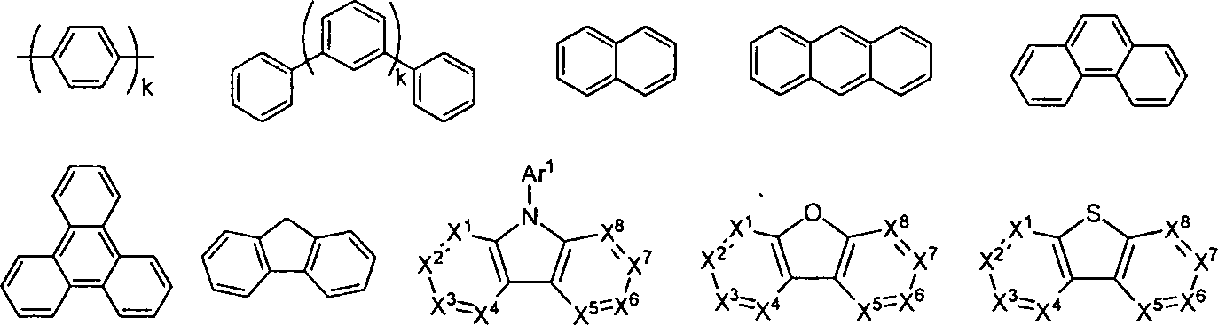
k ist eine ganze Zahl von 1 bis 20; X1 bis X8 ist C (einschließlich CH) oder N; Ar1 hat dieselbe Gruppe wie oben definiert. k is an integer from 1 to 20; X 1 to X 8 is C (including CH) or N; Ar 1 has the same group as defined above.
Beispiele von Metallkomplexen, die in HIL oder HTL verwendet werden, schließen ein, sind aber nicht beschränkt auf folgende allgemeine Formel: 
M ist ein Metall, dass ein Atomgewicht größer als 40 aufweist; (Y1-Y2) ist ein zweizähniger Ligand, Y1 und Y2 werden unabhängig ausgewählt aus C, N, O, P, und S; L ist ein Hilfsligand; m ist ein ganzzahliger Wert von 1 bis zur maximalen Anzahl von Liganden, die an das Metall gebunden sein können; und m + n ist die maximale Anzahl von Liganden, die an das Metall gebunden sein können.M is a metal having an atomic weight greater than 40; (Y 1 -Y 2 ) is a bidentate ligand, Y 1 and Y 2 are independently selected from C, N, O, P, and S; L is an auxiliary ligand; m is an integer value of 1 to the maximum number of ligands that can be attached to the metal; and m + n is the maximum number of ligands that can be attached to the metal.
In einem Aspekt ist (Y1-Y2) ein 2-Phenylpyridinderivat.In one aspect, (Y 1 -Y 2 ) is a 2-phenylpyridine derivative.
In einem anderem Aspekt ist (Y1-Y2) ein Carbenligand.In another aspect, (Y 1 -Y 2 ) is a carbene ligand.
In einem anderem Aspekt ist M ausgewählt aus Ir, Pt, Os und Zn.In another aspect, M is selected from Ir, Pt, Os and Zn.
In einem weiteren Aspekt weist der Metallkomplex das kleinste Oxidationspotential in Lösung gegen ein Fc+/Fc Paar weniger als ungefähr 0,6 V auf.In another aspect, the metal complex has the lowest oxidation potential in solution against an Fc + / Fc pair less than about 0.6V.
Zusätzlich zu den wie oben beschriebenen Hostmaterialien kann die Vorrichtung ferner andere Hostmaterialien umfassen. Beispiele solch anderer Hostmaterialien sind nicht besonders beschränkt und alle Metallkomplexe oder organische Verbindungen können verwendet werden, solange die Tripletenergie des Host größer ist als die des Dotiermittels. Während die untere Tabelle die Hostmaterialien kategorisiert, die für die Vorrichtungen, welche verschiedene Farben emittieren, bevorzugt sind, kann jedes Hostmaterial mit jedem Dotiermittel verwendet werden, solange die Tripletkriterien erfüllt sind.In addition to the host materials as described above, the device may further include other host materials. Examples of such other host materials are not particularly limited, and any metal complexes or organic compounds may be used as long as the triplet energy of the host is larger than that of the dopant. While the lower table categorizes the host materials that are preferred for the devices that emit different colors, any host material can be used with any dopant as long as the triplet criteria are met.
Beispiele von Metallkomplexen, die als Host verwendet werden, werden mit der folgenden allgemeinen Formel bevorzugt: 
M ist ein Metall; (Y3-Y4) ist ein zweizähniger Ligand, Y3 und Y4 werden unabhängig ausgewählt aus C, N, O, P, und S; L ist ein Hilfsligand; m ist ein ganzzahliger Wert von 1 bis zur maximalen Anzahl von Liganden, die an das Metall gebunden sein können; und m + n ist die maximale Anzahl von Liganden, die an das Metall gebunden sein können.M is a metal; (Y 3 -Y 4 ) is a bidentate ligand, Y 3 and Y 4 are independently selected from C, N, O, P, and S; L is an auxiliary ligand; m is an integer value of 1 to the maximum number of ligands that can be attached to the metal; and m + n is the maximum number of ligands that can be attached to the metal.
In einem Aspekt sind die Metallkomplexe: 
(O-N) ist ein zweizähniger Ligand, der ein an O- und N-Atome koordiniertes Metall aufweist.(O-N) is a bidentate ligand containing a metal coordinated to O and N atoms.
In einem anderen Aspekt ist M ausgewählt aus Ir und Pt.In another aspect, M is selected from Ir and Pt.
In einem anderen Aspekt ist (Y3-Y4) ein Carben Ligand.In another aspect, (Y 3 -Y 4 ) is a carbene ligand.
Beispiele für organische Verbindungen, die als Host verwendet werden, werden ausgewählt aus der Gruppe bestehend aus aromatischen cyclischen Kohlenwasserstoffverbindungen, wie Benzol, Biphenyl, Triphenyl, Triphenylen, Naphtalin, Anthracen, Phenalen, Phenanthren, Fluoren, Pyren, Chrysen, Perylen, Azulen; der Gruppe bestehend aus aromatischen heterocyclischen Verbindungen wie Dibenzothiopen, Dibenzofuran, Dibenzoselenophen, Furan, Thiophen, Benzofuran, Benzothiophen, Benzoselenophen, Carbazol, Indolocarbazol, Pyridylindol, Pyrrolodipyridin, Pyrazol, Imidazol, Triazol, Oxazol, Thiazol, Oxadiazol, Oxatriazol, Dioxazol, Thiadiazol, Pyridin, Pyridazin, Pyrimidin, Pyrazin, Triazin, Oxazin, Oxathiazin, Oxadiazin, Indol, Benzimidazol, Indazol, Indoxazin, Benzoxazol, Benzisoxazol, Benzthiazol, Chinolin, Isochinolin, Cinnolin, Chinoxalin, Naphthyridin, Phthalazin, Pteridin, Xanthen, Acridin, Phenazin, Phenothiazin, Phenoxazin, Benzothiazol, Wuinolin, Isochinolin, Cinnolin, Chinazolin, Chinoxalin, Naphthyridin, Phthalazin, Pteridin, Xanthen, Acridin, Phenazin, Phenothiazin, Phenoxazin, Benzofuropyridin, Furodipyridin, Benzothienopyridin, Thienodipyridin, Benzoselenophenopyridin, und Selenphenodipyridin; und der Gruppe bestehend aus 2 bis 10 cyclischen Struktureneinheiten, welche Gruppen des selben Typs oder verschiedener Typen sind, ausgewählt aus der aromatischen cyclischen Kohlenwasserstoffgruppe und der aromatischen heterocyclischen Gruppe und direkt aneinander gebunden oder durch wenigstens ein Sauerstoffatom, Stickstoffatom, Schwefelatom, Siliziumatom, Phosphoratom, Boratom, Kettenstruktureinheit und der aliphatischen cyclischen Gruppe. Wobei jede Gruppe weiter durch einen Substituenten substituiert ist, ausgewählt aus der Gruppe bestehend aus Wasserstoff, Deuterium, Halogen, Alkyl, Cycloalkyl, Heteroalkyl, Arylalkyl, Alkoxy, Aryloxy, Amino, Silyl, Alkenyl, Cycloalkenyl, Heteroalkenyl, Alkinyl, Aryl, Hereoaryl, Azyl, Carbonyl, Carbonsäuren, Ester, Nitril, Isonitril, Sulfanyl, Sulfinyl, Sulfonyl, Phosphino und Kombinationen davon.Examples of organic compounds used as hosts are selected from the group consisting of aromatic cyclic hydrocarbon compounds, such as benzene, biphenyl, Triphenyl, triphenylene, naphthalene, anthracene, phenalen, phenanthrene, fluorene, pyrene, chrysene, perylene, azulene; the group consisting of aromatic heterocyclic compounds such as dibenzothiophene, dibenzofuran, dibenzoselenophene, furan, thiophene, benzofuran, benzothiophene, benzoselenophene, carbazole, indolocarbazole, pyridylindole, pyrrolodipyridine, pyrazole, imidazole, triazole, oxazole, thiazole, oxadiazole, oxatriazole, dioxazole, thiadiazole, Pyridine, pyridazine, pyrimidine, pyrazine, triazine, oxazine, oxathiazine, oxadiazine, indole, benzimidazole, indazole, indoxazine, benzoxazole, benzisoxazole, benzthiazole, quinoline, isoquinoline, cinnoline, quinoxaline, naphthyridine, phthalazine, pteridine, xanthene, acridine, phenazine, Phenothiazine, phenoxazine, benzothiazole, wuinoline, isoquinoline, cinnoline, quinazoline, quinoxaline, naphthyridine, phthalazine, pteridine, xanthene, acridine, phenazine, phenothiazine, phenoxazine, benzofuropyridine, furodipyridine, benzothienopyridine, thienodipyridine, benzoselenophenopyridine, and selenophenodipyridine; and the group consisting of 2 to 10 cyclic structural units which are groups of the same type or different types selected from the aromatic cyclic hydrocarbon group and the aromatic heterocyclic group and bonded to each other directly or through at least one oxygen atom, nitrogen atom, sulfur atom, silicon atom, phosphorus atom, Boron atom, chain structural unit and the aliphatic cyclic group. Wherein each group is further substituted by a substituent selected from the group consisting of hydrogen, deuterium, halogen, alkyl, cycloalkyl, heteroalkyl, arylalkyl, alkoxy, aryloxy, amino, silyl, alkenyl, cycloalkenyl, heteroalkenyl, alkynyl, aryl, hereoaryl, Acyl, carbonyl, carboxylic acids, esters, nitrile, isonitrile, sulfanyl, sulfinyl, sulfonyl, phosphino, and combinations thereof.
In einem Aspekt enthält die Hostverbindung wenigstens eine der folgenden Gruppen in dem Molekül: 
R1 bis R7 werden unabhängig ausgewählt aus der Gruppe bestehend aus Wasserstoff, Deuterium, Halogen, Alkyl, Cykloalkyl, Heteroalkyl, Aryl, Alkyl, Alkoxy, Aryloxy, Amino, Silyl, Alkenyl, Cycloalkenyl, Heteroalkenyl, Alkinyl, Aryl, Heteroaryl, Acyl, Carbonyl, Carbonsäuren, Ester, Nitril, Isonitril, Sulfanyl, Sulfinyl, Sulfonyl, Phosphino und Kombinationen davon, wenn sie ein Aryl oder Heteroaryl sind, haben sie ähnliche Definition wie die oben erwähnten Ar's; k ist eine ganze Zahl von 0 bis 20; X1 bis X8 werden ausgewählt aus C (einschließlich CH) oder N; und Z1 und Z2 werden aus NR1, O oder S ausgewählt.R 1 to R 7 are independently selected from the group consisting of hydrogen, deuterium, halogen, alkyl, cycloalkyl, heteroalkyl, aryl, alkyl, alkoxy, aryloxy, amino, silyl, alkenyl, cycloalkenyl, heteroalkenyl, alkynyl, aryl, heteroaryl, acyl , Carbonyl, carboxylic acids, esters, nitrile, isonitrile, sulfanyl, sulfinyl, sulfonyl, phosphino, and combinations thereof, when they are an aryl or heteroaryl, have similar definition to the above-mentioned Ar's; k is an integer from 0 to 20; X 1 to X 8 are selected from C (including CH) or N; and Z 1 and Z 2 are selected from NR 1 , O or S.
Eine Lochsperrschicht (HBL) kann verwendet werden, um die Anzahl der Löcher und/oder Excitons, die die emissive Schicht verlassen, zu reduzieren. Die Anwesenheit einer solchen Sperrschicht in einer Vorrichtung kann in substantiell höheren Effizienzen münden, verglichen zu einer ähnlichen Vorrichtung, der eine Sperrschicht fehlt. Eine Sperrschicht kann auch verwendet werden, um Emissionen in einem gewünschten Bereich eines OLEDs zu beschränken.A hole blocking layer (HBL) can be used to reduce the number of holes and / or excitons leaving the emissive layer. The presence of such a barrier layer in a device can result in substantially higher efficiencies compared to a similar device that lacks a barrier layer. A barrier may also be used to limit emissions in a desired range of an OLED.
In einem Aspekt enthält die in HBL verwendete Verbindung dasselbe Molekül oder dieselben funktionellen Gruppen, die als Host, wie oben beschrieben, verwendet werden.In one aspect, the compound used in HBL contains the same molecule or functional groups used as a host as described above.
In einem anderen Aspekt enthält die in HBL verwendete Verbindung wenigstens eine der folgenden Gruppen in dem Molekül: 
k ist eine ganze Zahl von 0 bis 20; L ist ein Hilfsligand, m ist eine ganze Zahl von 1 bis 3.k is an integer from 0 to 20; L is an auxiliary ligand, m is an integer from 1 to 3.
Die Elektronentransportschicht (ETL) kann ein Material einschließen, welches Elektronen transportieren kann. Die Elektronentransportschicht kann intrinsisch (undotiert) oder dotiert sein. Das Dotieren kann verwendet werden, um die Leitfähigkeit zu verstärken. Beispiele des ETL-Materials sind nicht besonders beschränkt und alle Metallkomplexe oder organische Verbindungen können verwendet werden, solange sie typischerweise verwendet werden, um Elektronen zu transportieren.The electron transport layer (ETL) may include a material that can transport electrons. The electron transport layer may be intrinsic (undoped) or doped. The doping can be used to increase the conductivity. Examples of the ETL material are not particularly limited, and any metal complexes or organic compounds can be used as long as they are typically used to transport electrons.
In einem Aspekt enthält die in ETL verwendete Verbindung wenigstens eine der folgenden Gruppen im Molekül: 
R1 wird ausgewählt aus der Gruppe bestehend aus: Wasserstoff, Deuterium, Halogen, Alkyl, Cykloalkyl, Heteroalkyl, Aryl, Alkyl, Alkoxy, Aryloxy, Amino, Silyl, Alkenyl, Cykloalkenyl, Heteroalkenyl, Alkinyl, Aryl, Heteroaryl, Acyl, Carbonyl, Carbonsäuren, Ester, Nitril, Isonitril, Sulfanyl, Sulfinyl, Sulfonyl, Phosphino und Kombinationen davon, wenn sie ein Aryl oder Heteroaryl ist, hat sie die ähnliche Definition wie die oben erwähnten Ar's; Ar1 bis Ar8 haben die ähnlichen Definitionen wie die oben genannten Ar's; k ist eine ganze Zahl von 0 bis 20; X1 bis X8 werden ausgewählt aus C (einschließlich CH) oder N.R 1 is selected from the group consisting of: hydrogen, deuterium, halogen, alkyl, cycloalkyl, heteroalkyl, aryl, alkyl, alkoxy, aryloxy, amino, silyl, alkenyl, cycloalkenyl, heteroalkenyl, alkynyl, aryl, heteroaryl, acyl, carbonyl, Carboxylic acids, esters, nitrile, isonitrile, sulfanyl, sulfinyl, sulfonyl, phosphino and combinations thereof, when it is an aryl or heteroaryl, has the similar definition as the above-mentioned Ar's; Ar 1 to Ar 8 have the similar definitions as the above-mentioned Ar's; k is an integer from 0 to 20; X 1 to X 8 are selected from C (including CH) or N.
In einem anderen Aspekt enthalten die in ETL verwendeten Metallkomplexe, welche aber nicht auf die folgende allgemeine Formel beschränkt sind: 
(O-N) oder (N-N) ist ein zweizähniger Ligand, der Metall aufweist, welches an die O-, N- oder N-, N-Atome koordiniert ist; L ist ein Hilfsligand; M ist ein ganzzahliger Wert von 1 bis zur maximalen Anzahl von Liganden, die an das Metall gebunden sein können.(O-N) or (N-N) is a bidentate ligand having metal coordinated to the O, N or N, N atoms; L is an auxiliary ligand; M is an integer value of 1 to the maximum number of ligands that can be attached to the metal.
In allen der oben erwähnten Verbindungen, die in jeder Schicht der OLED-Vorrichtung verwendet werden, können die Wasserstoffatome teilweise oder vollständig deuteriert sein. Daher umfasst unbeschränkt jeder spezifisch aufgelistete Substituent wie Methyl, Phenyl, Pyridyl, etc. undeuterierte, teilweise deuterierte und vollständig deuterierte Versionen davon. Ähnlich umfassen unbeschränkt Klassen von Substituenten wie Alkyl, Aryl, Cykloalkyl, Heteroaryl, etc. undeuterierte, teilweise deuterierte und vollständig deuterierte Versionen davon.In all of the above-mentioned compounds used in each layer of the OLED device, the hydrogen atoms may be partially or completely deuterated. Thus, any specifically listed substituent, such as methyl, phenyl, pyridyl, etc., includes indefinitely, partially deuterated and fully deuterated versions thereof. Similarly, unrestricted classes of substituents such as alkyl, aryl, cycloalkyl, heteroaryl, etc. include undeuterated, partially deuterated and fully deuterated versions thereof.
Zusätzlich zu und/oder in Kombination mit den Materialien, die hierin offenbart sind, können viele Lochinjektionsmaterialien, Lochtransportmaterialien, Hostmaterialien, Dotiermittelmaterialien, Exciton-Lochsperrschichtmaterialien, Elektronentransport und Elektroneninjektionsmaterialien in einer OLED verwendet werden. Nicht beschränkende Beispiele der Materialien, die in einer OLED in Kombination mit Materialien, welche hierin offenbart sind, können wie in Tabelle 1 unten aufgelistet, verwendet werden. Tabelle 1 listet nicht-beschränkende Klassen von Materialien, nicht-beschränkende Beispiele von Verbindungen für jede Klasse und Referenzen auf, die die Materialien offenbaren.In addition to and / or in combination with the materials disclosed herein, many hole injection materials, hole transport materials, host materials, dopant materials, exciton hole barrier materials, electron transport, and electron injection materials can be used in an OLED. Non-limiting examples of materials used in an OLED in combination with materials disclosed herein may be used as listed in Table 1 below. Table 1 lists non-limiting classes of materials, non-limiting examples of compounds for each class, and references that disclose the materials.
TABELLE 1 


EXPERIMENTELLESEXPERIMENTAL
Verbindungsbeispieleconnection Examples
Einige der heteroleptischen Komplexe wurden wie folgt synthetisiert:Some of the heteroleptic complexes were synthesized as follows:
Synthese von Verbindung 1.Synthesis of Compound 1.
Herstellung von 5-Brom-2-Phenyl-Pyridin. 
5-Brom-2-Iodpyridin (15 g, 52,8 mmol), Phenylboronsäure (6,44 g, 52,8 mmol), Tetrakis(Triphenylphosphin)palladium(0) (0,611 g, 0,528 mmol) und Kaliumcarbonat (83 g, 598 mmol) wurden zu 260 ml 4:1 DME und Wasser hinzugegeben. Das Reaktionsgemisch wurde mit Stickstoffgas für 30 min. entgast und unter Rückfluss für 18 Stunden in einer inerten Umgebung gerührt. Das abgekühlte Reaktionsgemisch wurde auf Wasser gegossen und zwischen Kochsalzlösung und Ethylacetat verteilt. Organische Schichten wurden vereint und über MgSO4 getrocknet und Lösungsmittel wurden unter reduziertem Druck entfernt. Das Rohprodukt wurde durch Säulenchromatographie über Silica Gel unter Verwendung von 5–15% DCM/Hexane als Elutionsmittel gereinigt. 4,18 g (33,8%) von 5-Brom-2-Phenylpyridin wurden als weißer Feststoff isoliert.5-Bromo-2-iodopyridine (15 g, 52.8 mmol), phenyl boronic acid (6.44 g, 52.8 mmol), tetrakis (triphenylphosphine) palladium (0) (0.611 g, 0.528 mmol) and potassium carbonate (83 g , 598 mmol) were added to 260 ml of 4: 1 DME and water. The reaction mixture was treated with nitrogen gas for 30 min. degassed and stirred under reflux for 18 hours in an inert environment. The cooled reaction mixture was poured onto water and partitioned between brine and ethyl acetate. Organic layers were combined and dried over MgSO 4 and solvents were removed under reduced pressure. The crude product was purified by column chromatography over silica gel using 5-15% DCM / hexanes as eluent. 4.18 g (33.8%) of 5-bromo-2-phenylpyridine were isolated as a white solid.
Herstellung von N,N,6-Triphenylpyridin-3-Amin 
5-Brom-2-Phenylpyridin (7,0 g, 29,9 mmol) und Diphenylamin (6,07 g, 35,9 mmol) wurden in 300 ml m-Xylol in einem 500 ml 3-Hals-Rundkolben gelöst, dann wurde Stickstoff direkt in die klare Lösung für 30 Minuten geblasen. Natrium-t-Gutoxid (5,75 g, 59,8 mmol), Binap (1,49 g, 2,39 mmol) und Pd2-dba3 (1,10 g, 1,20 mmol) wurden zur Lösung in dieser Reihenflge hinzugefügt. Die Reaktion wurde unter kräftigem Rückfluss in Stickstoff-Atmosphäre über Nacht erhitzt. Das dunkelbraune Reaktionsgemisch wurde dann in einen Schreidetrichter mit Ethylacetat und Wasser überführt. Der wässrige Teil wurde zweimal mit Ethylacetat extrahiert. Die vereinigten organischen Schichten wurden mit Natriumsulfat getrocknet, filtriert und zu einem braunen Feststoff rotationsverdampft. Das Rohprodukt wurde auf Celite absorbiert und mit Kieselgel Säulenchromatographie unter Verwendung eines 25/75 DCM/Hexan 100% DCM Lösungsmittelsystem-Gradienten aufgereinigt. Der Hauptproduktspot wurde gewonnen und zu einem beigen Feststoff eingedampft (8,0 g).5-Bromo-2-phenylpyridine (7.0 g, 29.9 mmol) and diphenylamine (6.07 g, 35.9 mmol) were dissolved in 300 mL of m-xylene in a 500 mL 3-neck round bottom flask, then Nitrogen was bubbled directly into the clear solution for 30 minutes. Sodium t-good oxide (5.75 g, 59.8 mmol), Binap (1.49 g, 2.39 mmol) and Pd 2 -dba 3 (1.10 g, 1.20 mmol) were added to the solution in added to this series flights. The reaction was heated at high reflux in a nitrogen atmosphere overnight. The dark brown reaction mixture was then transferred to a separatory funnel with ethyl acetate and water. The aqueous portion was extracted twice with ethyl acetate. The combined organic layers were dried with sodium sulfate, filtered and rotary evaporated to a brown solid. The crude product was absorbed on celite and purified by silica gel column chromatography using a 25/75 DCM /
Herstellung von Verbindung 1. 
N,N,6-Triphenylpyridin-3-Amin (6,37 g, 19,75 mmol), Phenylpyridin Iridium Triflat-Zwischenprodukt (4,7 g, 6,58 mmol) und 130 ml Ethanol wurden in einem 250 ml Rundkolben kombiniert. Ein Rückflusskühler wurde angelegt, das System wurde dann evakuiert und dreimal mit Stickstoff gespült. Die Suspension wurde bis zu einem heftigen Rückfluss in einem Ölbad über Nacht erhitzt. Die Reaktion wurde auf Raumtemperatur abgekühlt, hinzugefügte Celite wurde dann aus einer hellgelben Suspension durch Verwendung eines Celitekissen in einem gesinterten Filtertrichter abfiltriert. Der Feststoff wurde gut mit Ethanol gewaschen. Das Rohprodukt wurde durch Waschen der Celite mit DCM gewonnen, dann wurde das Filtrat zu einem gelben Feststoff verdampft. Die Probe wurde durch Verwenden von Kieselgel Säulenchromatographie mit einem 50/50 DCM/Hexan Lösungsmittelsystem aufgereinigt. Die gewünschten Fraktionen wurden vereint und zu einem orangegelben Feststoff rotationsverdampft (4,1 g). N, N, 6-triphenylpyridine-3-amine (6.37 g, 19.75 mmol), phenylpyridine, iridium triflate intermediate (4.7 g, 6.58 mmol) and 130 mL of ethanol were combined in a 250 mL round bottom flask , A reflux condenser was attached, the system was then evacuated and purged with nitrogen three times. The suspension was heated to a heavy reflux in an oil bath overnight. The reaction was cooled to room temperature, and added celite was then filtered from a light yellow suspension by using a celite pad in a sintered filter funnel. The solid was washed well with ethanol. The crude product was recovered by washing the celite with DCM, then the filtrate was evaporated to a yellow solid. The sample was purified by using silica gel column chromatography with a 50/50 DCM / hexane solvent system. The desired fractions were combined and rotary evaporated to an orange-yellow solid (4.1 g).
Die Probe wurde in 150 ml Toluol in einem 250 ml Rundkolben unter Stickstoff in einem Ölbad für 4 Stunden unter Rückfluss erhitzt. Die Suspension wurde entfernt und auf Raumtemperatur für eine Stunde heruntergekühlt, dann durch Filterpapier in einem Büchnertrichter filtriert. Der Feststoff wurde in einem Vakuumofen über Nacht weiter getrocknet, der auf 60°C eingestellt war, um die Verbindung 1 (2,70 g, 42,5% Ausbeute) zu ergeben.The sample was refluxed in 150 ml of toluene in a 250 ml round bottom flask under nitrogen in an oil bath for 4 hours. The suspension was removed and cooled down to room temperature for one hour, then filtered through filter paper in a Buchner funnel. The solid was further dried in a vacuum oven overnight, which was adjusted to 60 ° C to give Compound 1 (2.70 g, 42.5% yield).
Synthese von Verbindung D.Synthesis of Compound D.
Herstellung von Iridium Dimer: 
N,N,6-Triphenylpyridin-3-amin (2,27 g, 7,03 mmol) und Iridium(III)chlorid (1 g, 3,35 mmol) wurden in 40 ml eines 3:1 Gemischs aus Ethoxyethanol und Wasser gemischt. Das Reaktionsgemisch wurde durch Stickstoffgas entgast und unter Stickstoff für 18 Stunden unter Rückfluss gerührt. Das Reaktionsgemisch wurde auf Raumtemperatur abgekühlt und mit 50 ml Methanol verdünnt. Die festen Präzipitate wurden gesammelt und ohne weitere Aufreinigung verwendet.N, N, 6-Triphenylpyridin-3-amine (2.27 g, 7.03 mmol) and iridium (III) chloride (1 g, 3.35 mmol) were dissolved in 40 ml of a 3: 1 mixture of ethoxyethanol and water mixed. The reaction mixture was degassed by nitrogen gas and stirred under nitrogen for 18 hours under reflux. The reaction mixture was cooled to room temperature and diluted with 50 ml of methanol. The solid precipitates were collected and used without further purification.
Herstellung vom Iridium Triflat Zwischenprodukt. 
Silbertriflat (0,597 g, 2,325 mmol) wurde in 8 ml Methanol gelöst und Iridium Dimer (1,84 g, 1,057 mmol) wurde hinzugegeben, gefolgt von 15 ml Dichlormethan. Die Reaktionsmischung wurde unter Stickstoff im Dunklen für 18 Stunden unter Rückfluss erhitzt. Das abgekühlte Reaktionsgemisch wurde durch einen Celite plug filtriert. Lösungsmittel wurden aus dem Filtrat entfernt und der isolierte Feststoff wurde für den nächsten Schritt ohne weitere Aufreinigung verwendet. Silver triflate (0.597 g, 2.325 mmol) was dissolved in 8 mL of methanol and iridium dimer (1.84 g, 1.057 mmol) was added followed by 15 mL of dichloromethane. The reaction mixture was refluxed under nitrogen in the dark for 18 hours. The cooled reaction mixture was filtered through a Celite plug. Solvents were removed from the filtrate and the isolated solid was used for the next step without further purification.
Herstellung von Verbindung D. 
N,N,6-Triphenylpyridin-3-amin (1,846 g, 5,72 mmol) und Iridium Triflat Zwischenprodukt (2 g, 1,908 mmol) wurden zu 60 ml Ethanol hinzugegeben und unter Rückfluss für 18 Stunden gerührt. Das abgekühlte Gemisch wurde dann durch Celite filtriert und der Kuchen mit Ethanol gewaschen. Der Filtertrichter wurde dann auf einen getrennten Trichter gesetzt und das Produkt wurde mit Dichlormethan extrahiert. Das Eindampfen des Filtrats ergab 2,0 g eines rohen Feststoffs, der über Kieselgel durch Verwenden von 1:1 bis 7:3 Dichlormethan/Hexane als Elutionsmittel aufgereinigt wurde, um 1,45 g (66%) der Verbindung D zu erhalten.N, N, 6-Triphenylpyridin-3-amine (1.846 g, 5.72 mmol) and iridium triflate intermediate (2 g, 1.908 mmol) were added to 60 mL of ethanol and stirred at reflux for 18 h. The cooled mixture was then filtered through celite and the cake washed with ethanol. The filter funnel was then placed on a separate funnel and the product was extracted with dichloromethane. Evaporation of the filtrate gave 2.0 g of a crude solid which was purified on silica gel using 1: 1 to 7: 3 dichloromethane / hexanes as eluent to give 1.45 g (66%) of compound D.
Synthese von Verbindung 2.Synthesis of Compound 2.
Herstellung von 5-Brom-4-Methyl-2-Phenyl-Pyridin. 
2,5-Dibrom-4-Methylpyridin (25 g, 100 mmol) und Phenylboronsäure (12,15 g, 100 mmol) wurden in einen 1 L Kolben gegeben. DME (250 ml), Wasser (100 ml) und Kaliumcarbonat (27,5 g, 200 mmol) wurden dann hinzugegeben. Dies wurde vor der Zugabe von Tetrakis(triphenylphosphin)palladium(0) (5,76 g, 5%) entgast. Die Reaktion wurde über Nacht unter Rückfluss gerührt.2,5-Dibromo-4-methylpyridine (25 g, 100 mmol) and phenyl boronic acid (12.15 g, 100 mmol) were added to a 1 L flask. DME (250 ml), water (100 ml) and potassium carbonate (27.5 g, 200 mmol) were then added. This was degassed before the addition of tetrakis (triphenylphosphine) palladium (0) (5.76 g, 5%). The reaction was stirred at reflux overnight.
Das Gemisch wurde durch Celite filtriert und der Kuchen wurde mit Ethylacetat gewaschen. Das Filtrat wurde dann mit mehr Ethylacetat und Salzlösung verdünnt. Die Schichten wurden getrennt. Die organische Schicht wurde konzentriert und die chromatographierte (Kieselgel) Elution mit 0–15% DCM in Hexan, gefolgt von 10% Ethylacetat in Hexan, ergaben 18,9 g (77%) des Produkts als ein Öl.The mixture was filtered through celite and the cake was washed with ethyl acetate. The filtrate was then diluted with more ethyl acetate and brine. The layers were separated. The organic layer was concentrated and chromatographed (silica gel) elution with 0-15% DCM in hexane followed by 10% ethyl acetate in hexane gave 18.9 g (77%) of the product as an oil.
Herstellung von 4-Methyl-N-N,6-Triphenylpyridin-3-amin. 
5-Brom-4-Methyl-2-Phenylpyridin (7,44 g, 30,0 mmol) wurde in einen 500 ml 3-Hals-Kolben gegeben. Das Reaktionsgemisch wurde mit Xylol (250 ml) verdünnt. Diphenylamin (6,09 g, 36,0 mmol) wurde hinzugegeben und das Gemisch entgast. Natrium t-butoxid (5,77 g, 60,0 mmol) und 2,2'-bis(diphenylphosphino)-1,1'-binaphtalen (binap) (1,494 g, 2,400 mmol) und Pd2-dba3 (1,099 g, 1,200 mmol) wurden hinzugefügt. Dies wurde unter Rückfluss für 18 Stunden gerührt. Das rohe Gemisch wurde durch Celite filtriert und durch Verwenden einer mobilen Phase von zunächst 1:1 DCM-Hexan, dann 5–10% Ethylacetat in Hexan chromatographiert, um 7,68 g (76%) eines Produkts als einen hellgelben Schaum zu ergeben.5-Bromo-4-methyl-2-phenylpyridine (7.44 g, 30.0 mmol) was added to a 500 mL 3-necked flask. The reaction mixture was diluted with xylene (250 ml). Diphenylamine (6.09 g, 36.0 mmol) was added and the mixture degassed. Sodium t -butoxide (5.77 g, 60.0 mmol) and 2,2'-bis (diphenylphosphino) -1,1'-binaphthalene (binap) (1.494 g, 2.400 mmol) and Pd 2 -dba 3 (1.099 g, 1.200 mmol) were added. This was stirred at reflux for 18 hours. The crude mixture was filtered through celite and chromatographed using a mobile phase of first 1: 1 DCM-hexane, then 5-10% ethyl acetate in hexane to give 7.68 g (76%) of a product as a light yellow foam.
Herstellung von Verbindung 2. 
4-Methyl-N,N-6-Triphenylpyridin-3-amin (7,65 g, 22,74 mmol) und Triflat Phenylpyridin Iridium Zwischenprodukt (5,41 g, 7,58 mmol) wurden in einen 500 ml Rundkolben gegeben. Das Reaktionsgemisch wurde mit Ethanol verdünnt (120 ml) und die Reaktion unter Rückfluss für 23 Stunden gerührt. Das Gemisch wurde durch Celite filtriert und mit Ethanol gewaschen. Der Filtertrichter wurde auf eine andere Saugflasche gesetzt und mit DCM gewaschen. Das Filtrat wurde eingedampft und auf Celite adsorbiert und unter Eluieren mit 1:1 DCM-Hexan chromatographiert, um 5,65 g der Verbindung 2 zu ergeben.4-Methyl-N, N-6-triphenylpyridin-3-amine (7.65 g, 22.74 mmol) and triflate phenylpyridine-iridium intermediate (5.41 g, 7.58 mmol) were placed in a 500 mL round bottom flask. The reaction mixture was diluted with ethanol (120 ml) and the reaction stirred at reflux for 23 hours. The mixture was filtered through celite and washed with ethanol. The filter funnel was placed on another feeding bottle and washed with DCM. The filtrate was evaporated and adsorbed on Celite and chromatographed eluting with 1: 1 DCM-hexane to give 5.65 g of Compound 2.
Synthese von Verbindung 3.Synthesis of
Herstellung von 9-(6-Phenylpyridin-3-yl)-9H-Carbazol. 
5-Brom-2-Phenylpyridin (8,0 g, 34,2 mmol) und 9H-Carbazol (6,86 g, 41,0 mmol) wurden in 300 ml m-Xylol in einem 1000 ml 3-Hals-Rundkolben gelöst, dann direkt mit Stickstoff in der Reaktion für 30 Minuten gespült. Natrium tert-butoxid (6,57 g, 68,3 mmol), 2,2'-bis(diphenylphosphino)-1,1'-binaphtalin (1,70 g, 2,73 mmol) und Pd2dba3 (1,25 g, 1,37 mmol) wurden zu der Reaktion in dieser Reihenfolge hinzugegeben. Die Reaktion wurde mit einem kräftigen Rückfluss unter Stickstoff über Nacht erhitzt.5-Bromo-2-phenylpyridine (8.0 g, 34.2 mmol) and 9H-carbazole (6.86 g, 41.0 mmol) were dissolved in 300 mL of m-xylene in a 1000 mL 3-neck round bottom flask , then rinsed directly with nitrogen in the reaction for 30 minutes. Sodium tert -butoxide (6.57 g, 68.3 mmol), 2,2'-bis (diphenylphosphino) -1,1'-binaphthalene (1.70 g, 2.73 mmol) and Pd 2 dba 3 (1 , 25 g, 1.37 mmol) were added to the reaction in this order. The reaction was heated with vigorous reflux under nitrogen overnight.
Die dunkelbraune Reaktion wurde in einen Scheidetrichter mit Ethylacetat und Wasser übertragen. Nachdem Salzlösung hinzugegeben wurde, wurde die wässrige Phase dann zweimal mit Ethylacetat extrahiert. Die vereinigten organischen Phasen wurden einmal mit einer gesättigten Salzlösung gewaschen. Die organische Phase wurde mit Natriumsulfat getrocknet, filtriert und zu einem rötlichbraunen Feststoff rotationsverdampft. Das Rohprodukt wurde auf Celite adsorbiert und mit einer Kieselgelsäule durch Verwenden eines 90/10, dann 85/15 Ethylacetat/Hexan Lösungsmittelsystems aufgereinigt. Die entsprechenden Fraktionen wurden zu einem braunen Feststoff eingedampft. (11,5 g) Die Probe wurde unter Rückfluss in (600 ml) Hexan, dann durch Hinzufügen von Ethylacetat umkristallisiert, um eine Lösung zu erhalten. Der Lösung wurde erlaubt, sich abzukühlen, dann wurde das Präzipitat unter Verwendung eines gesinterten Frittenfilters abfiltriert und mit Hexan gewaschen, um das gewünschte Produkt (6,3 g) als einen weißen Feststoff zu erhalten. The dark brown reaction was transferred to a separatory funnel with ethyl acetate and water. After brine was added, the aqueous phase was then extracted twice with ethyl acetate. The combined organic phases were washed once with a saturated brine solution. The organic phase was dried with sodium sulfate, filtered and rotary evaporated to a reddish brown solid. The crude product was adsorbed on celite and purified with a silica gel column using a 90/10, then 85/15 ethyl acetate / hexane solvent system. The appropriate fractions were evaporated to a brown solid. (11.5 g) The sample was recrystallized under reflux in (600 ml) hexane, then by adding ethyl acetate to obtain a solution. The solution was allowed to cool, then the precipitate was filtered off using a sintered frit filter and washed with hexane to give the desired product (6.3 g) as a white solid.
Herstellung von Verbindung 3. 
9-(6-Phenylpyridin-3-yl)-9H-Carbazol (5,52 g, 17,2 mmol), Phenylpyridin Iridium Triflat Zwischenprodukt (4,2 g, 5,74 mmol) und 120 ml Ethanol wurden in einem 250 ml Einhalsrundkolben vereint. Ein Rückflusskühler wurde angebracht, dann wurde das System evakuiert und dreimal mit Stickstoff gespült. Die Suspension wurde unter kräftigem Rückfluss in einem Ölbad für 40 Stunden erhitzt. Die Reaktion wurde auf Raumtemperatur abgekühlt. Celite wurde zu der Reaktion hinzugegeben, welche abfiltriert wurde, um einen hellgelben Feststoff zu ergeben. Der Filterkuchen wurde gut mit Ethanol gewaschen. Der Feststoff wurde von der Celite entfernt, indem er in Dichlormethan gelöst wurde, dann erfolgte das Verdampfen des Lösungsmittel bis zu einem gelben Feststoff. Die Probe wurde an Celite adsorbiert, dann mit einer Kieselgelsäule aufgereinigt, mit 75/25, 50/50, dann 25/75 Hexan/DCM Lösungsmittelsystem eluiert, um eine vollständige Trennung der zwei spots zu erreichen. Fraktionen, die das Produkt enthielten, wurden vereint und rotationsverdampft, um einen orange-gelben Feststoff zu erhalten. Dieser wurde mittels Umkehr-Phasen-Chromatographie auf einer C18 Säule weiter aufgereinigt, eluiert mit 95% Acetonnitril in Wasser. Fraktionen, die das Produkt enthielten, wurden vereint und bis zu einem orange-gelben Feststoff von Verbindung 3 (1,35 g) verdampft.9- (6-phenylpyridin-3-yl) -9H-carbazole (5.52 g, 17.2 mmol), phenylpyridine, iridium triflate intermediate (4.2 g, 5.74 mmol) and 120 mL of ethanol were added in a 250 One-necked round-bottomed flask. A reflux condenser was attached, then the system was evacuated and purged with nitrogen three times. The suspension was heated under vigorous reflux in an oil bath for 40 hours. The reaction was cooled to room temperature. Celite was added to the reaction, which was filtered off to give a light yellow solid. The filter cake was washed well with ethanol. The solid was removed from the celite by dissolving in dichloromethane, then the solvent was evaporated to a yellow solid. The sample was adsorbed on celite, then purified with a silica gel column, eluted with 75/25, 50/50, then 25/75 hexane / DCM solvent system to achieve complete separation of the two spots. Fractions containing the product were combined and rotary evaporated to give an orange-yellow solid. This was further purified by reverse phase chromatography on a C18 column eluted with 95% acetonitrile in water. Fractions containing the product were combined and evaporated to an orange-yellow solid of compound 3 (1.35 g).
Synthese von Verbindung 4.Synthesis of Compound 4.
Herstellung von 5-Iod-4-methyl-2-phenylpyridin. 
5-Brom-4-methyl-2-phenylpyridin (7,01 g, 28,3 mmol), Kupfer(I)iodid (1,076 g, 5,65 mmol), N1,N2-Dimethylcyclohexan-1,2-diamin (1,782 ml, 11,30 mmol) und Natriumiodid (12,70 g, 85 mmol) wurden zu 105 ml Dioxan hinzugegeben, um eine grüne Suspension zu ergeben, welche für 30 Minuten durch Stickstoffgas entgast wurde. Das Reaktionsgemisch wurde unter Rückfluss für 20 Stunden erhitzt. Das Reaktionsgemisch wurde auf Raumtemperatur abgekühlt und zwischen gesättigter Ammoniumchloridlösung und Ethylacetat verteilt. Die organischen Schichten wurden vereint, über Magnesiumsulfat getrocknet und die Lösungsmittel wurden unter vermindertem Druck entfernt, um ein braunes rohes Öl zu ergeben, welches über Kieselgelsäulenchromatographie unter Verwendung von 10% Ethylacetat in Hexanen aufgereinigt wurde. 5-Jod-4-methyl-2-phenylpyridin (7,23 g, 87% Ausbeute) wurden als ein farbloses Öl isoliert.5-Bromo-4-methyl-2-phenylpyridine (7.01 g, 28.3 mmol), copper (I) iodide (1.076 g, 5.65 mmol), N 1, N 2 -dimethylcyclohexane-1,2-diamine ( 1.782 ml, 11.30 mmol) and sodium iodide (12.70 g, 85 mmol) were added to 105 ml of dioxane to give a green suspension, which was degassed for 30 minutes by nitrogen gas. The reaction mixture was heated at reflux for 20 hours. The reaction mixture was cooled to room temperature and partitioned between saturated ammonium chloride solution and ethyl acetate. The organic layers were combined, dried over magnesium sulfate and the solvents were removed under reduced pressure to give a brown crude oil, which was purified by silica gel column chromatography using 10% ethyl acetate in hexanes. 5-iodo-4-methyl-2-phenylpyridine (7.23 g, 87% yield) was isolated as a colorless oil.
Herstellung von 9-(4-Methyl-6-phenylpyridin-3-yl)-9H-Carbazol. 
5-Iod-4-methyl-2-phenylpyridin (4 g, 13,55 mmol), 9H-Carbazol (9,07 g, 54,2 mmol) (1R,2S)-N1,N2-dimethylcyclohexan-1,2-diamin (0,855 ml, 5,42 mmol), Kupfer(I)iodid (0,516 g, 2,71 mmol) und Kaliumphosphat (14,39 g, 67,8 mmol) wurden zu 40 ml Dioxan hinzugegeben und für 30 Minuten entgast. Das Reaktionsgemisch wurde unter Rückfluss für 7 Tage gerührt. Die Mischung wurde auf Raumtemperatur abgekühlt und Dioxan wurde unter reduziertem Druck entfernt. Das Rohmaterial wurde über Kieselgel durch Verwenden von 5–10% Ethylacetat/Hexane als Elutionsmittel chromatographiert. Das isolierte Material wurde aus siedendem Hexan und DCM umkristallisiert. 9-(4-methyl-6-phenylpyridin-3-yl)-9H-Carbazol (1,4 g, 31% Ausbeute) wurde als weißes kristallines Material isoliert.5-iodo-4-methyl-2-phenylpyridine (4 g, 13.55 mmol), 9H-carbazole (9.07 g, 54.2 mmol) (1R, 2S) -N1, N2-dimethylcyclohexane-1,2 Diamine (0.855 mL, 5.42 mmol), copper (I) iodide (0.516 g, 2.71 mmol) and potassium phosphate (14.39 g, 67.8 mmol) were added to 40 mL of dioxane and degassed for 30 minutes , The reaction mixture was stirred at reflux for 7 days. The mixture was cooled to room temperature and dioxane was removed under reduced pressure. The crude material was chromatographed over silica gel using 5-10% ethyl acetate / hexanes as eluent. The isolated material was recrystallized from boiling hexane and DCM. 9- (4-methyl-6-phenylpyridin-3-yl) -9H-carbazole (1.4 g, 31% yield) was isolated as a white crystalline material.
Herstellung von Verbindung 4 und Verbindung 5. 
9-(4-methyl-6-phenylpyridin-3-yl)-9H-Carbazol (1,8 g, 5,38 mmol) und Phenylpyridin Iridium Triflat Zwischenprodukt (1,281 g, 1,794 mmol) wurden zu 50 ml Ethanol hinzugefügt und durch Stickstoffgas für 30 Minuten entgast. Das Reaktionsgemisch wurde unter Rückfluss für 48 Stunden erhitzt, bevor es auf Raumtemperatur abgekühlt wurde. Das rohe Reaktionsgemisch wurde durch ein Celitekissen filtriert. Präzipitate wurden mit Ethanol gewaschen, gefolgt von Hexanen und schließlich wieder in DCM gelöst. Organische Lösungsmittel wurden unter reduziertem Druck entfernt. Dunkelgelbes Rohprodukt wurde durch Säulenchromatographie über Kieselgel durch Verwenden von 20–50% DCM/Hexan als Elutionsmittel aufgereinigt. Das isolierte Material wurde durch Umkehr-Phasen Säulenchromatographie über C18 Phase durch Verwenden von 90–95% Acetonnitril/Wasser aufgereinigt. Nach der Sublimation wurden Verbindung 4 (0,124 g) und Verbindung 5 (0,19 g) isoliert.9- (4-methyl-6-phenylpyridin-3-yl) -9H-carbazole (1.8 g, 5.38 mmol) and phenylpyridine Iridium triflate intermediate (1.281 g, 1.794 mmol) was added to 50 mL of ethanol and passed through Nitrogen gas degassed for 30 minutes. The reaction mixture was heated at reflux for 48 hours before being cooled to room temperature. The crude reaction mixture was filtered through a celite pad. Precipitates were washed with ethanol followed by hexanes and finally redissolved in DCM. Organic solvents were removed under reduced pressure. Dark yellow crude product was purified by column chromatography on silica gel using 20-50% DCM / hexane as eluent. The isolated material was purified by reverse phase column chromatography over C18 phase using 90-95% acetonitrile / water. After sublimation, compound 4 (0.124 g) and compound 5 (0.19 g) were isolated.
Beispiele für VorrichtungenExamples of devices
Alle Beispielvorrichtungen wurden durch Hochvakuum (< 107 Torr) thermisches Verdampfen hergestellt. Die Anodenelektrode besteht aus 1200 Å von Indiumzinnoxid (ITO). Die Kathode besteht aus 10 Å aus LiF, gefolgt von 1000 Å von Al. Alle Vorrichtungen sind mit einem Glasdeckel eingekapselt, der mit einem Epoxidharz in einer Stickstoff-Handschuhbox (< 1 ppm von H2O und O2) sofort nach der Herstellung versiegelt wird und ein Feuchtigkeitsgetter wurde in das Paket mit eingebaut.All example devices were made by high vacuum (<10 7 Torr) thermal evaporation. The anode electrode is made of 1200 Å of indium tin oxide (ITO). The cathode consists of 10 Å of LiF, followed by 1000 Å of Al. All devices are encapsulated with a glass lid which is sealed with an epoxy in a nitrogen glove box (<1 ppm of H 2 O and O 2 ) immediately after manufacture and a moisture getter is incorporated into the package.
Der organische Stapel der Vorrichtungsbeispiele bestand der Reihe nach aus der ITO Oberfläche, 100 Å von Verbindung B als Lochinjektionsschicht (HIL), 300 Å von 4,4'-bis[N-(1-naphthyl)-N-phenylamino]biphenyl (alpha-NPD) als Lochtransportschicht (HTL), 300 Å des heteroleptischen Komplexes der Formel (I), dotiert in Verbindung C als Host mit 10–15 Gewichtsprozent der Iridium phosphoreszierenden Verbindung als die emissive Schicht (EML), 50 Å von Verbindung C als Sperrschicht (BL), 400 oder 450 Å von Alq (tris-8-hydroxychinoline aluminium) als die ETL. Das Vergleichsbeispiel wurde in der gleichen Weise hergestellt, außer, dass die Verbindung A als Emissionsquelle in der EML an Stelle eines heteroleptischen Komplexes der Formel (I) verwendet wurde.The organic stack of device examples consisted in turn of the ITO surface, 100 Å of Compound B as hole injection layer (HIL), 300 Å of 4,4'-bis [N- (1-naphthyl) -N-phenylamino] biphenyl (alpha -NPD) as a hole transport layer (HTL), 300 Å of the heteroleptic complex of formula (I) doped in Compound C as host with 10-15 weight percent of the iridium phosphorescent compound as the emissive layer (EML), 50 Å of Compound C as a barrier layer (BL), 400 or 450 Å of Alq (tris-8-hydroxyquinoline aluminum) as the ETL. The comparative example was prepared in the same manner except that Compound A was used as an emission source in EML instead of a heteroleptic complex of Formula (I).
Vorrichtungstestergebnisse sind in Tabellen 2 und 3 zusammengefasst. Wie hierin verwendet, haben NPD, Alq, Verbindung B und Verbindung C die folgenden Strukturen: 
TABELLE 3 fasst die Leistung der Vorrichtungen zusammen. Die treibende Spannung (V), Lichtausbeute (LE), externe Quanteneffizienz (EQE) und Energieeffizienz (PE) wurden bei 1000 nits gemessen, während die Lebensdauer (LT80 %) als die Zeit definiert wurde, die für die Vorrichtung erforderlich ist, um auf 80% der ursprünglichen Lumineszenz (L0) bei einer konstanten Stromdichte von 40 mA/cm2 abzufallen.TABLE 3 summarizes the performance of the devices. The driving voltage (V), luminous efficacy (LE), external quantum efficiency (EQE) and energy efficiency (PE) were measured at 1000 nits, while the life (LT 80 % ) was defined as the time required for the device to drop to 80% of the original luminescence (L 0 ) at a constant current density of 40 mA / cm 2 .
Die Vorteile der erfindungsgemäßen Beispiele über das Vergleichsbeispiel sind zahlreich und ganz offensichtlich. Die erfindungsgemäßen Beispiele zeigen einen weiten Grünbereich, beginnend mit dem erfindungsgemäßem Beispiel 2, welches die gleiche λmax (522 nm) wie das Vergleichsbeispiel anzeigt und sich dem gelben mit einer λmax von 538 nm (erfindungsgemäßes Beispiel 3) annähert. Verbindung D zerfiel beim Versuch der Sublimation, wodurch sie sich als nutzlos zur Bildung von VTE-Vorrichtungen herausstellte. Jedes der erfindungsgemäßen Beispiele 1–5 erfordert weniger Spannung als das Vergleichsbeispiel (6,2 V), d. h. 5,2, 5,7, 6, 6,1 und 5,6 V. In jeder Kategorie der Effizienz zeigen die erfindungsgemäßen Beispiele ausnahmslos signifikant höhere Vorrichtungseffizienzen, relativ zum Vergleichsbeispiel. Mit Blick auf die Lumineszenzeffizienz für die erfindungsgemäßen Beispiele 1–5 sind die Werte 67,3, 58,6, 59,6, 52,3 und 47,4 (Cd/A), verglichen zu 36,1 Cd/A beim Vergleichsbeispiel. Die externen Quanteneffizienzwerte für die erfindungsgemäßen Beispiele 1–5 sind 18,9, 16,6, 16,5, 14,4 bzw. 13%, während hingegen solche für das Vergleichsbeispiel nur 10,1% sind. Die Werte für Energieeffizienz (PE) für die erfindungsgemäßen Beispiele 1–5 sind 40,5, 32,2, 31, 26,9 bzw. 26,5 Im/W, während solche für das Vergleichsbeispiel nur 18,4 Im/W sind. Erfindungsgemäße Beispiele 1–5 ergaben anfängliche Lumineszenzwerte von 18786, 16462, 18225, 16272 bzw. 16292 nits, während das Vergleichsbeispiel einen Wert von 11575 nits ergab. Schließlich zeigten alle Verbindungen eine gute Stabilität in den Vorrichtungen. Erfindungsgemäße Beispiele 1 (273 h) und 4 (265 h) waren dem Vergleichsbeispiels (235 h) überlegen.The advantages of the inventive examples over the comparative example are numerous and quite obvious. The examples according to the invention show a wide green range, starting with Example 2 according to the invention, which indicates the same λmax (522 nm) as the comparative example and approaches the yellow one with a λmax of 538 nm (Inventive Example 3). Compound D failed to attempt sublimation, rendering it useless to form VTE devices. Each of Examples 1-5 according to the invention requires less stress than the comparative example (6.2V), ie. H. 5.2, 5.7, 6, 6.1 and 5.6 V. In each category of efficiency, the examples according to the invention invariably show significantly higher device efficiencies, relative to the comparative example. With regard to the luminescence efficiency for Examples 1-5 according to the invention, the values are 67.3, 58.6, 59.6, 52.3 and 47.4 (Cd / A), compared to 36.1 Cd / A in the comparative example , The external quantum efficiency values for Inventive Examples 1-5 are 18.9, 16.6, 16.5, 14.4 and 13%, respectively, while those for the Comparative Example are only 10.1%. The values for energy efficiency (PE) for Examples 1-5 according to the invention are 40.5, 32.2, 31, 26.9 and 26.5 Im / W respectively, while those for the comparative example are only 18.4 Im / W , Inventive Examples 1-5 gave initial luminescence values of 18786, 16462, 18225, 16272 and 16292 nits, respectively, while the comparative example gave a value of 11575 nits. Finally, all compounds showed good stability in the devices. Inventive Examples 1 (273h) and 4 (265h) were superior to Comparative Example (235h).
Es versteht sich, dass die verschiedenen hierin beschriebenen Ausführungsformen nur beispielhaft sind und nicht dazu gedacht sind den Umfang der Erfindung zu beschränken. Viele der hierin beschriebenen Materialien und Strukturen können zum Beispiel durch andere Materialien und Strukturen substituiert werden, ohne vom Grundgedanken der Erfindung abzuweichen. Die vorliegende Erfindung, so wie sie beansprucht wird, kann daher Variationen von den speziellen Beispielen und den hierin bevorzugten Ausführungsformen einschließen, so, wie es für den Fachmann offensichtlich sein wird. Es versteht sich, dass verschiedene Theorien, warum die Erfindung funktioniert, nicht als einschränkend gedacht sind.It should be understood that the various embodiments described herein are exemplary only and are not intended to limit the scope of the invention. For example, many of the materials and structures described herein may be substituted with other materials and structures without departing from the spirit of the invention. The present invention as claimed may therefore include variations of the specific examples and the embodiments preferred herein, as would be apparent to those skilled in the art. It is understood that various theories why the invention works are not intended to be limiting.
Heteroleptische Komplexe, die wenigstens eine Diarylamino- oder Carbazolgruppe aufweisen, wie in Formel (I) gezeigt, werden bereitgestellt: 
Heteroleptische Komplexe, die mindestens eine Diarylamino- oder Carbazolgruppe aufweisen, wie in Formel (I) gezeigt, werden bereit gestellt: 
ZITATE ENTHALTEN IN DER BESCHREIBUNG QUOTES INCLUDE IN THE DESCRIPTION
Diese Liste der vom Anmelder aufgeführten Dokumente wurde automatisiert erzeugt und ist ausschließlich zur besseren Information des Lesers aufgenommen. Die Liste ist nicht Bestandteil der deutschen Patent- bzw. Gebrauchsmusteranmeldung. Das DPMA übernimmt keinerlei Haftung für etwaige Fehler oder Auslassungen.This list of the documents listed by the applicant has been generated automatically and is included solely for the better information of the reader. The list is not part of the German patent or utility model application. The DPMA assumes no liability for any errors or omissions.
Zitierte PatentliteraturCited patent literature
- US 5844363 [0004, 0040] US 5844363 [0004, 0040]
- US 6303238 [0004, 0040] US 6303238 [0004, 0040]
- US 5707745 [0004, 0040, 0043] US 5707745 [0004, 0040, 0043]
- US 7279704 [0014, 0039, 0048] US 7279704 [0014, 0039, 0048]
- US 4769292 [0037] US 4769292 [0037]
- US 5703436 [0040] US 5703436 [0040]
- US 6097147 [0040] US 6097147 [0040]
- US 5247190 [0043] US 5247190 [0043]
- US 6091195 [0043] US 6091195 [0043]
- US 5834893 [0043] US 5834893 [0043]
- US 6013982 [0044] US 6013982 [0044]
- US 6087196 [0044] US 6087196 [0044]
- US 6337102 [0044] US 6337102 [0044]
- US 6294398 [0044] US 6294398 [0044]
- US 6468819 [0044] US 6468819 [0044]
- US 7968146 [0045] US 7968146 [0045]
Zitierte Nicht-PatentliteraturCited non-patent literature
- Baldo et al., „Highly Efficient Phosphorescent Emission from Organic Electroluminescent Devices”, Nature vol. 395, 151–154, 1998 [0038] Baldo et al., Highly Efficient Phosphorescent Emission from Organic Electroluminescent Devices, Nature vol. 395, 151-154, 1998 [0038]
- Baldo et al., „Very high-efficiency green organic light-emitting devices based an electrophosphorescence,” Appl. Phys. Lett., vol. 75, Nr. 3, 4–6 (1999) [0038] Baldo et al., "Very high-efficiency green organic light-emitting devices based on electrophosphorescence," Appl. Phys. Lett., Vol. 75, No. 3, 4-6 (1999) [0038]
Claims (24)


Applications Claiming Priority (2)
| Application Number | Priority Date | Filing Date | Title |
|---|---|---|---|
| US13/553,495 US9540329B2 (en) | 2012-07-19 | 2012-07-19 | Organic electroluminescent materials and devices |
| US13/553,495 | 2012-07-19 |
Publications (2)
| Publication Number | Publication Date |
|---|---|
| DE102013214144A1 true DE102013214144A1 (en) | 2014-01-23 |
| DE102013214144B4 DE102013214144B4 (en) | 2023-02-16 |
Family
ID=49880067
Family Applications (1)
| Application Number | Title | Priority Date | Filing Date |
|---|---|---|---|
| DE102013214144.0A Active DE102013214144B4 (en) | 2012-07-19 | 2013-07-18 | Diarylamino-substituted metal complexes |
Country Status (4)
| Country | Link |
|---|---|
| US (1) | US9540329B2 (en) |
| JP (1) | JP6207273B2 (en) |
| KR (1) | KR102036385B1 (en) |
| DE (1) | DE102013214144B4 (en) |
Families Citing this family (6)
| Publication number | Priority date | Publication date | Assignee | Title |
|---|---|---|---|---|
| CN106928281B (en) * | 2015-12-31 | 2020-01-07 | 季昀 | Iridium complex, organic light emitting diode using the same, and nitrogen-containing tridentate ligand having carbene structure |
| US10153442B2 (en) * | 2015-12-31 | 2018-12-11 | National Tsing Hua University | Iridium complex, OLED using the same, and nitrogen-containing tridentate ligand having carbene unit |
| US20180083206A1 (en) * | 2016-09-21 | 2018-03-22 | Semiconductor Energy Laboratory Co., Ltd. | Organometallic Complex, Light-Emitting Element, Light-Emitting Device, Display Device, Electronic Device, and Lighting Device |
| US10276763B2 (en) | 2016-10-04 | 2019-04-30 | Lumileds Llc | Light emitting device with phase changing off state white material and methods of manufacture |
| JP2019036621A (en) * | 2017-08-14 | 2019-03-07 | 株式会社ジャパンディスプレイ | Display device |
| EP3569605A1 (en) | 2018-05-18 | 2019-11-20 | Idemitsu Kosan Co., Ltd. | Novel electroluminescent metal complexes and an organic electroluminescence device comprising the same |
Citations (15)
| Publication number | Priority date | Publication date | Assignee | Title |
|---|---|---|---|---|
| US4769292A (en) | 1987-03-02 | 1988-09-06 | Eastman Kodak Company | Electroluminescent device with modified thin film luminescent zone |
| US5247190A (en) | 1989-04-20 | 1993-09-21 | Cambridge Research And Innovation Limited | Electroluminescent devices |
| US5703436A (en) | 1994-12-13 | 1997-12-30 | The Trustees Of Princeton University | Transparent contacts for organic devices |
| US5707745A (en) | 1994-12-13 | 1998-01-13 | The Trustees Of Princeton University | Multicolor organic light emitting devices |
| US5834893A (en) | 1996-12-23 | 1998-11-10 | The Trustees Of Princeton University | High efficiency organic light emitting devices with light directing structures |
| US5844363A (en) | 1997-01-23 | 1998-12-01 | The Trustees Of Princeton Univ. | Vacuum deposited, non-polymeric flexible organic light emitting devices |
| US6013982A (en) | 1996-12-23 | 2000-01-11 | The Trustees Of Princeton University | Multicolor display devices |
| US6087196A (en) | 1998-01-30 | 2000-07-11 | The Trustees Of Princeton University | Fabrication of organic semiconductor devices using ink jet printing |
| US6091195A (en) | 1997-02-03 | 2000-07-18 | The Trustees Of Princeton University | Displays having mesa pixel configuration |
| US6097147A (en) | 1998-09-14 | 2000-08-01 | The Trustees Of Princeton University | Structure for high efficiency electroluminescent device |
| US6294398B1 (en) | 1999-11-23 | 2001-09-25 | The Trustees Of Princeton University | Method for patterning devices |
| US6303238B1 (en) | 1997-12-01 | 2001-10-16 | The Trustees Of Princeton University | OLEDs doped with phosphorescent compounds |
| US6337102B1 (en) | 1997-11-17 | 2002-01-08 | The Trustees Of Princeton University | Low pressure vapor phase deposition of organic thin films |
| US7279704B2 (en) | 2004-05-18 | 2007-10-09 | The University Of Southern California | Complexes with tridentate ligands |
| US7968146B2 (en) | 2006-11-01 | 2011-06-28 | The Trustees Of Princeton University | Hybrid layers for use in coatings on electronic devices or other articles |
Family Cites Families (152)
| Publication number | Priority date | Publication date | Assignee | Title |
|---|---|---|---|---|
| US5061569A (en) | 1990-07-26 | 1991-10-29 | Eastman Kodak Company | Electroluminescent device with organic electroluminescent medium |
| DE69412567T2 (en) | 1993-11-01 | 1999-02-04 | Hodogaya Chemical Co Ltd | Amine compound and electroluminescent device containing it |
| US6939625B2 (en) | 1996-06-25 | 2005-09-06 | Nôrthwestern University | Organic light-emitting diodes and methods for assembly and enhanced charge injection |
| US6528187B1 (en) | 1998-09-08 | 2003-03-04 | Fuji Photo Film Co., Ltd. | Material for luminescence element and luminescence element using the same |
| US6830828B2 (en) | 1998-09-14 | 2004-12-14 | The Trustees Of Princeton University | Organometallic complexes as phosphorescent emitters in organic LEDs |
| US6458475B1 (en) | 1999-11-24 | 2002-10-01 | The Trustee Of Princeton University | Organic light emitting diode having a blue phosphorescent molecule as an emitter |
| KR100377321B1 (en) | 1999-12-31 | 2003-03-26 | 주식회사 엘지화학 | Electronic device comprising organic compound having p-type semiconducting characteristics |
| US6565994B2 (en) | 2000-02-10 | 2003-05-20 | Fuji Photo Film Co., Ltd. | Light emitting device material comprising iridium complex and light emitting device using same material |
| US20020121638A1 (en) | 2000-06-30 | 2002-09-05 | Vladimir Grushin | Electroluminescent iridium compounds with fluorinated phenylpyridines, phenylpyrimidines, and phenylquinolines and devices made with such compounds |
| CN100505375C (en) | 2000-08-11 | 2009-06-24 | 普林斯顿大学理事会 | Organometallic compounds and emission-shifting organic electrophosphorescence |
| US6579630B2 (en) | 2000-12-07 | 2003-06-17 | Canon Kabushiki Kaisha | Deuterated semiconducting organic compounds used for opto-electronic devices |
| JP3812730B2 (en) | 2001-02-01 | 2006-08-23 | 富士写真フイルム株式会社 | Transition metal complex and light emitting device |
| JP4307000B2 (en) | 2001-03-08 | 2009-08-05 | キヤノン株式会社 | Metal coordination compound, electroluminescent element and display device |
| JP4310077B2 (en) | 2001-06-19 | 2009-08-05 | キヤノン株式会社 | Metal coordination compound and organic light emitting device |
| WO2003001616A2 (en) | 2001-06-20 | 2003-01-03 | Showa Denko K.K. | Light emitting material and organic light-emitting device |
| US7071615B2 (en) | 2001-08-20 | 2006-07-04 | Universal Display Corporation | Transparent electrodes |
| US7250226B2 (en) | 2001-08-31 | 2007-07-31 | Nippon Hoso Kyokai | Phosphorescent compound, a phosphorescent composition and an organic light-emitting device |
| US7431968B1 (en) | 2001-09-04 | 2008-10-07 | The Trustees Of Princeton University | Process and apparatus for organic vapor jet deposition |
| US6835469B2 (en) | 2001-10-17 | 2004-12-28 | The University Of Southern California | Phosphorescent compounds and devices comprising the same |
| US7166368B2 (en) | 2001-11-07 | 2007-01-23 | E. I. Du Pont De Nemours And Company | Electroluminescent platinum compounds and devices made with such compounds |
| US6863997B2 (en) | 2001-12-28 | 2005-03-08 | The Trustees Of Princeton University | White light emitting OLEDs from combined monomer and aggregate emission |
| KR100691543B1 (en) | 2002-01-18 | 2007-03-09 | 주식회사 엘지화학 | New material for transporting electron and organic electroluminescent display using the same |
| US6878975B2 (en) | 2002-02-08 | 2005-04-12 | Agilent Technologies, Inc. | Polarization field enhanced tunnel structures |
| AU2003213375A1 (en) * | 2002-03-08 | 2003-09-22 | Canon Kabushiki Kaisha | Electroluminescent element containing metal coordination compound |
| JP3919583B2 (en) | 2002-04-12 | 2007-05-30 | キヤノン株式会社 | Organic light emitting device |
| US20030230980A1 (en) | 2002-06-18 | 2003-12-18 | Forrest Stephen R | Very low voltage, high efficiency phosphorescent oled in a p-i-n structure |
| US7189989B2 (en) | 2002-08-22 | 2007-03-13 | Fuji Photo Film Co., Ltd. | Light emitting element |
| DE10238903A1 (en) | 2002-08-24 | 2004-03-04 | Covion Organic Semiconductors Gmbh | New heteroaromatic rhodium and iridium complexes, useful in electroluminescent and/or phosphorescent devices as the emission layer and for use in solar cells, photovoltaic devices and organic photodetectors |
| EP1550707B1 (en) | 2002-08-27 | 2016-03-23 | UDC Ireland Limited | Organometallic complexes, organic el devices, and organic el displays |
| US6687266B1 (en) | 2002-11-08 | 2004-02-03 | Universal Display Corporation | Organic light emitting materials and devices |
| EP2759585B1 (en) | 2002-11-26 | 2018-08-15 | Konica Minolta Business Technologies, Inc. | Organic electroluminescent element, and display and illuminator |
| JP4365196B2 (en) | 2002-12-27 | 2009-11-18 | 富士フイルム株式会社 | Organic electroluminescence device |
| JP4365199B2 (en) * | 2002-12-27 | 2009-11-18 | 富士フイルム株式会社 | Organic electroluminescence device |
| EP3109238B1 (en) | 2003-03-24 | 2019-09-18 | University of Southern California | Phenyl-pyrazole complexes of iridium |
| US7090928B2 (en) | 2003-04-01 | 2006-08-15 | The University Of Southern California | Binuclear compounds |
| WO2004093207A2 (en) | 2003-04-15 | 2004-10-28 | Covion Organic Semiconductors Gmbh | Mixtures of matrix materials and organic semiconductors capable of emission, use of the same and electronic components containing said mixtures |
| US7029765B2 (en) | 2003-04-22 | 2006-04-18 | Universal Display Corporation | Organic light emitting devices having reduced pixel shrinkage |
| JP4635870B2 (en) | 2003-04-23 | 2011-02-23 | コニカミノルタホールディングス株式会社 | Organic electroluminescence element, lighting device and display device |
| KR101032355B1 (en) | 2003-05-29 | 2011-05-03 | 신닛테츠가가쿠 가부시키가이샤 | Organic electroluminescent element |
| EP3623444B1 (en) | 2003-06-02 | 2021-05-26 | UDC Ireland Limited | Organic electroluminescent devices and metal complex compounds |
| JP2005011610A (en) | 2003-06-18 | 2005-01-13 | Nippon Steel Chem Co Ltd | Organic electroluminescent element |
| US20050025993A1 (en) | 2003-07-25 | 2005-02-03 | Thompson Mark E. | Materials and structures for enhancing the performance of organic light emitting devices |
| TWI390006B (en) | 2003-08-07 | 2013-03-21 | Nippon Steel Chemical Co | Organic EL materials with aluminum clamps |
| DE10338550A1 (en) | 2003-08-19 | 2005-03-31 | Basf Ag | Transition metal complexes with carbene ligands as emitters for organic light-emitting diodes (OLEDs) |
| US7504049B2 (en) | 2003-08-25 | 2009-03-17 | Semiconductor Energy Laboratory Co., Ltd. | Electrode device for organic device, electronic device having electrode device for organic device, and method of forming electrode device for organic device |
| HU0302888D0 (en) | 2003-09-09 | 2003-11-28 | Pribenszky Csaba Dr | In creasing of efficacity of stable storage by freezing of embryos in preimplantation stage with pretreatment by pressure |
| US20060269780A1 (en) | 2003-09-25 | 2006-11-30 | Takayuki Fukumatsu | Organic electroluminescent device |
| WO2005038114A1 (en) | 2003-10-22 | 2005-04-28 | Uster Technologies Ag | Holding element for a device for monitoring the quality on a mechanical weaving loom |
| CN100445294C (en) | 2003-11-04 | 2008-12-24 | 高砂香料工业株式会社 | Platinum complex and luminescent element |
| JP4822687B2 (en) | 2003-11-21 | 2011-11-24 | 富士フイルム株式会社 | Organic electroluminescence device |
| US7332232B2 (en) | 2004-02-03 | 2008-02-19 | Universal Display Corporation | OLEDs utilizing multidentate ligand systems |
| EP2533610B1 (en) | 2004-03-11 | 2015-04-29 | Mitsubishi Chemical Corporation | Composition for Charge-Transport Film and Ionic Compound, Charge-Transport Film and Organic Electroluminescence Device Using the Same, and Production Method of the Organic Electruminescence Device and Production Method of the Charge-Transport Film |
| TW200531592A (en) | 2004-03-15 | 2005-09-16 | Nippon Steel Chemical Co | Organic electroluminescent device |
| JP4869565B2 (en) | 2004-04-23 | 2012-02-08 | 富士フイルム株式会社 | Organic electroluminescence device |
| US7393599B2 (en) | 2004-05-18 | 2008-07-01 | The University Of Southern California | Luminescent compounds with carbene ligands |
| US7154114B2 (en) | 2004-05-18 | 2006-12-26 | Universal Display Corporation | Cyclometallated iridium carbene complexes for use as hosts |
| US7534505B2 (en) | 2004-05-18 | 2009-05-19 | The University Of Southern California | Organometallic compounds for use in electroluminescent devices |
| US7491823B2 (en) | 2004-05-18 | 2009-02-17 | The University Of Southern California | Luminescent compounds with carbene ligands |
| US7445855B2 (en) | 2004-05-18 | 2008-11-04 | The University Of Southern California | Cationic metal-carbene complexes |
| US7655323B2 (en) | 2004-05-18 | 2010-02-02 | The University Of Southern California | OLEDs utilizing macrocyclic ligand systems |
| US20080050604A1 (en) | 2004-05-21 | 2008-02-28 | Yoshiaki Takahashi | Polymer Light-Emitting Material and Organic Light Emitting Element |
| JP4496357B2 (en) * | 2004-06-04 | 2010-07-07 | 独立行政法人産業技術総合研究所 | Fluorine-substituted iridium complex and light emitting material using the same |
| WO2005123873A1 (en) | 2004-06-17 | 2005-12-29 | Konica Minolta Holdings, Inc. | Organic electroluminescent device material, organic electroluminescent device, display and illuminating device |
| EP1893718B1 (en) | 2004-06-28 | 2018-10-03 | UDC Ireland Limited | Electroluminescent metal complexes with triazoles and benotriazoles |
| US20060008670A1 (en) | 2004-07-06 | 2006-01-12 | Chun Lin | Organic light emitting materials and devices |
| US7504657B2 (en) | 2004-07-23 | 2009-03-17 | Konica Minolta Holdings, Inc. | Organic electroluminescent element, display and illuminator |
| DE102004057072A1 (en) | 2004-11-25 | 2006-06-01 | Basf Ag | Use of Transition Metal Carbene Complexes in Organic Light Emitting Diodes (OLEDs) |
| CN101087863B (en) | 2004-12-23 | 2012-06-20 | 西巴特殊化学品控股有限公司 | Electroluminescent metal complexes with nucleophilic carbene ligands |
| US7230107B1 (en) | 2004-12-29 | 2007-06-12 | E. I. Du Pont De Nemours And Company | Metal quinoline complexes |
| US8362463B2 (en) | 2004-12-30 | 2013-01-29 | E. I. Du Pont De Nemours And Company | Organometallic complexes |
| US8377571B2 (en) | 2005-02-04 | 2013-02-19 | Konica Minolta Holdings, Inc. | Material for organic electroluminescence element, organic electroluminescence element, display device and lighting device |
| KR100803125B1 (en) | 2005-03-08 | 2008-02-14 | 엘지전자 주식회사 | Red phosphorescent compounds and organic electroluminescence devices using the same |
| WO2006098120A1 (en) | 2005-03-16 | 2006-09-21 | Konica Minolta Holdings, Inc. | Organic electroluminescent device material and organic electroluminescent device |
| DE102005014284A1 (en) | 2005-03-24 | 2006-09-28 | Basf Ag | Use of compounds containing aromatic or heteroaromatic rings containing groups via carbonyl groups as matrix materials in organic light-emitting diodes |
| JPWO2006103874A1 (en) | 2005-03-29 | 2008-09-04 | コニカミノルタホールディングス株式会社 | ORGANIC ELECTROLUMINESCENT ELEMENT MATERIAL, ORGANIC ELECTROLUMINESCENT ELEMENT, DISPLAY DEVICE AND LIGHTING DEVICE |
| JP5157442B2 (en) | 2005-04-18 | 2013-03-06 | コニカミノルタホールディングス株式会社 | Organic electroluminescence element, display device and lighting device |
| US7807275B2 (en) | 2005-04-21 | 2010-10-05 | Universal Display Corporation | Non-blocked phosphorescent OLEDs |
| JP4533796B2 (en) | 2005-05-06 | 2010-09-01 | 富士フイルム株式会社 | Organic electroluminescence device |
| US9051344B2 (en) | 2005-05-06 | 2015-06-09 | Universal Display Corporation | Stability OLED materials and devices |
| US8007927B2 (en) | 2007-12-28 | 2011-08-30 | Universal Display Corporation | Dibenzothiophene-containing materials in phosphorescent light emitting diodes |
| US8586204B2 (en) | 2007-12-28 | 2013-11-19 | Universal Display Corporation | Phosphorescent emitters and host materials with improved stability |
| KR101634423B1 (en) | 2005-05-31 | 2016-06-28 | 유니버셜 디스플레이 코포레이션 | Triphenylene hosts in phosphorescent light emitting diodes |
| US8709614B2 (en) | 2005-06-07 | 2014-04-29 | Nippon Steel & Sumikin Chemical Co., Ltd. | Organic metal complex and its use in organic electroluminescent device |
| JP5324217B2 (en) | 2005-06-27 | 2013-10-23 | イー・アイ・デュポン・ドウ・ヌムール・アンド・カンパニー | Conductive polymer composition |
| JP5076891B2 (en) | 2005-07-01 | 2012-11-21 | コニカミノルタホールディングス株式会社 | ORGANIC ELECTROLUMINESCENT ELEMENT MATERIAL, ORGANIC ELECTROLUMINESCENT ELEMENT, DISPLAY DEVICE AND LIGHTING DEVICE |
| WO2007028417A1 (en) | 2005-09-07 | 2007-03-15 | Technische Universität Braunschweig | Triplett emitter having condensed five-membered rings |
| JP4887731B2 (en) | 2005-10-26 | 2012-02-29 | コニカミノルタホールディングス株式会社 | Organic electroluminescence element, display device and lighting device |
| US7462406B2 (en) | 2005-11-15 | 2008-12-09 | Eastman Kodak Company | OLED devices with dinuclear copper compounds |
| JPWO2007063796A1 (en) | 2005-12-01 | 2009-05-07 | 新日鐵化学株式会社 | Organic electroluminescence device |
| WO2007063754A1 (en) | 2005-12-01 | 2007-06-07 | Nippon Steel Chemical Co., Ltd. | Compound for organic electroluminescent element and organic electroluminescent element |
| US7915415B2 (en) | 2006-02-10 | 2011-03-29 | Universal Display Corporation | Metal complexes of cyclometallated imidazo[1,2-f]phenanthridine and diimidazo[1,2-a:1′,2′-c]quinazoline ligands and isoelectronic and benzannulated analogs thereof |
| JP4823730B2 (en) | 2006-03-20 | 2011-11-24 | 新日鐵化学株式会社 | Luminescent layer compound and organic electroluminescent device |
| US20070247061A1 (en) * | 2006-04-20 | 2007-10-25 | Vadim Adamovich | Multiple dopant emissive layer OLEDs |
| KR101453109B1 (en) | 2006-04-26 | 2014-10-27 | 이데미쓰 고산 가부시키가이샤 | Aromatic amine derivative, and organic electroluminescence element using the same |
| JP5432523B2 (en) | 2006-05-11 | 2014-03-05 | 出光興産株式会社 | Organic electroluminescence device |
| EP2034538B1 (en) | 2006-06-02 | 2013-10-09 | Idemitsu Kosan Co., Ltd. | Material for organic electroluminescence element, and organic electroluminescence element using the material |
| EP2055701A1 (en) | 2006-08-23 | 2009-05-06 | Idemitsu Kosan Co., Ltd. | Aromatic amine derivatives and organic electroluminescent devices made by using the same |
| JP5589251B2 (en) | 2006-09-21 | 2014-09-17 | コニカミノルタ株式会社 | Organic electroluminescence element material |
| KR100955993B1 (en) | 2006-11-09 | 2010-05-04 | 신닛테츠가가쿠 가부시키가이샤 | Compound for organic electroluminescent device and organic electroluminescent device |
| KR20120135325A (en) | 2006-11-24 | 2012-12-12 | 이데미쓰 고산 가부시키가이샤 | Aromatic amine derivative and organic electroluminescent element using the same |
| US8119255B2 (en) | 2006-12-08 | 2012-02-21 | Universal Display Corporation | Cross-linkable iridium complexes and organic light-emitting devices using the same |
| WO2008072596A1 (en) | 2006-12-13 | 2008-06-19 | Konica Minolta Holdings, Inc. | Organic electroluminescent device, display and illuminating device |
| CN101631793B (en) | 2007-02-23 | 2013-12-25 | 巴斯夫欧洲公司 | Electroluminescent metal complexes with benzotriazoles |
| EP2121871B1 (en) | 2007-03-08 | 2013-08-14 | Universal Display Corporation | Phosphorescent materials |
| US7989091B2 (en) | 2007-04-26 | 2011-08-02 | Basf Se | Silanes containing phenothiazine-S-oxide or phenothiazine-S,S-dioxide groups and the use thereof in OLEDs |
| WO2008156879A1 (en) | 2007-06-20 | 2008-12-24 | Universal Display Corporation | Blue phosphorescent imidazophenanthridine materials |
| WO2009000673A2 (en) | 2007-06-22 | 2008-12-31 | Basf Se | Light emitting cu(i) complexes |
| KR101577465B1 (en) | 2007-07-05 | 2015-12-14 | 바스프 에스이 | Organic light-emitting diodes comprising carbene-transition metal complex emitters, and at least one compound selected from disilylcarbazoles, disilyldibenzofurans, disilyldibenzothiophenes, disilyldibenzophospholes, disilyldibenzothiophene s-oxides and disilyldibenzothiophene s,s-dioxides |
| US8779655B2 (en) | 2007-07-07 | 2014-07-15 | Idemitsu Kosan Co., Ltd. | Organic electroluminescence device and material for organic electroluminescence device |
| KR20100044200A (en) | 2007-07-07 | 2010-04-29 | 이데미쓰 고산 가부시키가이샤 | Naphthalene derivative, material for organic el element, and organic el element using the material |
| US20090045731A1 (en) | 2007-07-07 | 2009-02-19 | Idemitsu Kosan Co., Ltd. | Organic electroluminescence device and material for organic electroluminescence device |
| WO2009008311A1 (en) | 2007-07-07 | 2009-01-15 | Idemitsu Kosan Co., Ltd. | Chrysene derivative and organic electroluminescent device using the same |
| US8330350B2 (en) | 2007-07-07 | 2012-12-11 | Idemitsu Kosan Co., Ltd. | Organic electroluminescence device and material for organic electroluminescence device |
| US8080658B2 (en) | 2007-07-10 | 2011-12-20 | Idemitsu Kosan Co., Ltd. | Material for organic electroluminescent element and organic electroluminescent element employing the same |
| KR101453128B1 (en) | 2007-07-10 | 2014-10-27 | 이데미쓰 고산 가부시키가이샤 | Material for organic electroluminescence element, and organic electroluminescence element prepared by using the material |
| JP2010534739A (en) | 2007-07-27 | 2010-11-11 | イー・アイ・デュポン・ドウ・ヌムール・アンド・カンパニー | Aqueous dispersion of conductive polymer containing inorganic nanoparticles |
| US20090042825A1 (en) | 2007-08-06 | 2009-02-12 | Majed Matar | Composition, method of preparation & application of concentrated formulations of condensed nucleic acids with a cationic lipopolymer |
| JP6009144B2 (en) * | 2007-08-08 | 2016-10-19 | ユニバーサル ディスプレイ コーポレイション | Benzo-fused thiophene or benzo-fused furan compounds containing a triphenylene group |
| JP2009040728A (en) | 2007-08-09 | 2009-02-26 | Canon Inc | Organometallic complex and organic light-emitting element using the same |
| JP2011500648A (en) | 2007-10-17 | 2011-01-06 | ビーエーエスエフ ソシエタス・ヨーロピア | Transition metal complexes with bridged carbene ligands and their use in OLEDs |
| US20090101870A1 (en) | 2007-10-22 | 2009-04-23 | E. I. Du Pont De Nemours And Company | Electron transport bi-layers and devices made with such bi-layers |
| US7914908B2 (en) | 2007-11-02 | 2011-03-29 | Global Oled Technology Llc | Organic electroluminescent device having an azatriphenylene derivative |
| DE102007053771A1 (en) | 2007-11-12 | 2009-05-14 | Merck Patent Gmbh | Organic electroluminescent devices |
| JPWO2009063833A1 (en) | 2007-11-15 | 2011-03-31 | 出光興産株式会社 | Benzochrysene derivative and organic electroluminescence device using the same |
| CN101874316B (en) | 2007-11-22 | 2012-09-05 | 出光兴产株式会社 | Organic EL element and solution containing organic EL material |
| EP2221896A4 (en) | 2007-11-22 | 2012-04-18 | Idemitsu Kosan Co | Organic el element |
| KR100905951B1 (en) * | 2007-12-06 | 2009-07-06 | 주식회사 잉크테크 | Iridium Complex Containing Carbazole-Substituted Pyridine and Phenyl Derivatives as Main Ligand and Organic Light-Emitting Diodes Containing The Same |
| WO2009073245A1 (en) * | 2007-12-06 | 2009-06-11 | Universal Display Corporation | Light-emitting organometallic complexes |
| US8221905B2 (en) | 2007-12-28 | 2012-07-17 | Universal Display Corporation | Carbazole-containing materials in phosphorescent light emitting diodes |
| CN101970448B (en) | 2008-02-12 | 2016-05-11 | 巴斯夫欧洲公司 | There is the electroluminescent metal complex of dibenzo [f, h] quinoline * quinoline |
| US8049411B2 (en) | 2008-06-05 | 2011-11-01 | Idemitsu Kosan Co., Ltd. | Material for organic electroluminescence device and organic electroluminescence device using the same |
| US8318323B2 (en) | 2008-06-05 | 2012-11-27 | Idemitsu Kosan Co., Ltd. | Polycyclic compounds and organic electroluminescence device employing the same |
| US8057919B2 (en) | 2008-06-05 | 2011-11-15 | Idemitsu Kosan Co., Ltd. | Material for organic electroluminescence device and organic electroluminescence device using the same |
| US8652653B2 (en) | 2008-06-30 | 2014-02-18 | Universal Display Corporation | Hole transport materials having a sulfur-containing group |
| WO2010027583A1 (en) | 2008-09-03 | 2010-03-11 | Universal Display Corporation | Phosphorescent materials |
| US9034483B2 (en) | 2008-09-16 | 2015-05-19 | Universal Display Corporation | Phosphorescent materials |
| US8097876B2 (en) | 2008-10-27 | 2012-01-17 | Plextronics, Inc. | Charge injection and transport layers |
| KR100901888B1 (en) | 2008-11-13 | 2009-06-09 | (주)그라쎌 | Novel organometalic compounds for electroluminescence and organic electroluminescent device using the same |
| US8815415B2 (en) | 2008-12-12 | 2014-08-26 | Universal Display Corporation | Blue emitter with high efficiency based on imidazo[1,2-f] phenanthridine iridium complexes |
| US9458182B2 (en) | 2009-01-07 | 2016-10-04 | Basf Se | Silyl- and heteroatom-substituted compounds selected from carbazoles, dibenzofurans, dibenzothiophenes and dibenzophospholes, and use thereof in organic electronics |
| US9067947B2 (en) | 2009-01-16 | 2015-06-30 | Universal Display Corporation | Organic electroluminescent materials and devices |
| DE102009007038A1 (en) | 2009-02-02 | 2010-08-05 | Merck Patent Gmbh | metal complexes |
| KR101511072B1 (en) | 2009-03-20 | 2015-04-10 | 롬엔드하스전자재료코리아유한회사 | Novel organic electroluminescent compounds and organic electroluminescent device using the same |
| US8722205B2 (en) | 2009-03-23 | 2014-05-13 | Universal Display Corporation | Heteroleptic iridium complex |
| US8586203B2 (en) | 2009-05-20 | 2013-11-19 | Universal Display Corporation | Metal complexes with boron-nitrogen heterocycle containing ligands |
| JP4599469B1 (en) * | 2009-08-31 | 2010-12-15 | 富士フイルム株式会社 | Organic electroluminescent element material and organic electroluminescent element |
| DE102009049587A1 (en) | 2009-10-16 | 2011-04-21 | Merck Patent Gmbh | metal complexes |
| JP5939984B2 (en) | 2009-10-28 | 2016-06-29 | ビーエーエスエフ ソシエタス・ヨーロピアBasf Se | Heteroleptic carbene complexes and uses thereof in organic electronics |
| EP2513187A2 (en) | 2009-12-18 | 2012-10-24 | Plextronics, Inc. | Copolymers of 3,4-dialkoxythiophenes and methods for making and devices |
| JP4617393B1 (en) | 2010-01-15 | 2011-01-26 | 富士フイルム株式会社 | Organic electroluminescence device |
| US9156870B2 (en) | 2010-02-25 | 2015-10-13 | Universal Display Corporation | Phosphorescent emitters |
| WO2012059789A1 (en) * | 2010-11-04 | 2012-05-10 | Selektif Teknoloji Sanayi Ticaret Limited Sirketi | Roll to roll manufacturing of solar selective sheets |
-
2012
- 2012-07-19 US US13/553,495 patent/US9540329B2/en active Active
-
2013
- 2013-07-16 KR KR1020130083600A patent/KR102036385B1/en active IP Right Grant
- 2013-07-18 DE DE102013214144.0A patent/DE102013214144B4/en active Active
- 2013-07-18 JP JP2013149694A patent/JP6207273B2/en active Active
Patent Citations (16)
| Publication number | Priority date | Publication date | Assignee | Title |
|---|---|---|---|---|
| US4769292A (en) | 1987-03-02 | 1988-09-06 | Eastman Kodak Company | Electroluminescent device with modified thin film luminescent zone |
| US5247190A (en) | 1989-04-20 | 1993-09-21 | Cambridge Research And Innovation Limited | Electroluminescent devices |
| US5703436A (en) | 1994-12-13 | 1997-12-30 | The Trustees Of Princeton University | Transparent contacts for organic devices |
| US5707745A (en) | 1994-12-13 | 1998-01-13 | The Trustees Of Princeton University | Multicolor organic light emitting devices |
| US5834893A (en) | 1996-12-23 | 1998-11-10 | The Trustees Of Princeton University | High efficiency organic light emitting devices with light directing structures |
| US6013982A (en) | 1996-12-23 | 2000-01-11 | The Trustees Of Princeton University | Multicolor display devices |
| US5844363A (en) | 1997-01-23 | 1998-12-01 | The Trustees Of Princeton Univ. | Vacuum deposited, non-polymeric flexible organic light emitting devices |
| US6091195A (en) | 1997-02-03 | 2000-07-18 | The Trustees Of Princeton University | Displays having mesa pixel configuration |
| US6337102B1 (en) | 1997-11-17 | 2002-01-08 | The Trustees Of Princeton University | Low pressure vapor phase deposition of organic thin films |
| US6303238B1 (en) | 1997-12-01 | 2001-10-16 | The Trustees Of Princeton University | OLEDs doped with phosphorescent compounds |
| US6087196A (en) | 1998-01-30 | 2000-07-11 | The Trustees Of Princeton University | Fabrication of organic semiconductor devices using ink jet printing |
| US6097147A (en) | 1998-09-14 | 2000-08-01 | The Trustees Of Princeton University | Structure for high efficiency electroluminescent device |
| US6294398B1 (en) | 1999-11-23 | 2001-09-25 | The Trustees Of Princeton University | Method for patterning devices |
| US6468819B1 (en) | 1999-11-23 | 2002-10-22 | The Trustees Of Princeton University | Method for patterning organic thin film devices using a die |
| US7279704B2 (en) | 2004-05-18 | 2007-10-09 | The University Of Southern California | Complexes with tridentate ligands |
| US7968146B2 (en) | 2006-11-01 | 2011-06-28 | The Trustees Of Princeton University | Hybrid layers for use in coatings on electronic devices or other articles |
Non-Patent Citations (2)
| Title |
|---|
| Baldo et al., "Highly Efficient Phosphorescent Emission from Organic Electroluminescent Devices", Nature vol. 395, 151-154, 1998 |
| Baldo et al., "Very high-efficiency green organic light-emitting devices based an electrophosphorescence," Appl. Phys. Lett., vol. 75, Nr. 3, 4-6 (1999) |
Also Published As
| Publication number | Publication date |
|---|---|
| US20140021447A1 (en) | 2014-01-23 |
| JP2014019702A (en) | 2014-02-03 |
| DE102013214144B4 (en) | 2023-02-16 |
| JP6207273B2 (en) | 2017-10-04 |
| US9540329B2 (en) | 2017-01-10 |
| KR102036385B1 (en) | 2019-10-24 |
| KR20140011952A (en) | 2014-01-29 |
Similar Documents
| Publication | Publication Date | Title |
|---|---|---|
| JP6811828B2 (en) | Organic electroluminescence materials and devices | |
| DE112011101663B4 (en) | Azaborine compounds as host materials and dopants for Pholeds | |
| DE112010005815B4 (en) | Bicarbazole compounds for OLEDs | |
| DE112011103404B4 (en) | Novel 3,9-linked oligocarbazoles and OLEDs containing these novel oligocarbazoles | |
| DE102012220691B4 (en) | TRIPHENYLENSILANWIRTE | |
| DE112012002237B4 (en) | Host Materials for OLEDS | |
| EP3473634B1 (en) | Heteroleptic iridium carbene complexes and light emitting device using them | |
| JP6332904B2 (en) | New organic light emitting materials | |
| DE112011101447T5 (en) | Bicarbazole containing compounds for OLEDs | |
| EP3124488B1 (en) | Organic electroluminescent materials and devices | |
| DE102013208026A1 (en) | Asymmetric hosts with triarylsilane side chains | |
| DE102016201672A1 (en) | Organic electroluminescent materials and devices | |
| DE102013019465A1 (en) | ORGANIC ELECTROLUMINESCENCE DEVICE WITH DELAYED FLUORESCENCE | |
| DE112011101498T5 (en) | Triphenylene-benzofuran / benzothiophene / benzoselenophen compounds having substituents which combine to form fused rings | |
| DE112011101983T5 (en) | OLED with delayed fluorescence | |
| EP3231809B1 (en) | Organic electroluminescent materials and devices | |
| EP3101021A1 (en) | Organic electroluminescent materials and devices | |
| EP3297051B1 (en) | Organic electroluminescent materials and devices | |
| KR20150114905A (en) | Organic electroluminescent materials and devices | |
| EP3401318B1 (en) | Organic electroluminescent materials and devices | |
| WO2012102967A1 (en) | Aza - dibenzothiophene, aza - dibenzofuran and aza - dibenzoselenophene derivatives for use in oled ' s | |
| DE102013214144B4 (en) | Diarylamino-substituted metal complexes | |
| DE102014001468A1 (en) | HETEROLEPTIC PHENYL BENZIMIDAZOLE COMPLEX | |
| DE102013003605B4 (en) | Secondary hole transport layer with tricarbazole compounds | |
| KR20160037776A (en) | Organic electroluminescent materials and devices |
Legal Events
| Date | Code | Title | Description |
|---|---|---|---|
| R082 | Change of representative |
Representative=s name: MAIWALD PATENTANWALTSGESELLSCHAFT MBH, DE Representative=s name: MAIWALD PATENTANWALTS- UND RECHTSANWALTSGESELL, DE |
|
| R012 | Request for examination validly filed | ||
| R016 | Response to examination communication | ||
| R016 | Response to examination communication | ||
| R018 | Grant decision by examination section/examining division | ||
| R020 | Patent grant now final |