DE102012000664A1 - Device for generating three-dimensional objects - Google Patents
Device for generating three-dimensional objects Download PDFInfo
- Publication number
- DE102012000664A1 DE102012000664A1 DE102012000664A DE102012000664A DE102012000664A1 DE 102012000664 A1 DE102012000664 A1 DE 102012000664A1 DE 102012000664 A DE102012000664 A DE 102012000664A DE 102012000664 A DE102012000664 A DE 102012000664A DE 102012000664 A1 DE102012000664 A1 DE 102012000664A1
- Authority
- DE
- Germany
- Prior art keywords
- carrier
- movement
- drive
- guide rails
- drive system
- Prior art date
- Legal status (The legal status is an assumption and is not a legal conclusion. Google has not performed a legal analysis and makes no representation as to the accuracy of the status listed.)
- Granted
Links
Images


Classifications
-
- B—PERFORMING OPERATIONS; TRANSPORTING
- B29—WORKING OF PLASTICS; WORKING OF SUBSTANCES IN A PLASTIC STATE IN GENERAL
- B29C—SHAPING OR JOINING OF PLASTICS; SHAPING OF MATERIAL IN A PLASTIC STATE, NOT OTHERWISE PROVIDED FOR; AFTER-TREATMENT OF THE SHAPED PRODUCTS, e.g. REPAIRING
- B29C64/00—Additive manufacturing, i.e. manufacturing of three-dimensional [3D] objects by additive deposition, additive agglomeration or additive layering, e.g. by 3D printing, stereolithography or selective laser sintering
- B29C64/10—Processes of additive manufacturing
- B29C64/106—Processes of additive manufacturing using only liquids or viscous materials, e.g. depositing a continuous bead of viscous material
-
- B—PERFORMING OPERATIONS; TRANSPORTING
- B29—WORKING OF PLASTICS; WORKING OF SUBSTANCES IN A PLASTIC STATE IN GENERAL
- B29C—SHAPING OR JOINING OF PLASTICS; SHAPING OF MATERIAL IN A PLASTIC STATE, NOT OTHERWISE PROVIDED FOR; AFTER-TREATMENT OF THE SHAPED PRODUCTS, e.g. REPAIRING
- B29C64/00—Additive manufacturing, i.e. manufacturing of three-dimensional [3D] objects by additive deposition, additive agglomeration or additive layering, e.g. by 3D printing, stereolithography or selective laser sintering
- B29C64/20—Apparatus for additive manufacturing; Details thereof or accessories therefor
- B29C64/205—Means for applying layers
- B29C64/209—Heads; Nozzles
-
- B—PERFORMING OPERATIONS; TRANSPORTING
- B29—WORKING OF PLASTICS; WORKING OF SUBSTANCES IN A PLASTIC STATE IN GENERAL
- B29C—SHAPING OR JOINING OF PLASTICS; SHAPING OF MATERIAL IN A PLASTIC STATE, NOT OTHERWISE PROVIDED FOR; AFTER-TREATMENT OF THE SHAPED PRODUCTS, e.g. REPAIRING
- B29C64/00—Additive manufacturing, i.e. manufacturing of three-dimensional [3D] objects by additive deposition, additive agglomeration or additive layering, e.g. by 3D printing, stereolithography or selective laser sintering
- B29C64/20—Apparatus for additive manufacturing; Details thereof or accessories therefor
- B29C64/227—Driving means
- B29C64/232—Driving means for motion along the axis orthogonal to the plane of a layer
-
- B—PERFORMING OPERATIONS; TRANSPORTING
- B29—WORKING OF PLASTICS; WORKING OF SUBSTANCES IN A PLASTIC STATE IN GENERAL
- B29C—SHAPING OR JOINING OF PLASTICS; SHAPING OF MATERIAL IN A PLASTIC STATE, NOT OTHERWISE PROVIDED FOR; AFTER-TREATMENT OF THE SHAPED PRODUCTS, e.g. REPAIRING
- B29C64/00—Additive manufacturing, i.e. manufacturing of three-dimensional [3D] objects by additive deposition, additive agglomeration or additive layering, e.g. by 3D printing, stereolithography or selective laser sintering
- B29C64/20—Apparatus for additive manufacturing; Details thereof or accessories therefor
- B29C64/227—Driving means
- B29C64/236—Driving means for motion in a direction within the plane of a layer
Abstract
Die Erfindung betrifft eine Vorrichtung (1) zum Erzeugen von dreidimensionalen Objekten, mit einem Träger (2), mit einer Bearbeitungsvorrichtung (5), insbesondere mit einem Extruder (6) zur Abgabe eines Materials, und mit einem Antriebssystem (10), wobei das Antriebssystem (10) mehrere Antriebsmotoren (11) aufweist, wobei der Träger (2) und die Bearbeitungsvorrichtung (5) mittels des Antriebssystems (10) in drei Bewegungsrichtungen relativ zueinander bewegbar sind, wobei mit der Bearbeitungsvorrichtung (5) auf dem Träger (2) das dreidimensionale Objekt erzeugbar ist.
Eine einfache Montage und Justierbarkeit bei zugleich günstigen Herstellungskosten wird dadurch erzielt, dass zur Ausführung der Relativbewegung in mindestens einer der Bewegungsrichtungen mehrere Antriebsmotoren (11) vorgesehen sind.The invention relates to a device (1) for producing three - dimensional objects, comprising a carrier (2), a processing device (5), in particular an extruder (6) for dispensing a material, and a drive system (10) Drive system (10) comprises a plurality of drive motors (11), wherein the carrier (2) and the processing device (5) by means of the drive system (10) in three directions of movement are movable relative to each other, wherein with the processing device (5) on the support (2). the three-dimensional object can be generated.
A simple assembly and adjustability at the same time low production costs is achieved in that a plurality of drive motors (11) are provided for carrying out the relative movement in at least one of the directions of movement.

Description
Die Erfindung betrifft eine Vorrichtung zur Erzeugung von dreidimensionalen Objekten, mit einem Träger, mit einer Bearbeitungsvorrichtung, insbesondere mit einem Extruder zur Abgabe eines Materials, und mit einem Antriebsystem, wobei der Träger und die Bearbeitungsvorrichtung mittels des Antriebssystems in drei Bewegungsrichtungen relativ zueinander bewegbar sind, wobei mit der Bearbeitungsvorrichtung auf dem Träger ein dreidimensionales Objekt erzeugbar ist.The invention relates to a device for producing three-dimensional objects, with a carrier, with a processing device, in particular with an extruder for dispensing a material, and with a drive system, wherein the carrier and the processing device are movable relative to each other by the drive system in three directions of movement, wherein with the processing device on the carrier, a three-dimensional object can be generated.
Solche Vorrichtungen werden als 3D-Drucker oder „Digital Fabricator” oder in Kurzform als „Fabber” bezeichnet. Mit Hilfe dieser Vorrichtungen können materielle, dreidimensionale Objekte aus CAD-Daten erzeugt werden. Die CAD-Daten sind dabei auf einem Computer gespeichert und werden über entsprechende Programme und Schnittstellen derart an das Antriebssystem übermittelt, so dass das Objekt insbesondere schichtweise durch Abgabe von Material aufgebaut werden kann. Die Bearbeitungsvorrichtung gibt dabei in besonders bevorzugter Ausgestaltung ein Material ab und baut so das Objekt auf. Diese Vorrichtungen werden als additive Fabber bezeichnet.Such devices are referred to as a 3D printer or "Digital Fabricator" or in short as a "Fabber". With the help of these devices, material, three-dimensional objects can be generated from CAD data. The CAD data are stored on a computer and are transmitted via appropriate programs and interfaces in such a way to the drive system, so that the object can be built in particular layer by layer by dispensing material. The processing device is in a particularly preferred embodiment, a material from and thus builds the object. These devices are referred to as additive Fabber.
Daneben existieren weitere Vorrichtungen zum Erzeugen von dreidimensionalen Objekten, wobei die Bearbeitungsvorrichtung das Objekt aus einem massiven Block durch Abtragen von Material mittels Fräsen, Drehen, oder dergleichen erzeugt. Ferner existieren formende „Fabber”, wobei die Bearbeitungsvorrichtung durch Anwendung äußerer Kräfte das gewünschte Objekt formt. Bierbei wird zumeist weder Material entfernt noch hinzugefügt. Eine weitere entsprechende Vorrichtung wird als Stereolithografie-Drucker bezeichnet, wobei die Bearbeitungsvorrichtung einen UV-Lichtstrahl erzeugt, der die Oberfläche eines Kunstharzbades schichtweise erhärtet. Das Kunstharzbad ist dabei auf einem entsprechenden Träger angeordnet. Eine weitere Vorrichtung ist in Form eines Laser-Sinters bekannt, wobei die Bearbeitungsvorrichtung einen Laserstrahl erzeugt. Der Laserstrahl schmilzt in einem Pulverbad ein entsprechendes Material schichtweise zusammen. Ferner sind Kombinationsformen dieser Fabber bekannt.In addition, there are other devices for generating three-dimensional objects, wherein the processing device generates the object from a solid block by removing material by means of milling, turning, or the like. Furthermore, there are forming "Fabber", wherein the processing device forms the desired object by applying external forces. Bierbei is mostly neither material removed nor added. Another corresponding device is referred to as a stereolithography printer, wherein the processing device generates a UV light beam, which hardens the surface of a resin bath in layers. The resin bath is arranged on a corresponding carrier. Another device is known in the form of a laser sinter, wherein the processing device generates a laser beam. The laser beam melts a corresponding material in layers in a powder bath. Furthermore, combination forms of these Fabber are known.
Aus der
Dieses Antriebssystem ist noch nicht optimal ausgebildet. Dadurch, dass der Gleiter an seinem einen Ende an der Tischkante geführt ist und an seinem anderen Ende über den Antriebsblock mittels der zweiten Antriebsschraube angetrieben wird, besteht die Gefahr, dass der Gleiter relativ zur Tischkante verkantet und so eine präzise Positionierung des Trägers relativ zum Abgabekopf verhindert wird. Da der Gleiter den Elektromotor und die erste Antriebsschraube trägt, ist zudem das Gesamtgewicht der zu bewegenden Masse bei einer Bewegung entlang der Richtung der zweiten Antriebsschraube recht hoch. Die Montage und Justierung dieses Antriebssystems ist aufwändig. This drive system is not yet optimally designed. Characterized in that the slider is guided at its one end to the table edge and is driven at its other end on the drive block by means of the second drive screw, there is a risk that the slider is tilted relative to the table edge and so precise positioning of the carrier relative to the dispensing head is prevented. In addition, since the slider carries the electric motor and the first drive screw, the total weight of the mass to be moved is quite high when moving along the direction of the second drive screw. The assembly and adjustment of this drive system is complex.
Aus der
Die eingangs genannten Vorrichtungen sind noch nicht optimal ausgebildet. Die bekannten Antriebssysteme sind aufwändig zu montieren und zu justieren. Ferner besteht die Gefahr, dass die Positionierung der Bearbeitungsvorrichtung und des Trägers relativ zueinander nicht präzise genug ist, oder dass die Genauigkeit der Positionierung nach einiger Betriebszeit der entsprechenden Vorrichtung nachlässt. Es besteht die Gefahr, dass sich die relativ zueinander bewegenden Teile verkanten, verhaken, klemmen, ausleiern oder dergleichen. Wenn bspw. die Motorkraft der Antriebsmotoren durch aufwändige Konstruktion wie Zahnriemen oder Umlenkelemente, Rollen, Achsen usw. übertragen wird, führt dies zu einer unzuverlässigen Konstruktion, da die entsprechenden Bauteile ausleiern, reissen, nachjustiert oder ausgetauscht werden müssen. Zudem sind solche aufwändigen Aufbauten mit entsprechenden Produktionskosten verbunden.The devices mentioned above are not yet optimally formed. The known drive systems are complex to assemble and adjust. Furthermore, there is a risk that the positioning of the processing device and the carrier relative to each other is not precise enough, or that the accuracy of the positioning decreases after some operating time of the corresponding device. There is a risk that the relatively moving parts tilt, hook, clamp, leach or the like. If, for example, the engine power of the drive motors is transmitted through complex construction such as toothed belts or deflectors, rollers, axles, etc., this leads to an unreliable construction, since the corresponding components must be worn, torn, readjusted or replaced. In addition, such complex structures are associated with corresponding production costs.
Der Erfindung liegt daher die Aufgabe zugrunde, die eingangs genannte Vorrichtung derart auszugestalten und weiterzubilden, so dass eine einfache Montage und Justierbarkeit bei zugleich günstigen Herstellungskosten erzielt wird.The invention is therefore based on the object, the above-mentioned device to design and further develop, so that a simple installation and adjustability at the same time low production costs is achieved.
Diese der Erfindung zugrunde liegende Aufgabe wird nun dadurch gelöst, dass zur Ausführung der Relativbewegung in mindestens einer der Bewegungsrichtung mehrere Antriebsmotoren vorgesehen sind. Insbesondere sind zur Ausführung der Bewegung des Trägers jeweils zwei Antriebsmotoren für jede der beiden Bewegungsrichtungen vorgesehen. Das heißt, es ist vorteilhaft, dass zur Bewegung des Trägers insgesamt vier Antriebsmotoren vorgesehen sind, wobei der Träger, insbesondere in der horizontalen Ebene in jeder der beiden unabhängigen Bewegungsrichtungen durch zumindest ein paar von Antriebsmotoren bewegbar ist. Die Rotation der Antriebswellen der Antriebsmotoren wird dabei durch Zahnrad und Zahnstangenkombination direkt in die Bewegung des Trägers umgesetzt. Da es zwischen der Rotation der Antriebswellen bzw. den zugeordneten Zahnrädern und den Zahnstangen keine Umwege durch Rollen, Riemen oder dergleichen gibt, führt dies dazu, dass eine hohe Präzision, ein hoher Wirkungsgrad und somit ein wartungsfreies Antriebssystem bereitgestellt ist. Dadurch, dass zwei Antriebsmotoren für jede Bewegungsrichtung vorgesehen sind, ist zum einen die Ausfallsicherheit erhöht und zum anderen ist die Gefahr verringert, dass sich beim Verfahren des Trägers der Träger verkantet. Die Antriebsmotoren wirken insbesondere beidseitig auf den Träger ein. Die Antriebsmotoren treiben zur Bewegung des Trägers jeweils ein Zahnrad an. Das Zahnrad steht im Eingriff mit einer zugeordneten Zahnstange. Die einer Bewegungsrichtung des Trägers zugeordneten Zahnstangen, d. h. die beiden Zahnstangen sind vzw. jeweils über eine Führungsschiene miteinander verbunden. Der Träger ist dabei funktional wirksam mit einem Schlitten verbunden, wobei der Schlitten verschiebbar an den sich quer zueinander erstreckenden Führungsschienen geführt ist. Zur Bewegung des Trägers sind daher insgesamt vier Zahnstangen vorgesehen. Jeweils sich gegenüberliegende Zahnstangen erstrecken sich parallel zueinander. Die so gebildeten (Zahnstangen-)Paare erstrecken sich senkrecht zueinander. Zur Bewegung jeder der Zahnstangen ist ein zugeordneter Antriebsmotor vorgesehen. Diese Antriebsmotoren sind insbesondere als Schrittmotoren ausgebildet. Die sich paarweise zueinander parallel erstreckenden Zahnstangen sind über jeweils mindestens eine Führungsschiene miteinander verbunden. Es ist auch denkbar, dass die Zahnstangenpaare jeweils über mehrere Führungsschienen miteinander verbunden sind. Die zu unterschiedlichen Paaren von Zahnstangen gehörigen Führungsschienen erstrecken sich quer zueinander und kreuzen sich. Im Bereich der sich kreuzenden Führungsschienen ist der Schlitten angeordnet. Der Schlitten kann dazu entsprechende Führungsaufnahmen in Höhe der jeweiligen zugeordneten Führungsschienen aufweisen, wobei sich die Führungsschienen innerhalb der Führungsaufnahmen erstrecken. Werden nun die Zahnstangenpaare in gleicher Richtung und in gleicher Geschwindigkeit verfahren, so wird der Schlitten entsprechend an der dem anderen Zahnstangenpaar zugeordneten Führungsschiene verschoben. Hierdurch ist eine einfache, wartungsfreundliche, präzise Bewegung des Trägers ermöglicht. Die Antriebsmotoren eines Paares sind dabei jeweils umgekehrt gepolt angeschlossen, so dass sich die Zahnstangen eines zugeordneten Paares beim Betrieb gleichgerichtet bewegen. Das Antriebssystem weist insbesondere einen Hubmechanismus zur Bewegung der Bearbeitungsvorrichtung auf. Der Hubmechanismus ist in besonders bevorzugter Ausgestaltung ebenfalls mit mindestens einem Antriebsmotor und einer zugehörigen. Zahnstange ausgestattet. Der Hubmechanismus kann an mindestens einer aufragenden Führungsschiene, insbesondere an mehreren aufragenden Führungsschienen, insbesondere an zwei Führungsschienen höhenverstellbar geführt sein. Als Antriebsmotor kommt dabei vzw. ein Schrittmotor zum Einsatz. Auch hierbei wird die Rotation der Motorwellen durch die Zahnrad-Zahnstangen-Kombination direkt auf die translatorische Bewegung in der Z-Achse übertragen. Durch diese Antriebsmotor-Zahnstangenpaarung wird eine hohe Präzision, ein hoher Wirkungsgrad, eine leichte Montage und eine Wartungsfreiheit erreicht. In besonders bevorzugter Ausgestaltung ist die Beanspruchung des Antriebsmotors des Hubmechanismus durch Gegengewichte entlastet, wobei die Gegengewichte über entsprechende Umlenkmittel mit dem Hubmechanismus funktional wirksam verbunden sind. Die Gegengewichte können an Führungsschienen geführt sein. Dies hat den Vorteil, dass der Antriebsmotor des Hubmechanismus im Wesentlichen nur zur Positionierung verwendet wird und nicht der vollen Gewichtskraft des Hubmechanismus entgegenwirken muss. Hierdurch ist der Antriebsmotor des Hubmechanismus entlastet, was die Lebensdauer erhöht. Wenn das Antriebssystem abgeschaltet wird, fällt die Bearbeitungsvorrichtung durch ihr Eigengewicht nicht auf den Träger herab. Ein weiterer Vorteil der Vorrichtung besteht darin, dass die Vorrichtung eine Tragkonstruktion aufweist, die preiswert herzustellen und einfach zu montieren ist. Die Tragkonstruktion bildet im Wesentlichen ein Gehäuse bzw. ein Gestell zur Halterung des Antriebssystems. Die Tragkonstruktion weist mehrere Profilstücke auf, wobei die Profilstücke vzw. über eine Steckverbindung miteinander verbindbar sind. Dies hat den Vorteil, dass keine Schrauben oder dergleichen verwendet werden müssen, um die Vorrichtung aufzubauen. Der Aufbau der Vorrichtung kann in wenigen Handgriffen geschehen. Die Profilstücke können über entsprechende Verbindungselemente miteinander verbunden sein, die insbesondere aus Kunststoff gefertigt sind. Ersatzteile der Verbindungselemente können mit der Vorrichtung selbst hergestellt werden. Die Profilstücke können als Vierkantprofile ausgebildet sein. Die eingangs genannten Nachteile sind daher vermieden und entsprechende Vorteile sind erzielt.This object on which the invention is based is now achieved in that a plurality of drive motors are provided for carrying out the relative movement in at least one of the directions of movement. In particular, two drive motors for each of the two directions of movement are provided for carrying out the movement of the carrier. That is, it is advantageous that a total of four drive motors are provided for moving the carrier, wherein the carrier, in particular in the horizontal plane in each of the two independent directions of movement is movable by at least a pair of drive motors. The rotation of the drive shafts of the drive motors is thereby converted by gear and rack combination directly into the movement of the carrier. Since there are no detours through rollers, belts or the like between the rotation of the drive shafts and the associated gears and the racks, this results in a high precision, high efficiency and thus a maintenance-free drive system is provided. The fact that two drive motors are provided for each direction of movement, on the one hand increases the reliability and, on the other hand, reduces the risk that the carrier canted during the process of the wearer. The drive motors act in particular on both sides of the carrier. The drive motors each drive a gear to move the carrier. The gear is engaged with an associated rack. The one direction of movement of the carrier associated racks, ie the two racks are vzw. each connected via a guide rail. The carrier is functionally effectively connected to a carriage, wherein the carriage is displaceably guided on the transversely extending guide rails. For the movement of the carrier therefore a total of four racks are provided. Each opposing racks extend parallel to each other. The (rack) pairs thus formed extend perpendicular to each other. To move each of the racks an associated drive motor is provided. These drive motors are designed in particular as stepper motors. The pairs mutually parallel extending racks are connected to each other via at least one guide rail. It is also conceivable that the rack pairs are each connected to each other via a plurality of guide rails. The guide rails belonging to different pairs of racks extend transversely to each other and intersect. In the area of intersecting guide rails of the carriage is arranged. The carriage may have corresponding guide receptacles in the amount of the respective associated guide rails, wherein the guide rails extend within the guide receptacles. Now, if the rack pairs moved in the same direction and at the same speed, the carriage is moved accordingly to the other rack pair associated guide rail. This is a simple, easy to maintain, precise movement of the carrier allows. The drive motors of a pair are in each case reversed polarity connected, so that the racks of an associated pair move rectified during operation. In particular, the drive system has a lifting mechanism for moving the processing device. The lifting mechanism is in a particularly preferred embodiment also with at least one drive motor and an associated. Rack equipped. The lifting mechanism can be guided in height-adjustable manner on at least one uprising guide rail, in particular on a plurality of uprising guide rails, in particular on two guide rails. As a drive motor comes vzw. a stepper motor is used. Again, the rotation of the motor shaft is transmitted by the gear-rack combination directly to the translational movement in the Z-axis. This drive motor rack pairing high precision, high efficiency, ease of installation and freedom from maintenance is achieved. In a particularly preferred embodiment, the stress on the drive motor of the lifting mechanism is relieved by counterweights, the counterweights are functionally effectively connected via corresponding deflection with the lifting mechanism. The counterweights can be guided on guide rails. This has the advantage that the drive motor of the lifting mechanism is used essentially only for positioning and does not have to counteract the full weight of the lifting mechanism. As a result, the drive motor of the lifting mechanism is relieved, which increases the life. When the drive system is switched off, the processing device does not fall down onto the carrier due to its own weight. Another advantage of the device is that the device has a support structure that is inexpensive to manufacture and easy to assemble. The support structure essentially forms a housing or a frame for holding the drive system. The support structure has a plurality of profile pieces, wherein the profile pieces vzw. can be connected to one another via a plug connection. This has the advantage that no screws or the like must be used to build the device. The structure of the device can be done in a few steps. The profile pieces can be connected to each other via corresponding connecting elements, which are made in particular of plastic. Spare parts of the connecting elements can be manufactured with the device itself. The profile pieces can be designed as square profiles. The aforementioned disadvantages are therefore avoided and corresponding advantages are achieved.
Es gibt nun eine Vielzahl von Möglichkeiten, die erfindungsgemäße Vorrichtung in vorteilhafter Art und Weise auszugestalten und weiterzubilden. Hierzu darf zunächst auf die dem Patentanspruch 1 nachgeordneten Patentansprüche verwiesen werden. Im Folgenden wird nun eine bevorzugte Ausgestaltung der Vorrichtung anhand der Zeichnung und der dazugehörigen Beschreibung näher erläutert. In der Zeichnung zeigt:There are now a variety of ways to design and further develop the device according to the invention in an advantageous manner. For this purpose, reference may first be made to the claims subordinate to claim 1. In the following, a preferred embodiment of the device will now be explained in more detail with reference to the drawing and the associated description. In the drawing shows:
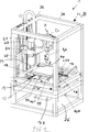
In den
Solche Vorrichtungen
Die Vorrichtung
Die Vorrichtung
Ferner ist ein Antriebssystem
In der dargestellten Ausgestaltung der Vorrichtung
Der Träger
entlang der X-Achse und der Y-Achse verfahrbar sein und der Träger
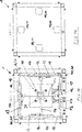
Die eingangs genannten Nachteile sind nun dadurch vermieden, dass zur Ausführung der Relativbewegung in mindestens einer der Bewegungsrichtungen mehrere Antriebsmotoren
Die Antriebsmotoren
Das jeweils einer Bewegungsrichtung zugeordnete Paar von Zahnstangen
Die Gleitschienen
Im Folgenden darf auf den Hubmechanismus
Der Hubmechanismus
In besonders bevorzugter Ausgestaltung weist der Hubmechanismus
Im Folgenden darf nun noch einmal auf die
Der Tisch
Die Vorrichtung
Auf einer Grundplatte
Die Profilstücke
Das Gehäuse
Die Vorrichtung
Die eingangs genannten Nachteile sind daher vermieden und entsprechende Vorteile sind erzielt.The aforementioned disadvantages are therefore avoided and corresponding advantages are achieved.
BezugszeichenlisteLIST OF REFERENCE NUMBERS
- 11
- Vorrichtungcontraption
- 22
- Trägercarrier
- 33
- Platteplate
- 44
- Tischtable
- 55
- Bearbeitungsvorrichtungprocessing device
- 66
- Extruderextruder
- 77
- Materialmaterial
- 88th
- Heizelementheating element
- 99
- Düsejet
- 1010
- Antriebssystemdrive system
- 1111
- Antriebsmotordrive motor
- 1212
- Zahnradgear
- 1313
- Zahnstangerack
- 1414
- Führungsschieneguide rail
- 1515
- Schlittencarriage
- 1616
- Führungsaufnahmeguide seat
- 1717
- Lagergehäusebearing housing
- 1818
- Gleitlagerbearings
- 1919
- Gleitschieneslide
- 2020
- Hubmechanismuslifting mechanism
- 2121
- Zahnstangerack
- 2222
- Führungsschieneguide rail
- 2323
- Führungsschieneguide rail
- 2424
- Hubschlittenlifting
- 2525
- Gegengewichtcounterweight
- 2626
- Führungsschieneguide rail
- 2727
- Umlenkmitteldeflecting
- 2828
- Aluminiumplattealuminum plate
- 2929
- Dämmschichtdamp course
- 3030
- Aluminiumplattealuminum plate
- 3131
- Positioniermittelpositioning
- 3232
- Tragvorrichtungcarrying device
- 3333
- Gehäusecasing
- 3434
- Profilstückprofile piece
- 3535
- Verbindungselementconnecting element
- 3636
- Grundplattebaseplate
- 3737
- Energieversorgungpower supply
- 3838
- Zwischenbodenfalse floor
- 3939
- Endschalterlimit switch
- 4040
- Endschalterlimit switch
- 4141
- Endschalterlimit switch
- 4242
- Betätigungsvorrichtungactuator
ZITATE ENTHALTEN IN DER BESCHREIBUNG QUOTES INCLUDE IN THE DESCRIPTION
Diese Liste der vom Anmelder aufgeführten Dokumente wurde automatisiert erzeugt und ist ausschließlich zur besseren Information des Lesers aufgenommen. Die Liste ist nicht Bestandteil der deutschen Patent- bzw. Gebrauchsmusteranmeldung. Das DPMA übernimmt keinerlei Haftung für etwaige Fehler oder Auslassungen.This list of the documents listed by the applicant has been generated automatically and is included solely for the better information of the reader. The list is not part of the German patent or utility model application. The DPMA assumes no liability for any errors or omissions.
Zitierte PatentliteraturCited patent literature
- US 5340433 [0004] US 5340433 [0004]
- DE 69033899 T2 [0004] DE 69033899 T2 [0004]
- DE 19524013 C2 [0006] DE 19524013 C2 [0006]
- US 5503785 A [0006] US 5503785 A [0006]
Claims (15)
Priority Applications (2)
| Application Number | Priority Date | Filing Date | Title |
|---|---|---|---|
| DE102012000664.0A DE102012000664B4 (en) | 2012-01-17 | 2012-01-17 | Device for generating three-dimensional objects |
| EP13000203.3A EP2617554A1 (en) | 2012-01-17 | 2013-01-15 | Apparatus for generating three-dimensional objects |
Applications Claiming Priority (1)
| Application Number | Priority Date | Filing Date | Title |
|---|---|---|---|
| DE102012000664.0A DE102012000664B4 (en) | 2012-01-17 | 2012-01-17 | Device for generating three-dimensional objects |
Publications (2)
| Publication Number | Publication Date |
|---|---|
| DE102012000664A1 true DE102012000664A1 (en) | 2013-07-18 |
| DE102012000664B4 DE102012000664B4 (en) | 2014-07-10 |
Family
ID=47594481
Family Applications (1)
| Application Number | Title | Priority Date | Filing Date |
|---|---|---|---|
| DE102012000664.0A Expired - Fee Related DE102012000664B4 (en) | 2012-01-17 | 2012-01-17 | Device for generating three-dimensional objects |
Country Status (2)
| Country | Link |
|---|---|
| EP (1) | EP2617554A1 (en) |
| DE (1) | DE102012000664B4 (en) |
Cited By (4)
| Publication number | Priority date | Publication date | Assignee | Title |
|---|---|---|---|---|
| CN105269815A (en) * | 2014-07-25 | 2016-01-27 | 瑞安市麦田网络科技有限公司 | 3d printer |
| WO2017108208A1 (en) | 2015-12-21 | 2017-06-29 | Wacker Chemie Ag | 3d-printing device and process for producing an object with use of a 3d-printing device |
| WO2018014948A1 (en) | 2016-07-20 | 2018-01-25 | Wacker Chemie Ag | 3d printer and method for producing objects |
| CN108746619A (en) * | 2018-07-06 | 2018-11-06 | 常德市鼎城区灌溪镇岗市建大机械厂 | A kind of 3D SMART METALSs laser print apparatus |
Families Citing this family (19)
| Publication number | Priority date | Publication date | Assignee | Title |
|---|---|---|---|---|
| CN103395209A (en) * | 2013-08-08 | 2013-11-20 | 西安非凡士机器人科技有限公司 | Large 3D printer based on FDM principles |
| CN104760424B (en) * | 2014-01-03 | 2017-01-18 | 北京理工大学 | Multifunctional assembled 3D printing device and multifunctional assembled 3D printing method |
| NL2012198C2 (en) * | 2014-02-04 | 2015-08-06 | Leapfrog B V | DEVICE FOR FORMING A WORKPIECE THROUGH 3D EXTRUSION. |
| EP3188897A1 (en) * | 2014-09-05 | 2017-07-12 | Navitracer Polska Sp. z.o.o. | Three-dimensional printing hotend and method of fitting such hotend |
| TWI574847B (en) * | 2014-10-29 | 2017-03-21 | 財團法人工業技術研究院 | Dual-nozzles printing device |
| CN104647761B (en) * | 2015-02-28 | 2016-09-21 | 济南大学 | Delta 3D printer upper support structure |
| ITRM20150111A1 (en) | 2015-03-16 | 2016-09-16 | Lorusso Alessio | MECHATRONIC HANDLING SYSTEM FOR A RAPID PROTOTYPING MACHINE |
| CN105291434A (en) * | 2015-11-04 | 2016-02-03 | 厦门强本科技有限公司 | 3D printing equipment |
| CN105500714B (en) * | 2016-01-12 | 2018-03-23 | 无锡职业技术学院 | A kind of 3D printing system of array shaping |
| FR3052375B1 (en) * | 2016-06-09 | 2019-08-23 | Compagnie Generale Des Etablissements Michelin | ADDITIVE MANUFACTURING TRAY EQUIPPED WITH STIFFENER |
| CN106071028A (en) * | 2016-07-29 | 2016-11-09 | 南京工业职业技术学院 | A kind of ice cream 3D printer |
| EP3311987A1 (en) | 2016-10-21 | 2018-04-25 | Technische Universität München | Production device for forming a three-dimensional object layer by layer |
| CN106903876B (en) * | 2017-03-29 | 2019-04-19 | 陕西恒通智能机器有限公司 | A kind of intelligent 3D printer easy to remove and without wire drawing |
| US10384396B2 (en) * | 2017-04-24 | 2019-08-20 | Desktop Metal, Inc. | System and method for moving build material using a gripper in a 3D printing system |
| CN109278297A (en) * | 2017-07-20 | 2019-01-29 | 三纬国际立体列印科技股份有限公司 | The intermittent magnetizer and its operating method of three-dimensional printing machine |
| CN108608647A (en) * | 2018-06-14 | 2018-10-02 | 重庆城雕院景观雕塑有限公司 | 3d printing work platform |
| CN109049702B (en) * | 2018-08-02 | 2021-09-10 | 西安理工大学 | 3D printing system based on 6-PSS parallel mechanism |
| WO2021066832A1 (en) * | 2019-10-03 | 2021-04-08 | Hewlett-Packard Development Company, L.P. | Printhead to print medium spacing adjusting system |
| CN114670436A (en) * | 2022-04-02 | 2022-06-28 | 上海联泰科技股份有限公司 | Lifting device for 3D printer resin tank |
Citations (5)
| Publication number | Priority date | Publication date | Assignee | Title |
|---|---|---|---|---|
| FR2583333A1 (en) * | 1985-06-14 | 1986-12-19 | Cilas Alcatel | Process for producing a model of an industrial component and device for implementing this process |
| EP0421527A1 (en) * | 1989-10-05 | 1991-04-10 | Koninklijke Philips Electronics N.V. | Two-step positioning device |
| US5340433A (en) | 1989-10-30 | 1994-08-23 | Stratasys, Inc. | Modeling apparatus for three-dimensional objects |
| US5503785A (en) | 1994-06-02 | 1996-04-02 | Stratasys, Inc. | Process of support removal for fused deposition modeling |
| DE69033899T2 (en) | 1989-07-05 | 2002-06-27 | Hitachi Maxell | disk cartridge |
Family Cites Families (2)
| Publication number | Priority date | Publication date | Assignee | Title |
|---|---|---|---|---|
| US5204124A (en) * | 1990-10-09 | 1993-04-20 | Stanley Secretan | Continuous extruded bead object fabrication apparatus |
| US5764521A (en) * | 1995-11-13 | 1998-06-09 | Stratasys Inc. | Method and apparatus for solid prototyping |
-
2012
- 2012-01-17 DE DE102012000664.0A patent/DE102012000664B4/en not_active Expired - Fee Related
-
2013
- 2013-01-15 EP EP13000203.3A patent/EP2617554A1/en not_active Withdrawn
Patent Citations (7)
| Publication number | Priority date | Publication date | Assignee | Title |
|---|---|---|---|---|
| FR2583333A1 (en) * | 1985-06-14 | 1986-12-19 | Cilas Alcatel | Process for producing a model of an industrial component and device for implementing this process |
| DE69033899T2 (en) | 1989-07-05 | 2002-06-27 | Hitachi Maxell | disk cartridge |
| EP0421527A1 (en) * | 1989-10-05 | 1991-04-10 | Koninklijke Philips Electronics N.V. | Two-step positioning device |
| US5340433A (en) | 1989-10-30 | 1994-08-23 | Stratasys, Inc. | Modeling apparatus for three-dimensional objects |
| DE69033809T2 (en) * | 1989-10-30 | 2002-04-25 | Stratasys Inc | Device and method for creating three-dimensional objects |
| US5503785A (en) | 1994-06-02 | 1996-04-02 | Stratasys, Inc. | Process of support removal for fused deposition modeling |
| DE19524013C2 (en) | 1994-06-02 | 2000-03-09 | Stratasys Inc | Method and device for removing a supporting structure in three-dimensional modeling |
Cited By (6)
| Publication number | Priority date | Publication date | Assignee | Title |
|---|---|---|---|---|
| CN105269815A (en) * | 2014-07-25 | 2016-01-27 | 瑞安市麦田网络科技有限公司 | 3d printer |
| CN105269815B (en) * | 2014-07-25 | 2018-11-02 | 瑞安市麦田网络科技有限公司 | 3d printer |
| WO2017108208A1 (en) | 2015-12-21 | 2017-06-29 | Wacker Chemie Ag | 3d-printing device and process for producing an object with use of a 3d-printing device |
| US10987856B2 (en) | 2015-12-21 | 2021-04-27 | Wacker Chemie Ag | Method and device for producing an object by using a 3D printing device |
| WO2018014948A1 (en) | 2016-07-20 | 2018-01-25 | Wacker Chemie Ag | 3d printer and method for producing objects |
| CN108746619A (en) * | 2018-07-06 | 2018-11-06 | 常德市鼎城区灌溪镇岗市建大机械厂 | A kind of 3D SMART METALSs laser print apparatus |
Also Published As
| Publication number | Publication date |
|---|---|
| EP2617554A1 (en) | 2013-07-24 |
| DE102012000664B4 (en) | 2014-07-10 |
Similar Documents
| Publication | Publication Date | Title |
|---|---|---|
| DE102012000664B4 (en) | Device for generating three-dimensional objects | |
| DE102012012412A1 (en) | Apparatus, useful for producing three-dimensional objects, includes construction material, supporting unit, and applying device for application of material, where applying device includes guided blade assembly having blades holder | |
| WO2008049384A1 (en) | Device for producing a three-dimensional object | |
| EP3020550B1 (en) | Print head and extrusion nozzle for 3d printing | |
| AT500768A1 (en) | PROCESSING FACILITY | |
| DE102012003574A1 (en) | Adjusting device for adjusting the needle valves of a hot runner injection molding device | |
| DE10300959A1 (en) | Coating device for a construction device for creating molded parts from powder material | |
| DE112009004837B4 (en) | Cutting machine with numerical control | |
| DE102008005859A1 (en) | ride | |
| EP1216787B1 (en) | Positioning device | |
| DE102015103377B4 (en) | Print head for 3D printing | |
| DE69837831T2 (en) | Table unit for positioning a sample and scanning probe microscope with such a table | |
| DE202008016620U1 (en) | Device for grinding, fine grinding and / or polishing workpieces in optical quality, in particular of spherical lens surfaces in fine optics | |
| EP3873723A1 (en) | Device for simultaneous 3d printing of a plurality of objects | |
| EP2496396B1 (en) | Closing unit for a injection moulding machine | |
| DE102010036184B4 (en) | Press | |
| EP2958752B1 (en) | Surface machining device | |
| EP3030370B1 (en) | Panel-dividing system | |
| AT513338B1 (en) | Adjustment device for a motor vehicle headlight and motor vehicle headlight | |
| EP2380739B1 (en) | Printing stencil positioning arrangement for a screen printing unit | |
| DE102019007941B4 (en) | Device for producing a three-dimensional object | |
| EP3557111B1 (en) | Positioning device for alignments of heavy components | |
| EP2371482A1 (en) | Machine tool | |
| DE102008020252A1 (en) | Computer-numerical-controlled machine tool, e.g. to operate as a cutter with a spindle, has a machine body, drive elements, sliding elements and a servomotor | |
| DE102016123837A1 (en) | Locker Elvers plate |
Legal Events
| Date | Code | Title | Description |
|---|---|---|---|
| R012 | Request for examination validly filed | ||
| R016 | Response to examination communication | ||
| R016 | Response to examination communication | ||
| R016 | Response to examination communication | ||
| R016 | Response to examination communication | ||
| R018 | Grant decision by examination section/examining division | ||
| R020 | Patent grant now final | ||
| R119 | Application deemed withdrawn, or ip right lapsed, due to non-payment of renewal fee |