DE102011012710A1 - Fast identification and generation of process models - Google Patents
Fast identification and generation of process models Download PDFInfo
- Publication number
- DE102011012710A1 DE102011012710A1 DE102011012710A DE102011012710A DE102011012710A1 DE 102011012710 A1 DE102011012710 A1 DE 102011012710A1 DE 102011012710 A DE102011012710 A DE 102011012710A DE 102011012710 A DE102011012710 A DE 102011012710A DE 102011012710 A1 DE102011012710 A1 DE 102011012710A1
- Authority
- DE
- Germany
- Prior art keywords
- variable
- slew rate
- time
- determined
- change
- Prior art date
- Legal status (The legal status is an assumption and is not a legal conclusion. Google has not performed a legal analysis and makes no representation as to the accuracy of the status listed.)
- Pending
Links
- 238000000034 method Methods 0.000 title claims abstract description 936
- 230000008569 process Effects 0.000 title claims abstract description 837
- 230000008859 change Effects 0.000 claims abstract description 132
- 230000004044 response Effects 0.000 claims abstract description 94
- 238000004088 simulation Methods 0.000 claims abstract description 51
- 230000003111 delayed effect Effects 0.000 claims description 16
- 230000001934 delay Effects 0.000 claims description 5
- 238000013480 data collection Methods 0.000 claims description 2
- 238000004886 process control Methods 0.000 abstract description 30
- 230000006870 function Effects 0.000 description 26
- 238000006243 chemical reaction Methods 0.000 description 12
- 238000001514 detection method Methods 0.000 description 11
- 230000003044 adaptive effect Effects 0.000 description 10
- 238000012360 testing method Methods 0.000 description 9
- 238000004891 communication Methods 0.000 description 8
- 239000000126 substance Substances 0.000 description 6
- 238000004364 calculation method Methods 0.000 description 5
- 238000010586 diagram Methods 0.000 description 5
- 238000005259 measurement Methods 0.000 description 5
- 238000011112 process operation Methods 0.000 description 5
- 230000001276 controlling effect Effects 0.000 description 4
- 238000011161 development Methods 0.000 description 4
- 230000035484 reaction time Effects 0.000 description 4
- 230000001133 acceleration Effects 0.000 description 3
- 230000008901 benefit Effects 0.000 description 3
- 238000011217 control strategy Methods 0.000 description 3
- 230000007423 decrease Effects 0.000 description 3
- 230000000694 effects Effects 0.000 description 3
- 238000010923 batch production Methods 0.000 description 2
- 230000010354 integration Effects 0.000 description 2
- 238000004519 manufacturing process Methods 0.000 description 2
- 230000000284 resting effect Effects 0.000 description 2
- 238000003860 storage Methods 0.000 description 2
- BUHVIAUBTBOHAG-FOYDDCNASA-N (2r,3r,4s,5r)-2-[6-[[2-(3,5-dimethoxyphenyl)-2-(2-methylphenyl)ethyl]amino]purin-9-yl]-5-(hydroxymethyl)oxolane-3,4-diol Chemical compound COC1=CC(OC)=CC(C(CNC=2C=3N=CN(C=3N=CN=2)[C@H]2[C@@H]([C@H](O)[C@@H](CO)O2)O)C=2C(=CC=CC=2)C)=C1 BUHVIAUBTBOHAG-FOYDDCNASA-N 0.000 description 1
- 238000012369 In process control Methods 0.000 description 1
- 230000009471 action Effects 0.000 description 1
- 238000007792 addition Methods 0.000 description 1
- 230000003321 amplification Effects 0.000 description 1
- 238000013459 approach Methods 0.000 description 1
- 238000013528 artificial neural network Methods 0.000 description 1
- 238000004422 calculation algorithm Methods 0.000 description 1
- 238000010924 continuous production Methods 0.000 description 1
- 238000013461 design Methods 0.000 description 1
- 239000012530 fluid Substances 0.000 description 1
- 238000010965 in-process control Methods 0.000 description 1
- 238000012905 input function Methods 0.000 description 1
- 238000011835 investigation Methods 0.000 description 1
- 239000000463 material Substances 0.000 description 1
- 230000007246 mechanism Effects 0.000 description 1
- 239000002480 mineral oil Substances 0.000 description 1
- 235000010446 mineral oil Nutrition 0.000 description 1
- 238000003199 nucleic acid amplification method Methods 0.000 description 1
- 238000004540 process dynamic Methods 0.000 description 1
- 238000012545 processing Methods 0.000 description 1
- 230000001105 regulatory effect Effects 0.000 description 1
- 230000002787 reinforcement Effects 0.000 description 1
- 238000010963 scalable process Methods 0.000 description 1
- 230000001629 suppression Effects 0.000 description 1
- 230000001052 transient effect Effects 0.000 description 1
- 230000007704 transition Effects 0.000 description 1
Images


Classifications
-
- G—PHYSICS
- G05—CONTROLLING; REGULATING
- G05B—CONTROL OR REGULATING SYSTEMS IN GENERAL; FUNCTIONAL ELEMENTS OF SUCH SYSTEMS; MONITORING OR TESTING ARRANGEMENTS FOR SUCH SYSTEMS OR ELEMENTS
- G05B13/00—Adaptive control systems, i.e. systems automatically adjusting themselves to have a performance which is optimum according to some preassigned criterion
- G05B13/02—Adaptive control systems, i.e. systems automatically adjusting themselves to have a performance which is optimum according to some preassigned criterion electric
- G05B13/04—Adaptive control systems, i.e. systems automatically adjusting themselves to have a performance which is optimum according to some preassigned criterion electric involving the use of models or simulators
- G05B13/042—Adaptive control systems, i.e. systems automatically adjusting themselves to have a performance which is optimum according to some preassigned criterion electric involving the use of models or simulators in which a parameter or coefficient is automatically adjusted to optimise the performance
-
- G—PHYSICS
- G05—CONTROLLING; REGULATING
- G05B—CONTROL OR REGULATING SYSTEMS IN GENERAL; FUNCTIONAL ELEMENTS OF SUCH SYSTEMS; MONITORING OR TESTING ARRANGEMENTS FOR SUCH SYSTEMS OR ELEMENTS
- G05B11/00—Automatic controllers
- G05B11/01—Automatic controllers electric
- G05B11/36—Automatic controllers electric with provision for obtaining particular characteristics, e.g. proportional, integral, differential
- G05B11/42—Automatic controllers electric with provision for obtaining particular characteristics, e.g. proportional, integral, differential for obtaining a characteristic which is both proportional and time-dependent, e.g. P.I., P.I.D.
-
- G—PHYSICS
- G05—CONTROLLING; REGULATING
- G05B—CONTROL OR REGULATING SYSTEMS IN GENERAL; FUNCTIONAL ELEMENTS OF SUCH SYSTEMS; MONITORING OR TESTING ARRANGEMENTS FOR SUCH SYSTEMS OR ELEMENTS
- G05B17/00—Systems involving the use of models or simulators of said systems
- G05B17/02—Systems involving the use of models or simulators of said systems electric
-
- G—PHYSICS
- G05—CONTROLLING; REGULATING
- G05B—CONTROL OR REGULATING SYSTEMS IN GENERAL; FUNCTIONAL ELEMENTS OF SUCH SYSTEMS; MONITORING OR TESTING ARRANGEMENTS FOR SUCH SYSTEMS OR ELEMENTS
- G05B13/00—Adaptive control systems, i.e. systems automatically adjusting themselves to have a performance which is optimum according to some preassigned criterion
- G05B13/02—Adaptive control systems, i.e. systems automatically adjusting themselves to have a performance which is optimum according to some preassigned criterion electric
- G05B13/04—Adaptive control systems, i.e. systems automatically adjusting themselves to have a performance which is optimum according to some preassigned criterion electric involving the use of models or simulators
Landscapes
- Engineering & Computer Science (AREA)
- Physics & Mathematics (AREA)
- General Physics & Mathematics (AREA)
- Automation & Control Theory (AREA)
- Health & Medical Sciences (AREA)
- Artificial Intelligence (AREA)
- Computer Vision & Pattern Recognition (AREA)
- Evolutionary Computation (AREA)
- Medical Informatics (AREA)
- Software Systems (AREA)
- Feedback Control In General (AREA)
- Testing And Monitoring For Control Systems (AREA)
Abstract
Ein Verfahren zum schnellen Identifizieren von Prozessmodellen identifiziert innerhalb einer relativ kurzen Zeitspanne die dynamische Beziehung zwischen einem Prozesseingang und einem Prozessausgang, indem es aus der anfänglichen Reaktion des Prozessausgangs auf eine Veränderung des Prozesseingangs eine Schätzung einer integrierenden Verstärkung und einer Prozessstillstandszeit entwickelt. Die Werte der integrierenden Verstärkung und der Stillstandszeit werden dann dazu benutzt, ein vollständiges Prozessmodell für einen beliebigen von vielen unterschiedlichen Prozesstypen zu erzeugen. Diese Prozessmodelle können sehr schnell eine Prozesssimulation durchführen oder können zu Steuerzwecken benutzt werden, um es zu ermöglichen, ein Prozesssteuerungssystem bereitzustellen, das Prozessmodelle während eines On-Line-Prozesses wesentlich schneller benutzt oder darauf zugreift, als dies in der Vergangenheit möglich war. Außerdem lässt sich dieses schnelle Modellierungsverfahren dazu benutzen, ein Simulationsmodell für eine Prozessschleife zu entwickeln, bevor die Steuereinrichtung, die die Prozessschleife steuert, die Reaktion auf eine einzelne Prozessabweichung oder Sollwertänderung abgeschlossen hat, was das Verfahren sehr nützlich für die Steuerung langsamer Prozesse macht.A method for quickly identifying process models identifies, within a relatively short amount of time, the dynamic relationship between a process input and a process output by developing an estimate of integral gain and process downtime from the initial response of the process output to a change in process input. The integrating gain and downtime values are then used to generate a complete process model for any one of many different process types. These process models may very quickly perform process simulation or may be used for control purposes to enable a process control system to be used that accesses or accesses process models much more quickly than was possible in the past during an on-line process. In addition, this rapid modeling technique can be used to develop a simulation model for a process loop before the controller that controls the process loop has completed the response to a single process deviation or setpoint change, making the method very useful for controlling slow processes.
Description
VERWANDTE ANMELDUNGENRELATED APPLICATIONS
Die vorliegende Anmeldung ist eine regulär eingereichte Anmeldung der am 2. März 2010 eingereichten vorläufigen US-Patentanmeldung Nr. 61/309,737 namens „Rapid Process Model Identification and Generation” und beansprucht deren Priorität und deren Vorteil des Einreichungsdatums, wobei deren gesamte Offenbarung hiermit ausdrücklich in den vorliegenden Gegenstand mit einbezogen wird.The present application is a regularly filed application of US Provisional Application No. 61 / 309,737, filed on Mar. 2, 2010, entitled "Rapid Process Model Identification and Generation" and claims its priority and benefit of the filing date, the entire disclosure of which is expressly incorporated herein by reference the present subject matter is included.
TECHNISCHES GEBIETTECHNICAL AREA
Die vorliegende Erfindung betrifft allgemein Prozesssteuerungssysteme und insbesondere ein Verfahren zum schnellen Identifizieren und Erzeugen von Prozessmodellen zur Verwendung in Steuerungs- und Simulationsaktivitäten in Prozesssteuerungssystemen wie z. B. industriellen Prozessanlagen.The present invention relates generally to process control systems, and more particularly to a method for quickly identifying and creating process models for use in control and simulation activities in process control systems, such as process control systems. B. industrial process equipment.
BESCHREIBUNG DER VERWANDTEN TECHNIKDESCRIPTION OF THE RELATED TECHNIQUE
Prozesssteuerungssysteme wie z. B. verteilte oder skalierbare Prozesssteuerungssysteme, wie sie in Steuerungsanlagen für chemische oder mineralölbezogene Prozesse verwendet werden, weisen typischerweise eine oder mehrere Prozesssteuerungen und Eingangs-/Ausgangs-(E/A)-Vorrichtungen auf, die über Analog-, Digital- oder kombinierte Analog/Digital-Busse kommunizierend miteinander oder mit mindestens einem Host- oder Bedienerarbeitsplatzrechner und einer oder mehreren Arbeitsbereichsvorrichtungen verbunden sind. Die Arbeitsbereichsvorrichtungen, bei denen es sich beispielsweise um Ventile, Ventilstellungsregler, Schalter und Messwertgeber (z. B. Temperatur-, Druck- und Durchflusssensoren) handelt, führen innerhalb des Prozesses Funktionen wie das Öffnen und Schließen von Ventilen und das Messen von Prozessparametern aus. Die Prozesssteuerung empfängt Signale, die Prozessmessungen anzeigen, welche von den Arbeitsbereichsvorrichtungen vorgenommen wurden, und/oder andere Informationen zu den Arbeitsbereichsvorrichtungen, verwenden diese Informationen dazu, eine Steuerroutine zu implementieren, und erzeugt dann Steuersignale, die über die Busse oder andere Kommunikationsleitungen an die Arbeitsbereichsvorrichtungen gesendet werden, um den Prozessbetrieb zu steuern. Informationen von den Arbeitsbereichsvorrichtungen und der Steuereinrichtung werden typischerweise einer oder mehreren Anwendungen zur Verfügung gestellt, die vom Bedienerarbeitsplatzrechner ausgeführt werden, um es einem Bediener zu ermöglichen, jede gewünschte Funktion im Zusammenhang mit dem Prozess auszuführen, z. B. den aktuellen Status des Prozesses aufzurufen, den Prozessbetrieb zu modifizieren usw.Process control systems such. Distributed or scalable process control systems, such as used in chemical or mineral oil related control systems, typically include one or more process controllers and input / output (I / O) devices that can be controlled by analog, digital, or combined analog / Digital buses communicating with each other or connected to at least one host or operator workstation and one or more workspace devices. The workspace devices, which include valves, valve positioners, switches, and transducers (eg, temperature, pressure, and flow), perform functions such as opening and closing valves and measuring process parameters within the process. The process controller receives signals indicative of process measurements made by the work area devices and / or other information about the work area devices, uses that information to implement a control routine, and then generates control signals to the work area devices via the buses or other communication lines be sent to control the process operation. Information from the work area devices and the controller is typically provided to one or more applications that are executed by the operator workstation to allow an operator to perform any desired function associated with the process, e.g. For example, call the current state of the process, modify the process operation, and so on.
Einige Prozesssteuerungssysteme wie z. B. das System DeltaV®, das von Emerson Process Management vertrieben wird, verwenden Funktionsblöcke oder Gruppen von Funktionsblöcken, die als Module bezeichnet werden und in der Steuereinrichtung oder in verschiedenen Arbeitsbereichsvorrichtungen angeordnet sind, um Steuervorgänge auszuführen. In diesen Fällen sind die Steuereinrichtung oder andere Einrichtungen dazu in der Lage einen oder mehrere Funktionsblöcke oder Module auszuführen, welche jeweils Eingänge an andere Funktionsblöcke (entweder innerhalb derselben Vorrichtung oder in unterschiedlichen Vorrichtungen) bereitstellen und/oder Ausgänge von diesen empfangen und einige Prozessvorgänge durchführen, z. B. das Messen oder Detektieren eines Prozessparameters, das Steuern einer Vorrichtung oder das Durchführen eines Steuervorgangs wie z. B. der Implementierung eines Proportional-integral-derivativ-(PID)-Steuerungsprogramms. Die verschiedenen Funktionsblöcke und Module innerhalb eines Prozesssteuerungssystems sind allgemein dazu konfiguriert, miteinander (z. B. über einen Bus) zu kommunizieren, um eine oder mehrere Prozesssteuerschleifen zu bilden.Some process control systems such. For example, the DeltaV system ®, sold by Emerson Process Management, use function blocks or groups of function blocks referred to as modules, and are arranged in the controller or in different work area devices to perform control operations. In these cases, the controller or other devices are capable of executing one or more functional blocks or modules, each providing inputs to and / or receiving outputs from other functional blocks (either within the same device or in different devices) and performing some process operations, z. B. measuring or detecting a process parameter, controlling a device or performing a control process such. The implementation of a Proportional Integral Derivative (PID) control program. The various functional blocks and modules within a process control system are generally configured to communicate with each other (eg, via a bus) to form one or more process control loops.
Prozesssteuereinrichtungen sind typischerweise dazu programmiert, für eine Anzahl unterschiedlicher Schleifen, die für einen Prozess definiert sind oder darin enthalten sind, z. B. Ablaufregelschleifen, Temperaturregelschleifen, Drucksteuerschleifen usw., jeweils einen unterschiedlichen Algorithmus, ein unterschiedliches Unterprogramm oder eine unterschiedliche Steuerschleife auszuführen. Allgemein ausgedrückt enthält jede derartige Steuerschleife einen oder mehrere Eingangsblöcke, wie z. B. einen Analogeingangs-(AE)-Funktionsblock, einen Einzelausgangs-Steuerungsblock wie z. B. einen Proportional-integral-derivativ-(PID)- oder Fuzzy-Logic-Steuerungsfunktionsblock und einen Ausgangsblock wie z. B. einen Analogausgangs-(AA)-Funktionsblock.Process controllers are typically programmed to handle a number of different loops defined or included in a process, e.g. Flow control loops, temperature control loops, pressure control loops, etc., each to execute a different algorithm, a different subroutine, or a different control loop. In general terms, each such control loop contains one or more input blocks, such as input blocks. B. an analog input (AE) function block, a single output control block such. A proportional integral derivative (PID) or fuzzy logic control function block, and an output block such as An analog output (AA) function block.
Steuerprogramme und die Funktionsblöcke, die diese Programme implementieren, sind gemäß einer Anzahl von Steuerverfahren konfiguriert, darunter PID-Steuerung, Fuzzy-Logic-Steuerung und modellbasierte Verfahren wie z. B. einen Smith Predictor oder eine Model Predictive Control (modellprädiktive Regelung, MPC). Bei modellbasierten Steuerverfahren beruhen die Parameter, die in den Programmen zur Bestimmung der Steuerungsreaktion der geschlossenen Regelschleifen benutzt werden, auf der dynamischen Prozessreaktion auf Veränderungen in den manipulierten oder gemessenen Störungen, die als Eingänge für die Prozesse dienen. Eine Darstellung dieser Reaktion des Prozesses auf Veränderungen der Prozesseingänge kann als ein Prozessmodell charakterisiert werden. Beispielsweise kann ein parametrisiertes Prozessmodell erster Ordnung Werte für die Verstärkungskonstante, die Stillstandszeitkonstante und die dominierende Zeitkonstante festlegen.Control programs and the functional blocks that implement these programs are configured according to a number of control methods, including PID control, fuzzy logic control, and model-based techniques such as control logic. As a Smith Predictor or a model predictive control (model predictive control, MPC). In model-based control methods, the parameters used in the programs to determine closed-loop control response are based on the dynamic process response to changes in the manipulated or measured disturbances that serve as inputs to the processes. A representation of this reaction of the process to changes in the process inputs can be characterized as a process model. For example, a parameterized first-order process model may set values for the gain constant, the standstill time constant, and the dominant time constant.
Bei MPC handelt es sich um einen bestimmten Typ des modellbasierten Verfahrens, und es beinhaltet eine Anzahl von Schritt- oder Impulsantwortmodellen, die dazu ausgelegt sind, die dynamischen Beziehungen zwischen Prozesseingängen und -ausgängen zu erfassen. Bei MPC-Verfahren wird das Prozessmodell unmittelbar dazu benutzt, die Steuereinrichtung zu erzeugen. Bei Verwendung in Verbindung mit Prozessen, die während der Prozessstillstandszeit großen Veränderungen, Prozessverzögerungen usw. unterliegen, muss die MPC-Steuereinrichtung automatisch neu erzeugt werden, um mit den aktuellen Prozessbedingungen übereinzustimmen. In diesen Fällen wird daher für jede von einer Anzahl von Betriebsbedingungen ein Prozessmodell identifiziert. Das Einbringen einer Vielzahl von Prozessmodellen und die erforderliche automatische Erzeugung der Steuereinrichtung zwecks Übereinstimmung mit den aktuellen Prozessbedingungen erhöht jedoch die Komplexität der Prozesssteuerungssysteme in unerwünschter Weise.MPC is a particular type of model-based method and includes a number of step or impulse response models that are designed to capture the dynamic relationships between process inputs and outputs. In MPC methods, the process model is used directly to generate the controller. When used in conjunction with processes that are subject to large changes, process delays, etc. during process downtime, the MPC controller must be automatically recreated to match current process conditions. In these cases, therefore, a process model is identified for each of a number of operating conditions. However, the introduction of a variety of process models and the required automatic generation of the controller for compliance with current process conditions undesirably increases the complexity of the process control systems.
Prozessmodelle wurden auch dazu benutzt, Abstimmungsparameter von PID und anderen Steuermethoden anhand von adaptiven Steuerverfahren einzustellen, wobei die Abstimmung der PID-(oder anderen)Steuereinrichtung im Allgemeinen aufgrund von Veränderungen im Prozessmodell und einer vom Benutzer ausgewählten Abstimmungsregel aktualisiert wird. So offenbaren beispielsweise die
Trotz der Aussicht auf eine gesteigerte Steuerungsleistung ist die Nutzung modellbasierter Steuerverfahren und adaptiver Steuerverfahren in der Prozessindustrie bislang beschränkt, da die Verfahren häufig schwierig in der Praxis zu implementieren waren. In praktischer Hinsicht war die Modellidentifikation bislang typischerweise ein Teil eines speziellen Funktionsblocks, der speziell für die MPC-Steuerung oder adaptive Steuerung ausgelegt war. Leider ist es häufig schwierig zu ermitteln, welche Prozessregelschleifen von der Implementierung einer adaptiven Steuerung profitieren würden, d. h., welche Schleifen für die adaptive Steuerfunktion ausgewählt werden sollten. Einen Grund stellt die schiere Anzahl der Regelschleifen (mehrere Hundert) und Instrumente (mehrere Tausend) dar, die in einer typischen Anlage überwacht werden. Unabhängig von Größe oder Komplexität der Anlage unterstützen übliche Prozesssteuerungssysteme typischerweise nicht die Erzeugung von Prozessmodelle für alle Steuerschleifen in der Anlage. Verschlimmernd kommt hinzu, dass umfangreiche Prüfungen notwendig sind, um neue Prozessmodelle für jede einzelne Steuerschleife zu identifizieren, für die ein Modell ermittelt werden soll. Bei Prüfungen dieser Art kann es beispielsweise notwendig sein, eine oder mehrere Prozessstörungen anzuwenden, die sich nicht mit dem Betrieb eines laufenden Prozesses vertragen.Despite the prospect of increased control performance, the use of model-based control methods and adaptive control methods in the process industry has hitherto been limited, as the methods were often difficult to implement in practice. In practical terms, model identification has typically been part of a special functional block designed specifically for MPC control or adaptive control. Unfortunately, it is often difficult to determine which process loops would benefit from the implementation of adaptive control, i. that is, which loops should be selected for the adaptive control function. One reason is the sheer number of control loops (several hundred) and instruments (several thousand) that are monitored in a typical facility. Regardless of the size or complexity of the plant, conventional process control systems typically do not support the generation of process models for all control loops in the plant. To make matters worse, extensive testing is needed to identify new process models for each individual control loop for which a model is to be determined. In tests of this kind, it may be necessary, for example, to apply one or more process disturbances that are not compatible with the operation of an ongoing process.
Wie oben erwähnt, kann das Entwickeln von Prozessmodellen zur Verwendung in Steuerungssystemen ein Prozess sein, der manuelles Eingreifen erfordert, und dessen Durchführung auch im Falle einer Automatisierung mit einem hohen Zeitaufwand verbunden ist. Im Allgemeinen wird zur Entwicklung eines Prozessmodells für eine Regelschleife ein Prozess zur Abweichung gebracht oder ein Steuersignal geändert, woraufhin die Reaktionen der Prozessvariablen überwacht werden, um die Prozessreaktionszeit, die Prozessverstärkung, die Prozessstillstandszeit usw. für die Prozessschleife zu ermitteln. Dieses Verfahren kann dazu verwendet werden, die Dynamik schneller Prozesse oder schneller Prozessschleifen, z. B. von Durchfluss- oder Flüssigkeitsdruck-Regelschleifen, auf rasche und einfache Weise zu ermitteln, da die Zeit, die eine Prozessvariable benötigt, um für diese Schleifen ihren Ruhewert zu erreichen, innerhalb von Sekunden abläuft, was eine rasche Identifikation der Prozessdynamik anhand einer breiten Spanne von Verfahren ermöglicht. Bei langsamen Prozessen oder Prozessschleifen beispielsweise auf der Behälter- oder Säulenebene, bei Temperatur-, pH- und Zusammensetzungsregelschleifen, kann es Minuten, Stunden oder sogar Tage dauern, bis die relevante Prozessvariable einen Sollwert oder einen abschließenden Ruhewert erreicht. Außerdem treten Störungen häufig vor dem Abschluss der Prüfung auf, was weitere Prüfungen notwendig macht. Aus diesem Grund benötigen gegenwärtige Modellidentifikationswerkzeuge für diese Prozesse typischerweise sogar bei relativ ruhigen Prozessen eine Vielzahl von Prüfungen. Es kann daher Tage oder sogar Wochen dauern, bis ein vollständiger oder präziser Modellsatz für langsame Prozessschleifen identifiziert wurde.As mentioned above, the development of process models for use in control systems may be a process that requires manual intervention and is time consuming to perform even in the case of automation. Generally, to develop a process model for a closed loop, a process is brought to a bias or a control signal is changed, whereupon the responses of the process variables are monitored to determine the process response time, process gain, process down time, etc. for the process loop. This method can be used to increase the dynamics of faster processes or faster process loops, e.g. As of flow or fluid pressure control loops to determine in a quick and easy way, since the time it takes a process variable to reach for these loops their quiescent value, within seconds, which is a rapid identification of the process dynamics on the basis of a wide Range of procedures. For slow processes or process loops, for example, at the vessel or column level, temperature, pH, and composition loops, it may take minutes, hours, or even days for the relevant process variable to reach a setpoint or final resting value. In addition, faults often occur before the completion of the test, which requires further testing. For this reason, current model identification tools typically require a variety of checks for these processes, even with relatively quiet processes. It may therefore take days or even weeks for a complete or accurate model set to be identified for slow process loops.
Bei kontinuierlichen Prozessen ändern sich Sollwerte zudem relativ selten und werden während des normalen Ablaufs allgemein nur beim Hochfahren des Prozesses oder bei Ratenänderungen oder graduellen Übergängen erstellt. Bei Chargenprozessen liegen darüber hinaus in eine Chargenvariable normalerweise nur ein oder zwei Sollwertänderungen wie z. B. Temperatur vor. Daher ist es schwierig, die Vielzahl an Prüfungen durchzuführen, die zum Entwickeln eines Modells für diese Schleifen notwendig ist. Aus den oben genannten Gründen sind daher die meisten existierenden Prozessmodell-Identifikationswerkzeuge der modellprädiktiven Steuerung und adaptiven proportionalen, integralen, derivativen (PID) Steuereinrichtungen oder PID-Auto-Tunern zugeordnet, und werden im Allgemeinen nicht für die Regelschleifen langsamer Prozesse angewandt. In continuous processes, setpoints also change relatively seldom and are generally created during normal operation only at the startup of the process or at rate changes or gradual transitions. In batch processes, moreover, in a batch variable usually only one or two setpoint changes such. B. temperature before. Therefore, it is difficult to perform the plurality of tests necessary to develop a model for these loops. For the reasons stated above, therefore, most existing process model identification tools are associated with model predictive control and adaptive proportional, integral derivative (PID) controllers or PID auto-tuners, and are generally not applied to the slow-process control loops.
KURZDARSTELLUNGSUMMARY
Ein schnelles Prozessmodell-Identifikationsverfahren identifiziert innerhalb einer relativ kurzen Zeitspanne von beispielsweise Minuten das dynamische Verhältnis zwischen einem Prozesseingang und einem Prozessausgang, und zwar auch bei langsamen Prozessen und Prozessschleifen. Dieses Modellidentifikationsverfahren kann dann dazu benutzt werden, Prozessmodelle für viele verschiedene Typen von Prozessen zu erzeugen, und kann zu Steuerzwecken benutzt werden, um es beispielsweise zu ermöglichen, ein Prozesssteuerungssystem bereitzustellen, das Prozessmodelle während eines On-Line-Prozesses wesentlich schneller benutzt oder darauf zugreift, als dies in der Vergangenheit möglich war. Außerdem lässt sich dieses Verfahren dazu benutzen, ein Simulationssystem für eine Prozessschleife zu entwickeln, bevor die Steuereinrichtung, die die Prozessschleife steuert, die Reaktion auf eine einzelne Prozessabweichung oder Sollwertänderung abgeschlossen hat. Dieses Merkmal erlaubt es, das schnell erzeugte Modell in Reaktion auf die Prozessabweichung, die zum Erzeugen des Modells benutzt wurde, zum Steuern von Prozessen zu verwenden, also z. B. vor dem Ablauf einer Prozessreaktionszeitdauer des Prozesses oder bevor eine Prozesssteuereinrichtung den Prozess so geregelt hat, dass er einen Dauerzustand in Reaktion auf die Prozessabweichung erreicht hat (die von einer Veränderung einer manipulierten Variable innerhalb des Prozesses verursacht worden sein kann). In jedem Fall lässt sich das Prozessmodell-Identifikationsverfahren dazu benutzen, rasch anfängliche Prozessmodelle zu ermitteln, die sofort dazu benutzt werden können, eine Prozesssteuerung und Simulation für den Prozess durchzuführen, und die aktualisiert, modifiziert oder verfeinert werden können, sobald mehr Daten zu den Prozessschleifen verfügbar sind oder im Laufe der Zeit verfügbar werden.A fast process model identification process identifies the dynamic relationship between a process input and a process output within a relatively short time, such as minutes, even with slow processes and process loops. This model identification method can then be used to create process models for many different types of processes and can be used for control purposes, for example, to provide a process control system that uses or accesses process models much faster during an on-line process than was possible in the past. In addition, this method can be used to develop a process loop simulation system before the controller that controls the process loop has completed the response to a single process offset or set point change. This feature allows the fast model to be used to control processes in response to the process variance used to create the model, e.g. Before the expiration of a process response time period of the process or before a process controller has regulated the process to have reached a steady state in response to the process deviation (which may have been caused by a manipulated variable change within the process). In any case, the process model identification method can be used to quickly identify initial process models that can be used immediately to perform process control and simulation for the process, and that can be updated, modified, or refined as more data is added to the process loops are available or become available over time.
In einem Fall beinhaltet ein Verfahren zum Erzeugen eines Prozessmodells für einen Prozess das Sammeln von Prozessdaten in Bezug auf eine Prozessvariable und eine manipulierte Variable im Prozess und, nach einer Veränderung der manipulierten Variable, das Ermitteln einer Anstiegsrate im Zusammenhang mit der Prozessvariable aus den gesammelten Prozessdaten, die innerhalb einer bestimmten Zeitspanne erzeugt wurden. Dabei ist die bestimmte Zeitspanne kürzer als die Prozessreaktionszeit im Zusammenhang mit dem Prozess und liegt wenigstens teilweise nach dem Ende einer Stillstandszeit im Zusammenhang mit dem Prozess. Das Verfahren erzeugt dann anhand der ermittelten Anstiegsrate ein Prozessmodell für den Prozess. Das Verfahren kann ferner das Schätzen einer Prozessstillstandszeit im Zusammenhang mit dem Prozess aus den gesammelten Prozessdaten beinhalten, und es kann die geschätzte Prozessstillstandszeit zusätzlich zur Anstiegsrate verwenden, um das Prozessmodell zu erzeugen. Das Verfahren kann die Anstiegsrate im Zusammenhang mit der Prozessvariable ermitteln, indem es eine Veränderung der Prozessvariablen im Verlauf der bestimmten Zeitspanne ermittelt, wobei die Länge der bestimmten Zeitspanne mit einer geschätzten Prozessstillstandszeit des Prozesses in Verbindung steht. Die Länge der bestimmten Zeitspanne kann beispielsweise gleich der geschätzten Prozessstillstandszeit sein, oder sie kann ein Vielfaches der geschätzten Prozessstillstandszeit sein.In one instance, a method for generating a process model for a process includes collecting process data related to a process variable and a manipulated variable in the process, and, after a change in the manipulated variable, determining a slew rate associated with the process variable from the collected process data that were generated within a certain period of time. In this case, the determined period of time is shorter than the process reaction time associated with the process and is at least partially related to the process after the end of a downtime. The method then generates a process model for the process based on the determined rate of increase. The method may further include estimating a process down time associated with the process from the collected process data, and may use the estimated process downtime in addition to the ramp rate to generate the process model. The method may determine the slew rate associated with the process variable by determining a change in the process variable over the determined amount of time, wherein the length of the determined amount of time is associated with an estimated process stoppage time of the process. For example, the length of the determined period of time may be equal to the estimated process down time, or it may be a multiple of the estimated process downtime.
In einigen Fällen tritt diese bestimmte Zeitspanne (wenigstens teilweise) innerhalb eines Zeitrahmens ein, der am Ende der Stillstandszeit beginnt und sich über eine Zeitspanne z. B. gleich oder unter dem Zehnfachen der Prozessstillstandszeit nach dem Ende der Stillstandszeit erstreckt. Allgemeiner tritt die bestimmte Zeitspanne kurz oder unmittelbar nach dem Ende der Prozessstillstandszeit des Prozesses ein (nach einer Veränderung der manipulierten Variable). In einigen Fällen kann die bestimmte Zeitspanne innerhalb einer Zeitspanne liegen, die sich über die Länge einer oder einiger Stillstandszeiten des Prozesses nach dem Ende der Prozessstillstandszeit erstreckt, sie kann innerhalb der ersten Hälfte der Prozessreaktionszeit des Prozesses liegen, oder sie kann bei stillstandszeitdominierten Prozessen in einer längeren Zeitspanne als dieser liegen. Die bestimmte Zeitspanne ist jedoch stets weniger als die Prozessreaktionszeit des Prozesses im Zusammenhang mit einer Veränderung der manipulierten Variablen.In some cases, this particular period of time (at least in part) occurs within a time frame that begins at the end of the downtime and continues over a period of time, e.g. B. equal to or less than ten times the process downtime after the end of the downtime extends. More generally, the certain amount of time occurs shortly after the end of the process stoppage time of the process (after a change in the manipulated variable). In some cases, the particular amount of time may be within a length of time that extends over the length of one or more downtime of the process after the end of the process downtime, may be within the first half of the process response time of the process, or may be in a downtime dominated process longer than this time. However, the determined amount of time is always less than the process response time of the process associated with a change in the manipulated variable.
Das Erzeugen eines Prozessmodells für den Prozess kann das Ermitteln einer integrierenden Verstärkung des Prozesses aus der ermittelten Anstiegsrate beinhalten, indem ein Verhältnis der ermittelten Anstiegsrate zu der Veränderung der manipulierten Variable ermittelt wird. Außerdem kann das Verfahren die für den Prozess ermittelte integrierenden Verstärkung dazu benutzen, andere Prozessmodellparameter für den Prozess zu ermitteln, und kann die Prozessmodellparameter dazu benutzen, den Prozessbetrieb vor dem Ende der Prozessreaktionszeit zu simulieren. Das Verfahren kann die Prozessmodellparameter auch oder alternativ dazu benutzen, Steuerparameter zum Steuern des Prozesses zu ermitteln, und kann die Steuerparameter dazu benutzen, den Prozess vor dem Ende der Prozessreaktionszeit zu steuern.Generating a process model for the process may include determining an integrating gain of the process from the determined slew rate by determining a ratio of the determined slew rate to the manipulated variable change. In addition, the method can be used for the Use the process-finding integrating gain to determine other process model parameters for the process, and use the process model parameters to simulate process operation before the end of the process response time. The method may also or alternatively use the process model parameters to determine control parameters for controlling the process, and may use the control parameters to control the process before the end of the process response time.
Ferner kann das Verfahren die Anstiegsrate im Zusammenhang mit der Prozessvariable nach einer Veränderung der manipulierten Variable ermitteln, indem es eine Vielzahl von Werten einer Prozessvariablen-Anstiegsrate im Verlauf unterschiedlicher Zeiträume gleicher Länge ermittelt (z. B. einer Zeit gleich der Länge der geschätzten Prozessstillstandszeit), und kann die Anstiegsrate als statistisches Maß der Vielzahl von Werten der Prozessvariablen-Anstiegsrate ermitteln. Beispielsweise kann das Verfahren die Anstiegsrate als ein Maximum, einen Mittelwert, einen Medianwert usw. der Vielzahl von Werten der Prozessvariablen-Anstiegsrate ermitteln.Further, the method may determine the slew rate associated with the process variable after a manipulated variable change by determining a plurality of process variable slew rate values over different periods of equal length (eg, a time equal to the estimated process standstill time length). , and may determine the slew rate as a statistical measure of the plurality of process variable slew rate values. For example, the method may determine the slew rate as a maximum, a median, a median, etc. of the plurality of values of the process variable slew rate.
In einem anderen Fall beinhaltet ein Verfahren zum Simulieren eines Prozesses das Sammeln von Prozessdaten in Bezug auf eine Prozessvariable und eine manipulierte Variable im Prozess, und nach einer Veränderung der manipulierten Variable, das Ermitteln einer Anstiegsrate im Zusammenhang mit der Prozessvariable aus den gesammelten Prozessdaten, und das Erzeugen eines Prozessmodells für den Prozess mithilfe der ermittelten Anstiegsrate. Das Verfahren simuliert den Prozessbetrieb mithilfe des Prozessmodells, bevor der Prozess derart gesteuert wird, dass er in Reaktion auf die Veränderung der manipulierten Variablen einen Dauerzustand erreicht. Das Verfahren kann ferner das Verwenden der Simulation dazu beinhalten, einen neuen Satz Steuerparameter für eine Steuereinrichtung zu ermitteln, die den Prozess steuert, bevor der Prozess derart gesteuert wird, dass er in Reaktion auf die Veränderung der manipulierten Variable einen Dauerzustand erreicht. Darüber hinaus kann das Verfahren den neuen Satz Steuerparameter an die Prozesssteuereinrichtung bereitstellen, die den Prozess steuert, bevor der Prozess derart gesteuert wird, dass er in Reaktion auf die Veränderung der manipulierten Variable einen Dauerzustand erreicht, und kann den neuen Satz Steuerparameter in der Prozesssteuereinrichtung dazu benutzen, den Prozess derart zu steuern, dass er den Dauerzustand in Reaktion auf die Veränderung der manipulierten Variable erreicht.In another case, a method for simulating a process includes collecting process data related to a process variable and a manipulated variable in the process, and after changing the manipulated variable, determining a slew rate associated with the process variable from the collected process data, and creating a process model for the process using the determined slew rate. The method simulates the process operation using the process model before the process is controlled to reach a steady state in response to the manipulated variable being changed. The method may further include using the simulation to determine a new set of control parameters for a controller that controls the process before the process is controlled to reach a steady state in response to the manipulated variable changing. In addition, the method may provide the new set of control parameters to the process controller that controls the process before the process is controlled to reach a steady state in response to the manipulated variable changing, and may include the new set of control parameters in the process controller to control the process to reach the steady state in response to the manipulated variable being changed.
Das Verfahren kann ferner das Schätzen der Prozessstillstandszeit im Zusammenhang mit dem Prozess aus den gesammelten Prozessdaten beinhalten, und es kann die geschätzte Prozessstillstandszeit zusätzlich zur Anstiegsrate verwenden, um das Prozessmodell zu erzeugen.The method may further include estimating the process down time associated with the process from the collected process data, and may use the estimated process downtime in addition to the ramp rate to generate the process model.
In einem anderen Fall beinhaltet ein Verfahren zum Steuern eines Prozesses, der mithilfe eines Satzes von Steuerparametern gesteuert wird, das Sammeln von Prozessdaten in Bezug auf eine Prozessvariable und eine manipulierte Variable im Prozess, und nach einer Veränderung der manipulierten Variable, das Ermitteln einer Anstiegsrate im Zusammenhang mit der Prozessvariable aus den gesammelten Prozessdaten, bevor der Prozess derart geregelt wird, dass er einen Dauerzustand in Reaktion auf die Veränderung der manipulierten Variable erreicht, und das Erzeugen eines Prozessmodells für den Prozess mithilfe der ermittelten Anstiegsrate. Das Verfahren kann das Prozessmodell dazu benutzen, einen neuen Satz Steuerparameter an die Prozesssteuereinrichtung zu bestimmen, bevor der Prozess derart gesteuert wird, dass er in Reaktion auf die Veränderung der manipulierten Variable einen Dauerzustand erreicht, und kann den neuen Satz Steuerparameter an die Prozesssteuereinrichtung bereitstellen, bevor der Prozess derart gesteuert wird, dass er in Reaktion auf die Veränderung der manipulierten Variable einen Dauerzustand erreichtIn another case, a method of controlling a process controlled by a set of control parameters includes collecting process data related to a process variable and a manipulated variable in the process, and after changing the manipulated variable, determining a slew rate in the process Related to the process variable from the collected process data, before the process is controlled to reach a steady state in response to the manipulated variable change, and generating a process model for the process using the determined slew rate. The method may use the process model to determine a new set of control parameters to the process controller before the process is controlled to reach a steady state in response to the manipulated variable being changed, and may provide the new set of control parameters to the process controller. before the process is controlled to reach a steady state in response to the manipulated variable changing
In einem weiteren Fall weist ein Prozessmodellerzeugungssystem einen Prozessor, ein erstes Programm, das auf einem computerlesbaren Datenträger gespeichert ist und das auf dem Prozessor ausgeführt wird, um Prozessdaten in Verbindung mit einer Prozessvariable und einer manipulierten Variable innerhalb eines On-Line-Prozesses zu sammeln, ein zweites Programm, das auf dem computerlesbaren Datenträger gespeichert ist und das auf dem Prozessor ausgeführt wird, um nach einer Veränderung der manipulierten Variable im Verlaufe einer Zeitspanne, die kürzer ist als die Prozessreaktionszeit im Zusammenhang mit dem Prozess, eine Anstiegsrate im Zusammenhang mit den Prozessvariablen zu ermitteln, und ein drittes Programm, das auf dem computerlesbaren Datenträger gespeichert ist und das mithilfe der ermittelten Anstiegsrate ein Prozessmodell für den Prozess erzeugt, auf. Ein viertes Programm, das auf dem computerlesbaren Datenträger gespeichert ist, kann auf dem Prozessor ausgeführt werden, um anhand der gesammelten Prozessdaten die Prozessstillstandszeit im Zusammenhang mit dem Prozess zu schätzen, und das zweite Programm kann die geschätzte Prozessstillstandszeit zum Ermitteln der Anstiegsrate benutzen. Außerdem kann das dritte Programm das Prozessmodell für den Prozess mithilfe der ermittelten Anstiegsrate erzeugen, indem es aus der ermittelten Anstiegsrate eine integrierende Verstärkung für den Prozess ermittelt. Bei Bedarf kann das zweite Verfahren die Anstiegsrate im Zusammenhang mit der Prozessvariable nach einer Veränderung der manipulierten Variable ermitteln, indem es eine Vielzahl von Werten einer Prozessvariablen-Anstiegsrate im Verlauf unterschiedlicher Zeiträume gleicher Länge ermittelt, und kann die Anstiegsrate als statistisches Maß der Vielzahl von Werten der Prozessvariablen-Anstiegsrate ermitteln.In another instance, a process model generation system includes a processor, a first program stored on a computer-readable medium, and executed on the processor to collect process data associated with a process variable and a manipulated variable within an on-line process. a second program stored on the computer-readable medium and executed on the processor for, after a change in the manipulated variable, a rate of increase associated with the process variables over a period of time that is shorter than the process response time associated with the process and a third program stored on the computer readable medium that generates a process model for the process using the determined slew rate. A fourth program stored on the computer-readable medium may be executed on the processor to estimate process stoppage time associated with the process from the collected process data, and the second program may use the estimated process stoppage time to determine the rate of increase. In addition, the third program can generate the process process model for the process using the determined slew rate by taking an integral gain from the determined slew rate for the process. If necessary, the second method may determine the slew rate associated with the process variable after a change of the manipulated variable, by determining a plurality of values of a process variable slew rate over different periods of equal length, and may determine the slew rate as a statistical measure of the plurality of process variable slew rate values.
Darüber hinaus weist ein Prozessmodellierungssystem zur Verwendung mit einem Prozess eine Datensammeleinheit auf, die Prozessdaten in Verbindung mit einer Prozessvariable und einer manipulierten Variable in dem Prozess sammelt, eine Stillstandszeiteinheit, die aus den gesammelten Prozessdaten eine Stillstandszeit im Zusammenhang mit dem Prozess ermittelt, und eine Anstiegseinheit, die nach einer Veränderung der manipulierten Variable aus den gesammelten Prozessdaten, die innerhalb einer bestimmten Zeitspanne in Verbindung mit der ermittelten Stillstandszeit eine Anstiegsrate im Zusammenhang mit der Prozessvariable ermittelt, wobei die bestimmte Zeitspanne kürzer ist als die Prozessreaktionszeit im Zusammenhang mit dem Prozess. Außerdem weist das Prozessmodellierungssystem eine Modellierungseinheit auf, die mithilfe der ermittelten Anstiegsrate ein Prozessmodell für den Prozess erzeugt. Bei Bedarf kann die bestimmte Zeitspanne gleich der geschätzten Prozessstillstandszeit sein, oder kann ein Vielfaches der geschätzten Prozessstillstandszeit sein.In addition, a process modeling system for use with a process includes a data collection unit that collects process data associated with a process variable and a manipulated variable in the process, a downtime unit that determines a down time associated with the process from the collected process data, and an increment unit which, after a change in the manipulated variable from the collected process data, determines a rate of increase associated with the process variable over a period of time associated with the determined idle time, wherein the determined amount of time is less than the process response time associated with the process. In addition, the process modeling system includes a modeling unit that generates a process model for the process using the determined slew rate. If desired, the determined amount of time may be equal to the estimated process down time, or may be a multiple of the estimated process downtime.
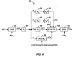
Dabei kann die Anstiegseinheit einen Verzögerungsblock aufweisen, der die gesammelte Prozessvariable um die bestimmte Zeit verzögert, einen Summierer, der ein Differenzsignal ermittelt, das auf eine Differenz zwischen dem aktuellen Prozessvariablenwert und dem von der Verzögerungseinheit verzögerten Prozessvariablenwert hinweist, und eine Teilungseinheit, die das Differenzsignal durch die bestimmte Zeitspanne teilt, um die Prozessvariablen-Anstiegsrate zu erzeugen. Die Anstiegseinheit kann ferner nach einer Veränderung der manipulierten Variable eine Reihe von Prozessvariablen-Anstiegsraten ermitteln, und kann einen statistischen Block aufweisen, der ein statistisches Maß der Reihe von Prozessvariablen-Anstiegsraten ermittelt, um die Prozessvariablen-Anstiegsrate zu erzeugen. Der statistische Block kann beispielsweise ein Maximum der Reihe von Prozessvariablen-Anstiegsraten als Prozessvariablen-Anstiegsrate ermitteln.Herein, the rise unit may include a delay block that delays the collected process variable by the predetermined time, a summer that obtains a difference signal indicative of a difference between the current process variable value and the process variable value delayed by the delay unit, and a dividing unit that receives the difference signal by dividing the determined time period to produce the process variable slew rate. The ramp unit may further determine a set of process variable slew rates upon a change in the manipulated variable, and may include a statistical block that determines a statistical measure of the series of process variable slew rates to produce the process variable slew rate. For example, the statistical block may determine a maximum of the series of process variable slew rates as the process variable slew rate.
Das Prozessmodellierungssystem kann auch eine Abstimmungseinheit aufweisen, die einen oder mehrere Steuerparameter aus dem Prozessmodell ermittelt, die zum Steuern des Prozesses verwendet werden, und es kann eine Steuereinrichtung aufweisen, die den Prozess steuert, derart, dass die Abstimmungseinheit die Steuerparameter vor dem Zeitpunkt, an dem die Steuereinrichtung den Prozess derart steuert, dass er in Reaktion auf die Veränderung der manipulierten Variable einen Dauerzustand erreicht, an die Steuereinrichtung bereitstellt. Das Prozessmodellierungssystem kann auch oder stattdessen eine Simulationseinheit aufweisen, die die Prozessmodellparameter dazu benutzt, den Betrieb des Prozesses vor dem Ende der Prozessreaktionszeit zu simulieren.The process modeling system may also include a voting unit that determines one or more control parameters from the process model that are used to control the process, and may include a controller that controls the process such that the voting unit receives the control parameters prior to the time wherein the controller controls the process to reach a steady state in response to the manipulated variable being changed, to the controller. The process modeling system may also or instead include a simulation unit that uses the process model parameters to simulate the operation of the process before the end of the process response time.
KURZE BESCHREIBUNG DER FIGURENBRIEF DESCRIPTION OF THE FIGURES
Zum gründlicheren Verständnis der Offenbarung sollte auf nachfolgende detaillierte Beschreibung und die begleitenden Figuren Bezug genommen werden, in denen gleiche Bezugszeichen gleiche Elemente bezeichnen. Es zeigen:For a more complete understanding of the disclosure, reference should be made to the ensuing detailed description and the accompanying drawings, in which like numerals denote like elements. Show it:
DETAILLIERTE BESCHREIBUNGDETAILED DESCRIPTION
Bezug nehmend auf
Bei den Arbeitsbereichsvorrichtungen
Die Steuereinrichtung
In einigen Ausführungsformen implementiert die Steuereinrichtung
Wie durch den auseinandergezogenen Block
Ferner können, wie in
Wie in
Der Betrieb der Modellidentifikationsprogramme
ΔMV die Veränderung der manipulierten Variablen ist;
ΔPV1 die Veränderung der Prozessvariable während einer Zeitspanne ΔT1 ist, die unmittelbar vor der Veränderung der Prozessvariablen eintritt, welche durch eine wesentliche Veränderung der manipulierten Variablen eingeleitet wird; und
ΔPV2 die maximale Veränderung der Prozessvariablen während einer Zeitspanne ΔT2 ist, die nach der Veränderung der Prozessvariable eintritt, welche durch eine wesentliche Veränderung der manipulierten Variablen eingeleitet wird. Im Allgemeinen wird diese Berechnung anhand der Veränderungen der Prozessvariablen PV und der manipulierten Variablen durchgeführt, die als prozentuale Veränderungen der Bereiche dieser Variablen ausgedrückt werden.
ΔMV is the change of the manipulated variable;
ΔPV 1 is the change in the process variable during a time ΔT 1 that occurs just prior to the process variable change initiated by a significant change in the manipulated variable; and
ΔPV 2 is the maximum change in the process variable during a period ΔT 2 that occurs after the process variable has been changed, which is caused by a significant change in the manipulated variable is initiated. In general, this calculation is performed on the basis of the changes in the process variable PV and the manipulated variables expressed as percentage changes in the ranges of these variables.
In ähnlicher Weise zeigt
ΔMV die Veränderung der manipulierten Variablen ist; und
ΔPV die Gesamtveränderung der Prozessvariable zwischen dem Anfangswert an einem Zeitpunkt t0 und dem abschließenden Ruhewert der Prozessvariablen ist. Auch diese Berechnung wird typischerweise anhand der Veränderungen der Prozessvariablen ΔPV und der manipulierten Variablen ΔMV durchgeführt, die als prozentuale Veränderungen der Bereiche dieser Variablen ausgedrückt werden. In jedem Fall wird, wie in
ΔMV is the change of the manipulated variable; and
ΔPV is the total change of the process variable between the initial value at a time t 0 and the final idle value of the process variable. Again, this calculation is typically performed based on the changes in the process variable ΔPV and the manipulated variable ΔMV, which are expressed as percentage changes in the ranges of these variables. In any case, as in
In jedem Fall lässt sich ein unkontrollierter Prozess mit einer Prozessverstärkung Kp und einer dominierenden positive Rückkopplungszeitkonstante τp + modellieren. Dabei wird die Prozessverstärkung berechnet als:
Δ%PV eine Veränderung der Prozessvariablen (in Prozent) über einen wesentlichen Zeitraum hinweg ist; und
Δ%CO die Veränderung des Steuereinrichtungsausgangs (d. h. der manipulierten Variablen) in Prozent ist.In any case, an uncontrolled process with a process gain K p and a dominant positive feedback time constant τ p + can be modeled. The process gain is calculated as:
Δ% PV is a change in the process variable (in percent) over a significant period of time; and
Δ% CO is the change in controller output (ie the manipulated variable) in percent.
Außerdem ist die positive Rückkopplungszeitkonstante τp + typischerweise als die Zeit eingestellt, die die Prozessvariable PV benötigt, um das 1,72-fache von Δ%PV zu erreichen. Natürlich werden bei unkontrollierten Prozessen aufgrund der instabilen Natur des Prozesses die meisten charakterisierenden Prüfungen in Steuersituationen mit geschlossener Schleife durchgeführt.In addition, the positive feedback time constant τ p + is typically set as the time required by the process variable PV to reach 1.72 times Δ% PV. Of course, in uncontrolled processes, due to the unstable nature of the process, most characterizing tests are performed in closed loop control situations.
Wie anhand der Graphen aus
Obwohl es sich beim klassischen integrierenden Prozess um einen reinen Chargen- oder flachen Prozess handelt, sind weniger als zehn Prozent der typischen Prozesse der chemischen Industrie integrierende Prozesse. Darüber hinaus handelt es sich bei weniger als einem Prozent der typischen Prozesse der chemischen Industrie um unkontrollierte Prozesse, die nahezu ausschließlich mit hoch exothermen Reaktoren in Zusammenhang stehen, die in Produktionsprozessen für Kunststoff und Spezialchemikalien verwendet werden. Somit sind mehr als 90 Prozent der Prozesse der chemischen Industrie selbstregulierende Prozesse. Aus den oben genannten Gründen verhalten sich jedoch viele kontinuierliche und Chargenzufuhrprozesse der chemischen Industrie (oder wenigstens diejenigen mit den höchsten direkten wirtschaftlichen Vorteilen) wie „nahezu integrierende” Prozesse und können für die hierin beschriebenen Modellierungszwecke als solche behandelt werden. Insbesondere ist ein „nahezu integrierender” Prozess im hier verwendeten Sinne ein Prozess, der zunächst über wenigstens zwei Stillstandszeiten nach Ablauf der Prozessstillstandszeitspanne wie ein integrierender Prozess reagiert, indem die Prozessvariable dazu neigt, kurz nach dem Ablauf der Prozessstillstandszeitspanne in Reaktion auf eine Stufenänderung der manipulierten Variablen mit einer relativ konstanten Rate anzusteigen.Although the classical integrating process is a pure batch or flat process, less than ten percent of typical processes in the chemical industry are integrating processes. Moreover, less than one percent of the typical processes in the chemical industry are uncontrolled processes that are almost exclusively associated with highly exothermic reactors used in plastic and specialty chemicals production processes. Thus, more than 90 percent of the processes in the chemical industry are self-regulating processes. However, for the reasons given above, many continuous and batch feed processes of the chemical industry (or at least those with the highest direct economic benefits) behave as "nearly integrating" processes and can be treated as such for the modeling purposes described herein. In particular, a "near integrating" process as used herein is a process that initially responds as an integrating process for at least two downtime periods after the process downtime period has elapsed, with the process variable tending to close shortly after the end of the process downtime period in response to a stage change of the manipulated one To increase variables at a relatively constant rate.
Aufgrund der Tatsache, dass die meisten interessierenden Prozesse der Prozesssteuerungsindustrie integrierende Prozesse sind oder sich als nahezu integrierende Prozesse charakterisieren lassen, ist ein Verfahren zum schnellen Identifizieren eines Prozessmodells für einen Prozess, das unten beschrieben wird, dazu in der Lage, mit allen diesen Prozesstypen zu arbeiten. Allgemein ausgedrückt ermittelt das Verfahren zum schnellen Identifizieren eines Prozessmodells für einen Prozess, das hierin beschrieben wird, anhand der Reaktion der Prozessvariablen auf eine Veränderung der manipulierten Variablen in der kurzen Zeitspanne nach der Veränderung der manipulierten Variablen eine Prozessstillstandszeit θp und eine integrierende Verstärkung Ki für den Prozess. Wie oben angegeben, lässt sich dieses Verfahren auf viele verschiedene Typen von Prozessen oder Prozessschleifen anwenden, darunter integrierende Prozessschleifen und selbstregulierende oder unkontrollierte Prozessschleifen, die sich als „nahezu integrierende” Prozessschleifen charakterisieren lassen.Due to the fact that most of the processes of interest to the process control industry are integrating processes or can be characterized as nearly integrating processes, a method for quickly identifying a process model for a process described below is capable of all of these types of processes work. Generally speaking, the method for quickly identifying a process model for a process described herein determines a process stoppage time θ p and an integrating gain K i from the response of the process variable to a change in the manipulated variable in the short time after the manipulated variable has changed for the process. As indicated above, this method can be applied to many different types of processes or process loops, including integrating process loops and self-regulating or uncontrolled process loops that can be characterized as "nearly integrating" process loops.
Insbesondere lässt sich für einen Prozess ein relativ genaues Prozessmodell entwickeln, indem anhand der Reaktion der Prozessvariable während einer kurzen Zeitspanne unmittelbar nach der Veränderung der manipulierten Variablen oder kurz nach dem Ablauf der Stillstandszeitspanne eine integrierende Verstärkung des Prozesses geschätzt oder ermittelt wird. Bei integrierenden oder nahezu integrierenden Prozessen neigt die Prozessvariable nach Ablauf der Stillstandszeitspanne des Prozesses sogar dazu, sich sehr schnell mit einer Anstiegsrate zu verändern, die über die gesamte Prozessreaktionszeit hinweg relativ konstant bleibt, insbesondere bei der Offenschleifensteuerung. Diese Anstiegsrate der Prozessvariablen kann auf diese Weise an einem relativ frühen Punkt in der Prozessreaktionszeit gemessen werden, und diese gemessene Anstiegsrate kann dann dazu benutzt werden, eine integrierende Verstärkung für den Prozess zu ermitteln, die wiederum dazu benutzt werden kann, Parameter des Prozesses (Prozessmodellparameter) zu schätzen oder zu charakterisieren, beispielsweise die Prozessverstärkung und die dominierende Zeitkonstante, ohne dass gewartet werden muss, bis die gesamte Reaktionsdauer des Prozesses stattgefunden hat oder bis der Prozess derart gesteuert wurde, dass er einen Dauerzustand in Reaktion auf die Veränderung einer manipulierten Variablen zu erreicht. Auf diese Weise lässt sich auch für langsam reagierende Prozesse wie z. B. Prozesse, die Minuten, Stunden oder sogar Tage benötigen, um ihren abschließenden Ruhepunkt zu erreichen, anhand der Reaktion der Prozessvariablen während einer relativ kurzen Zeitspanne unmittelbar nach der Veränderung der Steuerungs- oder der manipulierten Variablen rasch ein Prozessmodell ermitteln oder identifizieren.In particular, a relatively accurate process model can be developed for a process by estimating or determining an integrating enhancement of the process based on the response of the process variable during a short period of time immediately after the manipulated variable has changed or shortly after the end of the downtime period. In the case of integrating or nearly integrating processes, the process variable even after the end of the standstill period of the process even tends to change very rapidly at a rate of increase which remains relatively constant over the entire process reaction time, in particular in open-loop control. This rate of increase of the process variable can thus be measured at a relatively early point in the process response time, and this measured rate of increase can then be used to determine an integrating gain for the process, which in turn can be used to set parameters of the process (process model parameters ), such as the process gain and the dominant time constant, without having to wait until the entire reaction time of the process has taken place or until the process has been controlled to allow a steady state in response to the manipulated variable change reached. In this way, even for slow-reacting processes such. For example, processes that take minutes, hours, or even days to reach their final resting point can quickly identify or identify a process model based on the response of the process variable over a relatively short period of time, immediately after the control or manipulated variable changes.
Natürlich beinhaltet das Ermitteln der Prozessstillstandszeit das Ermitteln des Zeitpunkts, an dem eine Veränderung einer manipulierten Variablen, z. B. eine Sollwertveränderung oder ein Ausgang der Steuereinrichtung, in den Prozess eingebracht wird, und das Messen der gesteuerten Prozessvariablen (oder anderer interessierender Prozessvariablen), um zu identifizieren, wann die Prozessvariable sich in Reaktion auf die Veränderung der manipulierten Variablen zu verändern beginnt. Die Prozessstillstandszeit wird dann als die Zeit zwischen dem Ausgang der Steuerungseinrichtung (der manipulierten Variablen) und dem Beginn der Veränderung der Prozessvariablen bestimmt. Natürlich existieren viele bekannte Möglichkeiten zum Schätzen der Prozessstillstandszeit, und es kann jedes beliebige dieser Verfahren verwendet werden, um die Prozessstillstandszeit in einem Prozess zu ermitteln. Of course, determining the process down time involves determining the time at which a change in a manipulated variable, e.g. A setpoint change or an output of the controller is introduced into the process, and measuring the controlled process variables (or other process variables of interest) to identify when the process variable begins to change in response to the manipulated variable change. The process down time is then determined as the time between the output of the controller (the manipulated variable) and the beginning of the process variable change. Of course, there are many known ways to estimate process down time, and any of these methods can be used to determine process down time in a process.
Um die integrierende Verstärkung Ki des Prozesses zu ermitteln oder zu schätzen, identifiziert oder misst das Verfahren die Anstiegsrate der Prozessvariablen über eine kurze Zeit nach dem Ablauf der Stillstandszeitspanne θp und benutzt die identifizierte Anstiegsrate dazu, ein Verhältnis einer Veränderung der Prozessvariablen im Zeitverlauf zu einer Veränderung der manipulierten Variablen zu ermitteln. Die kurze Zeit nach dem Ablauf der Stillstandszeitspanne θp, während der die Anstiegsrate der Prozessvariablen ermittelt wird, kann allgemein zwischen dem anfänglichen Abschnitt der Prozessreaktionszeit nach dem Ende der Stillstandszeitspanne, z. B. vor dem Ablauf der Hälfte der Prozessreaktionszeit, innerhalb einer oder einiger Stillstandszeiten nach dem Ende der Stillstandszeit, innerhalb von zehn Stillstandszeiten nach dem Ende der Stillstandszeitspanne usw. liegen. Beispielsweise kann das Verfahren die Anstiegsrate der Prozessvariablen innerhalb einer Zeitspanne ermitteln, die sich über zwei bis sechs Vielfache der identifizierten Prozessstillstandszeit nach dem Ablauf der Prozessstillstandszeitspanne erstreckt. Allerdings kann die Anstiegsrate der Prozessvariablen auch über jede andere gewünschte Zeitspanne unmittelbar oder kurz nach dem Ablauf der Stillstandszeitspanne ermittelt werden, beispielsweise über eine Zeitspanne, die zwei oder mehr Vielfachen der identifizierten Stillstandszeit entspricht. In einer Ausführungsform kann die Anstiegsrate der Prozessvariablen mehrfach über eine Anzahl aufeinanderfolgender (z. B. sechs bis zehn) Zeitspannen nach dem Ablauf der Stillstandszeitspanne ermittelt werden, wobei die Länge jeder Zeitspanne beispielsweise der identifizierten Prozessstillstandszeit entspricht. In diesem Fall kann das Verfahren dann die höchste oder steilste (d. h. maximale) gemessene Anstiegsrate als die identifizierte Anstiegsrate der Prozessvariablen wählen. In anderen Ausführungsformen kann die ausgewählte oder identifizierte Prozessvariable ein durchschnittliches, Median- oder anderes statistisches Maß einer Mehrzahl gemessener Anstiegsraten sein, die für unterschiedliche Zeitpunkte während der Prozessvariablenreaktion unmittelbar oder kurz nach dem Ablauf der Prozessstillstandszeitspanne ermittelt wurden. Außerdem kann eine einzelne Anstiegsrate der Prozessvariablen anhand von Daten gemessen oder ermittelt werden, die sich über eine gewünschte Zeitspanne nach dem Ablauf der Stillstandszeitspanne erstrecken, beispielsweise eine Zeitspanne von zwei, drei oder mehr Stillstandszeiten.To determine or estimate the integrating gain K i of the process, the method identifies or measures the rate of increase of the process variable over a short time after the expiration of the standstill period θ p, and uses the identified slew rate to estimate a ratio of process variable change over time a change in the manipulated variables. The short time after the expiration of the standstill period θ p during which the rate of increase of the process variable is determined may generally be between the initial portion of the process response time after the end of the downtime period, e.g. B. before the expiry of half of the process reaction time, within one or some downtime after the end of the downtime, within ten downtime after the end of the downtime period, etc. lie. For example, the method may determine the rate of increase of the process variable within a period of time that is two to six times greater than the identified process down time after the expiration of the process downtime period. However, the rate of increase of the process variable may also be determined over any other desired time period immediately or shortly after the expiration of the downtime period, for example, over a period equal to two or more multiples of the identified downtime. In one embodiment, the rate of increase of the process variable may be determined multiple times over a number of consecutive (e.g., six to ten) time periods after the expiration of the downtime period, wherein the length of each period corresponds, for example, to the identified process downtime. In this case, the method may then choose the highest or steepest (ie, maximum) measured slew rate as the identified slew rate of the process variable. In other embodiments, the selected or identified process variable may be an average, median or other statistical measure of a plurality of measured slew rates determined for different times during the process variable response immediately or shortly after the end of the process downtime period. In addition, a single slew rate of the process variable may be measured or determined from data that extends over a desired amount of time after the expiration of the downtime period, such as a period of two, three, or more down times.
Nach der Ermittlung werden die Anstiegsraten der Prozessvariablen dazu benutzt, die integrierende Verstärkung Ki des Prozesses zu bestimmen. Insbesondere kann die integrierende Verstärkung Ki des Prozesses als das Verhältnis der prozentualen Veränderung der Anstiegsrate der Prozessvariablen im Zeitverlauf (d. h. der Anstiegsrate der Prozessvariablen ausgedrückt als prozentuale Veränderung der Prozessvariable im Zeitverlauf) zu der Veränderung der manipulierten Variablen (ausgedrückt als prozentuale Veränderung der manipulierten Variablen) ermittelt werden. Dieses Verhältnis lässt sich mathematisch ausdrücken als:
ΔT1 und ΔT2 Zeitintervalle zum Ermitteln der Anstiegszeit sind;
ΔPV1 und ΔPV2 die maximalen Veränderungen der gemessenen Prozessvariablen (in Prozent des Bereichs der Prozessvariablen) während der Zeitintervalle ΔT1 bzw. ΔT2, sind; und
ΔMV die Veränderung der manipulierten Variablen in Prozent des Bereichs der manipulierten Variable ist.After the determination, the slew rates of the process variables are used to determine the integrating gain K i of the process. In particular, the integral gain K i of the process may be expressed as the ratio of the percent change in the process variable slew rate over time (ie, the rate of increase of the process variable expressed as a percentage change in the process variable over time) to the manipulated variable change (expressed as a percentage change in the manipulated variable ) be determined. This ratio can be expressed mathematically as:
ΔT 1 and ΔT 2 are time intervals for determining the rise time;
ΔPV 1 and ΔPV 2 are the maximum changes of the measured process variables (as a percentage of the range of process variables) during the time intervals ΔT 1 and ΔT 2 , respectively; and
ΔMV is the change in the manipulated variable as a percentage of the manipulated variable's range.
Dabei kann es sich bei ΔT1 um ein beliebiges Zeitintervall vor dem Ende der Stillstandszeitspanne θp handeln, und bei ΔT2 um ein beliebiges Zeitintervall nach dem Ende der Stillstandszeitspanne θp, das jedoch vorzugsweise unmittelbar oder kurz nach dem Ablauf der dem Ende der Stillstandszeitspanne θp liegt. Außerdem können ΔT1 und ΔT2 im Vergleich zur Prozessreaktionszeit relativ kurze Zeitspannen sein, beispielsweise eine bis sechs Stillstandszeiten.In this case, ΔT 1 may be any time interval before the end of the standstill period θ p , and ΔT 2 at any time interval after the end of the standstill period θ p , but preferably immediately or shortly after the end of the downtime period θ p is. Additionally, ΔT 1 and ΔT 2 may be relatively short periods of time compared to the process response time, for example, one to six downtime periods.
Anschließend können die identifizierte Prozessstillstandszeit θp und die integrierende Verstärkung Ki dazu benutzt werden, einen oder mehrere Prozessmodellparameter wie z. B. eine Prozessverstärkung, eine Prozessstillstandszeit und eine dominierende Zeitkonstante des Prozesses zu ermitteln, oder sie können dazu benutzt werden, Faktoren, Größen oder Variablen eines Erste-Prinzipien-Modells wie z. B. eines Gewöhnliche-Differenzialgleichung-(ordinary differential equation, ODE)-Prozessmodells zu ermitteln.Subsequently, the identified process down time θ p and the integrating gain K i can be used to determine one or more process model parameters, such as the one or more process parameters. For example, you may or may not want to determine a process gain, a process downtime, and a dominant time constant of the process factors, quantities or variables of a first-principles model such as B. an ordinary differential equation (ODE) process model to determine.
Da die geschätzte Prozessstillstandszeit θp und die geschätzte integrierende Verstärkung Ki sich innerhalb einer relativ kurze Zeitspanne nach der Veränderung der manipulierten Variablen (oder Störvariablen), z. B. innerhalb von zwei bis zehn Stillstandszeiten nach der Veränderung der manipulierten Variablen ermitteln lassen, wird man verstehen, dass ein Prozessmodell für den Prozess sehr schnell ermittelt werden kann, und dass es sogar in vielen Fällen ermittelt werden kann, bevor die Steuereinrichtung die Steuerung der Prozessvariablen zum Erreichen eines Dauerzustands in Reaktion auf die Veränderung der manipulierten Variablen abgeschlossen hat.Since the estimated process stoppage time θ p and the estimated integrating gain K i are within a relatively short time after the manipulated variable (s) change, e.g. B. within two to ten downtime after the manipulated variables are changed, it will be understood that a process model for the process can be determined very quickly, and that it can even be determined in many cases before the controller controls the control of the process Process variable to achieve a steady state in response to the change of manipulated variables has completed.
Somit beinhaltet die verallgemeinerte Verfahrensweise zum schnellen Identifizieren eines Prozessmodells das Identifizieren der Prozessstillstandszeit als die Zeit, vor der eine merkliche Reaktion der Prozessvariablen vorliegt, und das Identifizieren der integrierenden Prozessverstärkung anhand einer Veränderung der Anstiegsraten vor und nach der Stillstandszeit. Die Zeitspanne zum Identifizieren der Veränderung der Anstiegsrate kann lediglich zwei Stillstandszeiten betragen und kann sich auf eine beliebige Anzahl von Stillstandszeiten erstrecken, ist jedoch stets weniger als die Gesamtprozessreaktionszeit. Die Berechnung kann fortfahren, die Ermittlung der integrierenden Verstärkung zu verfeinern, bis die Anstiegsrate abnimmt oder beginnt, abzunehmen. Man wird verstehen, dass die Berechnung der Stillstandszeit und der integrierenden Verstärkung allgemein nach einer Veränderung des Schleifensollwerts oder nach dem abschließenden Steuerelement beginnt, das eine quantifizierbare Veränderung einer Störvariablen, manipulierten Variablen oder eines Prozesseingangs auslöst, die bzw. der eine messbare Prozessvariable beeinflusst. Diese Prozessausgänge können beispielsweise PID-Prozessvariablen, MPC-gesteuerte Variablen oder beliebige prozessbezogene, wirtschaftliche oder qualitätsbezogene Variablen sein. Die integrierende Verstärkung Ki kann dann dazu benutzt werden, experimentelle und/oder hybride experimentelle ODE-Modelle oder andere Modelle für Anlagensimulationen bereitzustellen.Thus, the generalized procedure for quickly identifying a process model includes identifying the process down time as the time that a significant reaction of the process variable occurs, and identifying the integrating process gain based on a change in the rise rates before and after the downtime. The period of time for identifying the change in the rate of increase may be only two down times and may extend to any number of down times, but is always less than the total process response time. The calculation may continue to refine the integration gain determination until the rate of increase decreases or begins to decrease. It will be appreciated that the computation of down time and integral gain generally begins after a change in the loop setpoint or after the final control that triggers a quantifiable change in a disturb variable, manipulated variable, or process input that affects a measurable process variable. These process outputs may be, for example, PID process variables, MPC controlled variables or any process, economic or quality related variables. The integrating gain K i can then be used to provide experimental and / or hybrid experimental ODE models or other models for plant simulations.
Ferner wird geschätzt, dass sich die Zeit zum automatischen Identifizieren und Einsetzen von Prozessmodellen mithilfe dieses Verfahrens auf einige Minuten reduzieren lässt, was die Entwicklung einer anlagenweiten Simulation innerhalb einer sehr kurzen Zeitspanne ermöglicht. Die integrierende Verstärkung Ki kann auch dazu benutzt werden, ODE-Modelle anhand von Material- und Energiebilanzen zu parametrisieren, indem die integrierende Verstärkung Ki für selbstregulierende und nicht selbstregulierende Prozesse mit positiver Rückkopplung direkt zum Integrieren oder Berechnen der Prozesszeitkonstante als dem Verhältnis einer Prozessverstärkung zu einer nahezu integrierenden Verstärkung benutzt werden.It is also estimated that the process of automatically identifying and deploying process models using this method can be reduced to a few minutes, allowing the development of plant-wide simulation in a very short time span. The integrating gain K i can also be used to parameterize ODE models based on material and energy balances by using the integrating gain K i for self-regulating and non-self-regulating positive feedback processes directly for integrating or calculating the process time constant as the ratio of process gain be used to a nearly integrating amplification.
Insbesondere kann eine Prozessverstärkung Kp sowohl für selbstregulierende als auch unkontrollierte Prozesse wie folgt berechnet oder annähernd berechnet werden:
Außerdem können eine Prozesszeitkonstante mit negativer Rückkopplung τp – für einen selbstregulierenden oder eine Prozesszeitkonstante mit positiver Rückkopplung τp + für einen unkontrollierten Prozess wie folgt berechnet werden:
In diesem Fall also wird die Prozessverstärkung Kp als das Verhältnis der anfänglichen Prozessvariable zur anfänglichen manipulierten Variablen unmittelbar vor der Veränderung der manipulierten Variablen berechnet. Es ist wichtig, dass die experimentellen und hybriden Modelle Abweichungen der manipulierten Variablen als Eingänge benutzen und als Ausgänge Abweichungen der Prozessvariablen bereitstellen, um mit Betriebspunkt-Nichtlinearitäten umzugehen, die in der Prozessindustrie vorherrschend sind.In this case, the process gain K p is calculated as the ratio of the initial process variable to the initial manipulated variable immediately before the manipulated variable is changed. It is important that the experimental and hybrid models use deviations of the manipulated variables as inputs and provide as outputs deviations of the process variables to deal with operating point nonlinearities that are prevalent in the process industry.
Wie in
Ein Ausgang des Blocks
Die Anstiegsrate der Prozessvariablen wird dann an einen Maximalwertdetektionskreis oder -block
In jedem Fall arbeiten die hier beschriebenen Blöcke
Wie anhand von
Während der Block
Indem die identifizierte Stillstandszeit in einem Verzögerungsblock sowohl während der Prozessstillstandszeit als auch nach der Prozessstillstandszeit zum Berechnen der maximalen Veränderung der Prozessvariablen, die auf einer Veränderung der manipulierten Variablen beruht, benutzt wird, wird es zudem möglich, das hier beschriebene schnelle Modellierungsverfahren auf Prozesse anzuwenden, deren Stillstandszeit größer als die Prozesszeitkonstante ist, d. h. auf stillstandszeitdominierten Prozesse. Es kann gezeigt werden, dass die resultierende universelle Gleichung für die Steuereinrichtungsverstärkung zu der folgenden Steuereinrichtungsverstärkung für einen stillstandszeitdominierten Prozess führt: ![]()
![]()
Hierbei:
- Ki
- = Integrierende Verstärkung;
- ΔPVmax
- = Maximale beobachtete Veränderung der Prozessvariablen;
- ΔCOmax
- = Veränderung des Ausgangs der Steuereinrichtung (z. B. die manipulierte Variable); und
- Δt
- = Veränderung im Zeitverlauf, über den ΔPVmax gemessen wird.
- K i
- = Integrating reinforcement;
- ΔPV max
- = Maximum observed change of the process variable;
- ΔCO max
- = Change in the output of the controller (eg the manipulated variable); and
- .delta.t
- = Change over time over which ΔPV max is measured.
Es ist außerdem bekannt, dass die Steuereinrichtungsverstärkung einer PID-Steuereinrichtung wie folgt berechnet werden kann: 
Das Einsetzen von Gleichung (1) in Gleichung (2) ergibt: ![]()
![]()
Wenn das Zeitintervall gleich der beobachteten Prozessstillstandszeit (Δt = θo) ist und ΔPVmax und ΔCOmax erzeugt werden, indem die Prozessvariable und der Ausgang der Steuereinrichtung durch einen Stillstandszeitblock geleitet werden, wobei der Stillstandszeitparameter auf den Wert der beobachteten Prozessstillstandszeit θo eingestellt ist, so ist die integrierende Prozessverstärkung Ki einfach ![]()
![]()
Der Abstimmungsfaktor Kx für die maximale Störunterdrückung kann beispielsweise für selbstregulierende Prozesse auf 0,4, für integrierende Prozesse auf 0,5 und für unkontrollierte Prozesse auf 0,6 eingestellt sein, was einem Lambda gleich der beobachteten Prozessstillstandszeit entspricht (λ = θo). In Situationen, in denen das Aktualisierungsintervall wesentlich größer als die Prozesszeit bis zum Dauerzustand ist, kann der Faktor Kx auf 1,0 eingestellt werden. Natürlich kann der Faktor Kx auch auf andere Weise berechnet werden.For example, the tuning factor K x for the maximum interference suppression can be set to 0.4 for self-regulating processes, 0.5 for integrating processes, and 0.6 for uncontrolled processes, which corresponds to a lambda equal to the observed process standstill time (λ = θ o ). , In situations where the update interval is significantly greater than the process time to steady state, the factor K x can be set to 1.0. Of course, the factor K x can also be calculated in other ways.
In einem Fall kann die Überprüfung auf die maximale Veränderung der Prozessvariablen eine Prozessstillstandszeit, nachdem die Veränderung des Ausgangs der Steuereinrichtung (der manipulierten Variablen) über einen Auslösepegel gestiegen ist, beginnen, und könnte beispielsweise über vier oder mehr Stillstandszeitintervalle andauern. Die Prozessstillstandszeit ist als das Zeitintervall vom Beginn einer Veränderung des Ausgangs der Steuereinrichtung (der manipulierten Variablen) bis zu einer beobachteten Veränderung der Prozessvariablen über das Rauschband hinaus identifiziert. Das Rauschband kann voreingestellt sein oder automatisch identifiziert werden. Die Prüfung eignet sich für eine Veränderung des Ausgangs der Steuereinrichtung im Handbuch oder für eine Sollwertänderung, wenn die Steuereinrichtungsverstärkung hoch ist.In one instance, the process variable maximum variance check may begin a process down time after the change in the output of the controller (manipulated variable) has risen above a trigger level and may, for example, continue for four or more standstill time intervals. The process down time is identified as the time interval from the beginning of a change in the output of the controller (the manipulated variable) to an observed change in the process variable beyond the noise band. The noise band can be preset or automatically identified. The test is suitable for changing the output of the controller in the manual or for a set point change if the controller gain is high.
Um für eine schnelle Aktualisierung und eine minimale Reaktion auf Rauschen zu sorgen, ist es wünschenswert, dass die in diesem Verfahren benutzten Stillstandszeitblöcke dazu benutzt werden, eine kontinuierliche oder nahezu kontinuierliche Reihe von verzögerten Prozessvariablen und verzögerten Steuereinrichtungsausgangsvariablen erzeugen, um die Veränderung dieser Variablen über das Stillstandszeitintervall hinweg zu berechnen. In diesem Fall kann der Verzögerungsblock eine Folge von verzögerten Prozessvariablenwerten erzeugen, die zeitlich um weniger als die beobachtete Stillstandszeit getrennt sind (z. B. 10 oder 100 Messungen pro Stillstandszeitspanne), und der Summierer kann eine Differenz der Prozessvariable für jeden verzögerten Prozessvariablenwert (und den dann aktuellen Wert des verzögerten Prozessvariablenwerts) ermitteln, um dadurch eine Folge von Prozessvariablen-Differenzwerten zu erzeugen. Auf diese Weise wird der Prozessvariablenanstiegswert viele Male während einer bestimmten Zeitspanne gemessen, deren Länge gleich der Stillstandszeitspanne ist. Man wird verstehen, dass sich das Verfahren auf diese Weise auf das schnelle Ermitteln von Prozessmodellen für stillstandszeitdominierte Schleifen anwendbar ist und dafür benutzen lässt, wobei die Steuereinrichtungsverstärkung schlicht der faktorisierte Kehrwert der Offenschleifenprozessverstärkung ist.In order to provide a fast update and a minimal response to noise, it is desirable that the idle time blocks used in this method be used to generate a continuous or near continuous series of delayed process variables and delayed controller output variables to control the change of these variables over the To calculate standstill time interval. In this case, the delay block may generate a sequence of delayed process variable values that are time-separated by less than the observed downtime (eg, 10 or 100 measurements per downtime period), and the summer may calculate a process variable difference for each delayed process variable value (and determine the then current value of the delayed process variable value) to thereby generate a sequence of process variable difference values. In this way, the process variable rise value is measured many times during a certain period of time equal in length to the standstill period. It will be appreciated that in this manner the method is applicable to and can be used for quickly determining process models for deadband dominated loops, where the controller gain is simply the factored inverse of the open loop process gain.
In jedem Fall kann die PID-Steuereinrichtungsverstärkung Kc für eine stillstandszeitdominierte Schleife wie folgt berechnet werden: ![]()
![]()
Insbesondere führt das Simulationssystem
Im ersten Modellzweig implementiert ein Block
Bei einem zweiten Modellierungszweig, der typischerweise einem integrierenden Prozess zugeordnet ist oder zu dessen Simulation benutzt wird, wird die verzögerte Veränderung der manipulierten Variablen ΔMV an einen Integratorblock
In einem dritten Modellierungsstrom, der typischerweise einem selbstregulierenden Prozess zugeordnet ist, wird die verzögerte Veränderung der manipulierten Variablen ΔMV an einen Multiplikations- oder Verstärkungsblock
In einem vierten Modellierungsstrom, der typischerweise einem unkontrollierten Prozess zugeordnet ist, wird die verzögerte Veränderung der manipulierten Variablen ΔMV an einen Multiplikations- oder Verstärkungsblock
Wie in
Auf jeden Fall können alle vier Modellierungsströme eine Schätzung der Reaktion der Prozessvariablen PV zu einem jeweils unterschiedlichen Satz von Zeitpunkten oder in kontinuierlicher Weise im Verlauf eines Zeithorizonts erzeugen, um auf diese Weise eine Schätzung der Gesamtreaktion der Prozessvariablen PV auf eine Veränderung der manipulierten Variablen MV zu erzeugen. Auf diese Weise lässt sich die Gesamtreaktion der Prozessvariablen PV im Verlauf eines Steuerhorizonts schätzen oder simulieren, um die Reaktion der Prozessvariablen PV auf die Veränderung der manipulierten Variablen MV zu simulieren oder zu schätzen. Dieses Merkmal erlaubt es einem Benutzer, die Steuerreaktion oder die Steuermaßnahme zu verändern oder zu ändern, um für eine bessere oder wünschenswertere Steuerreaktion zu sorgen. Beispielsweise kann der Benutzer die Simulation dazu benutzen, neue Steuerparameter zu erzeugen, z. B. Steuereinrichtungsabstimmungsparameter, um die Steuereinrichtung anhand der Prozessmodellsimulation neu abzustimmen und eine bessere Steuerreaktion zu bewirken. Da die Prozessmodelle, die im Simulationssystem
Natürlich ist das Simulationssystem
Bei Bedarf kann ein Benutzer zudem aufgrund von Faktoren wie z. B. dem Typ des gesteuerten Prozesses, die dem Benutzer bekannt sein können, auswählen oder bestimmen, welcher der Modellierungszweige in einer bestimmten Simulation benutzt werden soll (d. h. wie der Schalter
Obwohl das schnelle Prozessmodellidentifikations- und -erzeugungssystem
Jede der oben beschriebenen Anwendungen oder Blöcke kann als Programme, Module oder andere Komponenten einer oder mehrerer integrierter Anwendungen implementiert sein. Die offenbarte Anordnung der Anwendungsfunktionalität dient nur der vereinfachten Darstellung und sagt nichts über die breite Spanne an Verfahrensweisen aus, in denen die Funktionalität auf einem Computer implementiert oder an einen Bediener oder anderen Benutzer bereitgestellt werden kann. Bei der Implementierung können alle hierin beschriebenen Softwaremodule oder Programme auf jedem beliebigen computerlesbaren Speicher gespeichert sein, z. B. auf einer Magnetplatte, einer Laser-Disk oder einem anderen Speichermedium, in einem RAM oder ROM eines Computers oder Prozessors usw. Ebenso kann diese Software unter Verwendung jedes beliebigen bekannten oder gewünschten Verfahrens an einen Benutzer, eine Prozessanlage oder einen Bedienerarbeitsplatzrechner ausgeliefert werden, beispielsweise auf einer computerlesbaren Disk oder einem anderen transportierbaren Computerspeichermechanismus oder über einen Kommunikationskanal wie eine Telefonleitung, das Internet, das World Wide Web oder jedes andere lokale Netz oder Fernnetz usw. Ferner kann die Software direkt ohne Modulation oder Verschlüsselung bereitgestellt werden, oder sie kann unter Verwendung jeder beliebigen geeigneten Modulationsträgerwelle und/oder jedes beliebigen geeigneten Verschlüsselungsverfahrens moduliert und/oder verschlüsselt werden, bevor sie über einen Kommunikationskanal übertragen wird.Each of the applications or blocks described above may be implemented as programs, modules, or other components of one or more integrated applications. The disclosed arrangement of application functionality is for convenience only and does not say anything about the wide range of procedures in which the functionality may be implemented on a computer or provided to an operator or other user. In implementation, all of the software modules or programs described herein may be stored on any computer-readable memory, e.g. On a magnetic disk, a laser disk or other storage medium, in a RAM or ROM of a computer or processor, etc. Similarly, this software may be delivered to a user, process plant, or operator workstation using any known or desired method. For example, on a computer-readable disk or other portable computer storage mechanism, or over a communications channel such as a telephone line, the Internet, the World Wide Web, or any other local area network, etc. Furthermore, the software may be provided directly without modulation or encryption, or may be provided under Using any suitable modulation carrier wave and / or any suitable encryption method, and / or encrypted before being transmitted over a communication channel.
Obwohl also die vorliegende Erfindung unter Bezugnahme auf spezifische Beispiele beschrieben wurden, die nur der Veranschaulichung dienen und die Erfindung nicht einschränken sollen, wird es für Durchschnittsfachleute auf der Hand liegen, dass Änderungen, Hinzufügungen oder Weglassungen an den offenbarten Ausführungsformen vorgenommen werden können, ohne vom Geist und Umfang der Erfindung abzuweichen.Thus, while the present invention has been described with reference to specific examples, which are given by way of illustration only and are not intended to limit the invention, it will be apparent to those of ordinary skill in the art that changes, additions or omissions to the disclosed embodiments can be made without departing from Deviating spirit and scope of the invention.
ZITATE ENTHALTEN IN DER BESCHREIBUNG QUOTES INCLUDE IN THE DESCRIPTION
Diese Liste der vom Anmelder aufgeführten Dokumente wurde automatisiert erzeugt und ist ausschließlich zur besseren Information des Lesers aufgenommen. Die Liste ist nicht Bestandteil der deutschen Patent- bzw. Gebrauchsmusteranmeldung. Das DPMA übernimmt keinerlei Haftung für etwaige Fehler oder Auslassungen.This list of the documents listed by the applicant has been generated automatically and is included solely for the better information of the reader. The list is not part of the German patent or utility model application. The DPMA assumes no liability for any errors or omissions.
Zitierte PatentliteraturCited patent literature
- US 7113834 [0008] US 7113834 [0008]
- US 6577908 [0008] US 6577908 [0008]
Claims (49)
Applications Claiming Priority (4)
| Application Number | Priority Date | Filing Date | Title |
|---|---|---|---|
| US30973710P | 2010-03-02 | 2010-03-02 | |
| US61/309,737 | 2010-03-02 | ||
| US12/960,432 US8756039B2 (en) | 2010-03-02 | 2010-12-03 | Rapid process model identification and generation |
| US12/960,432 | 2010-12-03 |
Publications (1)
| Publication Number | Publication Date |
|---|---|
| DE102011012710A1 true DE102011012710A1 (en) | 2011-09-08 |
Family
ID=43881499
Family Applications (1)
| Application Number | Title | Priority Date | Filing Date |
|---|---|---|---|
| DE102011012710A Pending DE102011012710A1 (en) | 2010-03-02 | 2011-03-01 | Fast identification and generation of process models |
Country Status (5)
| Country | Link |
|---|---|
| US (1) | US8756039B2 (en) |
| JP (2) | JP5830251B2 (en) |
| CN (2) | CN106094527B (en) |
| DE (1) | DE102011012710A1 (en) |
| GB (2) | GB2478402B (en) |
Cited By (1)
| Publication number | Priority date | Publication date | Assignee | Title |
|---|---|---|---|---|
| WO2022073674A1 (en) * | 2020-10-08 | 2022-04-14 | Krones Ag | Method for operating a machine in a processing plant for containers and machine for handling containers |
Families Citing this family (13)
| Publication number | Priority date | Publication date | Assignee | Title |
|---|---|---|---|---|
| US9335042B2 (en) | 2010-08-16 | 2016-05-10 | Emerson Process Management Power & Water Solutions, Inc. | Steam temperature control using dynamic matrix control |
| US9217565B2 (en) | 2010-08-16 | 2015-12-22 | Emerson Process Management Power & Water Solutions, Inc. | Dynamic matrix control of steam temperature with prevention of saturated steam entry into superheater |
| US9447963B2 (en) | 2010-08-16 | 2016-09-20 | Emerson Process Management Power & Water Solutions, Inc. | Dynamic tuning of dynamic matrix control of steam temperature |
| US9163828B2 (en) | 2011-10-31 | 2015-10-20 | Emerson Process Management Power & Water Solutions, Inc. | Model-based load demand control |
| US9311434B1 (en) * | 2012-03-26 | 2016-04-12 | The Mathworks, Inc. | Ladder logic modeling and simulation |
| JP6216112B2 (en) * | 2012-11-30 | 2017-10-18 | アズビル株式会社 | Multivariable control apparatus and method |
| JP6157219B2 (en) * | 2013-05-29 | 2017-07-05 | アズビル株式会社 | Control apparatus and control method |
| JP6181023B2 (en) * | 2013-12-20 | 2017-08-16 | 株式会社神戸製鋼所 | Thickness control method of rolling mill |
| JP6647931B2 (en) * | 2016-03-16 | 2020-02-14 | 株式会社Kelk | Semiconductor wafer temperature control device and semiconductor wafer temperature control method |
| US10969749B2 (en) | 2017-08-22 | 2021-04-06 | Honeywell Limited | Application of model predictive control (MPC)-based forced ramping of process input variables and process output reference trajectory design over a prediction horizon for MPC-based paper machine grade change control |
| US11472115B2 (en) | 2019-03-21 | 2022-10-18 | General Electric Company | In-situ monitoring system assisted material and parameter development for additive manufacturing |
| CN111413863B (en) * | 2020-03-27 | 2023-04-07 | 南京理工大学 | Particle swarm fuzzy Smith temperature control method based on 3D printing nozzle |
| KR20230043971A (en) * | 2020-07-27 | 2023-03-31 | 와틀로 일렉트릭 매뉴팩츄어링 컴파니 | Systems and methods for using intermediate data to improve system control and diagnostics |
Citations (2)
| Publication number | Priority date | Publication date | Assignee | Title |
|---|---|---|---|---|
| US6577908B1 (en) | 2000-06-20 | 2003-06-10 | Fisher Rosemount Systems, Inc | Adaptive feedback/feedforward PID controller |
| US7113834B2 (en) | 2000-06-20 | 2006-09-26 | Fisher-Rosemount Systems, Inc. | State based adaptive feedback feedforward PID controller |
Family Cites Families (33)
| Publication number | Priority date | Publication date | Assignee | Title |
|---|---|---|---|---|
| JPH0719165B2 (en) * | 1987-06-29 | 1995-03-06 | 横河電機株式会社 | Process control equipment |
| US4959767A (en) | 1988-11-23 | 1990-09-25 | Elsag International B.V. | Parameter estimation technique for closed loop system |
| JPH0447303A (en) * | 1990-06-12 | 1992-02-17 | Yokogawa Electric Corp | Process identifying device |
| US5106055A (en) * | 1990-11-08 | 1992-04-21 | Phillips Edwin D | Dynamic double action valve |
| US5521095A (en) | 1992-02-10 | 1996-05-28 | Queen's University At Kingston | Temperature scanning reactor method |
| US5282130A (en) * | 1992-05-20 | 1994-01-25 | Elsag International B.V. | Method and apparatus for obtaining process characteristics in a self-tuning controller |
| JPH0619506A (en) * | 1992-06-29 | 1994-01-28 | Omron Corp | Identifying device |
| US5568377A (en) | 1992-10-29 | 1996-10-22 | Johnson Service Company | Fast automatic tuning of a feedback controller |
| JPH0728503A (en) * | 1993-07-13 | 1995-01-31 | Toshiba Corp | Method and tool for system design support |
| JP3312142B2 (en) * | 1995-01-19 | 2002-08-05 | オムロン株式会社 | Controller |
| US5691896A (en) * | 1995-08-15 | 1997-11-25 | Rosemount, Inc. | Field based process control system with auto-tuning |
| US6466893B1 (en) | 1997-09-29 | 2002-10-15 | Fisher Controls International, Inc. | Statistical determination of estimates of process control loop parameters |
| US6128541A (en) * | 1997-10-15 | 2000-10-03 | Fisher Controls International, Inc. | Optimal auto-tuner for use in a process control network |
| US6751579B1 (en) | 1999-03-09 | 2004-06-15 | Koninklijke Philips Electronics N.V. | Method of scaling table based cell library timing models in order to take into account process, temperature and power supply |
| BR0112379A (en) * | 2000-06-30 | 2003-04-29 | Dow Chemical Co | Multivariate Matrix Process Control |
| US7209793B2 (en) * | 2000-07-12 | 2007-04-24 | Aspen Technology, Inc. | Automated closed loop step testing of process units |
| CN1192813C (en) * | 2001-09-28 | 2005-03-16 | 湖北宜化化工股份有限公司 | Pressure swing adsorption gas separating process to purify easy-to-adsorb phase and hard-to-adsorb phase simultaneously |
| US6901300B2 (en) * | 2002-02-07 | 2005-05-31 | Fisher-Rosemount Systems, Inc.. | Adaptation of advanced process control blocks in response to variable process delay |
| US7376472B2 (en) * | 2002-09-11 | 2008-05-20 | Fisher-Rosemount Systems, Inc. | Integrated model predictive control and optimization within a process control system |
| DE10341764B4 (en) | 2002-09-11 | 2019-01-10 | Fisher-Rosemount Systems, Inc. | Integrated model prediction control and optimization within a process control system |
| US7006900B2 (en) * | 2002-11-14 | 2006-02-28 | Asm International N.V. | Hybrid cascade model-based predictive control system |
| US20050187643A1 (en) | 2004-02-19 | 2005-08-25 | Pavilion Technologies, Inc. | Parametric universal nonlinear dynamics approximator and use |
| JP4242182B2 (en) | 2003-03-12 | 2009-03-18 | 本田技研工業株式会社 | Equipment for controlling plants using response-specific control |
| US7242989B2 (en) | 2003-05-30 | 2007-07-10 | Fisher-Rosemount Systems, Inc. | Apparatus and method for batch property estimation |
| US7272454B2 (en) * | 2003-06-05 | 2007-09-18 | Fisher-Rosemount Systems, Inc. | Multiple-input/multiple-output control blocks with non-linear predictive capabilities |
| US6870345B1 (en) * | 2003-09-26 | 2005-03-22 | Texas Instruments Incorporated | Servo loop PID compensator with embedded rate limit |
| US8073667B2 (en) | 2003-09-30 | 2011-12-06 | Tokyo Electron Limited | System and method for using first-principles simulation to control a semiconductor manufacturing process |
| US7317953B2 (en) | 2003-12-03 | 2008-01-08 | Fisher-Rosemount Systems, Inc. | Adaptive multivariable process controller using model switching and attribute interpolation |
| US7050880B2 (en) | 2003-12-30 | 2006-05-23 | Sc Solutions | Chemical-mechanical planarization controller |
| US7877154B2 (en) * | 2005-09-30 | 2011-01-25 | Fisher-Rosemount Systems, Inc. | Method and system for controlling a batch process |
| US8509926B2 (en) * | 2005-12-05 | 2013-08-13 | Fisher-Rosemount Systems, Inc. | Self-diagnostic process control loop for a process plant |
| CN101322083A (en) * | 2005-12-05 | 2008-12-10 | 费舍-柔斯芒特系统股份有限公司 | Multi-objective predictive process optimization with concurrent process simulation |
| US7653445B2 (en) | 2007-04-13 | 2010-01-26 | Controlsoft, Inc. | Apparatus and method for model-based control |
-
2010
- 2010-12-03 US US12/960,432 patent/US8756039B2/en active Active
-
2011
- 2011-02-22 JP JP2011035277A patent/JP5830251B2/en active Active
- 2011-02-23 GB GB1103055.8A patent/GB2478402B/en active Active
- 2011-02-23 GB GB1706494.0A patent/GB2547137B/en active Active
- 2011-03-01 DE DE102011012710A patent/DE102011012710A1/en active Pending
- 2011-03-02 CN CN201610539816.0A patent/CN106094527B/en active Active
- 2011-03-02 CN CN201110051830.3A patent/CN102193500B/en active Active
-
2015
- 2015-10-26 JP JP2015209572A patent/JP2016028349A/en active Pending
Patent Citations (2)
| Publication number | Priority date | Publication date | Assignee | Title |
|---|---|---|---|---|
| US6577908B1 (en) | 2000-06-20 | 2003-06-10 | Fisher Rosemount Systems, Inc | Adaptive feedback/feedforward PID controller |
| US7113834B2 (en) | 2000-06-20 | 2006-09-26 | Fisher-Rosemount Systems, Inc. | State based adaptive feedback feedforward PID controller |
Cited By (1)
| Publication number | Priority date | Publication date | Assignee | Title |
|---|---|---|---|---|
| WO2022073674A1 (en) * | 2020-10-08 | 2022-04-14 | Krones Ag | Method for operating a machine in a processing plant for containers and machine for handling containers |
Also Published As
| Publication number | Publication date |
|---|---|
| GB201103055D0 (en) | 2011-04-06 |
| GB2478402A (en) | 2011-09-07 |
| CN102193500A (en) | 2011-09-21 |
| JP2011181069A (en) | 2011-09-15 |
| GB2547137B (en) | 2018-02-14 |
| GB2478402B (en) | 2018-02-14 |
| US8756039B2 (en) | 2014-06-17 |
| JP2016028349A (en) | 2016-02-25 |
| GB201706494D0 (en) | 2017-06-07 |
| GB2547137A (en) | 2017-08-09 |
| CN102193500B (en) | 2016-08-03 |
| CN106094527B (en) | 2019-11-05 |
| JP5830251B2 (en) | 2015-12-09 |
| CN106094527A (en) | 2016-11-09 |
| US20110218782A1 (en) | 2011-09-08 |
Similar Documents
| Publication | Publication Date | Title |
|---|---|---|
| DE102011012710A1 (en) | Fast identification and generation of process models | |
| DE102004026979B4 (en) | Multiple input / multiple output control blocks with non-linear prediction capabilities | |
| DE10341764B4 (en) | Integrated model prediction control and optimization within a process control system | |
| DE60207588T2 (en) | STATUS ESTIMATION AND CLASSIFICATION FOR A MANUFACTURING SYSTEM | |
| DE10127788B4 (en) | Integrated optimal model predictive control in a process control system | |
| DE10048360B4 (en) | Integrated, advanced control blocks in process control systems | |
| DE10304902B4 (en) | Adaptation of extended process control blocks depending on changing process delays | |
| DE102006045428B4 (en) | Method and system for controlling a batch process | |
| DE60103037T2 (en) | PROCESS CONTROL SYSTEM | |
| DE60111238T2 (en) | SYSTEM AND METHOD FOR THE ADAPTIVE MODEL-BASED PREDICTIVE CONTROL BASED ON A FIERY NON-LINEAR PROCESS MODEL | |
| DE102007063915B4 (en) | Process control and optimization technology using immunological concepts | |
| DE112009000224T5 (en) | Robust and adaptive model predictive controller with tuning to compensate for model mismatch | |
| DE102014205627B3 (en) | Condition observer for a steam generator of a steam power plant | |
| DE10341573A1 (en) | Integrated model-based predictive control and optimization within a process control system | |
| DE102013100434A1 (en) | Compensating for setpoint changes in a non-periodically updated controller | |
| DE102020119379A1 (en) | Positioner self-assessment for digital twin | |
| EP2128726B1 (en) | Method and simulator for real-time calculation of the state variables of a process model | |
| DE112020006576T5 (en) | Numerical control unit | |
| DE102004025876B4 (en) | Apparatus and method for batch property estimation | |
| DE3020648A1 (en) | METHOD AND DEVICE FOR CONTROLLING OR CONTROL OF TECHNICAL PROCESSES | |
| EP2288969B1 (en) | Control system of a plant having multi-stage model optimization | |
| DE1523535C3 (en) | Self-adapting control loop | |
| EP3542229B1 (en) | Device and method for determining the parameters of a control device | |
| EP3376026A1 (en) | Method for controlling the power output of a wind farm and corresponding wind farm | |
| DE102016119421A1 (en) | Speed-based control in a non-periodically updated controller |
Legal Events
| Date | Code | Title | Description |
|---|---|---|---|
| R012 | Request for examination validly filed | ||
| R016 | Response to examination communication |