DE102010053751A1 - Molybdenum monoxide layers and their production by PVD - Google Patents
Molybdenum monoxide layers and their production by PVD Download PDFInfo
- Publication number
- DE102010053751A1 DE102010053751A1 DE102010053751A DE102010053751A DE102010053751A1 DE 102010053751 A1 DE102010053751 A1 DE 102010053751A1 DE 102010053751 A DE102010053751 A DE 102010053751A DE 102010053751 A DE102010053751 A DE 102010053751A DE 102010053751 A1 DE102010053751 A1 DE 102010053751A1
- Authority
- DE
- Germany
- Prior art keywords
- layer
- molybdenum
- coating
- moo
- coating according
- Prior art date
- Legal status (The legal status is an assumption and is not a legal conclusion. Google has not performed a legal analysis and makes no representation as to the accuracy of the status listed.)
- Withdrawn
Links
Images

Classifications
-
- C—CHEMISTRY; METALLURGY
- C10—PETROLEUM, GAS OR COKE INDUSTRIES; TECHNICAL GASES CONTAINING CARBON MONOXIDE; FUELS; LUBRICANTS; PEAT
- C10M—LUBRICATING COMPOSITIONS; USE OF CHEMICAL SUBSTANCES EITHER ALONE OR AS LUBRICATING INGREDIENTS IN A LUBRICATING COMPOSITION
- C10M103/00—Lubricating compositions characterised by the base-material being an inorganic material
- C10M103/06—Metal compounds
-
- C—CHEMISTRY; METALLURGY
- C23—COATING METALLIC MATERIAL; COATING MATERIAL WITH METALLIC MATERIAL; CHEMICAL SURFACE TREATMENT; DIFFUSION TREATMENT OF METALLIC MATERIAL; COATING BY VACUUM EVAPORATION, BY SPUTTERING, BY ION IMPLANTATION OR BY CHEMICAL VAPOUR DEPOSITION, IN GENERAL; INHIBITING CORROSION OF METALLIC MATERIAL OR INCRUSTATION IN GENERAL
- C23C—COATING METALLIC MATERIAL; COATING MATERIAL WITH METALLIC MATERIAL; SURFACE TREATMENT OF METALLIC MATERIAL BY DIFFUSION INTO THE SURFACE, BY CHEMICAL CONVERSION OR SUBSTITUTION; COATING BY VACUUM EVAPORATION, BY SPUTTERING, BY ION IMPLANTATION OR BY CHEMICAL VAPOUR DEPOSITION, IN GENERAL
- C23C14/00—Coating by vacuum evaporation, by sputtering or by ion implantation of the coating forming material
- C23C14/06—Coating by vacuum evaporation, by sputtering or by ion implantation of the coating forming material characterised by the coating material
-
- C—CHEMISTRY; METALLURGY
- C23—COATING METALLIC MATERIAL; COATING MATERIAL WITH METALLIC MATERIAL; CHEMICAL SURFACE TREATMENT; DIFFUSION TREATMENT OF METALLIC MATERIAL; COATING BY VACUUM EVAPORATION, BY SPUTTERING, BY ION IMPLANTATION OR BY CHEMICAL VAPOUR DEPOSITION, IN GENERAL; INHIBITING CORROSION OF METALLIC MATERIAL OR INCRUSTATION IN GENERAL
- C23C—COATING METALLIC MATERIAL; COATING MATERIAL WITH METALLIC MATERIAL; SURFACE TREATMENT OF METALLIC MATERIAL BY DIFFUSION INTO THE SURFACE, BY CHEMICAL CONVERSION OR SUBSTITUTION; COATING BY VACUUM EVAPORATION, BY SPUTTERING, BY ION IMPLANTATION OR BY CHEMICAL VAPOUR DEPOSITION, IN GENERAL
- C23C14/00—Coating by vacuum evaporation, by sputtering or by ion implantation of the coating forming material
- C23C14/0021—Reactive sputtering or evaporation
- C23C14/0036—Reactive sputtering
- C23C14/0084—Producing gradient compositions
-
- C—CHEMISTRY; METALLURGY
- C23—COATING METALLIC MATERIAL; COATING MATERIAL WITH METALLIC MATERIAL; CHEMICAL SURFACE TREATMENT; DIFFUSION TREATMENT OF METALLIC MATERIAL; COATING BY VACUUM EVAPORATION, BY SPUTTERING, BY ION IMPLANTATION OR BY CHEMICAL VAPOUR DEPOSITION, IN GENERAL; INHIBITING CORROSION OF METALLIC MATERIAL OR INCRUSTATION IN GENERAL
- C23C—COATING METALLIC MATERIAL; COATING MATERIAL WITH METALLIC MATERIAL; SURFACE TREATMENT OF METALLIC MATERIAL BY DIFFUSION INTO THE SURFACE, BY CHEMICAL CONVERSION OR SUBSTITUTION; COATING BY VACUUM EVAPORATION, BY SPUTTERING, BY ION IMPLANTATION OR BY CHEMICAL VAPOUR DEPOSITION, IN GENERAL
- C23C14/00—Coating by vacuum evaporation, by sputtering or by ion implantation of the coating forming material
- C23C14/02—Pretreatment of the material to be coated
- C23C14/024—Deposition of sublayers, e.g. to promote adhesion of the coating
-
- C—CHEMISTRY; METALLURGY
- C23—COATING METALLIC MATERIAL; COATING MATERIAL WITH METALLIC MATERIAL; CHEMICAL SURFACE TREATMENT; DIFFUSION TREATMENT OF METALLIC MATERIAL; COATING BY VACUUM EVAPORATION, BY SPUTTERING, BY ION IMPLANTATION OR BY CHEMICAL VAPOUR DEPOSITION, IN GENERAL; INHIBITING CORROSION OF METALLIC MATERIAL OR INCRUSTATION IN GENERAL
- C23C—COATING METALLIC MATERIAL; COATING MATERIAL WITH METALLIC MATERIAL; SURFACE TREATMENT OF METALLIC MATERIAL BY DIFFUSION INTO THE SURFACE, BY CHEMICAL CONVERSION OR SUBSTITUTION; COATING BY VACUUM EVAPORATION, BY SPUTTERING, BY ION IMPLANTATION OR BY CHEMICAL VAPOUR DEPOSITION, IN GENERAL
- C23C14/00—Coating by vacuum evaporation, by sputtering or by ion implantation of the coating forming material
- C23C14/02—Pretreatment of the material to be coated
- C23C14/027—Graded interfaces
-
- C—CHEMISTRY; METALLURGY
- C23—COATING METALLIC MATERIAL; COATING MATERIAL WITH METALLIC MATERIAL; CHEMICAL SURFACE TREATMENT; DIFFUSION TREATMENT OF METALLIC MATERIAL; COATING BY VACUUM EVAPORATION, BY SPUTTERING, BY ION IMPLANTATION OR BY CHEMICAL VAPOUR DEPOSITION, IN GENERAL; INHIBITING CORROSION OF METALLIC MATERIAL OR INCRUSTATION IN GENERAL
- C23C—COATING METALLIC MATERIAL; COATING MATERIAL WITH METALLIC MATERIAL; SURFACE TREATMENT OF METALLIC MATERIAL BY DIFFUSION INTO THE SURFACE, BY CHEMICAL CONVERSION OR SUBSTITUTION; COATING BY VACUUM EVAPORATION, BY SPUTTERING, BY ION IMPLANTATION OR BY CHEMICAL VAPOUR DEPOSITION, IN GENERAL
- C23C14/00—Coating by vacuum evaporation, by sputtering or by ion implantation of the coating forming material
- C23C14/06—Coating by vacuum evaporation, by sputtering or by ion implantation of the coating forming material characterised by the coating material
- C23C14/0676—Oxynitrides
-
- C—CHEMISTRY; METALLURGY
- C23—COATING METALLIC MATERIAL; COATING MATERIAL WITH METALLIC MATERIAL; CHEMICAL SURFACE TREATMENT; DIFFUSION TREATMENT OF METALLIC MATERIAL; COATING BY VACUUM EVAPORATION, BY SPUTTERING, BY ION IMPLANTATION OR BY CHEMICAL VAPOUR DEPOSITION, IN GENERAL; INHIBITING CORROSION OF METALLIC MATERIAL OR INCRUSTATION IN GENERAL
- C23C—COATING METALLIC MATERIAL; COATING MATERIAL WITH METALLIC MATERIAL; SURFACE TREATMENT OF METALLIC MATERIAL BY DIFFUSION INTO THE SURFACE, BY CHEMICAL CONVERSION OR SUBSTITUTION; COATING BY VACUUM EVAPORATION, BY SPUTTERING, BY ION IMPLANTATION OR BY CHEMICAL VAPOUR DEPOSITION, IN GENERAL
- C23C14/00—Coating by vacuum evaporation, by sputtering or by ion implantation of the coating forming material
- C23C14/06—Coating by vacuum evaporation, by sputtering or by ion implantation of the coating forming material characterised by the coating material
- C23C14/08—Oxides
-
- C—CHEMISTRY; METALLURGY
- C23—COATING METALLIC MATERIAL; COATING MATERIAL WITH METALLIC MATERIAL; CHEMICAL SURFACE TREATMENT; DIFFUSION TREATMENT OF METALLIC MATERIAL; COATING BY VACUUM EVAPORATION, BY SPUTTERING, BY ION IMPLANTATION OR BY CHEMICAL VAPOUR DEPOSITION, IN GENERAL; INHIBITING CORROSION OF METALLIC MATERIAL OR INCRUSTATION IN GENERAL
- C23C—COATING METALLIC MATERIAL; COATING MATERIAL WITH METALLIC MATERIAL; SURFACE TREATMENT OF METALLIC MATERIAL BY DIFFUSION INTO THE SURFACE, BY CHEMICAL CONVERSION OR SUBSTITUTION; COATING BY VACUUM EVAPORATION, BY SPUTTERING, BY ION IMPLANTATION OR BY CHEMICAL VAPOUR DEPOSITION, IN GENERAL
- C23C14/00—Coating by vacuum evaporation, by sputtering or by ion implantation of the coating forming material
- C23C14/22—Coating by vacuum evaporation, by sputtering or by ion implantation of the coating forming material characterised by the process of coating
- C23C14/24—Vacuum evaporation
- C23C14/32—Vacuum evaporation by explosion; by evaporation and subsequent ionisation of the vapours, e.g. ion-plating
- C23C14/325—Electric arc evaporation
-
- C—CHEMISTRY; METALLURGY
- C23—COATING METALLIC MATERIAL; COATING MATERIAL WITH METALLIC MATERIAL; CHEMICAL SURFACE TREATMENT; DIFFUSION TREATMENT OF METALLIC MATERIAL; COATING BY VACUUM EVAPORATION, BY SPUTTERING, BY ION IMPLANTATION OR BY CHEMICAL VAPOUR DEPOSITION, IN GENERAL; INHIBITING CORROSION OF METALLIC MATERIAL OR INCRUSTATION IN GENERAL
- C23C—COATING METALLIC MATERIAL; COATING MATERIAL WITH METALLIC MATERIAL; SURFACE TREATMENT OF METALLIC MATERIAL BY DIFFUSION INTO THE SURFACE, BY CHEMICAL CONVERSION OR SUBSTITUTION; COATING BY VACUUM EVAPORATION, BY SPUTTERING, BY ION IMPLANTATION OR BY CHEMICAL VAPOUR DEPOSITION, IN GENERAL
- C23C14/00—Coating by vacuum evaporation, by sputtering or by ion implantation of the coating forming material
- C23C14/22—Coating by vacuum evaporation, by sputtering or by ion implantation of the coating forming material characterised by the process of coating
- C23C14/34—Sputtering
- C23C14/3407—Cathode assembly for sputtering apparatus, e.g. Target
- C23C14/3414—Metallurgical or chemical aspects of target preparation, e.g. casting, powder metallurgy
-
- C—CHEMISTRY; METALLURGY
- C23—COATING METALLIC MATERIAL; COATING MATERIAL WITH METALLIC MATERIAL; CHEMICAL SURFACE TREATMENT; DIFFUSION TREATMENT OF METALLIC MATERIAL; COATING BY VACUUM EVAPORATION, BY SPUTTERING, BY ION IMPLANTATION OR BY CHEMICAL VAPOUR DEPOSITION, IN GENERAL; INHIBITING CORROSION OF METALLIC MATERIAL OR INCRUSTATION IN GENERAL
- C23C—COATING METALLIC MATERIAL; COATING MATERIAL WITH METALLIC MATERIAL; SURFACE TREATMENT OF METALLIC MATERIAL BY DIFFUSION INTO THE SURFACE, BY CHEMICAL CONVERSION OR SUBSTITUTION; COATING BY VACUUM EVAPORATION, BY SPUTTERING, BY ION IMPLANTATION OR BY CHEMICAL VAPOUR DEPOSITION, IN GENERAL
- C23C14/00—Coating by vacuum evaporation, by sputtering or by ion implantation of the coating forming material
- C23C14/22—Coating by vacuum evaporation, by sputtering or by ion implantation of the coating forming material characterised by the process of coating
- C23C14/54—Controlling or regulating the coating process
- C23C14/548—Controlling the composition
-
- C—CHEMISTRY; METALLURGY
- C23—COATING METALLIC MATERIAL; COATING MATERIAL WITH METALLIC MATERIAL; CHEMICAL SURFACE TREATMENT; DIFFUSION TREATMENT OF METALLIC MATERIAL; COATING BY VACUUM EVAPORATION, BY SPUTTERING, BY ION IMPLANTATION OR BY CHEMICAL VAPOUR DEPOSITION, IN GENERAL; INHIBITING CORROSION OF METALLIC MATERIAL OR INCRUSTATION IN GENERAL
- C23C—COATING METALLIC MATERIAL; COATING MATERIAL WITH METALLIC MATERIAL; SURFACE TREATMENT OF METALLIC MATERIAL BY DIFFUSION INTO THE SURFACE, BY CHEMICAL CONVERSION OR SUBSTITUTION; COATING BY VACUUM EVAPORATION, BY SPUTTERING, BY ION IMPLANTATION OR BY CHEMICAL VAPOUR DEPOSITION, IN GENERAL
- C23C28/00—Coating for obtaining at least two superposed coatings either by methods not provided for in a single one of groups C23C2/00 - C23C26/00 or by combinations of methods provided for in subclasses C23C and C25C or C25D
- C23C28/04—Coating for obtaining at least two superposed coatings either by methods not provided for in a single one of groups C23C2/00 - C23C26/00 or by combinations of methods provided for in subclasses C23C and C25C or C25D only coatings of inorganic non-metallic material
- C23C28/042—Coating for obtaining at least two superposed coatings either by methods not provided for in a single one of groups C23C2/00 - C23C26/00 or by combinations of methods provided for in subclasses C23C and C25C or C25D only coatings of inorganic non-metallic material including a refractory ceramic layer, e.g. refractory metal oxides, ZrO2, rare earth oxides
-
- C—CHEMISTRY; METALLURGY
- C23—COATING METALLIC MATERIAL; COATING MATERIAL WITH METALLIC MATERIAL; CHEMICAL SURFACE TREATMENT; DIFFUSION TREATMENT OF METALLIC MATERIAL; COATING BY VACUUM EVAPORATION, BY SPUTTERING, BY ION IMPLANTATION OR BY CHEMICAL VAPOUR DEPOSITION, IN GENERAL; INHIBITING CORROSION OF METALLIC MATERIAL OR INCRUSTATION IN GENERAL
- C23C—COATING METALLIC MATERIAL; COATING MATERIAL WITH METALLIC MATERIAL; SURFACE TREATMENT OF METALLIC MATERIAL BY DIFFUSION INTO THE SURFACE, BY CHEMICAL CONVERSION OR SUBSTITUTION; COATING BY VACUUM EVAPORATION, BY SPUTTERING, BY ION IMPLANTATION OR BY CHEMICAL VAPOUR DEPOSITION, IN GENERAL
- C23C28/00—Coating for obtaining at least two superposed coatings either by methods not provided for in a single one of groups C23C2/00 - C23C26/00 or by combinations of methods provided for in subclasses C23C and C25C or C25D
- C23C28/04—Coating for obtaining at least two superposed coatings either by methods not provided for in a single one of groups C23C2/00 - C23C26/00 or by combinations of methods provided for in subclasses C23C and C25C or C25D only coatings of inorganic non-metallic material
- C23C28/044—Coating for obtaining at least two superposed coatings either by methods not provided for in a single one of groups C23C2/00 - C23C26/00 or by combinations of methods provided for in subclasses C23C and C25C or C25D only coatings of inorganic non-metallic material coatings specially adapted for cutting tools or wear applications
-
- C—CHEMISTRY; METALLURGY
- C23—COATING METALLIC MATERIAL; COATING MATERIAL WITH METALLIC MATERIAL; CHEMICAL SURFACE TREATMENT; DIFFUSION TREATMENT OF METALLIC MATERIAL; COATING BY VACUUM EVAPORATION, BY SPUTTERING, BY ION IMPLANTATION OR BY CHEMICAL VAPOUR DEPOSITION, IN GENERAL; INHIBITING CORROSION OF METALLIC MATERIAL OR INCRUSTATION IN GENERAL
- C23C—COATING METALLIC MATERIAL; COATING MATERIAL WITH METALLIC MATERIAL; SURFACE TREATMENT OF METALLIC MATERIAL BY DIFFUSION INTO THE SURFACE, BY CHEMICAL CONVERSION OR SUBSTITUTION; COATING BY VACUUM EVAPORATION, BY SPUTTERING, BY ION IMPLANTATION OR BY CHEMICAL VAPOUR DEPOSITION, IN GENERAL
- C23C28/00—Coating for obtaining at least two superposed coatings either by methods not provided for in a single one of groups C23C2/00 - C23C26/00 or by combinations of methods provided for in subclasses C23C and C25C or C25D
- C23C28/04—Coating for obtaining at least two superposed coatings either by methods not provided for in a single one of groups C23C2/00 - C23C26/00 or by combinations of methods provided for in subclasses C23C and C25C or C25D only coatings of inorganic non-metallic material
- C23C28/048—Coating for obtaining at least two superposed coatings either by methods not provided for in a single one of groups C23C2/00 - C23C26/00 or by combinations of methods provided for in subclasses C23C and C25C or C25D only coatings of inorganic non-metallic material with layers graded in composition or physical properties
-
- C—CHEMISTRY; METALLURGY
- C23—COATING METALLIC MATERIAL; COATING MATERIAL WITH METALLIC MATERIAL; CHEMICAL SURFACE TREATMENT; DIFFUSION TREATMENT OF METALLIC MATERIAL; COATING BY VACUUM EVAPORATION, BY SPUTTERING, BY ION IMPLANTATION OR BY CHEMICAL VAPOUR DEPOSITION, IN GENERAL; INHIBITING CORROSION OF METALLIC MATERIAL OR INCRUSTATION IN GENERAL
- C23C—COATING METALLIC MATERIAL; COATING MATERIAL WITH METALLIC MATERIAL; SURFACE TREATMENT OF METALLIC MATERIAL BY DIFFUSION INTO THE SURFACE, BY CHEMICAL CONVERSION OR SUBSTITUTION; COATING BY VACUUM EVAPORATION, BY SPUTTERING, BY ION IMPLANTATION OR BY CHEMICAL VAPOUR DEPOSITION, IN GENERAL
- C23C28/00—Coating for obtaining at least two superposed coatings either by methods not provided for in a single one of groups C23C2/00 - C23C26/00 or by combinations of methods provided for in subclasses C23C and C25C or C25D
- C23C28/30—Coatings combining at least one metallic layer and at least one inorganic non-metallic layer
- C23C28/32—Coatings combining at least one metallic layer and at least one inorganic non-metallic layer including at least one pure metallic layer
- C23C28/322—Coatings combining at least one metallic layer and at least one inorganic non-metallic layer including at least one pure metallic layer only coatings of metal elements only
-
- C—CHEMISTRY; METALLURGY
- C23—COATING METALLIC MATERIAL; COATING MATERIAL WITH METALLIC MATERIAL; CHEMICAL SURFACE TREATMENT; DIFFUSION TREATMENT OF METALLIC MATERIAL; COATING BY VACUUM EVAPORATION, BY SPUTTERING, BY ION IMPLANTATION OR BY CHEMICAL VAPOUR DEPOSITION, IN GENERAL; INHIBITING CORROSION OF METALLIC MATERIAL OR INCRUSTATION IN GENERAL
- C23C—COATING METALLIC MATERIAL; COATING MATERIAL WITH METALLIC MATERIAL; SURFACE TREATMENT OF METALLIC MATERIAL BY DIFFUSION INTO THE SURFACE, BY CHEMICAL CONVERSION OR SUBSTITUTION; COATING BY VACUUM EVAPORATION, BY SPUTTERING, BY ION IMPLANTATION OR BY CHEMICAL VAPOUR DEPOSITION, IN GENERAL
- C23C28/00—Coating for obtaining at least two superposed coatings either by methods not provided for in a single one of groups C23C2/00 - C23C26/00 or by combinations of methods provided for in subclasses C23C and C25C or C25D
- C23C28/30—Coatings combining at least one metallic layer and at least one inorganic non-metallic layer
- C23C28/34—Coatings combining at least one metallic layer and at least one inorganic non-metallic layer including at least one inorganic non-metallic material layer, e.g. metal carbide, nitride, boride, silicide layer and their mixtures, enamels, phosphates and sulphates
- C23C28/345—Coatings combining at least one metallic layer and at least one inorganic non-metallic layer including at least one inorganic non-metallic material layer, e.g. metal carbide, nitride, boride, silicide layer and their mixtures, enamels, phosphates and sulphates with at least one oxide layer
- C23C28/3455—Coatings combining at least one metallic layer and at least one inorganic non-metallic layer including at least one inorganic non-metallic material layer, e.g. metal carbide, nitride, boride, silicide layer and their mixtures, enamels, phosphates and sulphates with at least one oxide layer with a refractory ceramic layer, e.g. refractory metal oxide, ZrO2, rare earth oxides or a thermal barrier system comprising at least one refractory oxide layer
-
- C—CHEMISTRY; METALLURGY
- C23—COATING METALLIC MATERIAL; COATING MATERIAL WITH METALLIC MATERIAL; CHEMICAL SURFACE TREATMENT; DIFFUSION TREATMENT OF METALLIC MATERIAL; COATING BY VACUUM EVAPORATION, BY SPUTTERING, BY ION IMPLANTATION OR BY CHEMICAL VAPOUR DEPOSITION, IN GENERAL; INHIBITING CORROSION OF METALLIC MATERIAL OR INCRUSTATION IN GENERAL
- C23C—COATING METALLIC MATERIAL; COATING MATERIAL WITH METALLIC MATERIAL; SURFACE TREATMENT OF METALLIC MATERIAL BY DIFFUSION INTO THE SURFACE, BY CHEMICAL CONVERSION OR SUBSTITUTION; COATING BY VACUUM EVAPORATION, BY SPUTTERING, BY ION IMPLANTATION OR BY CHEMICAL VAPOUR DEPOSITION, IN GENERAL
- C23C28/00—Coating for obtaining at least two superposed coatings either by methods not provided for in a single one of groups C23C2/00 - C23C26/00 or by combinations of methods provided for in subclasses C23C and C25C or C25D
- C23C28/30—Coatings combining at least one metallic layer and at least one inorganic non-metallic layer
- C23C28/34—Coatings combining at least one metallic layer and at least one inorganic non-metallic layer including at least one inorganic non-metallic material layer, e.g. metal carbide, nitride, boride, silicide layer and their mixtures, enamels, phosphates and sulphates
- C23C28/347—Coatings combining at least one metallic layer and at least one inorganic non-metallic layer including at least one inorganic non-metallic material layer, e.g. metal carbide, nitride, boride, silicide layer and their mixtures, enamels, phosphates and sulphates with layers adapted for cutting tools or wear applications
-
- C—CHEMISTRY; METALLURGY
- C23—COATING METALLIC MATERIAL; COATING MATERIAL WITH METALLIC MATERIAL; CHEMICAL SURFACE TREATMENT; DIFFUSION TREATMENT OF METALLIC MATERIAL; COATING BY VACUUM EVAPORATION, BY SPUTTERING, BY ION IMPLANTATION OR BY CHEMICAL VAPOUR DEPOSITION, IN GENERAL; INHIBITING CORROSION OF METALLIC MATERIAL OR INCRUSTATION IN GENERAL
- C23C—COATING METALLIC MATERIAL; COATING MATERIAL WITH METALLIC MATERIAL; SURFACE TREATMENT OF METALLIC MATERIAL BY DIFFUSION INTO THE SURFACE, BY CHEMICAL CONVERSION OR SUBSTITUTION; COATING BY VACUUM EVAPORATION, BY SPUTTERING, BY ION IMPLANTATION OR BY CHEMICAL VAPOUR DEPOSITION, IN GENERAL
- C23C28/00—Coating for obtaining at least two superposed coatings either by methods not provided for in a single one of groups C23C2/00 - C23C26/00 or by combinations of methods provided for in subclasses C23C and C25C or C25D
- C23C28/30—Coatings combining at least one metallic layer and at least one inorganic non-metallic layer
- C23C28/36—Coatings combining at least one metallic layer and at least one inorganic non-metallic layer including layers graded in composition or physical properties
-
- C—CHEMISTRY; METALLURGY
- C23—COATING METALLIC MATERIAL; COATING MATERIAL WITH METALLIC MATERIAL; CHEMICAL SURFACE TREATMENT; DIFFUSION TREATMENT OF METALLIC MATERIAL; COATING BY VACUUM EVAPORATION, BY SPUTTERING, BY ION IMPLANTATION OR BY CHEMICAL VAPOUR DEPOSITION, IN GENERAL; INHIBITING CORROSION OF METALLIC MATERIAL OR INCRUSTATION IN GENERAL
- C23C—COATING METALLIC MATERIAL; COATING MATERIAL WITH METALLIC MATERIAL; SURFACE TREATMENT OF METALLIC MATERIAL BY DIFFUSION INTO THE SURFACE, BY CHEMICAL CONVERSION OR SUBSTITUTION; COATING BY VACUUM EVAPORATION, BY SPUTTERING, BY ION IMPLANTATION OR BY CHEMICAL VAPOUR DEPOSITION, IN GENERAL
- C23C28/00—Coating for obtaining at least two superposed coatings either by methods not provided for in a single one of groups C23C2/00 - C23C26/00 or by combinations of methods provided for in subclasses C23C and C25C or C25D
- C23C28/40—Coatings including alternating layers following a pattern, a periodic or defined repetition
- C23C28/42—Coatings including alternating layers following a pattern, a periodic or defined repetition characterized by the composition of the alternating layers
-
- B—PERFORMING OPERATIONS; TRANSPORTING
- B23—MACHINE TOOLS; METAL-WORKING NOT OTHERWISE PROVIDED FOR
- B23H—WORKING OF METAL BY THE ACTION OF A HIGH CONCENTRATION OF ELECTRIC CURRENT ON A WORKPIECE USING AN ELECTRODE WHICH TAKES THE PLACE OF A TOOL; SUCH WORKING COMBINED WITH OTHER FORMS OF WORKING OF METAL
- B23H9/00—Machining specially adapted for treating particular metal objects or for obtaining special effects or results on metal objects
Abstract
Die vorliegende Erfindung bezieht sich auf eine Beschichtung, die mindestens eine molybdänhaltige Schicht mit Molybdänoxid umfasst, wobei das Molybdänoxid im Wesentlichen Molybdänmonoxid ist. Die Erfindung bezieht sich auch auf ein PVD-Verfahren zur Herstellung der erfindungsgemässen Beschichtung, wobei die das Molybdänmonoxid umfassende Schicht mittels Funkenverdampfen hergestellt wird. Die Erfindung bezieht sich auch auf ein Bauteil, welches oben genannte Beschichtung aufweisst.The present invention relates to a coating which comprises at least one molybdenum-containing layer with molybdenum oxide, the molybdenum oxide being essentially molybdenum monoxide. The invention also relates to a PVD process for producing the coating according to the invention, the layer comprising the molybdenum monoxide being produced by means of spark evaporation. The invention also relates to a component which has the above-mentioned coating.
Description
Die Erfindung bezieht sich auf die Beschichtung von Komponenten und Werkzeugen, die gute Gleiteigenschaften aufweisen sollen, oder in tribologischen Systemen eingesetzt werden, bei denen in der Regel Schmierstoffe zur Reibminderung verwendet werden müssen.The invention relates to the coating of components and tools that are to have good sliding properties, or are used in tribological systems where usually lubricants must be used to reduce friction.
Weiterhin bezieht sich die Erfindung auf eine Beschichtung von Komponenten oder Werkzeugen, bei denen die Gefahr besteht, dass es während des Kontaktes mit dem Gegenkörper oder mit dem zu bearbeitendem Werkstoff zu Aufschmierungen kommt. Beispiele dieser Komponenten sind Kolbenringe, Kolbenoberflächen, Einspritzdüsen, Gleitlager, Dichtringe im Motorenbereich sowie im Allgemeinen Gleitelemente und Getriebeelemente. Ebenfalls sind Beispiele dieser Werkzeuge Umformwerkzeuge wie Presswerkzeuge für die Aluminiumverarbeitung oder Kunststoffverarbeitung und ebenso Zerspanungswerkzeuge wie Bohrer, Fräser und Wendeschneidplatten für die Zerspanung von Aluminium, Stählen und verschiedenen Metalllegierungen sowie im Allgemeinen Form- und Schneidwerkzeuge.Furthermore, the invention relates to a coating of components or tools in which there is a risk that it comes during contact with the counter body or with the material to be machined to greasing. Examples of these components are piston rings, piston surfaces, injection nozzles, sliding bearings, sealing rings in the engine area and, in general, sliding elements and gear elements. Also, examples of these tools are forming tools such as pressing tools for aluminum processing or plastics processing, as well as cutting tools such as drills, cutters and indexable inserts for cutting aluminum, steels and various metal alloys, and generally forming and cutting tools.
Stand der TechnikState of the art
Aufgrund der bewiesenen guten Eigenschaften seiner Verbindungen insbesondere mit Sauerstoff und Stickstoff stellt sich Molybdän als ein sehr interessantes Element zur Erzeugung von verschiedenen Verbundwerkstoffen, die als z. B. Verschleissschutzschichten oder Festschmierstoffen angewendet werden können.Due to the proven good properties of its compounds, in particular with oxygen and nitrogen, molybdenum is a very interesting element for the production of various composite materials, which are used as z. As wear protection layers or solid lubricants can be applied.
So ist zum Beispiel bekannt, dass die Präsenz von Molybdäntrioxid (MoO3) als Zwischenstoff, d. h. ein zwischen zwei aneinander reibenden Körpern vorgesehenes Material (ein solcher Zwischenstoff wird üblicherweise als Schmiermittel vorgesehen) in tribologischen Systemen, vorteilhaft wirken kann, weil sie eine verschleissmindernde Absenkung der tribologischen Belastung bewirkt (siehe zum Beispiel
Allerdings gestaltet sich bisher die Herstellung von Molybdänoxidschichten in wirtschaftlichem Umfang als schwierig. Insbesondere die Herstellung von Molybdänoxid-Verschleissschutzschichten mittels Dünnschichttechnologie.However, hitherto, the production of molybdenum oxide layers has been difficult on an economic scale. In particular, the production of molybdenum oxide wear protection layers by means of thin-film technology.
In
In
In
Im Gegensatz zu den Molybdänoxidschichten ist für Molybdännitridschichten die Herstellung und Anwendung als Verschleissschutzschichten besser erforscht.In contrast to the molybdenum oxide layers, the production and application as wear protection layers is better investigated for molybdenum nitride layers.
In
Weitere bekannte Beschichtungstechnologien zur Herstellung von Molybdännitridschichten, die zum Beispiel in
- – Ionenstrahl unterstützten Prozessen
- – physikalische Dampfablagerungsprozesse bzw. PVD-Prozessen wie z. B. Sputter- und Funkenverdampfung
- – Stickstoff Ionenimplantation in bereits mit Molybdän beschichteten Oberflächen
- - Ion beam assisted processes
- - Physical vapor deposition processes or PVD processes such. B. sputtering and spark evaporation
- - Nitrogen ion implantation in already molybdenum coated surfaces
Auch in der oben genannten Publikation werden verschiedene Forschungsarbeiten über Diffusionsbarriere-, Supraleiter-, katalytische und tribologische Eigenschaften von Molybdännitridschichten zitiert. Daraus lässt sich folgern, dass Molybdännitrid abhängig von der realisierten Struktur bestimmte physikalische, chemische und elektrische Eigenschaften aufweisen kann und dadurch kann Molybdännitrid in vielfältigen Anwendungen gut geeignet sein.The above publication also cites various research on diffusion barrier, superconductor, catalytic and tribological properties of molybdenum nitride layers. From this it can be concluded that molybdenum nitride can have certain physical, chemical and electrical properties depending on the structure realized and thus molybdenum nitride can be well suited in a variety of applications.
Untersuchungen von der Phasenzusammensetzung in mittels Funkenverdampfung hergestellten Mo-N Schichten wurden in
In
In
Auch durch die Beschichtung mit Molybdännitrid ist es möglich gute Gleiteigenschaften aufzuweisen wie in
- • äusserst glatte Oberfläche und dadurch besonders gute Gleiteigenschaften bei Schneidinstrumenten
- • hohe Härte und dadurch wird gegen mechanische Beschädigung widerstandfähig
- • gute Verbindung zwischen der Beschichtung und dem Stahl durch das Eindiffundieren der Metalle und des Stickstoffs in die Oberfläche des Stahls beim Aufdampfen. Gemäss den Autoren Aluminium reagiert besonders gut mit Stickstoff, so dass sich auch ein Eindiffundieren von Stickstoffatomen in die Stahl-Oberfläche ergibt und dies zu einer guten Verbindung zwischen der Beschichtung und der Stahl-Oberfläche führt, was demzufolge zu einem zusätzlichen Härten der Stahl-Oberfläche führt.
- • hohe Korrosionsfestigkeit, die gemäss den Autoren insbesondere Titan und Chrom in Schicht bewirken.
- • extremely smooth surface and thus particularly good sliding properties of cutting instruments
- • high hardness and thus resistant to mechanical damage
- • good bonding between the coating and the steel by diffusion of the metals and nitrogen into the surface of the steel during vapor deposition. According to the authors, aluminum reacts particularly well with nitrogen, which also results in the diffusion of nitrogen atoms into the steel surface, resulting in a good bond between the coating and the steel surface, resulting in additional hardening of the steel surface leads.
- • High corrosion resistance, which according to the authors, in particular titanium and chromium in layer effect.
In
In
- • mindestens 15 Atomprozent Silizium (von den metallischen Komponenten)
- • zwischen 5 und 85 Atomprozent Molybdän (von den metallischen Komponenten)
- •
mindestens 10 Atomprozent Stickstoff (von den nicht metallischen Komponenten) - • zwischen 0.1 und 10 Atomprozent Sauerstoff (von den nicht metallischen Komponenten)
- At least 15 atomic percent silicon (of the metallic components)
- Between 5 and 85 atomic percent molybdenum (of the metallic components)
- At least 10 atomic percent nitrogen (of the non-metallic components)
- Between 0.1 and 10 atomic percent oxygen (from the non-metallic components)
Weiter bekannt sind die folgenden Anwendungen und Herstellungsprozesse von Mohaltigen, insbesondere MoN- und Molybdänoxidhaltigen Beschichtungen:
- • Brennstoffeinspritzvorrichtung mit Beschichtung aus MoN (
DE 19944977 B4 - • Einspritzsystem mit Beschichtung aus MoN, die mittels PVD-Techniken unter 200°C aufgebracht wurde (
US 2010078314 A1 - • Zylinderbüchse mit thermischen gespritzten Beschichtungen, die Mo und Molybdänoxid aufweisen (
WO 9521994 A1
- Fuel injection device with coating of MoN (
DE 19944977 B4 - • MoN coating system applied by PVD techniques below 200 ° C (
US 2010078314 A1 - • Cylinder liners with thermal sprayed coatings containing Mo and molybdenum oxide (
WO 9521994 A1
Sehr interessant zu berücksichtigen ist der Nachoxidationseffekt, über den in
Dieser Nachoxidationseffekt, bringt aber die folgenden Nachteile mit sich.
- • Einerseits ist zu beachten, dass die Nachoxidation unkontrolliert auftritt, was die Erzeugung von sowohl MoO3 als auch MoO2 verursacht. Wie oben bereits erwähnt, MoO2 weist abrasive Eigenschaften auf, die im Zusammenhang mit zum Beispiel benötigten guten Gleiteigenschaften sehr nachteilig sind.
- • Während Anwendungen von Mo-N Schichten mit hoher mechanischer Beanspruchung sind andererseits sowohl die Reaktion (Nachoxidation von Mo-N) als auch die Gleiteigenschaften von Mo-N in Kombination mit den erwarteten Schmierungseigenschaften von MoO3 nicht stabil, weil die während der Anwendung produzierten -Oxidverbindungen, insbesondere MoO3-Partikel, sich kontinuierlich von der Mo-N Schicht lösen. Das führt rasch zu einer weiteren Oxidation der Mo-N Schichtoberfläche und bei fortschreitendem Prozess zu einem Abbau der Mo-N Schicht.
- • On the one hand, it should be noted that the post-oxidation occurs uncontrollably, which causes the generation of both MoO 3 and MoO 2 . As already mentioned above, MoO 2 has abrasive properties that are very disadvantageous in connection with, for example, required good sliding properties.
- On the other hand, during applications of Mo-N layers with high mechanical stress, both the reaction (post-oxidation of Mo-N) and the sliding properties of Mo-N in combination with the expected lubrication properties of MoO 3 are not stable because they are produced during use Oxide compounds, in particular MoO 3 particles, continuously dissolve from the Mo-N layer. This rapidly leads to further oxidation of the Mo-N layer surface and, as the process progresses, to degradation of the Mo-N layer.
Aufgabe der ErfindungObject of the invention
Der vorliegenden Erfindung liegt die Aufgabe zugrunde, eine verbesserte Schicht und deren Herstellung anzugeben, die neben weiteren guten tribologischen Eigenschaften und/oder elektrischen Eigenschaften insbesondere auch gute und stabile Schmierstoffeigenschaften und/oder verbesserte Geschmeidigkeit aufweisst und vorzugsweise auch noch die weiteren oben erwähnten Nachteile der bisher bekannten Schichten zumindest abmindert.The present invention has for its object to provide an improved layer and its preparation, which in addition to other good tribological properties and / or electrical properties in particular also good and stable lubricant properties and / or improved suppleness and preferably also the other above mentioned disadvantages of hitherto known layers at least reduced.
Erfindungsgemässe Lösung der AufgabeSolution of the problem according to the invention
Erfindungsgemäss wird die Aufgabe durch die Herstellung einer Hartstoffschicht, die ein stabiles Oxid aus Molybdän umfasst, gelöst.According to the invention, the object is achieved by the production of a hard material layer comprising a stable oxide of molybdenum.
Insbesondere wird erfindungsgemäss die Aufgabe durch die Herstellung einer Nitridoxidschicht aus Molybdän Mo-(N-O), die ein stabiles Oxid aus Molybdän umfasst, gelöst.In particular, according to the invention, the object is achieved by the production of a nitride oxide layer of molybdenum Mo- (N-O), which comprises a stable oxide of molybdenum.
Weiter wird ein erfindungsgemäss kontrollierbarer PVD Prozess angegeben, der es ermöglicht, Sauerstoff gezielt mit Molybdän reagieren zu lassen, so dass eine stabile Molybdänoxidverbindung in der Schicht zur Bildung kommt.Furthermore, a controllable PVD process according to the invention is specified, which makes it possible to specifically react oxygen with molybdenum, so that a stable molybdenum oxide compound is formed in the layer.
Insbesondere wird weiter ein erfindungsgemäss kontrollierbarer PVD Prozess angegeben, der es ermöglicht, Sauerstoff gezielt in das MoN einzubauen ohne dass es in der Schicht wesentlich zur Bildung von MoO2 und/oder MoO3-Verbindungen kommt. Optional kann mittels des erfindungsgemässen Prozesses an der Oberfläche eine MoO3-Schicht als Festschmierstoff abgeschieden werden können.In particular, a controllable according to the invention PVD process is further specified, which makes it possible to incorporate oxygen specifically into the MoN without it in the layer essential for the formation of MoO 2 and / or MoO 3 compounds comes. Optionally, by means of the process according to the invention, a MoO 3 layer can be deposited on the surface as solid lubricant.
Ein erfindungsgemässes Schichtsystem gemäss einer bevorzugten Variante, die mindestens eine der folgenden zwei Schichten mit einer Sauerstoffkonzentration ≥ 0.03 umfasst umfasst, bevorzugt mindestens die zwei folgenden Schichten umfasst:
- • Eine erste Schicht, die insbesondere sehr gute mechanische Stabilität aufweist und (Mo1-x, Mex)AaBbCc, enthält, wobei 0 ≤ x ≤ 0.99, vorzugsweise 0 ≤ x ≤ 0.5 und Me ein Metal aus der Gruppe von W, Ti, Al, Cr, Si, Zr, Ta, Nb, Ag, Cu und V ist, oder der Kombination aus zwei oder mehreren Metallen dieser Gruppe und A: Stickstoff (N) ist mit 0.5 ≤ a ≤ 1 B: Kohlenstoff (C) ist mit 0 ≤ b ≤ 0.5 C: Sauerstoff (O) ist mit 0 ≤ c ≤ 0.5 und mit a, b, und c in at% zwischen den Elementen N, C und O angibt mit a + b + c = 1 und zusätzliche weitere Elemente vorgesehen sein können, aber vorzugsweise nicht vorgesehen sind.
- • Eine zweite Schicht, die insbesondere sehr gute Schmierstoffeigenschaften und Gleiteigenschaften aufweist: (Mo1-y,Mey)AuBvCw, enthält, wobei 0 ≤ y ≤ 0.99, vorzugsweise 0 ≤ y ≤ 0.5 und Me ein Metal aus der Gruppe von W, Ti, Al, Cr, Si, Zr, Ta, Nb, Ag, Cu und V ist, oder der Kombination aus zwei oder mehreren Metallen dieser Gruppe und A: Stickstoff ist mit 0 ≤ u ≤ 0.5 B: Kohlenstoff ist mit 0 ≤ v ≤ 0.5 C: Sauerstoff ist mit 0.5 ≤ w ≤ 1 und mit u, v, und w at% zwischen den Elementen N, C und O angeben mit u + v + w = 1 und zusätzliche weitere Elemente vorgesehen sein können, aber vorzugsweise nicht vorgesehen sind.
- A first layer which in particular has very good mechanical stability and contains (Mo 1-x , Me x ) A a B b C c , where 0 ≦ x ≦ 0.99, preferably 0 ≦ x ≦ 0.5 and Me is a metal from the Is a group of W, Ti, Al, Cr, Si, Zr, Ta, Nb, Ag, Cu and V, or the combination of two or more metals of this group and A: nitrogen (N) is 0.5 ≤ a ≤ 1 B : Carbon (C) is 0 ≤ b ≤ 0.5 C: oxygen (O) is 0 ≤ c ≤ 0.5 and with a, b, and c in at% between the elements N, C and O indicates a + b + c = 1 and additional additional elements can be provided, but are preferably not provided.
- A second layer, which in particular has very good lubricant properties and sliding properties: (Mo 1-y , Me y ) A u B v C w , where 0 ≦ y ≦ 0.99, preferably 0 ≦ y ≦ 0.5 and Me is a metal is the group of W, Ti, Al, Cr, Si, Zr, Ta, Nb, Ag, Cu and V, or the combination of two or more metals of this group and A: nitrogen is 0≤ u ≤ 0.5 B: carbon is with 0 ≤ v ≤ 0.5 C: Oxygen is with 0.5 ≤ w ≤ 1 and with u, v, and w at% between the elements N, C and O specify with u + v + w = 1 and additional additional elements can be provided can, but are preferably not provided.
Zur Herstellung einer erfindungsgemässen Schicht wird bevorzugt unter Prozessbedingungen gearbeitet, für die während der Durchführung eines PVD-Verfahrens zur Erzeugung eines PVD-Schicht in einer Nicht-Reaktivgastatmosphäre oder in einer Reaktivgastatmosphäre (ohne Sauerstoffzugabe) allmählich das in die Kammer zugeführte Reaktivgas teilweise durch den Sauerstoff ersetzt wird und dadurch Molybdänmonoxid (MoO) in die Schicht gebildet wird. Das zur Erzeugung des Molybdänmonoxids (MoO) notwendige Molybdän in der Beschichtungskammer wird aus einem molybdänhaltigen Target zugeführt, das in einer PVD-Quelle, bevorzugt in einer Funkenverdampfungsquelle entsprechend eingebaut ist. Die PVD-Quelle mit dem molybdänhaltigen Target muss mindestens kurz vor der Zugabe von Sauerstoff in die Beschichtungskammer aktiviert werden.In order to produce a layer according to the invention, it is preferred to operate under process conditions for which, during the performance of a PVD process for producing a PVD layer in a non-reactive gas atmosphere or in a reactive gas atmosphere (without addition of oxygen), the reactive gas fed into the chamber is gradually released by the oxygen is replaced and thereby molybdenum monoxide (MoO) is formed in the layer. The molybdenum in the coating chamber necessary to produce the molybdenum monoxide (MoO) is supplied from a molybdenum-containing target which is incorporated in a PVD source, preferably in a spark ignition source. The PVD source with the molybdenum-containing target must be activated at least shortly before the addition of oxygen into the coating chamber.
Molybdänmonoxid (MoO) ist gegenüber Molybdändioxid (MoO2) und Molybdäntrioxid (MoO3) vorteilhaft indem:
- • MoO im Gegenteil zum MoO2 nicht abrasiv ist
- • MoO ähnlich wie MoO3 sehr gute Gleit- und Schmierstoffeigenschaften aufweist aber sich im Vergleich zum MoO2 und MoO3 als wesentlich stabiler erweist.
- • MoO gegen Aufschmierung wirkt.
- • MoO, in contrast to MoO 2, is not abrasive
- • MoO, like MoO 3, has very good sliding and lubricant properties, but is much more stable compared to MoO 2 and MoO 3 .
- • MoO against lubrication works.
Bevorzugt wird insbesondere unter Prozessbedingungen gearbeitet, für die in reiner Stickstoffatmosphäre die hexagonale Phase des Molybdännitrids (MoN) erzeugt wird, aber durch Sauerstoffzugabe allmählich der Stickstoff teilweise durch den Sauerstoff ersetzt wird und dadurch Molybdänmonoxid in die Schicht gebildet wird. Da Molybdänoxid (MoO) auch bei mechanisch anspruchsvollen Anwendungen stabil in und auf der Schicht vorhanden bleibt, verhindert oder bremst es eine weitergehende Nachoxidation der MoN-Schicht und stabilisiert somit auch das Molybdännitrid.The process is preferably carried out under process conditions for which the hexagonal phase of the molybdenum nitride (MoN) is produced in a pure nitrogen atmosphere, but the addition of oxygen gradually replaces the nitrogen partially with the oxygen, thereby forming molybdenum monoxide in the layer. Since molybdenum oxide (MoO) remains stable in and on the layer even in mechanically demanding applications, it prevents or slows down further post-oxidation of the MoN layer and thus also stabilizes the molybdenum nitride.
Die erfindungsgemäss synthetisierten Schichten weisen weder die typischen Molybdändioxid- noch die Molybdäntrioxid-Peaks im Röntgenspektrum auf. Diese Schichten zeigen aber bei der Analyse (z. B. bei quantitativer Elementanalytik durch elastische Vorwärtsstreuung (ERD) hochenergetischer schwerer Ionen) einen Sauerstoffgehalt von mehr als 3 at.%, aber weniger als 50 at.%, falls man den Sauerstoff auf das reines MoO-Monoxid bezieht.The layers synthesized according to the invention have neither the typical molybdenum dioxide nor the molybdenum trioxide peaks in the X-ray spectrum. However, these layers show an oxygen content of more than 3 at.%, But less than 50 at.%, In the case of analysis (eg by quantitative elemental analysis by elastic forward scattering (ERD) of high energy heavy ions) MoO monoxide refers.
Für spezifische Anwendungen können der Molybdännitridoxidschicht Mo-N-O weitere Elemente wie Kohlenstoff (C), Bor (B), Silizium (Si), Wolfram (W) oder Kupfer (Cu) zugefügt.For specific applications, other elements such as carbon (C), boron (B), silicon (Si), tungsten (W) or copper (Cu) may be added to the molybdenum nitride oxide layer Mo-N-O.
Bei vielen Stahlarten tritt das Problem auf, dass sie auf die Oberfläche von Bauteilen oder Werkzeugen, die mit konventionellen Beschichtungen, wie z. B. TiAlN oder CrAlN beschichtet sind, aufschmieren, was insbesondere bei der Zerspanung von Metallen, wie z. B. Drehen, Räumen oder Fräsen ein unerwünschter Effekt ist. Die Erfinder haben weiter festgestellt, dass die Aufschmierung von solchen Stählarten durch die Beschichtung mit MoN mittels Funkenverdampfung zumindest im Wesentlichen verhindert wird.For many types of steel, the problem arises that they affect the surface of components or tools associated with conventional coatings such. As TiAlN or CrAlN coated, lubricate what especially in the machining of metals, such as. As turning, broaching or milling is an undesirable effect. The inventors have further found that the lubrication of such types of steels by the coating with MoN is at least substantially prevented by means of spark evaporation.
Das gilt insbesondere auch dann, wenn Molybdännitrid in angepassten Mengen in andere Nitride eingebaut wird. Dies bedeutet, dass die ursprünglichen sehr guten Eigenschaften, welche die Basis-Nitride aufweissen erhalten bleiben, aber durch das Hinzufügen von Molybdännitrid zusätzlich die Aufschmierung verhindert werden kann. Auch hier kann erfindungsgemäss der Abbau des MoN durch unkontrollierte Nachoxidation verhindert oder zumindest abgebremst werden indem gezielt MoN zum Teil durch MoO, vorzugsweise an der Schichtoberfläche in erhöhtem Masse oder vollständig ersetzt wird.This is especially true when molybdenum nitride is incorporated in adjusted amounts in other nitrides. This means that the original very good properties, which the basic nitrides remain intact, but in addition the addition of molybdenum nitride can prevent the lubrication. Again, according to the invention, the degradation of MoN can be prevented or at least slowed down by uncontrolled post-oxidation by specifically replacing MoN partially with MoO, preferably at the layer surface to a greater extent or completely.
Des Weiteren konnten die Erfinder mittels Funkenverdampfen und gepulstem Funkenverdampfen erstmals Molybdänoxid enthaltende, relativ dicke Schichten (> 50 nm) mit einer hohen Konzentration (≥ 50 at.%) an Molybdänoxid herstellen.Furthermore, the inventors were able for the first time to produce molybdenum oxide-containing, relatively thick layers (> 50 nm) with a high concentration (≥50 at.%) Of molybdenum oxide by means of spark evaporation and pulsed spark evaporation.
Die Synthese der Molybdännitridoxidschichten Mo-N-O in einem PVD Prozess erfolgt durch reaktive Beschichtung mit Plasmaunterstützung, beispielsweise mittels reaktiven Funkenverdampfen, indem einen kathodischen Funken auf einem Molybdän-Target in Stickstoffatmosphäre zwischen typischerweise 0.1 Pa und 10 Pa betrieben wird. Die Zugabe von Sauerstoff resultiert in der Bildung von Molybdänoxid Mo-O Verbindungen.The synthesis of the molybdenum nitride oxide layers Mo-N-O in a PVD process is carried out by plasma assisted reactive coating, for example by reactive spark evaporation, by operating a cathodic spark on a molybdenum target in a nitrogen atmosphere typically between 0.1 Pa and 10 Pa. The addition of oxygen results in the formation of molybdenum oxide Mo-O compounds.
Die bekannten Oxide, die aus Molybdän gebildet werden, nämlich MoO2 und MoO3 besitzen, wie beschrieben die Eigenschaft, dass sie leicht flüchtig sind. Vom MoO3 weiss man, dass es bei Temperaturen zwischen 500°C und 600°C sublimiert, d. h. in die Gasphase übergeht. In einem reaktiven Plasma findet dieser Übergang in die Gasphase durch die hohe Reaktivität des Plasmas schon bei wesentlich niedrigeren Substrattemperaturen statt. D. h. der Übergang wird eher durch die Reaktivität des Plasmas als durch die Substrattemperatur bewirkt. D. h. wiederum, dass die gasförmigen Mo-O Verbindungen sehr genau kontrolliert werden müssen, damit bei der Schichtabscheidung der Einbau des Festschmierstoffes in Form von pulverartigen Molybdänoxid (MoO2 oder MoO3) verhindert wird.The known oxides formed from molybdenum, namely MoO 2 and MoO 3, have the property that they are volatile. The MoO 3 is known to sublime at temperatures between 500 ° C and 600 ° C, ie to enter the gas phase. In a reactive plasma this transition into the gas phase takes place due to the high reactivity of the plasma already at much lower substrate temperatures. Ie. the transition is caused by the reactivity of the plasma rather than by the substrate temperature. Ie. in turn, that the gaseous Mo-O compounds must be controlled very precisely so that during the deposition of the installation of the solid lubricant in the form of powdery molybdenum oxide (MoO 2 or MoO 3 ) is prevented.
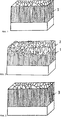
Zur Verdeutlichung soll das am Beispiel von einigen Rasterelektronmikroskopische Aufnahmen (SEM-Abbildungen) von Bruchquerschnitten an Mo-N-, Mo-O, und Mo-N-O-Schichten diskutiert werden.For the sake of clarity, this will be discussed using the example of some scanning electron micrographs (SEM images) of fracture cross sections of Mo-N, Mo-O, and Mo-N-O layers.
In
Die Molybdännitridschichtschicht MoN haben die Erfinder auf einer Haftschicht aus Chromnitrid CrN (Dicke der Haftschicht ca. 300 nm) abgeschieden. Hergestellt wurde die MoN Schicht bei einer Temperatur von 450°C mit einem Mo-Target und einem Funkenstrom von 220 A. Der Stickstoffdruck betrug 3.5 Pa und es wurde ein Substratbias von 20 V verwendet.The molybdenum nitride layer MoN was deposited by the inventors on an adhesion layer of chromium nitride CrN (thickness of the adhesion layer about 300 nm). The MoN layer was produced at a temperature of 450 ° C with a Mo target and a spark current of 220 A. The nitrogen pressure was 3.5 Pa and a substrate bias of 20 V was used.
Die SEM-Aufnahme des Bruchquerschnittes zeigt eine dichte Schichtmorphologie. Härtemessungen ergaben typische Werte von HV 3000 ± 500. Die Schicht zeigte im Vergleich zu gewöhnlich mittels Funkenverdampfung hergestellten Schichten, eine aussergewöhnlich niedrige Rauhigkeit von Rz = 1.07 μm und Ra = 0.13 μm.The SEM image of the fracture cross-section shows a dense layer morphology. Hardness measurements gave typical values of HV 3000 ± 500. The layer exhibited exceptionally low roughness of Rz = 1.07 μm and Ra = 0.13 μm compared to those usually produced by spark evaporation.
Zusätzlich wurden auch die Reibkoeffizienten von den abgeschiedenen Schichten ermittelt. Dafür wurde einen SRV Test bzw. ein Tribometer von der Fa. Optimol Instruments Prüftechnik GmbH angewendet. Bei der Durchführung des SRV Tests wurden die beiden in der Testkammer eingebauten Prüfkörper (eine Kugel auf einer Scheibe) mit vorgegebener Normalkraft aufeinandergepresst. Während der Messung oszillierte der obere Prüfkörper, in diesem Fall der Gegenkörper (eine unbeschichtete Kugel aus Stahl 100Cr6) auf dem unteren Prüfkörper (die beschichtete Prüfscheibe). Für die Messung wurden Frequenz, Gleitweg, Prüfkraft, Prüftemperatur und Prüfdauer vorgegeben. Während der Messung wurden die Reibungskräfte kontinuierlich durch einen Sensor aufgenommen und somit konnten die Reibwerte automatisch berechnet werden. Der während der Messung an beiden Prüfkörpern entstandene Verschleiss wurde auch nach der Messung bewertet.In addition, the coefficients of friction of the deposited layers were also determined. For this purpose an SRV test or a tribometer from the company Optimol Instruments Prüftechnik GmbH was used. When performing the SRV test, the two test specimens installed in the test chamber (one ball on a disk) were pressed together with a given normal force. During the measurement, the upper specimen, in this case the counterbody (an uncoated 100Cr6 steel ball) oscillated on the lower specimen (the coated specimen disc). For the measurement were Frequency, glide path, test load, test temperature and test duration specified. During the measurement, the friction forces were continuously recorded by a sensor and thus the coefficients of friction could be calculated automatically. The wear on both specimens during the measurement was also evaluated after the measurement.
Die gemessenen Reibkoeffizienten und die Beobachtungen hinsichtlich der Aufschmierung des verwendeten Gegenkörpers aus Stahl 100Cr6 auf die mit MoN beschichteten Prüfscheiben im SRV Test sind in der Tabelle 1 aufgelistet. Für alle Messungen im SRV Test wurden die gleichen Parameter hinsichtlich Frequenz, Gleitweg, Prüfkraft, Prüftemperatur und Prüfdauer vorgegeben. Allerdings wurden die Messungen nach drei verschiedenen Testabläufen durchgeführt, wie auch in Tabelle 1 angegeben.The measured coefficients of friction and the observations with regard to the lubrication of the counter body used from 100Cr6 steel to the MoN coated test disks in the SRV test are listed in Table 1. For all measurements in the SRV test, the same parameters were specified with regard to frequency, glide path, test force, test temperature and test duration. However, the measurements were carried out after three different test procedures, as also indicated in Table 1.
Da für alle Messungen ein Gegenkörper bzw. eine Kugel aus Stahl 100Cr6 angewendet wurde, war die Erscheinung von Aufschmierungen vom Stahl auf die Kontaktoberfläche der beschichteten Prüfscheiben zu erwarten, was unter den vorgegebenen Bedingungen gewöhnlich ist. Allerdings haben die Erfinder erstaunlicherweise beobachtet, dass keine Aufschmierung des Gegenkörpers an der Oberfläche der mit MoN beschichteten Prüfscheiben auftrat. Tab. 1: Reibkoeffizienten der mittels Funkenbverdampfung hergestellten MoN-Schichten und Feststellung von Aufschmierung der Gegenkörper auf die Schichten im SRV Test
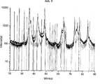
Das XRD Spektrum in
In
Der SEM Bruchquerschnitt zeigt einen deutlichen Übergang zu einem losen Schichtaufbau im letzten Drittel der Schicht (wie in
Die obere Schicht zeigte die lose abgeschiedene MoO3 Schicht, die zwar Schmiereigenschaften aufweist, aber kaum mechanische Festigkeit.The upper layer showed the loosely deposited MoO 3 layer, which has lubricating properties but hardly any mechanical strength.
Es ist dem Fachmann klar, dass der Einbau einer solchen Schicht in ein Schichtsystem zu Haftungsproblemen führt. Die Erfinder führen diesen unerwünschten Aufbau im letzten Drittel der Schicht auf die schnelle Reaktion der Molybdänatome in der Beschichtungskammer und sogar in der schon erzeugten MoN Schicht mit dem in die Beschichtungskammer zugegebenen Sauerstoff zurück. Diese schnelle Reaktion, so vermuten die Erfinder, begünstigt ab einem bestimmten Sauerstofffluss die Formation von flüchtigen Molybdänoxiden, wie MoO2 und MoO3 während der Beschichtung.It is clear to the person skilled in the art that the incorporation of such a layer in a layer system leads to adhesion problems. The inventors attribute this undesirable structure in the last third of the layer to the rapid reaction of the molybdenum atoms in the coating chamber and even in the already produced MoN layer with the oxygen added to the coating chamber. This rapid reaction, the inventors suspect, favors the formation of volatile molybdenum oxides, such as MoO 2 and MoO 3, during the coating from a certain oxygen flux.
Deshalb unterstreicht dieses Ergebnis, dass es sehr wichtig ist, die Sublimation der MoO2 und MoO3 während der Beschichtung zu verhindern. D. h. den Sauerstofffluss so zu kontrollieren, dass im Wesentlichen nur nicht flüchtige Molybdänoxide, wie z. B. Molybdänmonoxid (MoO) in das Schichtsystem eingebaut wird.Therefore, this result emphasizes that it is very important to prevent sublimation of MoO 2 and MoO 3 during coating. Ie. to control the oxygen flow so that essentially only non-volatile molybdenum oxides, such. B. molybdenum monoxide (MoO) is incorporated into the layer system.
Allerdings kann es vorteilhaft sein, dass zum Schichtabschluss erfinderisch absichtlich mit hohem Sauerstofffluss gearbeitet wird, damit es zur Bildung von Molybdäntrioxid (MoO3) an der Schichtoberfläche kommt und somit eine weiche Einlaufschicht erzeugt wird, z. B. MoO3 auf MoO.However, it may be advantageous for the end of the layer to be intentionally worked with high oxygen flux, so that molybdenum trioxide (MoO 3 ) forms on the surface of the layer, thus producing a soft running-in layer, eg. MoO 3 on MoO.
Für die in
Der so gemessene Reibkoeffizient dieser Schichten war 0.75, was erstaunlicherweise höher als der Reibkoeffizient von den reinen MoN Schichten, die bei genau gleichen Testbedingungen (gleiche Testparameter und gleicher Testablauf) im SRV Test charakterisiert wurden. Die Erfinder vermuten, dass dieses unerwartete Ergebnis auf den eventuellen Einbau von Molybdändioxid (MoO2) in die Mo-N-O zurückzuführen ist. Wie in der Literatur bekannt ist und schon oben erwähnt wurde, ist das MoO2 stark abrasiv. Wie die Entstehung von MoO2 beim erfinderischen Herstellungsprozess vermieden werden kann, wird weiter unten beschrieben.The coefficient of friction of these layers measured was 0.75, which was surprisingly higher than the coefficient of friction of the pure MoN layers, which were characterized in exactly the same test conditions (same test parameters and same test procedure) in the SRV test. The inventors suspect that this unexpected result is due to the eventual incorporation of molybdenum dioxide (MoO 2 ) into the Mo-NO. As is known in the literature and has already been mentioned above, the MoO 2 is highly abrasive. How to avoid the formation of MoO 2 in the inventive manufacturing process will be described below.
In
Der erfindungsgemäss durchgeführte Herstellungsprozess führt im Wesentlichen nur zu einer Phasenbildung des Molybdänmonoxids (MoO) in der MoN Schicht, wobei sich die atomare Konzentration des Sauerstoffs in der Moz(NdOe) Schicht zwischen einem Wert von e = 0.03 und 1 unter der Bedingung z ≥ d + e mit d, e und z in at%.The present invention conducted manufacturing process results in essentially only one phase forming the Molybdänmonoxids (MoO) in the MoN layer, wherein the atomic concentration of oxygen in the Mo z (N d O e) layer between a value of e = 0.03 to 1 under the Condition z ≥ d + e with d, e and z in at%.
Der Anteil z – (d + y) von Mo entspricht dann dem nicht mit Stickstoff und/oder Sauerstoff reagiertem Molybdän. Dies tritt dann zum Beispiel beim Funkenverdampfen in Form von in die Schicht eingebauten Konglomeraten auf, die aus nicht vollständig durchreagiertes Molybdän herrühren und in der Fachwelt als Spritzer (Droplets) bekannt sind.The proportion z - (d + y) of Mo then corresponds to the non-reacted with nitrogen and / or oxygen molybdenum. This then occurs, for example, in the case of spark evaporation in the form of conglomerates incorporated into the layer, which are the result of incompletely fully reacted molybdenum and are known in the art as droplets.
Die Schicht, die in
Durch energiedispersive Röntgenmikrobereichsanalyse (EDX) wurde festgestellt, dass die so abgeschiedene erfindungsgemässe Schichten einen Anteil von mehr als 10 at.% Sauerstoff aufweisen.By energy-dispersive X-ray microsphere analysis (EDX) it was found that the layers of the invention deposited in this way have a proportion of more than 10 at.% Oxygen.
Dennoch konnten keine ausgeprägten Molybdändioxid- oder Molybdäntrioxid-Peaks in das XRD-Spektrum dieser Schicht (siehe
Somit zeigt es sich, dass die mit der Funkenverdampfung hergestellten Mo-O Schichten über den Sauerstoffluss so kontrolliert werden können, dass das stabile und duktile MoO (Molybdänmonoxid) hergestellt werden kann und in eine MoN Matrix eingebaut werden kann oder auch als Einzelschicht synthetisiert werden kann. Der Übergang zu MoO3 ohne oder mit sehr wenig Einbau vom abrasiven MoO2 in die Schicht, lässt sich in einer schnellen Oxidrampe realisieren und damit ist die Herstellung einer festen Oberflächenschmierung im gleichen Prozess möglich.Thus, it turns out that the Mo-O layers produced by the sputtering can be controlled by the oxygen flux so that the stable and ductile MoO (molybdenum monoxide) can be prepared and incorporated into a MoN matrix or synthesized as a single layer , The transition to MoO 3 without or with very little incorporation of the abrasive MoO 2 in the layer, can be realized in a fast oxide ramp and thus the production of a solid surface lubrication in the same process is possible.
Wie oben bereits erwähnt eignet sich eine derart hergestellte äussere MoO3-Schicht besonders gut als Einlaufschicht.As already mentioned above, an outer MoO 3 layer produced in this way is particularly suitable as a running-in layer.
Durch die Flexibilität der erfindungsgemässen angewendeten Funkenverdampfenund gepulsten Funkenverdampfensprozessen können auch erfindungsgemäss MoO Schichten in jede beliebige Schicht eingebaut werden. Die MoO Schichten und MoO + MoO3 Schichten, wobei MoO3 als Einlaufschicht verwendet wird, werden insbesondere als äussere Schichten eingebaut, um eine bestimmte Weichheit oder ein verbessertes Einlaufverhalten im Vergleich zum ursprünglichen Schichtsystem einstellen zu können, damit zum Beispiel der Verschleiss vom Gegenkörpern in einem tribologischen System minimiert wird und gleichzeitig ein stabilisiertes Oxidationsverhalten von Mo-haltigen Schichten vorhanden ist.Due to the flexibility of the inventive applied spark vaporization and pulsed spark vaporization processes, it is also possible according to the invention for MoO layers to be incorporated in any desired layer. The MoO layers and MoO + MoO 3 layers, where MoO 3 is used as the inlet layer, In particular, they are incorporated as outer layers in order to be able to set a certain softness or an improved run-in behavior compared to the original layer system, for example to minimize the wear of the counter-bodies in a tribological system and at the same time a stabilized oxidation behavior of Mo-containing layers is present.
Von Vorteil ist auch den Einbau von MoO in jeder beliebigen Schicht und insbesondere in anderen Oxidschichten, wie z. B. Al-O, CrO, Zr-O, Ti-O und/oder auch in Mischoxidschichten, wie z. B. (Al, Cr)O, (Zr, Cr)O oder Cr-O um z. B. Geschmeidigkeit einzustellen.Another advantage is the incorporation of MoO in any layer and in particular in other oxide layers, such as. As Al-O, CrO, Zr-O, Ti-O and / or in mixed oxide layers, such as. B. (Al, Cr) O, (Zr, Cr) O or Cr-O by z. B. adjust suppleness.
Dafür muss die Reaktivität von den anderen Elementen gegenüber dem Sauerstoff sehr genau betrachtet werden. Man kann zum Beispiel durch verschiedene Versuche je mit schrittweise erhöhtem Sauerstofffluss analysieren, ab welchem Sauerstofffluss Molybdändioxid und Molybdäntrioxid in die Schicht formiert werden. Bleibt man im eigentlichen Beschichtungsprozess dann bei niedrigeren Sauerstoffflüssen, so wird die Formierung von den unerwünschten Molybdänoxiden vermeiden.For this, the reactivity of the other elements to the oxygen must be considered very closely. For example, by means of various experiments, it is possible to analyze with increasing oxygen flux from which oxygen flow molybdenum dioxide and molybdenum trioxide are formed in the layer. If one then remains in the actual coating process at lower oxygen fluxes, the formation of the unwanted molybdenum oxides will be avoided.
Wie die Erfinder ermitteln konnten, ist es von besonderem Vorteil, zwischen der MoO Schicht und dem Substrat eine MoN enthaltende Schicht vorzusehen. Hierdurch wird die mechanische Stabilität der Schicht am Beispiel von der Härte und der Haftfestigkeit innerhalb der Schicht auch weiter verbessert.As the inventors have been able to determine, it is of particular advantage to provide a MoN-containing layer between the MoO layer and the substrate. As a result, the mechanical stability of the layer is further improved by the example of the hardness and the adhesive strength within the layer.
Es kann dann von Vorteil sein, neben dem Molybdän noch weitere Metallkomponenten in der Schicht vorzusehen.It may then be advantageous to provide, in addition to the molybdenum, further metal components in the layer.
Eine besonders bevorzugte Variante der Erfindung ist die Herstellung eines Mo-N-O Schicht mittels Funkenverdampfen und/oder gepulstem Funkenverdampfen, die z. B. folgendes hergestellt werden kann:
- • Nach Einlassen von Stickstoff in die Beschichtungskammer wird in der Stickstoffatmosphäre auf einem als Kathode dienenden Molybdäntarget ein Funken gezündet, wodurch es zur Verdampfung von Molybdän und/oder bereits reagiertem Molybdännitrit kommt. Nach Erreichung einer bestimmten Schichtdicke wird zusätzlich in die Beschichtungskammer wenig Sauerstoff eingelassen und somit eine Mo-N-O Schicht hergestellt, die die sehr guten Eigenschaften von Mo-N aufweist aber zusätzlich aufgrund der in Schicht eingebauten kleinen Mengen von Mo-O Verbindungen auch verbesserte Schmierstoffeigenschaften und/oder Geschmeidigkeit bietet.
- • Nach Einlassen von Stickstoff in die Beschichtungskammer wird in der Stickstoffatmosphäre auf einem als Kathode dienenden Molybdäntarget ein Funken gezündet, wodurch es zur Verdampfung von Molybdän und/oder bereits reagiertem Molybdännitrit kommt. Nach Erreichung einer bestimmten Schichtdicke wird zusätzlich in die Beschichtungskammer wenig Sauerstoff eingelassen und nach einer bestimmten Zeit der Sauerstofffluss nochmals abgebrochen, so dass weiter wieder nur Molybdännitrid erzeugt wird. Der Beschichtungsprozess wird so alternierend weitergeführt bis der gewünschten gesamten Schichtdicke der mehrlagigen Schicht Mo-N/Mo-N-O/Mo-N/Mo-N-O... erreicht wird. Die Dicke der Einzelllagen so wie die gesamte Schichtdicke wird anwendungsbezogen angepasst. Auch mit dieser Variante werden in einer einzigen Beschichtung die sehr guten Eigenschaften von Mo-N und die Schmierstoffeigenschaften und/oder Geschmeidigkeit von Mo-O kombiniert.
- After introducing nitrogen into the coating chamber, a spark is ignited in the nitrogen atmosphere on a molybdenum target serving as a cathode, resulting in the evaporation of molybdenum and / or already reacted molybdenum nitrite. After reaching a certain layer thickness is additionally introduced into the coating chamber little oxygen and thus a Mo-NO layer produced which has the very good properties of Mo-N but also due to the incorporated in layer small amounts of Mo-O compounds also improved lubricant properties and / or provides suppleness.
- After introducing nitrogen into the coating chamber, a spark is ignited in the nitrogen atmosphere on a molybdenum target serving as a cathode, resulting in the evaporation of molybdenum and / or already reacted molybdenum nitrite. After reaching a certain layer thickness, in addition, little oxygen is introduced into the coating chamber and, after a certain time, the oxygen flow is stopped again, so that again only molybdenum nitride is produced. The coating process is continued in an alternating manner until the desired total layer thickness of the multilayered layer Mo-N / Mo-NO / Mo-N / Mo-NO... Is reached. The thickness of the individual layers as well as the total layer thickness is adapted to the application. Also with this variant, the very good properties of Mo-N and the lubricant properties and / or suppleness of Mo-O are combined in a single coating.
Ähnliche Schichtsysteme lassen sich auch mit legierten Targets von Mo in Kombination mit anderen Metallen herstellen, oder indem man ausser das Mo-Target oder die Mo-Targets auch Targets aus anderen Metallen und/oder Legierungen und/oder anderen Materialien während der Beschichtungsprozess aktiviert bzw. verdampfen lässt.Similar layer systems can also be produced with alloyed targets of Mo in combination with other metals, or by activating targets of other metals and / or alloys and / or other materials during the coating process in addition to the Mo target or the Mo targets. evaporates.
Zur Herstellung von ähnlichen Schichtsystemen wie die bereits oben erwähnten aber mit besonderen mechanischen Eigenschaften haben die Erfinder auch erfindungsgemäss Schichtsysteme, die Karbide umfassen vorgesehen. Diese Schichtsysteme werden auch mittels Funkenverdampfen und/oder gepulstem Funkenverdampfen indem während der Beschichtung zusätzlich ein kohlenstoffhaltiges Gas eingelassen wird und/oder durch die Aktivierung bzw. Verdampfung von Kohlenstoff-Targets und/oder kohlenstoffhaltigen Targets Allgemein ausgedrückt liegt dann ein erfindungsgemässes Schichtsystem gemäss einer besonders bevorzugten Variante vor, wenn mindestens zwei Schichten umfasst:
- • Eine erste Schicht, die als Hauptbestandteil MoN aufweist und damit sehr gute mechanische Stabilität besitzt und
- • Eine zweite Schicht, die als Hauptbestandteil Molybdänmonoxid aufweist und damit sehr gute Schmierstoffeigenschaften besitzt.
- • A first layer, which has MoN as main component and thus has very good mechanical stability and
- • A second layer that contains molybdenum monoxide as the main component and therefore has very good lubricant properties.
Der Übergang zwischen erster und zweiter Schicht kann graduell ausgebildet sein.The transition between first and second layer may be formed gradually.
Eine wesentliche Verbesserung der Zähigkeit erreicht man durch die Abscheidung von mehrlagigen Schichten. Gleichzeitig wird auf diese Weise eine Rissausbreitung von der Oberfläche zum Grundwerkstoff hin unterbunden. Des Weiteren kann in vielen Fällen die maximale Schichtdicke gesteigert werden, da mit dem mehrlagigen Schichtverbund mechanische Eigenspannungen in der Schicht im Vergleich zur Monolagenschicht reduziert werden können. A significant improvement in toughness is achieved by the deposition of multilayer coatings. At the same time, crack propagation from the surface to the base material is prevented in this way. Furthermore, in many cases, the maximum layer thickness can be increased, since mechanical stresses in the layer can be reduced in comparison with the monolayer layer with the multilayer composite layer.
Um eine gute Festigkeit innerhalb der gesamten Schicht zu gewährleisten, ist eine entsprechende Anpassung der Werkstoffeigenschaften der verschiedenen Lagen erforderlich. Das kann zum Beispiel durch die Erzeugung gradierter Grenz/Übergangsschichten oder durch die Abscheidung von Zwischenlagen erzielt werden.In order to ensure a good strength within the entire layer, a corresponding adjustment of the material properties of the various layers is required. This can be achieved, for example, by the creation of graded boundary / transition layers or by the deposition of intermediate layers.
Detaillierte Beschreibung der Erfindung anhand von BeispielenDetailed description of the invention by way of examples
Die folgenden Beispiele dienen dazu, die Erfindung im Detail darzulegen, sie sollten jedoch nicht als eine Beschränkung deren Umfang angesehen werden.The following examples serve to illustrate the invention in detail, but they should not be construed as limiting the scope thereof.
Beispiel 1: Allgemein ist von Vorteil, dass Kolbenringe und Wellendichtringe über gute mechanische Stabilität und gleichzeitig gute Schmierstoffeigenschaften und/oder Geschmeidigkeit verfügen. Im vorliegenden Beispiel wurde einen Kolbenring aus rostfreiem Stahl mittel Funkenverdampfen mit Mo-N beschichtet. Hierzu wird der Kolbenring in die Beschichtungskammer einer Beschichtungsanlage platziert. Die Beschichtungskammer wird evakuiert und zur Reinigung/Aktivierung der Oberfläche wird die Oberfläche vor der Beschichtung geheizt und geätzt. Nach Einlassen von Stickstoff in die Beschichtungskammer wird in der Stickstoffatmosphäre auf einem als Kathode dienenden Molybdäntarget ein Funken gezündet, wodurch es zur Verdampfung von Molybdän und/oder bereits reagiertem Molybdännitrit kommt. Abscheiden des Materials auf der Kolbenoberfläche führt zur Bildung einer 2 μm dicken Mo-N-Schicht. Das Beschichtungsverfahren erlaubt die anwendungsbezogene Anpassung der Schichtdicke.Example 1: It is generally advantageous that piston rings and shaft sealing rings have good mechanical stability and at the same time good lubricant properties and / or suppleness. In the present example, a stainless steel piston ring was sputter-coated with Mo-N. For this purpose, the piston ring is placed in the coating chamber of a coating system. The coating chamber is evacuated and, to clean / activate the surface, the surface is heated and etched prior to coating. After introducing nitrogen into the coating chamber, a spark is ignited in the nitrogen atmosphere on a molybdenum target serving as a cathode, resulting in the evaporation of molybdenum and / or already reacted molybdenum nitrite. Depositing the material on the piston surface results in the formation of a 2 μm thick Mo-N layer. The coating process allows the application-specific adaptation of the layer thickness.
Durch die erfindungsgemässe Beschichtung mittels Funkverdampfung mit Mo-N vom Kolben sind die Erfinder darauf gekommen, dass die Reibung während des Betriebs deutlich reduziert wird und auch die Lebensdauer des Kolbenringes deutlich erhöht wird. Die Erfinder führen die verminderte Reibung u. a. auf die durch das Funkenverdampfen in die Schicht eingebauten Spritzer zurück. Diese Spritzer sind zahlenmässig so gering, dass sie die Stabilität und damit die Härte des Mo-N nicht wesentlich beeinträchtigen, jedoch so zahlreich vorhanden, dass das so vorhandene Molybdän die bereits guten Gleiteigenschaften der durch den Herstellungsprozess glatten Mo-N Schicht durch seine Schmierstoffeigenschaften noch weiter verbessert.Due to the inventive coating by means of radio-evaporation with Mo-N from the piston, the inventors have come to the fact that the friction during operation is significantly reduced and also the life of the piston ring is significantly increased. The inventors lead the reduced friction u. a. back to the built-in by the spark evaporation in the layer splashes. These splashes are numerically so small that they do not significantly affect the stability and thus the hardness of the Mo-N, but so abundant that the existing molybdenum the already good sliding properties of the smooth by the manufacturing process Mo-N layer by its lubricant properties further improved.
Ein besonderer Vorteil des Funkenverdampfens ist die Möglichkeit, Funktionsflächen von Präzisionsbauteilen zu beschichten da Schichtdicken genau gemäss der erforderlichen Präzision bzw. den Massgaben im tribologischen System abgeschieden werden könnenA particular advantage of spark evaporation is the ability to coat functional surfaces of precision components since layer thicknesses can be deposited precisely in accordance with the required precision or the requirements in the tribological system
Wird beim oben genannten Beschichtungsverfahren Pulstechnologie eingesetzt so kann das Wachstum verschiedener Phasen vom Mo-N durch die Einstellung verschiedener Pulsparameter bei der Anlegung einer gepulsten Biasspannung und/oder beim Betrieb einer gepulsten Funkverdampfungsquelle sehr gut reguliert werden. Hierdurch wird ermöglicht, dass durch eine bestimmte Einstellung der Beschichtungsparameter, insbesondere der Pulsparameter, das Wachstum einer bestimmten Phase begünstigt wird und Mo-N Schichten mit besonderen Eigenschaften, angepasst an die Verwendung des beschichteten Bauteils, hergestellt werden können. Es ist auch möglich durch Variation der Beschichtungsparameter während des Beschichtens mehrlagige Mo-N Schichten mit verschiedenen Phasen beispielsweise auch abgewechselt aufzubauen. Insbesondere kann somit ein Schichtsystem aufgebaut werden, bei dem sich kubisches Mo-N mit hexagonalem Mo-N abwechseln. Ein solches, mindestens zwei Schichten umfassendes Schichtsystem umfasst dann zumindest eine innere kubische und damit harte Schicht und eine äussere hexagonale und damit weichere Schicht.If pulse technology is used in the above-mentioned coating method, the growth of various phases of Mo-N can be very well regulated by setting various pulse parameters when applying a pulsed bias voltage and / or operating a pulsed radio-frequency source. This makes it possible that by a certain adjustment of the coating parameters, in particular the pulse parameters, the growth of a particular phase is favored and Mo-N layers with special properties, adapted to the use of the coated component, can be produced. It is also possible, by varying the coating parameters during coating, to build up multilayered Mo-N layers with different phases, for example alternately. In particular, a layer system can thus be constructed in which cubic Mo-N alternate with hexagonal Mo-N. Such a layer system comprising at least two layers then comprises at least one inner cubic and therefore hard layer and an outer hexagonal and therefore softer layer.
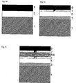
Gemäss einer weiteren Ausführungsform der vorliegenden Erfindung wird, z. B. bei besonders hochbeanspruchte Kolben in Verbrennungsmotoren oder auch, um auf externe Zwischenstoffe verzichten zu können, ein zweilagiges Schichtsystem auf die Funktionsfläche bzw. auf dem Substrat
Auch hier kann, wie bereits weiter oben beschrieben, eine zusätzliche Haftschicht vorgesehen sein, wie in
Der Übergang zwischen der ersten Schicht
Eine weitere Verbesserung der Zähigkeit im Schichtsystem kann durch die Abscheidung von mehreren nanolagigen Schichten, oder durch die Herstellung von Nanoverbundstrukturen in dem zum Beispiel die härtere Phase in der Form von Nanokörnern in einer Matrix aus der weicheren Phase eingebetet ist.A further improvement in toughness in the layer system may be due to the deposition of several nanolagic layers, or by the production of nanocomposite structures in which, for example, the harder phase is embedded in the form of nanospheres in a matrix of the softer phase.
Von X-Schicht ist im Rahmen der vorliegenden Beschreibung dann die Rede, wenn die Schicht überwiegend X enthält, wobei X ein elementarer Stoff oder eine Verbindung sein kann.X-layer is used in the context of the present description when the layer predominantly contains X, where X may be an elementary substance or a compound.
Im Rahmen der vorliegenden Beschreibung wurde eine Beschichtung offenbart, die mindestens eine molybdänhaltige Schicht mit Molybdänoxid umfasst und die dadurch gekennzeichnet ist, dass das Molybdänoxid im Wesentlichen Molybdänmonoxid ist.In the context of the present description, a coating has been disclosed which comprises at least one molybdenum-containing layer with molybdenum oxide and which is characterized in that the molybdenum oxide is essentially molybdenum monoxide.
Die erfindungsgemässe Beschichtung kann zum Beispiel eine Molybdänoxidschicht enthalten, die im Wesentlichen Molybdänmonoxid umfasst. Eine Schicht MoO-Schicht lässt sich von MoO2- und MoO3-Schichten unterscheiden indem zum Beispiel das XRD Spektrum der Molybdänmonoxidschicht (MoO) im Wesentlichen weder MoO2 Peaks noch MoO3 Peaks aufweist.The coating according to the invention may, for example, contain a molybdenum oxide layer which essentially comprises molybdenum monoxide. A layer of MoO layer can be differentiated from MoO 2 and MoO 3 layers by, for example, the XRD spectrum of the molybdenum monoxide layer (MoO) having essentially neither MoO 2 peaks nor MoO 3 peaks.
Eine bevorzugte Variante der erfindungsgemässen Beschichtung kann zum Beispiel zusätzlich auch eine Molybdännitridschicht umfassen.A preferred variant of the coating according to the invention may, for example, additionally comprise a molybdenum nitride layer.
Die erfindungsgemässe Beschichtung kann auch eine Mo-N-O Schicht enthalten, die Molybdänstickstoffbindungen und Molybdänoxidbindungen umfasst, wobei im Wesentlichen die Molybdänatome maximal mit einem Sauerstoffatom eine Verbindung bilden und in der Beschichtung vorzugsweise Molybdänmonoxid enthalten ist.The coating according to the invention can also contain a Mo-N-O layer which comprises molybdenum nitrogen bonds and molybdenum oxide bonds, with essentially the molybdenum atoms forming a compound with an oxygen atom at most and molybdenum monoxide preferably being present in the coating.
Eine bevorzugte Variante der erfindungsgemässen Beschichtung mit mindestens einer Mo-N-O Schicht charakterisiert sich indem die Mo-N-O Schicht zwischen einer Molybdännitridschicht und einer Molybdänmonoxidschicht liegt.A preferred variant of the coating according to the invention with at least one Mo-N-O layer is characterized in that the Mo-N-O layer lies between a molybdenum nitride layer and a molybdenum monoxide layer.
Das atomare Konzentrationsverhältnis in der Mo-N-O Schicht kann durch die folgende Formel beschrieben werden: Moz(NdOe) wobei:
e: die atomare Sauerstoffkonzentration in der Mo-N-O Schicht ist
d: die atomare Stickstoffkonzentration in der Mo-N-O Schicht ist
z: die atomare Molybdänkonzentration in der Mo-N-O Schicht ist und z ≥ y.The atomic concentration ratio in the Mo-NO layer can be described by the following formula: Mo z (N d O e ) where:
e: the atomic oxygen concentration in the Mo-NO layer
d: is the atomic nitrogen concentration in the Mo-NO layer
z: the atomic molybdenum concentration in the Mo-NO layer is and z ≥ y.
Die Mo-N-O Schicht kann auch eine gradierte Schicht sein, wobei die Stickstoffkonzentration von der substratnahen Grenzfläche zur oberflächennahen Grenzfläche der Md-N-O-Schicht abnimmt während die Sauerstoffkonzentration zunimmt.The Mo-N-O layer may also be a graded layer, with the nitrogen concentration decreasing from the substrate-near interface to the near-surface interface of the Md-N-O layer as the oxygen concentration increases.
Ebenfalls kann die Mo-N-O Schicht, eine gradierte Schicht sein, wobei die Sauerstoffkonzentration von der substratnahen Grenzfläche zur oberflächennahen Grenzfläche der Mo-N-O-Schicht abnimmt während die Stickstoffkonzentration zunimmt.Also, the Mo-N-O layer may be a graded layer wherein the oxygen concentration decreases from the substrate-near interface to the near-surface interface of the Mo-N-O layer while the nitrogen concentration increases.
Eine erfindungsgemässe Beschichtung kann auch als mehrlagiges Schichtsystem abgeschieden werden, wobei mehrere MoN- und MoO-Schichten alternierend abgeschieden werden und können auch z. B. mehrere Mo-N-O Schichten enthalten, die z. B. zwischen den MoN- und MoO-Schichten liegen und die als gradierte Schichten mit angepassten Variationen der Stickstoff- und Sauerstoffkonzentrationen zur Verbesserung der Haftfestigkeit innerhalb der Schicht abgeschieden werden können.A coating according to the invention can also be deposited as a multilayer coating system, wherein several MoN and MoO layers are deposited alternately and can also be applied, for example, to B. contain multiple Mo-N-O layers, the z. B. between the MoN and MoO layers and can be deposited as graded layers with adapted variations of the nitrogen and oxygen concentrations to improve the adhesion within the layer.
Die erfindungsgemässe Beschichtung kann auch zusätzlich eine Deckschicht mit MoO3, wenn das MoO3 anwendungsbezogen weitere Vorteile mitbringen kann.The coating according to the invention can also additionally have a covering layer with MoO 3 , if the MoO 3 can bring about further advantages related to the application.
Erfindungsgemäss kann auch die Beschichtung zwischen dem Grundkörper und der Mo-haltigen Schicht eine oder mehrere Haftschichten) und/oder Funktionsschichten) umfassen. According to the invention, the coating between the main body and the Mo-containing layer can also comprise one or more adhesive layers and / or functional layers.
Eine auch bevorzugte Variante der Erfindung ist eine Beschichtung die mindestens eine Mo-haltige umfasst, die insbesondere sehr gute mechanische Stabilität aufweist und (Mo1-x, Mex)AaBbCc, enthält, wobei 0 ≤ x ≤ 0.99, vorzugsweise 0 ≤ x ≤ 0.5 und
Me ein Metal aus der Gruppe von W, Ti, Al, Cr, Si, Zr, Ta, Nb, Ag, Cu und V ist, oder der Kombination aus zwei oder mehreren Metallen dieser Gruppe und
- A: Stickstoff (N) ist mit 0.5 ≤ a ≤ 1
- B: Kohlenstoff (C) ist mit 0 ≤ b ≤ 0.5
- C: Sauerstoff (O) ist mit 0 ≤ c ≤ 0.5
Me is a metal from the group of W, Ti, Al, Cr, Si, Zr, Ta, Nb, Ag, Cu and V, or the combination of two or more metals of this group and
- A: Nitrogen (N) is 0.5 ≤ a ≤ 1
- B: Carbon (C) is 0≤b≤0.5
- C: oxygen (O) is 0≤c≤0.5
Ebenso ist eine bevorzugte Variante der Erfindung eine Beschichtung die mindestens eine Mo-haltige Schicht umfasst, die insbesondere sehr gute Schmierstoffeigenschaften und Gleiteigenschaften aufweist und (Mo1-y, Mey)AuBvCw, enthält, wobei 0 ≤ y ≤ 0.99, vorzugsweise 0 ≤ y ≤ 0.5 und
Me ein Metal aus der Gruppe von W, Ti, Al, Cr, Si, Zr, Ta, Nb, Ag, Cu und V ist, oder der Kombination aus zwei oder mehreren Metallen dieser Gruppe und
- A: Stickstoff ist mit 0 ≤ u ≤ 0.5
- B: Kohlenstoff ist mit 0 ≤ v ≤ 0.5
- C: Sauerstoff ist mit 0.5 ≤ w ≤ 1
Me is a metal from the group of W, Ti, Al, Cr, Si, Zr, Ta, Nb, Ag, Cu and V, or the combination of two or more metals of this group and
- A: Nitrogen is 0 ≤ u ≤ 0.5
- B: Carbon is with 0 ≤ v ≤ 0.5
- C: Oxygen is 0.5 ≤ w ≤ 1
Bevorzugt konnte auch erfindungsgemäss eine Beschichtung so aufgebaut werden, die
- • mindestens eine erste Mo-haltige Schicht, die insbesondere eine sehr gute mechanische Stabilität aufweist (gemäss der oben beschriebene (Mo1-x, Mex)AaBbCc Schicht) und
- • mindestens eine zweite Schicht, die insbesondere sehr gute Schmierstoffeigenschaften und Gleiteigenschaften aufweist (gemäss der oben beschriebene (Mo1-y, Mey)AuBcCw Schicht)
- At least one first Mo-containing layer which in particular has a very good mechanical stability (according to the (Mo 1-x , Me x ) A a B b C c layer described above) and
- At least one second layer which in particular has very good lubricant properties and sliding properties (according to the (Mo 1-y , Me y ) A u B c C w layer described above)
Eine bevorzugte Variante des Verfahrens zur Herstellung der erfindungsgemässen Beschichtung ist ein PVD-Verfahren oder kombiniertes PVD/CVD Verfahren, wobei das Molybdänmonoxid in der Molybdänmonoxid umfassenden Schicht mittels Funkenverdampfen abgeschieden wird.A preferred variant of the process for producing the coating according to the invention is a PVD process or combined PVD / CVD process, wherein the molybdenum monoxide is deposited in the layer comprising molybdenum monoxide by means of spark evaporation.
Eine weitere bevorzugte Variante des Verfahrens zur Herstellung der erfindungsgemässen Beschichtung ist ein PVD-Verfahren, wobei die molybdänhaltigen Schichten mittels Funkenverdampfen von mindestens einem molybdänhaltigen Target in Reaktivatmosphäre hergestellt werden.A further preferred variant of the method for producing the coating according to the invention is a PVD method, wherein the molybdenum-containing layers are produced by spark evaporation of at least one molybdenum-containing target in a reactive atmosphere.
Als Materialquelle für die molybdänhaltigen Schichten können sowohl Molybdäntargets als auch legierte molybdänhaltige Targets angewendet werden, die zum Beispiel schmelzmetallurgisch oder pulvermetallurgisch hergestellt werden können.As a material source for the molybdenum-containing layers, both molybdenum targets and alloyed molybdenum-containing targets can be used, which can be produced, for example, by melt metallurgy or powder metallurgy.
Bauteile können anwendungsbezogen mit der besser geeigneter Variante der erfindungsgemässen Beschichtung beschichtet werden.Components can be coated with the application of the more suitable variant of the coating according to the invention.
Insbesondere können Zerspanungswerkzeugen und Umformwerkzeugen, die zur Fertigung von Bauteilen aus Metallen oder Metalllegierungen erfindungsgemäss beschichtet werden, um Aufschmierungen der bearbeiteten Metalle oder Metalllegierungen auf die beschichtete Oberfläche des Werkzeugs zu reduzieren oder vorzugsweise vollständig zu vermieden.In particular, cutting tools and forming tools which are coated according to the invention for the production of components made of metals or metal alloys, in order to reduce or preferably completely avoid lube deposits of the processed metals or metal alloys on the coated surface of the tool.
Bildlegende:Caption:
BezugszeichenlisteLIST OF REFERENCE NUMBERS
- 11
- Substratsubstratum
- 33
- Haftschicht und/oder FunktionsschichtAdhesive layer and / or functional layer
- 55
- Erste SchichtFirst shift
- 77
- ÜbergangsschichtTransition layer
- 99
- Zweite SchichtSecond shift
ZITATE ENTHALTEN IN DER BESCHREIBUNG QUOTES INCLUDE IN THE DESCRIPTION
Diese Liste der vom Anmelder aufgeführten Dokumente wurde automatisiert erzeugt und ist ausschließlich zur besseren Information des Lesers aufgenommen. Die Liste ist nicht Bestandteil der deutschen Patent- bzw. Gebrauchsmusteranmeldung. Das DPMA übernimmt keinerlei Haftung für etwaige Fehler oder Auslassungen.This list of the documents listed by the applicant has been generated automatically and is included solely for the better information of the reader. The list is not part of the German patent or utility model application. The DPMA assumes no liability for any errors or omissions.
Zitierte PatentliteraturCited patent literature
- DE 102006036101 A1 [0004, 0006, 0006] DE 102006036101 A1 [0004, 0006, 0006]
- US 20090256215 [0007] US 20090256215 [0007]
- DE 19944977 B4 [0014, 0019] DE 19944977 B4 [0014, 0019]
- DE 29620687 U1 [0016] DE 29620687 U1 [0016]
- SU 1832751 A1 [0017] SU 1832751 A1 [0017]
- JP 2006255708 [0018] JP 2006255708 [0018]
- US 2010078314 A1 [0019] US 2010078314 A1 [0019]
- WO 9521994 A1 [0019] WO 9521994 A1 [0019]
- EP 1783244 [0020] EP 1783244 [0020]
Zitierte Nicht-PatentliteraturCited non-patent literature
- Surface and Coatings Technology 163–164 (2003) 413–421 [0008] Surface and Coatings Technology 163-164 (2003) 413-421 [0008]
- Journal of Materials Science Letters 5 (1986) 255–256 [0010] Journal of Materials Science Letters 5 (1986) 255-256 [0010]
- Surface and Coatings Technology 163–164 (2003) 413–421 [0010] Surface and Coatings Technology 163-164 (2003) 413-421 [0010]
- Surface and Coating Technology 167 (2003) 77–82 [0011] Surface and Coating Technology 167 (2003) 77-82 [0011]
- Surface and Coating Technology 167 (2003) 77–82 [0013] Surface and Coating Technology 167 (2003) 77-82 [0013]
- Surface and Coatings Technology 174–175 (2003) 713–719 [0015] Surface and Coatings Technology 174-175 (2003) 713-719 [0015]
Claims (18)
Priority Applications (13)
| Application Number | Priority Date | Filing Date | Title |
|---|---|---|---|
| EP11779086.5A EP2633095B1 (en) | 2010-10-28 | 2011-10-06 | Molybdenum monoxide layers, and production thereof using pvd |
| BR112013010147A BR112013010147A2 (en) | 2010-10-28 | 2011-10-06 | molybdenum monoxide layers and their production through pvd |
| PCT/EP2011/004990 WO2012055485A1 (en) | 2010-10-28 | 2011-10-06 | Molybdenum monoxide layers, and production thereof using pvd |
| MX2013004780A MX350887B (en) | 2010-10-28 | 2011-10-06 | Molybdenum monoxide layers, and production thereof using pvd. |
| US13/881,855 US9822322B2 (en) | 2010-10-28 | 2011-10-06 | Molybdenum monoxide layers, and production thereof using PVD |
| SG2013032081A SG190021A1 (en) | 2010-10-28 | 2011-10-06 | Molybdenum monoxide layers, and production thereof using pvd |
| RU2013124399A RU2622553C2 (en) | 2010-10-28 | 2011-10-06 | Monoxide molybdenum layers, and their obtaining by means of pv |
| KR1020137013593A KR101930564B1 (en) | 2010-10-28 | 2011-10-06 | Molybdenum monoxide layers, and production thereof using pvd |
| JP2013535294A JP2013545893A (en) | 2010-10-28 | 2011-10-06 | Molybdenum monoxide layer and its production method using physical vapor deposition (PVD) |
| CA2815911A CA2815911A1 (en) | 2010-10-28 | 2011-10-06 | Molybdenum monoxide layers, and production thereof using pvd |
| CN201180063789.XA CN103270188B (en) | 2010-10-28 | 2011-10-06 | Molybdous oxide layer and the preparation by PVD thereof |
| MYPI2013001508A MY179397A (en) | 2010-10-28 | 2011-10-06 | Molybdenum monoxide layers, and production thereof using pvd |
| JP2017170564A JP2018035442A (en) | 2010-10-28 | 2017-09-05 | Molybdenum monoxide layer, and its preparation using physical vapor deposition (pvd) |
Applications Claiming Priority (2)
| Application Number | Priority Date | Filing Date | Title |
|---|---|---|---|
| US40765610P | 2010-10-28 | 2010-10-28 | |
| US61/407,656 | 2010-10-28 |
Publications (1)
| Publication Number | Publication Date |
|---|---|
| DE102010053751A1 true DE102010053751A1 (en) | 2012-05-03 |
Family
ID=45935681
Family Applications (1)
| Application Number | Title | Priority Date | Filing Date |
|---|---|---|---|
| DE102010053751A Withdrawn DE102010053751A1 (en) | 2010-10-28 | 2010-12-08 | Molybdenum monoxide layers and their production by PVD |
Country Status (13)
| Country | Link |
|---|---|
| US (1) | US9822322B2 (en) |
| EP (1) | EP2633095B1 (en) |
| JP (2) | JP2013545893A (en) |
| KR (1) | KR101930564B1 (en) |
| CN (1) | CN103270188B (en) |
| BR (1) | BR112013010147A2 (en) |
| CA (1) | CA2815911A1 (en) |
| DE (1) | DE102010053751A1 (en) |
| MX (1) | MX350887B (en) |
| MY (1) | MY179397A (en) |
| RU (1) | RU2622553C2 (en) |
| SG (1) | SG190021A1 (en) |
| WO (1) | WO2012055485A1 (en) |
Cited By (6)
| Publication number | Priority date | Publication date | Assignee | Title |
|---|---|---|---|---|
| DE102012207814A1 (en) * | 2012-05-10 | 2013-11-14 | Mahle International Gmbh | Component, preferably sliding element comprises a substrate element, and a protective coating applied on the substrate element, comprising a primary layer, whose primary components are molybdenum and nitrogen |
| DE102012207813A1 (en) * | 2012-05-10 | 2013-11-14 | Mahle International Gmbh | Sliding body with coating |
| WO2014056605A1 (en) * | 2012-10-10 | 2014-04-17 | Oerlikon Trading Ag, Trübbach | Coatings for high-temperatures uses with tri-biological stress |
| DE102012017033A1 (en) * | 2012-08-29 | 2014-05-28 | Oerlikon Trading Ag, Trübbach | PVD arc coating with improved friction-reducing and wear-reducing properties |
| DE102012023260A1 (en) * | 2012-11-29 | 2014-06-05 | Oerlikon Trading Ag, Trübbach | Process for structuring layer surfaces and device for this |
| WO2015096882A2 (en) | 2013-11-29 | 2015-07-02 | Oerlikon Trading Ag, Trübbach | Coating comprising a mo-n-based layer in which the molybdenum nitride is provided as a delta phase |
Families Citing this family (12)
| Publication number | Priority date | Publication date | Assignee | Title |
|---|---|---|---|---|
| DE102012200378A1 (en) * | 2012-01-12 | 2013-07-18 | Federal-Mogul Burscheid Gmbh | piston ring |
| CN104471101B (en) * | 2012-03-12 | 2017-08-08 | 欧瑞康表面解决方案股份公司,普费菲孔 | Coating with enhanced sliding property |
| CN104812925B (en) * | 2012-08-29 | 2017-07-18 | 欧瑞康表面解决方案股份公司,普费菲孔 | With enhanced antifriction and the electric arc PVD coatings for subtracting abrasive nature |
| CN104372299B (en) * | 2013-09-23 | 2017-08-04 | 中国科学院合肥物质科学研究院 | Sandwich construction hard, wear-resisting, lubricant coating and preparation method thereof |
| CN103789725B (en) * | 2014-01-29 | 2016-08-31 | 仪征亚新科双环活塞环有限公司 | Multilamellar multiple elements design hard PVD coating, piston ring and the preparation technology of a kind of piston ring surface |
| JP6257837B2 (en) | 2014-07-24 | 2018-01-10 | エリコン・サーフェス・ソリューションズ・アクチェンゲゼルシャフト,プフェフィコーンOerlikon Surface Solutions Ag, Pfaeffikon | Arc deposition Me11-aMe2aZI / Mo1-b-cSicBbZII multilayer coating |
| KR101673712B1 (en) * | 2014-12-10 | 2016-11-08 | 현대자동차주식회사 | Coating material for sliding part of vehicle and coating method thereof |
| CN108048809B (en) * | 2017-09-22 | 2019-07-30 | 南京航空航天大学 | The argentiferous MoO of anti-corrosion antibacterial3-SiO2The preparation method of nanocrystalline composite coating |
| US11149651B2 (en) * | 2019-08-07 | 2021-10-19 | Raytheon Technologies Corporation | Seal ring assembly for a gas turbine engine |
| JP2022548893A (en) * | 2019-09-19 | 2022-11-22 | エリコン サーフェス ソリューションズ エージー、プフェッフィコン | Substrate with molybdenum nitride coating system and coating method for producing coating system |
| CN114583055B (en) * | 2022-02-18 | 2023-09-15 | 电子科技大学 | Organic photoelectric detector sprayed with MoO3 film and preparation method thereof |
| CN114907900B (en) * | 2022-05-31 | 2023-07-21 | 东莞市嘉丰润滑科技有限公司 | Automatic gearbox oil, I-type metal cutting fluid and novel lubricating oil |
Citations (12)
| Publication number | Priority date | Publication date | Assignee | Title |
|---|---|---|---|---|
| US4847171A (en) * | 1988-03-10 | 1989-07-11 | Ford Motor Company | Molybdenum oxide electrodes for thermoelectric generators |
| EP0617199A1 (en) * | 1993-03-26 | 1994-09-28 | Siemens Aktiengesellschaft | Catalytic converter for reducing nitrogen oxide content in exhaust gases of an internal combustion engine |
| WO1995021994A1 (en) | 1994-02-08 | 1995-08-17 | Man B & W Diesel A/S | A method of manufacturing a cylinder liner, and such a liner |
| DE29620687U1 (en) | 1996-11-28 | 1997-01-30 | Fehling Ulrike | Surgical instrument |
| SU1832751A1 (en) | 1990-06-18 | 1998-01-20 | Научно-производственное объединение "НИИТавтопром" | Method of producing wear-resistant coating made of metal compounds |
| US20040191646A1 (en) * | 2003-03-31 | 2004-09-30 | Shin-Etsu Chemical Co., Ltd. | Method of producing phase shift mask blank, method of producing phase shift mask, phase shift mask blank, and phase shift mask |
| JP2006255708A (en) | 2006-07-05 | 2006-09-28 | Mitsubishi Heavy Ind Ltd | Method for backwashing of hollow fiber membrane and hollow fiber membrane water treatment apparatus |
| DE102006036101A1 (en) | 2005-08-02 | 2007-02-08 | Caterpillar Motoren Gmbh & Co. Kg | Production process for valve components comprises preparing coating substance, partly melting it, putting valve component in contact with it and cooling |
| EP1783244A1 (en) | 2005-11-02 | 2007-05-09 | Kabushiki Kaisha Kobe Seiko Sho | Hard films and sputtering targets for the deposition thereof |
| DE19944977B4 (en) | 1998-09-21 | 2008-06-19 | Caterpillar Inc., Peoria | Coatings for use in fuel injector components |
| US20090256215A1 (en) | 2005-03-18 | 2009-10-15 | Nano-Proprietary, Inc. | Gated metal oxide sensor |
| US20100078314A1 (en) | 2007-09-28 | 2010-04-01 | Caterpillar Inc. | Method for coating fuel system components |
Family Cites Families (16)
| Publication number | Priority date | Publication date | Assignee | Title |
|---|---|---|---|---|
| JP3452664B2 (en) * | 1994-11-21 | 2003-09-29 | 帝国ピストンリング株式会社 | Sliding member and manufacturing method thereof |
| JP3286097B2 (en) * | 1994-12-22 | 2002-05-27 | 帝国ピストンリング株式会社 | Sliding member and manufacturing method thereof |
| JP3439949B2 (en) * | 1997-06-09 | 2003-08-25 | 帝国ピストンリング株式会社 | Hard coating material, sliding member coated therewith, and method of manufacturing the same |
| RU12540U1 (en) * | 1999-07-02 | 2000-01-20 | Открытое акционерное общество "ГАЗ" | DEVICE FOR ELECTRIC SPARK DOPING OF METAL SURFACES |
| US6537613B1 (en) | 2000-04-10 | 2003-03-25 | Air Products And Chemicals, Inc. | Process for metal metalloid oxides and nitrides with compositional gradients |
| US7311961B2 (en) * | 2000-10-24 | 2007-12-25 | Ppg Industries Ohio, Inc. | Method of making coated articles and coated articles made thereby |
| RU2196665C1 (en) * | 2001-09-10 | 2003-01-20 | Открытое акционерное общество "Иркутское авиационное производственное объединение" | Electric spark alloying method |
| RU2211260C1 (en) * | 2001-12-26 | 2003-08-27 | Федеральное государственное унитарное предприятие Всероссийский научно-исследовательский институт авиационных материалов | Antifriction composite coating |
| US20060042728A1 (en) | 2004-08-31 | 2006-03-02 | Brad Lemon | Molybdenum sputtering targets |
| US7332618B2 (en) * | 2004-09-28 | 2008-02-19 | Praxair Technology, Inc. | Organometallic precursor compounds |
| EP1864122A2 (en) * | 2005-03-18 | 2007-12-12 | Nano-Proprietary, Inc. | Gated gas sensor |
| SG193877A1 (en) * | 2005-03-24 | 2013-10-30 | Oerlikon Trading Ag | Hard material layer |
| KR100655366B1 (en) * | 2005-07-04 | 2006-12-08 | 한국과학기술연구원 | Coating material having heat and abrasion resistance and low friction characteristics and coating method thereof |
| EP2326742B8 (en) | 2008-08-17 | 2018-12-26 | Oerlikon Surface Solutions AG, Pfäffikon | Use of a target for spark evaporation, and method for producing a target suitable for said use |
| PL2166128T3 (en) | 2008-09-19 | 2012-05-31 | Oerlikon Trading Ag | Method for producing metal oxide coatings by means of spark nebulisation |
| KR101127236B1 (en) * | 2008-12-29 | 2012-03-29 | 주식회사 하이닉스반도체 | Method for fabricating resistance memory device |
-
2010
- 2010-12-08 DE DE102010053751A patent/DE102010053751A1/en not_active Withdrawn
-
2011
- 2011-10-06 MX MX2013004780A patent/MX350887B/en active IP Right Grant
- 2011-10-06 WO PCT/EP2011/004990 patent/WO2012055485A1/en active Application Filing
- 2011-10-06 JP JP2013535294A patent/JP2013545893A/en active Pending
- 2011-10-06 US US13/881,855 patent/US9822322B2/en not_active Expired - Fee Related
- 2011-10-06 RU RU2013124399A patent/RU2622553C2/en not_active IP Right Cessation
- 2011-10-06 KR KR1020137013593A patent/KR101930564B1/en active IP Right Grant
- 2011-10-06 CN CN201180063789.XA patent/CN103270188B/en not_active Expired - Fee Related
- 2011-10-06 SG SG2013032081A patent/SG190021A1/en unknown
- 2011-10-06 MY MYPI2013001508A patent/MY179397A/en unknown
- 2011-10-06 BR BR112013010147A patent/BR112013010147A2/en active Search and Examination
- 2011-10-06 CA CA2815911A patent/CA2815911A1/en not_active Abandoned
- 2011-10-06 EP EP11779086.5A patent/EP2633095B1/en not_active Not-in-force
-
2017
- 2017-09-05 JP JP2017170564A patent/JP2018035442A/en active Pending
Patent Citations (12)
| Publication number | Priority date | Publication date | Assignee | Title |
|---|---|---|---|---|
| US4847171A (en) * | 1988-03-10 | 1989-07-11 | Ford Motor Company | Molybdenum oxide electrodes for thermoelectric generators |
| SU1832751A1 (en) | 1990-06-18 | 1998-01-20 | Научно-производственное объединение "НИИТавтопром" | Method of producing wear-resistant coating made of metal compounds |
| EP0617199A1 (en) * | 1993-03-26 | 1994-09-28 | Siemens Aktiengesellschaft | Catalytic converter for reducing nitrogen oxide content in exhaust gases of an internal combustion engine |
| WO1995021994A1 (en) | 1994-02-08 | 1995-08-17 | Man B & W Diesel A/S | A method of manufacturing a cylinder liner, and such a liner |
| DE29620687U1 (en) | 1996-11-28 | 1997-01-30 | Fehling Ulrike | Surgical instrument |
| DE19944977B4 (en) | 1998-09-21 | 2008-06-19 | Caterpillar Inc., Peoria | Coatings for use in fuel injector components |
| US20040191646A1 (en) * | 2003-03-31 | 2004-09-30 | Shin-Etsu Chemical Co., Ltd. | Method of producing phase shift mask blank, method of producing phase shift mask, phase shift mask blank, and phase shift mask |
| US20090256215A1 (en) | 2005-03-18 | 2009-10-15 | Nano-Proprietary, Inc. | Gated metal oxide sensor |
| DE102006036101A1 (en) | 2005-08-02 | 2007-02-08 | Caterpillar Motoren Gmbh & Co. Kg | Production process for valve components comprises preparing coating substance, partly melting it, putting valve component in contact with it and cooling |
| EP1783244A1 (en) | 2005-11-02 | 2007-05-09 | Kabushiki Kaisha Kobe Seiko Sho | Hard films and sputtering targets for the deposition thereof |
| JP2006255708A (en) | 2006-07-05 | 2006-09-28 | Mitsubishi Heavy Ind Ltd | Method for backwashing of hollow fiber membrane and hollow fiber membrane water treatment apparatus |
| US20100078314A1 (en) | 2007-09-28 | 2010-04-01 | Caterpillar Inc. | Method for coating fuel system components |
Non-Patent Citations (7)
| Title |
|---|
| Barbosa, J. et al.: Properties of MoNxOy thin films as a function of the N/O ratio. In: Thin Solid Films, 494, 2006, 201 - 206. * |
| Journal of Materials Science Letters 5 (1986) 255-256 |
| Nirupama, V. at al.: Effect of oxygen partial pressure on the structural and optical properties of dc reactive magnetron sputtered molybdenum oxide films. In: Current Applied Physics, 10, 2010, 272 - 278. * |
| Okumu, J. et al.: Gasochromic switching of reactively sputtered molybdenumoxide films: A correlation between film properties and deposition pressure. In: Thin Solid Films, 515, 2006, 1327 - 1333. * |
| Surface and Coating Technology 167 (2003) 77-82 |
| Surface and Coatings Technology 163-164 (2003) 413-421 |
| Surface and Coatings Technology 174-175 (2003) 713-719 |
Cited By (16)
| Publication number | Priority date | Publication date | Assignee | Title |
|---|---|---|---|---|
| DE102012207813A1 (en) * | 2012-05-10 | 2013-11-14 | Mahle International Gmbh | Sliding body with coating |
| WO2013167604A1 (en) * | 2012-05-10 | 2013-11-14 | Mahle International Gmbh | Sliding body with coating |
| DE102012207814A1 (en) * | 2012-05-10 | 2013-11-14 | Mahle International Gmbh | Component, preferably sliding element comprises a substrate element, and a protective coating applied on the substrate element, comprising a primary layer, whose primary components are molybdenum and nitrogen |
| CN104271791A (en) * | 2012-05-10 | 2015-01-07 | 马勒国际有限公司 | Sliding body with coating |
| CN104271791B (en) * | 2012-05-10 | 2016-10-12 | 马勒国际有限公司 | Has cated sliding body |
| DE102012017033A1 (en) * | 2012-08-29 | 2014-05-28 | Oerlikon Trading Ag, Trübbach | PVD arc coating with improved friction-reducing and wear-reducing properties |
| CN104995287A (en) * | 2012-10-10 | 2015-10-21 | 欧瑞康表面解决方案股份公司,特吕巴赫 | Coatings for high-temperatures uses with tri-biological stress |
| WO2014056605A1 (en) * | 2012-10-10 | 2014-04-17 | Oerlikon Trading Ag, Trübbach | Coatings for high-temperatures uses with tri-biological stress |
| US9586252B2 (en) | 2012-10-10 | 2017-03-07 | Oerlikon Surface Solutions Ag, Pfaffikon | Coatings for high-temperatures uses with tribological stress |
| WO2014075787A1 (en) * | 2012-11-13 | 2014-05-22 | Oerlikon Trading Ag, Trübbach | Coating for high temperature applications with tribological stress |
| CN105026530A (en) * | 2012-11-13 | 2015-11-04 | 欧瑞康表面解决方案股份公司,特吕巴赫 | Coating for high temperature applications with tribological stress |
| US9623468B2 (en) | 2012-11-13 | 2017-04-18 | Oerlikon Surface Solutions Ag, Pfäffikon | Coating for high temperature applications with tribological stress |
| CN105026530B (en) * | 2012-11-13 | 2017-10-03 | 欧瑞康表面解决方案股份公司,普费菲孔 | Coating for the high temperature application with friction stree |
| DE102012023260A1 (en) * | 2012-11-29 | 2014-06-05 | Oerlikon Trading Ag, Trübbach | Process for structuring layer surfaces and device for this |
| WO2015096882A2 (en) | 2013-11-29 | 2015-07-02 | Oerlikon Trading Ag, Trübbach | Coating comprising a mo-n-based layer in which the molybdenum nitride is provided as a delta phase |
| US10106881B2 (en) | 2013-11-29 | 2018-10-23 | Oerlikon Surface Solutions Ag, Pfäffikon | Coating comprising a Mo-N-based layer in which the molybdenum nitride is provided as a delta phase |
Also Published As
| Publication number | Publication date |
|---|---|
| KR101930564B1 (en) | 2019-03-11 |
| US9822322B2 (en) | 2017-11-21 |
| CA2815911A1 (en) | 2012-05-03 |
| US20130303414A1 (en) | 2013-11-14 |
| MX2013004780A (en) | 2013-12-16 |
| CN103270188A (en) | 2013-08-28 |
| JP2018035442A (en) | 2018-03-08 |
| KR20140066967A (en) | 2014-06-03 |
| CN103270188B (en) | 2016-03-16 |
| EP2633095A1 (en) | 2013-09-04 |
| RU2622553C2 (en) | 2017-06-16 |
| JP2013545893A (en) | 2013-12-26 |
| BR112013010147A2 (en) | 2016-09-06 |
| SG190021A1 (en) | 2013-06-28 |
| MX350887B (en) | 2017-09-22 |
| MY179397A (en) | 2020-11-05 |
| WO2012055485A1 (en) | 2012-05-03 |
| EP2633095B1 (en) | 2017-09-13 |
| RU2013124399A (en) | 2014-12-10 |
Similar Documents
| Publication | Publication Date | Title |
|---|---|---|
| EP2633095B1 (en) | Molybdenum monoxide layers, and production thereof using pvd | |
| DE102005063537B4 (en) | Hard material layer system | |
| DE60124061T2 (en) | Hard material layer for cutting tools | |
| EP1783245B1 (en) | Tool or wear part and pvd coating method to deposit a surface coating on a tool or wear part | |
| EP2166128B1 (en) | Method for producing metal oxide coatings by means of spark nebulisation | |
| EP1627094A2 (en) | Workpiece comprising an alcr-containing hard material layer and production method | |
| EP2912206B1 (en) | Component having a coating and method for the production thereof | |
| EP1120473B1 (en) | Cutting tool having carbonitride coating | |
| EP1161572A1 (en) | Tool with a molybdenum sulfide containing coating and method for its production | |
| EP2912207B1 (en) | Component having a coating and method for the production thereof | |
| AT8346U1 (en) | COATED TOOL | |
| EP3929325A1 (en) | Method for producing a physical vapor deposition (pvd) target for crtan coatings and crta target obtained thereby | |
| DE102016122834A1 (en) | Coating of a body with diamond layer and hard material layer | |
| EP3423609A1 (en) | Hydrogen-free carbon coating having zirconium adhesive layer | |
| DE19957671A1 (en) | Tool with a coating containing molybdenum sulfide and method for the production thereof | |
| DE102012007796A1 (en) | Workpiece, useful as e.g. component of internal combustion engine, comprises base body and covering layer that comprises three-fold layers including layer of silicon-diamond-like carbon, layer of diamond-like carbon and hydrogen | |
| DE112014005504T5 (en) | piston ring | |
| EP2179073B1 (en) | Al-Ti-Ru-N-C HARD MATERIAL COATING | |
| AT511605B1 (en) | CARBON COATING COATING | |
| DE112008001939B4 (en) | An oxide film, an oxide film-coated material and a method of forming an oxide film | |
| EP1449930A1 (en) | Alloy, process for producing a coating of such an alloy and coated substrate | |
| EP1413647A2 (en) | Wear resistant coating | |
| DE102012017033A1 (en) | PVD arc coating with improved friction-reducing and wear-reducing properties |
Legal Events
| Date | Code | Title | Description |
|---|---|---|---|
| R163 | Identified publications notified | ||
| R005 | Application deemed withdrawn due to failure to request examination |