Die Erfindung betrifft Vorrichtungen und Verfahren zur Positionsbestimmung und zur Oberflächenvermessung. Insbesondere betrifft die vorliegende Erfindung derartige Vorrichtungen und Verfahren, bei welchen optische Messverfahren, beispielsweise mittels eines Lasers, zum Einsatz kommen.The invention relates to devices and methods for position determination and surface measurement. In particular, the present invention relates to such devices and methods in which optical measuring methods, for example by means of a laser, are used.
Koordinatenmessgeräte sind ein beispielhaftes Anwendungsgebiet, in dem eine Positionsbestimmung in einem dreidimensionalen Raum mit einer möglichst hohen Genauigkeit wünschenswert ist. Koordinatenmessgeräte weisen typischerweise einen Messkopf auf, der beispielsweise mit einem Taststift oder mit anderer Sensorik ausgestattet sein kann. Zur Bestimmung von Positionen an einer Objektoberfläche wird die Position des Messkopfes und, falls der Taststift beweglich an dem Messkopf gelagert ist, die Position des Taststiftes relativ zum Messkopf bestimmt. Herkömmlich sind zur Bestimmung der Position des Messkopfes Linearmaßstäbe in dem Koordinatenmessgerät vorgesehen, die die Position des Messkopfes indirekt über Verfahrwege der einzelnen Achsen rückmelden. Dies erfordert jedoch einen soliden mechanischen Aufbau, um die Verfälschung von Messergebnissen durch eine vorhandene Lose oder durch mechanische Verformungen zu vermeiden.Coordinate measuring machines are an exemplary application in which a position determination in a three-dimensional space with the highest possible accuracy is desirable. Coordinate measuring machines typically have a measuring head, which can be equipped, for example, with a stylus or with other sensors. To determine positions on an object surface, the position of the measuring head and, if the stylus is movably mounted on the measuring head, the position of the stylus relative to the measuring head is determined. Conventionally, in order to determine the position of the measuring head, linear scales are provided in the coordinate measuring machine, which indirectly confirm the position of the measuring head via travel paths of the individual axes. However, this requires a solid mechanical construction in order to avoid the falsification of measurement results by an existing loose or mechanical deformations.
Entfernungen können durch die Messung einer von elektromagnetischer Strahlung, beispielsweise Licht, zurückgelegten Weglänge bestimmt werden. Dazu durchläuft die elektromagnetische Strahlung einen Weg zwischen einer Referenzposition und dem Objekt einmal oder mehrfach, so dass aus der von der Strahlung zurückgelegten Weglänge die Entfernung ableitbar ist.Distances can be determined by measuring a path length traveled by electromagnetic radiation, such as light. For this purpose, the electromagnetic radiation passes through a path between a reference position and the object once or several times, so that the distance can be derived from the path length traveled by the radiation.
Die Realisierung von Vorrichtungen und Verfahren, bei denen Entfernungen oder Objektpositionen in Räumen von einigen Metern Länge mit einer Genauigkeit im Bereich einiger Mikrometer oder einiger zehn Mikrometer bestimmt werden, stellt eine technische Herausforderung dar. Dies gilt insbesondere, wenn Positionen mit einer hohen Messrate bestimmt werden sollen.The realization of devices and methods in which distances or object positions are determined in spaces of a few meters in length with an accuracy in the range of a few micrometers or a few tens of micrometers presents a technical challenge. This is particularly true when determining positions with a high measuring rate should.
Laserweglängenmessgeräte erlauben die Bestimmung eines Abstands eines Objekts. In K. Minoshima and H. Matsumoto, „High-accuracy measurement of 240-m distance in an optical tunnel by use of a compact femtosecond laser”, Applied Optics, Vol. 39, No. 30, pp. 5512-5517 (2000) wird eine Distanzmessung unter Verwendung von optischen Frequenzkämmen beschrieben. Bei diesem Messverfahren wird die Phasenlage einer Signalkomponente der Intensität des Laserstrahl-Frequenzkamms ausgewertet, um eine von dem Laserstrahl zurückgelegte Weglänge zu ermitteln. Die Signalkomponente wird derart gewählt, dass sie mit einer Frequenz oszilliert, die einem typischerweise großen Vielfachen der Repetitionsrate des Laserstrahls entspricht. Die Messung einer Phasendifferenz für eine derartige Signalkomponente erlaubt die Positionsbestimmung in einem so genannten Eindeutigkeitsbereich, der gleich der Lichtgeschwindigkeit geteilt durch die Frequenz der Signalkomponente ist. Um eine Abschätzung für die Weglänge zu erhalten, die diese bereits bis auf den Eindeutigkeitsbereich annähert, wird beispielsweise in der DE 10 2008 045 386.2 der Anmelderin vorgeschlagen, sequentiell unterschiedliche Signalkomponenten von erfassten Messsignalen auszuwerten, die mit unterschiedlichen Frequenzen oszillieren. Hierfür wird jedoch zusätzliche Mess- und Auswertezeit benötigt.Laser path length measuring devices allow the determination of a distance of an object. In K. Minoshima and H. Matsumoto, "High-accuracy measurement of 240-m distance in an optical tunnel by use of a compact femtosecond laser", Applied Optics, Vol. 30, pp. 5512-5517 (2000) For example, a distance measurement using optical frequency combs will be described. In this measuring method, the phase position of a signal component of the intensity of the laser beam frequency comb is evaluated in order to determine a distance traveled by the laser beam path length. The signal component is chosen to oscillate at a frequency that is typically a large multiple of the repetition rate of the laser beam. The measurement of a phase difference for such a signal component allows the position determination in a so-called uniqueness range, which is equal to the speed of light divided by the frequency of the signal component. In order to obtain an estimate for the path length which already approximates this to the uniqueness range, for example, in the DE 10 2008 045 386.2 the applicant proposed to evaluate sequentially different signal components of detected measurement signals that oscillate at different frequencies. However, this requires additional measuring and evaluation time.
Generell wird bei optischen Verfahren zur Positionsbestimmung in einem dreidimensionalen Raum auf Basis von Laufzeitmessungen bzw. Messungen einer Phasendifferenz ein Objekt, dessen Position bestimmt werden soll, mit einem Lichtstrahl, typischerweise einem Laserstrahl, beleuchtet und das von dem Objekt, beispielsweise einem an dem Objekt angebrachten Retroreflektor, reflektierte Licht detektiert. Dabei muss sichergestellt werden, dass das Objekt, beispielsweise ein Messkopf eines Koordinatenmessgeräts wie oben beschrieben, in einem gesamten Messvolumen von dem Lichtstrahl beleuchtet wird. Herkömmlicherweise wird hierzu der Lichtstrahl mit optischen Elementen so aufgeweiet, dass er das gesamte Messvolumen beleuchtet. Diese Aufweitung führt jedoch dazu, dass nur ein relativ geringer Teil des Laserstrahls von dem Objekt reflektiert wird und somit an einem Detektor eine verglichen mit der eingestrahlten Laserleistung geringe Signalintensität vorliegt.In general, in optical methods for position determination in a three-dimensional space based on transit time measurements or measurements of a phase difference, an object whose position is to be determined is illuminated with a light beam, typically a laser beam, and that of the object, for example one attached to the object Retroreflector, reflected light detected. It must be ensured that the object, for example a measuring head of a coordinate measuring machine as described above, is illuminated by the light beam in a total measuring volume. Conventionally, for this purpose, the light beam is widened with optical elements so that it illuminates the entire measurement volume. However, this widening leads to the fact that only a relatively small part of the laser beam is reflected by the object and thus a signal intensity is present at a detector compared to the irradiated laser power.
Grundsätzlich wäre es wünschenswert, die Laserleistung besser auszunutzen, um ein besseres Signal/Rauschverhältnis an einem oder mehreren verwendeten Detektoren zu erzielen und/oder Laser mit geringerer Leistung verwenden zu können.In principle, it would be desirable to make better use of the laser power in order to achieve a better signal-to-noise ratio at one or more detectors used and / or to be able to use lasers with lower power.
Ähnliche optische Messverfahren, z. B. mittels Laserlicht, können auch bei der Vermessung von Oberflächen zum Einsatz kommen. Hierbei wird beispielsweise eine zu vermessende Oberfläche mit einem Laser, beispielsweise einem Kurzpulslaser, beleuchtet und das von der Oberfläche reflektierte Licht wird mit einem oder mehreren Detektoren detektiert. Zur dreidimensionalen Vermessung sind dabei mindestens drei unabhängige Detektoren nötig, sollen weniger Raumrichtungen vermessen werden, können auch entsprechend weniger Detektoren verwendet werden.Similar optical measuring methods, eg. B. by means of laser light, can also be used in the measurement of surfaces. Here, for example, a surface to be measured is illuminated with a laser, for example a short-pulse laser, and the light reflected from the surface is detected with one or more detectors. For three-dimensional measurement, at least three independent detectors are required, if less spatial directions are to be measured, correspondingly fewer detectors can be used.
Auch bei derartigen Vorrichtungen und Verfahren ist es wünschenswert, einen möglichst großen Teil der von der Oberfläche reflektierten Laserleistung mit einem Detektor detektieren zu können.Even with such devices and methods, it is desirable to be able to detect the largest possible part of the laser power reflected by the surface with a detector.
Es ist daher eine Aufgabe der vorliegenden Erfindung, Vorrichtungen und Verfahren bereitzustellen, mit welchen eine effizientere Ausnutzung einer Beleuchtungsintensität zur Positionsbestimmung oder zur Oberflächenvermessung möglich ist. It is therefore an object of the present invention to provide devices and methods with which a more efficient utilization of an illumination intensity for position determination or surface measurement is possible.
Erfindungsgemäß wird diese Aufgabe gelöst durch eine Vorrichtung nach Anspruch 1 oder 12 sowie ein Verfahren gemäß Anspruch 19 oder 28. Die abhängigen Ansprüche definieren weitere Ausführungsbeispiele.According to the invention this object is achieved by a device according to claim 1 or 12 and a method according to claim 19 or 28. The dependent claims define further embodiments.
Gemäß einem Aspekt der Erfindung wird eine Vorrichtung zur Bestimmung der Position eines Objekts in einem Raumbereich bereitgestellt, umfassend mindestens eine Lichtquelle zum Erzeugen eines Lichtstrahls zum Beleuchten eines Objekts, Detektormittel zum Detektieren von von dem Objekt reflektierten Licht sowie Auswertemittel zur Bestimmung der Position des Objekts auf Basis des detektierten Lichts. Zudem sind Lenkmittel zum Lenken des Lichtstrahls in einen Teil des Raumbereichs, in dem sich das Objekt befindet, bereitgestellt.According to one aspect of the invention, a device is provided for determining the position of an object in a spatial area, comprising at least one light source for generating a light beam for illuminating an object, detector means for detecting light reflected from the object, and evaluation means for determining the position of the object Base of the detected light. In addition, steering means for directing the light beam are provided in a part of the space area in which the object is located.
Durch das Vorsehen der Lenkmittel ist es nicht nötig, dass der Lichtstrahl ein gesamtes gewünschtes Messvolumen ausleuchtet. Somit kann die Intensität der Beleuchtung der Beleuchtungseinrichtung effizienter genutzt werden.By providing the steering means, it is not necessary that the light beam illuminates an entire desired measurement volume. Thus, the intensity of illumination of the illumination device can be used more efficiently.
Die Vorrichtung kann eine Optik zum Aufweiten des Lichtstrahls umfassen.The device may comprise an optical system for expanding the light beam.
Die mindestens eine Lichtquelle kann einen oder mehrere Kurzpulslaser umfassen. Zur dreidimensionalen Positionsbestimmung kann die mindestens eine Lichtquelle dabei insbesondere drei Lichtstrahlen erzeugen, wobei hierzu auch ein Strahl einer einzigen Lichtquelle mit Strahlteilern aufgeteilt werden kann.The at least one light source may comprise one or more short pulse lasers. For three-dimensional position determination, the at least one light source can in particular generate three light beams, for which purpose also a beam of a single light source with beam splitters can be divided.
Die Lenkmittel können den Lichtstrahl basierend auf Positionsinformationen des Objekts ausrichten, beispielsweise wenn sich das Objekt an einem Roboterarm befindet basierend auf Positionsrückmeldungen des Roboters. Bei anderen Ausführungsbeispielen können zusätzliche Detektoren und/oder zusätzliche am Objekt angebrachte Lichtquellen verwendet werden, um Informationen für die Lenkmittel bereitzustellen, auf Basis derer der Lichtstrahl in Richtung des Objekts gelenkt wird.The steering means may align the light beam based on position information of the object, for example when the object is on a robot arm based on position feedback from the robot. In other embodiments, additional detectors and / or additional object mounted light sources may be used to provide information to the steering means, based on which the light beam is directed towards the object.
Gemäß einem anderen Aspekt wird eine Vorrichtung zur Vermessung einer Oberfläche bereitgestellt, umfassend eine Lichtquelle zum Beleuchten der Oberfläche, Detektormittel zum Detektieren von von der Oberfläche reflektiertem Licht sowie Auswertemittel zur Bestimmung von Oberflächenparametern in Abhängigkeit von dem mit dem mindestens einen Detektor detektierten Licht. Erfindungsgemäß umfasst die Vorrichtung weiterhin Ausrichtemittel zum Ausrichten des mindestens einen Detektors in Richtung des reflektierten Lichts.According to another aspect, there is provided an apparatus for surveying a surface comprising a light source for illuminating the surface, detector means for detecting light reflected from the surface, and evaluation means for determining surface parameters in response to the light detected by the at least one detector. According to the invention, the device further comprises alignment means for aligning the at least one detector in the direction of the reflected light.
Durch die Ausrichtung der Detektormittel in Richtung des reflektierten Lichts kann eine Effizienz des Lichteinsammelns durch den Detektor verbessert werden.By aligning the detector means in the direction of the reflected light, an efficiency of the light collecting by the detector can be improved.
Die Detektormittel können dabei insbesondere eine Sammeloptik zum Aufsammeln und Bündeln des reflektierten Lichts aufweisen. Durch die Ausrichteeinheit kann dabei sichergestellt werden, dass das von der Sammeloptik gebündelte Licht auf die Detektormittel fällt.The detector means may in particular have a collecting optics for collecting and bundling the reflected light. The alignment unit can ensure that the light bundled by the collection optics falls onto the detector means.
Zur Steuerung der Ausrichteeinrichtung können weitere Detektormittel zur Bestimmung der Richtung des reflektierten Lichts vorgesehen sein, welche beispielsweise parallel zu den Detektormitteln angeordnet sein können. Die weiteren Detektormittel können beispielsweise eine Quadrantendiode umfassen.For controlling the alignment device further detector means for determining the direction of the reflected light can be provided, which can be arranged for example parallel to the detector means. The further detector means may comprise, for example, a quadrant diode.
Bei weiteren Aspekten der vorliegenden Erfindung werden entsprechende Verfahren bereitgestellt.In other aspects of the present invention, appropriate methods are provided.
Die Erfindung wird nachfolgend anhand von Ausführungsbeispielen unter Bezugnahme auf die beigefügte Zeichnung näher erläutert.The invention will be explained in more detail by means of embodiments with reference to the accompanying drawings.
1 ist eine schematische Darstellung einer Vorrichtung gemäß einem Ausführungsbeispiel. 1 is a schematic representation of a device according to an embodiment.
2 und 3 zeigen schematische Diagramme zur Erläuterung von Merkmalen von Ausführungsbeispielen der Erfindung. 2 and 3 show schematic diagrams for explaining features of embodiments of the invention.
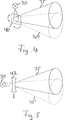
4 zeigt schematisch eine Beleuchtungseinrichtung gemäß einem Ausführungsbeispiel. 4 schematically shows a lighting device according to an embodiment.
5 zeigt schematisch eine Beleuchtungseinrichtung nach einem weiteren Ausführungsbeispiel. 5 schematically shows a lighting device according to another embodiment.
6 ist eine schematische Darstellung einer Vorrichtung gemäß einem Ausführungsbeispiel. 6 is a schematic representation of a device according to an embodiment.
7A und 7B zeigen schematisch eine Beleuchtungseinrichtung gemäß einem weiteren Ausführungsbeispiel. 7A and 7B schematically show a lighting device according to another embodiment.
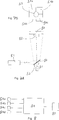
8 zeigt ein Blockdiagramm einer Auswerteeinrichtung für die Beleuchtungseinrichtung aus 7A und 7B. 8th shows a block diagram of an evaluation device for the lighting device 7A and 7B ,
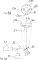
9A und 9B zeigen eine Beleuchtungseinrichtung gemäß einem weiteren Ausführungsbeispiel. 9A and 9B show a lighting device according to another embodiment.
10 zeigt eine Vorrichtung zur Oberflächenvermessung gemäß einem Ausführungsbeispiel der vorliegenden Erfindung. 10 shows a device for surface measurement according to an embodiment of the present invention.
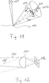
11 zeigt ein Schemadiagramm zur Veranschaulichung von Prinzipien mancher Ausführungsbeispiele der vorliegenden Erfindung. 11 shows a schematic diagram illustrating principles of some embodiments of the present invention.
12 zeigt einen Richtungsdetektor gemäß einem Ausführungsbeispiel der vorliegenden Erfindung. 12 shows a direction detector according to an embodiment of the present invention.
Nachfolgend werden Ausführungsbeispiele der Erfindung näher erläutert. Die Merkmale der verschiedenen Ausführungsbeispiele können miteinander kombiniert werden, sofern dies in der nachfolgenden Beschreibung nicht ausdrücklich ausgeschlossen wird. Auch wenn einzelne Ausführungsbeispiele im Hinblick auf spezifische Anwendung hin wie eine Positionsbestimmung in industriellen Einrichtungen oder eine Oberflächenvermessung in industriellen Einrichtungen beschrieben werden, ist die vorliegende Erfindung nicht auf diese Anwendung beschränkt.Hereinafter, embodiments of the invention are explained in detail. The features of the various embodiments may be combined with each other unless expressly excluded in the following description. Although individual embodiments are described in terms of specific application such as position determination in industrial facilities or surface measurement in industrial facilities, the present invention is not limited to this application.
1 ist eine schematische Darstellung einer Vorrichtung 1 zum Bestimmen einer Position eines Objekts nach einem Ausführungsbeispiel. Die Vorrichtung 1 ist im Kontext einer beispielhaften Anwendung dargestellt, bei der die Position einer Komponente eines Roboterarms 2, die mit einem Retroreflektor 25 versehen ist, ermittelt wird, kann aber ebenso in anderen Umgebungen und bei anderen Anwendungen eingesetzt werden. 1 is a schematic representation of a device 1 for determining a position of an object according to an embodiment. The device 1 is shown in the context of an example application where the position of a component of a robotic arm 2 that with a retro reflector 25 but can also be used in other environments and applications.
Die Vorrichtung 1 umfasst eine Lichtquelle 3, die mit einer Repetitionsrate eine Folge kurzer Lichtpulse erzeugt, eine Lichtlenkeinrichtung, die durch eine Mehrzahl von optischen Elementen 4–9 ausgebildet ist, ein Paar von Referenzsignaldetektoren 11, 12 mit einem ersten Referenzsignaldetektor 11 und einem zweiten Referenzsignaldetektor 12, eine Detektoranordnung mit mehreren optischen Detektoren 13, 14 und eine Auswerteschaltung 15. Die Lichtlenkeinrichtung empfängt die Folge von Lichtpulsen und lenkt die Folge von Lichtpulsen zu dem Paar von Referenzsignaldetektoren 11, 12 und in einen allgemein mit 28 bezeichneten Raumbereich, in dem die Position des an dem Roboterarm 2 angebrachten Retroreflektors 25 bestimmt werden soll. Aus Gründen der Einfachheit wird nachfolgend das von der Lichtlenkeinrichtung zu den Referenzsignaldetektoren 11, 12 und in den Raumbereich 28 gelenkte Licht ebenfalls als die Folge von Lichtpulsen bezeichnet, wobei ersichtlich ist, dass jeweils nur ein Anteil der von der Lichtquelle 2 erzeugten Lichtpulsintensität zu den Referenzsignaldetektoren 11, 12 bzw. in den Raumbereich 28 gelenkt wird. Die Folge von Lichtpulsen wird in dem Raumbereich von dem an dem Roboterarm 2 angeordneten Retroreflektor 25 reflektiert. Die reflektierte Folge von Lichtpulsen wird von den Detektoren 13, 14 erfasst. Die Auswerteschaltung 15 ermittelt aus den Signalen von den Referenzsignaldetektoren 11, 12, die an einem Referenzsignaleingang 16 empfangen werden, und aus den Signalen von den Detektoren 13, 14 eine Phasenlage von Signalkomponenten der an den Detektoren 13, 14 erfassten Lichtsignale, die in einer Beziehung zur Laufzeit der Lichtpulse in dem Raumbereich 28 und somit zum Abstand des Retroreflektors 25 von verschiedenen Elementen der Lichtlenkeinrichtung steht. Auf diese Weise kann die Position des Retroreflektors 25 ermittelt werden. Wie noch ausführlicher erörtert wird, beruht die Ermittlung der Phasenlage durch die Auswerteschaltung 15 auf Signalkomponenten der an den Detektoren 13, 14 erfassten Lichtsignale, die eine Frequenz aufweisen, die ein Vielfaches der Repetitionsrate ist.The device 1 includes a light source 3 , which generates a sequence of short light pulses at a repetition rate, a light-deflecting device that is guided by a plurality of optical elements 4 - 9 is formed, a pair of reference signal detectors 11 . 12 with a first reference signal detector 11 and a second reference signal detector 12 , a detector array with multiple optical detectors 13 . 14 and an evaluation circuit 15 , The light director receives the train of light pulses and directs the train of light pulses to the pair of reference signal detectors 11 . 12 and in a general with 28 designated space area in which the position of the robot arm 2 attached retroreflectors 25 should be determined. For the sake of simplicity, that from the light guide to the reference signal detectors will be described below 11 . 12 and in the room area 28 Directed light is also referred to as the sequence of light pulses, it being understood that only a portion of the light source 2 generated light pulse intensity to the reference signal detectors 11 . 12 or in the room area 28 is steered. The sequence of light pulses becomes in the space area of that on the robot arm 2 arranged retroreflector 25 reflected. The reflected sequence of light pulses is from the detectors 13 . 14 detected. The evaluation circuit 15 determined from the signals from the reference signal detectors 11 . 12 connected to a reference signal input 16 are received, and from the signals from the detectors 13 . 14 a phase relationship of signal components at the detectors 13 . 14 detected light signals related to the propagation time of the light pulses in the space area 28 and thus to the distance of the retroreflector 25 of different elements of the light-guiding device stands. In this way, the position of the retroreflector 25 be determined. As will be discussed in more detail, the determination of the phase angle is based on the evaluation circuit 15 on signal components at the detectors 13 . 14 detected light signals having a frequency which is a multiple of the repetition rate.
Die Detektoren 13, 14 und Referenzsignaldetektoren 11, 12 sind beispielsweise als Fotodetektoren ausgestaltet und erfassen die einfallende Lichtintensität.The detectors 13 . 14 and reference signal detectors 11 . 12 For example, they are designed as photodetectors and detect the incident light intensity.
Während in 1 aus Gründen der Übersichtlichkeit nur zwei Strahlteiler 5, 7, von denen aus Licht in den Raumbereich 28 gelenkt wird, und zwei diesen zugeordnete Detektoren 13, 14 dargestellt sind, kann Licht auch von mehr als zwei unterschiedlichen Positionen aus in den Raumbereich gelenkt werden, in dem die Position des Objekts bestimmt werden soll. Sollen alle drei räumlichen Koordinaten des Retroreflektors 25 bestimmt werden, kann die Folge von Lichtpulsen von wenigstens einer weiteren Einstrahlposition aus in den Raumbereich 28 gelenkt werden, die nicht auf einer Geraden angeordnet ist, die durch die Strahldurchtrittspunkte an den Strahlteilern 5 und 7 definiert ist.While in 1 for clarity, only two beam splitters 5 . 7 from which light in the room area 28 is directed, and two associated with these detectors 13 . 14 light can also be directed from more than two different positions into the spatial area in which the position of the object is to be determined. Shall all three spatial coordinates of the retroreflector 25 can be determined, the sequence of light pulses from at least one further Einstrahlposition from in the space area 28 which is not arranged on a straight line passing through the beam passing points at the beam splitters 5 and 7 is defined.
Die Funktionsweise der verschiedenen Komponenten der Vorrichtung 1 wird nachfolgend näher erläutert.The operation of the various components of the device 1 will be explained in more detail below.
Die Lichtquelle 3 erzeugt ein optisches Signal, das mit einer periodischen Funktion moduliert ist und das eine Grundfrequenz f0 sowie ausgeprägte Anteile von Oberwellen der Grundfrequenz f0, d. h. ausgeprägte Frequenzkomponenten mit Frequenzen aufweist, die Vielfache von f0 sind. Ein solches Signal wird beispielsweise durch einen Kurzpulslaser erzeugt, der eine Folge von Lichtpulsen in einem wohldefinierten zeitlichen Abstand T0 = 1/f0, d. h. mit einer Repetitionsrate f0, erzeugt, wobei die Dauer jedes Pulses kurz ist im Vergleich zum zeitlichen Abstand T0 zwischen aufeinanderfolgenden Pulsen.The light source 3 generates an optical signal which is modulated with a periodic function and which has a fundamental frequency f0 as well as pronounced portions of harmonics of the fundamental frequency f0, ie distinct frequency components with frequencies which are multiples of f0. Such a signal is generated, for example, by a short-pulse laser which generates a sequence of light pulses at a well-defined time interval T0 = 1 / f0, ie at a repetition rate f0, the duration of each pulse being short compared to the time interval T0 between successive pulses ,
Die Dauer jedes Lichtpulses kann im Vergleich zu dem Zeitabstand T0 zwischen aufeinanderfolgenden Lichtpulsen sehr klein sein, beispielsweise von der Größenordnung 1·10–5. Bei der Vorrichtung 3 können die Repetitionsrate f0 und die Zeitdauer jedes Pulses geeignet in Abhängigkeit von einer gewünschten Messgenauigkeit bei der Ortsbestimmung, einer anfänglichen Unsicherheit über die Position des Objekts, und der Signalkomponente des an den Detektoren 13, 14 detektierten Lichtsignals, für die eine Phasenlage bestimmt werden soll, oder in Abhängigkeit von weiteren Faktoren gewählt werden. Soll zur Bestimmung der Phasendifferenz die n-te Oberwelle von f0 verwendet werden, werden die Dauer jedes Lichtpulses und der Zeitabstand T0 zwischen aufeinanderfolgenden Lichtpulsen so gewählt, dass die von der Lichtquelle 3 ausgegebene Folge von Lichtsignalen noch ein ausreichendes spektrales Gewicht bei der Frequenz n·f0 aufweist. Als Pulsform kann eine Folge von Rechteckspulsen gewählt werden, können ebenso andere geeignete Pulsformen gewählt werden, beispielsweise das Quadrat eines hyperbolischen Secans oder eine Gaussfunktion.The duration of each light pulse may be very small compared to the time interval T0 between successive light pulses, for example of the order of 1 · 10 -5 . In the contraption 3 For example, the repetition rate f0 and the duration of each pulse may be properly determined in response to a desired measurement accuracy in location, an initial uncertainty about the position of the object, and the signal component of the detector 13 . 14 detected light signal for which a phase position to be determined, or be selected in dependence on other factors. If the n-th harmonic of f0 is to be used to determine the phase difference, the duration of each light pulse and the time interval T0 between successive light pulses are selected such that the light emitted by the light source 3 output sequence of light signals still has a sufficient spectral weight at the frequency n · f0. As a pulse shape, a sequence of rectangular pulses can be selected, other suitable pulse shapes can also be selected, for example the square of a hyperbolic secant or a Gaussian function.
Eine geeignete Folge von Lichtpulsen kann von verschiedenen Lasern erzeugt werden, die für die Erzeugung kurzer Lichtpulse eingerichtet sind. Insbesondere können optische Frequenzsynthesizer verwendet werden. Beispielsweise kann ein elektrisch gepumpter Diodenlaser, z. B. ein gütegeschalteter Laser, ein verstärkungsgeschalteter (gain switched) Laser, ein aktiv oder passiv modengekoppelter Laser oder ein Laser mit hybrider Modenkopplung, oder ein modengekoppelter oberflächenemittierender Laser mit vertikalem Resonator (Vertical-Cavity Surface Emitting Laser, VCSEL) als Lichtquelle 3 verwendet werden. Es kann auch ein optisch gepumpter Laser, beispielsweise ein passiv modengekoppelter oberflächenemittierender Laser mit externem vertikalen Resonator (Vertical External Cavity Surface Emitting Lasers, VECSEL) oder ein auf photonische-Kristallfasern basierender Laser (photonic-crystal-fiber laser) als Lichtquelle 3 verwendet werden. Beispielhafte Pulsdauern der Lichtquelle 3 liegen in einem Bereich von 100 fs und 100 ps. Beispielhafte Repetitionsraten liegen in einem Bereich von 50 MHz bis 50 GHz. Beispielhafte mittlere Leistungen liegen in einem Bereich von 1 mW bis 10 W. Beispielhafte Werte für den Pulsjitter liegen zwischen 10 fs und 1 ps Effektivwert (quadratischer Mittelwert).A suitable sequence of light pulses may be generated by different lasers adapted to generate short light pulses. In particular, optical frequency synthesizers can be used. For example, an electrically pumped diode laser, e.g. A Q-switched laser, a gain switched laser, an active or passive mode locked laser or a hybrid mode-locked laser, or a mode-locked vertical cavity surface emitting laser (VCSEL) as the light source 3 be used. It may also be an optically-pumped laser, such as a passive mode-locked external cavity surface emitting laser (VECSEL) or a photonic-crystal-fiber laser as a light source 3 be used. Exemplary pulse durations of the light source 3 are in the range of 100 fs and 100 ps. Exemplary repetition rates range from 50 MHz to 50 GHz. Exemplary average powers are in a range of 1 mW to 10 W. Exemplary values for the pulse jitter are between 10 fs and 1 ps effective value (root mean square).
Wie in 1 dargestellt, wird die von der Lichtquelle 3 ausgegebene Folge von Lichtpulsen von der Lichtlenkeinrichtung zu den Referenzsignaldetektoren 11, 12 und in den Raumbereich 28 gelenkt. Die Lichtlenkeinrichtung umfasst bei der Vorrichtung 1 mehrere Strahlteiler 4, 5 und 7, einen Spiegel 6 und Strahlaufweiter 8, 9, die den Strahlteilern 5 bzw. 7 zugeordnet sind. Der Strahlteiler 4 empfängt die Folge von Lichtpulsen von der Lichtquelle 3. Ein Teilstrahl 20 der Folge von Lichtpulsen wird von dem Strahlteiler 4 als Referenzsignal zu den Referenzsignaldetektoren 11, 12 gelenkt. Falls erforderlich, kann auch dem Strahlteiler 4 ein optisches Element zur Strahlaufteilung, insbesondere ein Strahlteiler, nachgeordnet sein um sicherzustellen, dass der Teilstrahl 20 sowohl auf den Referenzsignaldetektor 11 als auch auf den Referenzsignaldetektor 12 trifft. Ein weiterer Teilstrahl der Folge von Lichtpulsen wird von dem Strahlteiler 4 transmittiert und trifft auf den Strahlteiler 5. Der Strahlteiler 5 lenkt einen Teilstrahl 21 der Folge von Lichtpulsen über den Strahlaufweiter 8 in den Raumbereich 28, wobei der Strahlaufweiter 8 den Teilstrahl 21 zu einem Lichtkegel 22 aufweitet. Ein weiterer Teilstrahl wird von dem Strahlteiler 5 transmittiert und über den Spiegel 6 auf den Strahlteiler 7 gelenkt. Der Strahlteiler 7 lenkt einen Teilstrahl 26 der Folge von Lichtpulsen über den Strahlaufweiter 9 in den Raumbereich 28, wobei der Strahlaufweiter 9 den Teilstrahl 26 zu einem Lichtkegel 27 aufweitet. Bei dem dargestellten Ausführungsbeispiel ist die Aufweitung des Strahlaufweiters 8 und die Aufweitung des Strahlaufweiters 9 derart gewählt, dass der Lichtkegel 22 bzw. der Lichtkegel 27 nur einen Teil des Raumbereichs 28 beleuchten, in welchem eine Positionsbestimmung ermöglicht werden soll. Wie später unter Bezugnahme auf die 2–9 näher erläutert werden wird, sind Nachführeinrichtungen vorgesehen, welche beispielsweise in dem Ausführungsbeispiel der 1 die Lichtkegel 22 und 27 auf denjenigen Teil des Raumbereichs 28 lenken, in welchem sich der Retroreflektor 25 des Roboterarms 2 befindet.As in 1 represented by the light source 3 output sequence of light pulses from the light directing means to the reference signal detectors 11 . 12 and in the room area 28 directed. The light-directing device comprises in the device 1 several beam splitters 4 . 5 and 7 , a mirror 6 and beam expander 8th . 9 that the beam splitters 5 respectively. 7 assigned. The beam splitter 4 receives the train of light pulses from the light source 3 , A partial beam 20 the sequence of light pulses is from the beam splitter 4 as a reference signal to the reference signal detectors 11 . 12 directed. If necessary, can also be the beam splitter 4 an optical element for beam splitting, in particular a beam splitter, be arranged downstream to ensure that the partial beam 20 both to the reference signal detector 11 as well as the reference signal detector 12 meets. Another sub-beam of the sequence of light pulses is from the beam splitter 4 transmits and hits the beam splitter 5 , The beam splitter 5 directs a partial beam 21 the sequence of light pulses across the beam expander 8th in the room area 28 , wherein the beam expander 8th the partial beam 21 to a cone of light 22 expands. Another partial beam is from the beam splitter 5 transmitted and over the mirror 6 on the beam splitter 7 directed. The beam splitter 7 directs a partial beam 26 the sequence of light pulses across the beam expander 9 in the room area 28 , wherein the beam expander 9 the partial beam 26 to a cone of light 27 expands. In the illustrated embodiment, the expansion of the beam expander 8th and the expansion of the beam expander 9 chosen so that the light cone 22 or the light cone 27 only a part of the room area 28 illuminate in which a position determination is to be made possible. As later with reference to the 2 - 9 will be explained in more detail, tracking devices are provided which, for example, in the embodiment of 1 the light cones 22 and 27 on the part of the room area 28 guide in which the retro-reflector 25 of the robot arm 2 located.
Ein von dem Strahlteiler 7 transmittierter Anteil des von dem Spiegel 6 empfangenen Lichtstrahls kann über einen in 1 nicht dargestellten weiteren Strahlteiler in Richtung des Raumbereichs 28 gelenkt werden. Der Teil des Raumbereichs 28, in dem bei einer bestimmten Stellung der oben erwähnten Nachführeinrichtungen die Position des Objekts bestimmt werden kann, entspricht dem Überlappungsbereich der verschiedenen Lichtkegel 22, 27. Falls die Folge von Lichtpulsen von mehr als drei Positionen aus in Richtung des Raumbereichs gelenkt wird, in dem die Objektposition bestimmt werden soll, ist der Raumbereich, in dem eine Bestimmung der Objektposition möglich ist, die Vereinigung aller Überlappungsbereiche von wenigstens drei verschiedenen Lichtkegeln, die ausgehend von wenigstens drei Ausgangspunkten eingestrahlt werden, die nicht auf einer Geraden liegen.One from the beam splitter 7 transmitted portion of the mirror 6 received light beam can via a in 1 not shown further beam splitter in the direction of the spatial area 28 be steered. The part of the room area 28 , in which the position of the object can be determined at a certain position of the tracking devices mentioned above, corresponds to the overlapping area of the different light cones 22 . 27 , If the sequence of light pulses from more than three positions is directed towards the space area in which the object position is to be determined, the space area in which a determination of the object position is possible, the union of all overlapping areas of at least three different light cones are radiated from at least three starting points that are not on a straight line.
Die über den Strahlteiler 5 und den Lichtaufweiter 8 in dem Lichtkegel 22 in den Raumbereich 28 gelenkte Folge von Lichtpulsen trifft auf den Retroreflektor 25 und wird von diesem zurück in Richtung des Lichtaufweiters 8 reflektiert. Das von dem Retroreflektor 25 zurück in Richtung des Lichtaufweiters 8 reflektierte Licht bildet ein erstes Lichtsignal 23, das über den Lichtaufweiter 8 und den Strahlteiler 5 auf den Detektor 13 gelenkt wird. Die über den Strahlteiler 7 und den Lichtaufweiter 9 in dem Lichtkegel 26 in den Raumbereich 28 gelenkte Folge von Lichtpulsen trifft auf den Retroreflektor 25 und wird von diesem zurück in Richtung des Lichtaufweiters 9 reflektiert. Das von dem Retroreflektor 25 zurück in Richtung des Lichtaufweiters 9 reflektierte Licht bildet ein zweites Lichtsignal 24, das über den Lichtaufweiter 9 und den Strahlteiler 7 auf den Detektor 14 gelenkt wird. Wenn der Retroreflektor 25 im Lichtkegel weiterer Kombinationen von Strahlteiler, Lichtaufweiter und Detektor angeordnet ist, werden von dem Retroreflektor 25 aus entsprechend weitere Lichtsignale reflektiert, die über den Lichtaufweiter und Strahlteiler auf den entsprechenden Detektor gelenkt werden.The over the beam splitter 5 and the light expander 8th in the cone of light 22 in the room area 28 steered sequence of Light pulses hits the retroreflector 25 and from this back towards the light expander 8th reflected. That of the retroreflector 25 back in the direction of the light expander 8th reflected light forms a first light signal 23 that over the light expander 8th and the beam splitter 5 on the detector 13 is steered. The over the beam splitter 7 and the light expander 9 in the cone of light 26 in the room area 28 guided sequence of light pulses hits the retroreflector 25 and from this back towards the light expander 9 reflected. That of the retroreflector 25 back in the direction of the light expander 9 reflected light forms a second light signal 24 that over the light expander 9 and the beam splitter 7 on the detector 14 is steered. If the retroreflector 25 arranged in the light cone of other combinations of beam splitter, light expander and detector are of the retroreflector 25 from correspondingly reflected further light signals, which are directed via the light expander and beam splitter to the corresponding detector.
Die die Folge von Lichtpulsen in den Raumbereich 28 lenkende Lichtlenkeinrichtung und die Detektoren 13, 14 der Detektoranordnung sind so angeordnet, dass das in Richtung des Detektors 13 reflektierte Lichtsignal 23 in eine andere Richtung reflektiert wird als das in Richtung des Detektors 14 reflektierte Lichtsignal 24.The result of light pulses in the room area 28 directing light directing device and the detectors 13 . 14 the detector arrangement are arranged so that in the direction of the detector 13 reflected light signal 23 is reflected in a different direction than that in the direction of the detector 14 reflected light signal 24 ,
Der an dem Roboterarm 2 vorgesehene Retroreflektor 25 kann beispielsweise als Eckwürfelreflektor (Corner Cube Reflector, CCR), als Tripelprisma oder als Katzenaugenreflektor (Cat-Eye) bzw. als Kugellinse (Ball Lens) ausgestaltet sein. Beim Eckwürfelreflektor und dem Tripelprisma wird das Licht parallel zu den einfallenden Strahlrichtungen zurückreflektiert. Ein divergentes Strahlenbündel bleibt divergent. Beim Katzenaugenreflektor bzw. bei der Kugellinse können diese Retroreflektoren für eine bestimmte Distanz so optimiert werden, dass das reflektierte Strahlenbündel im Wesentlichen in sich selbst zurückreflektiert wird, wodurch am Detektor ein höherer Signalpegel vorliegt.The one on the robot arm 2 provided retroreflector 25 For example, it can be designed as a Corner Cube Reflector (CCR), as a triple prism or as a Cat Eye Reflector (Cat Eye) or as a Ball Lens (Ball Lens). In the corner cube reflector and the triple prism, the light is reflected back parallel to the incident beam directions. A divergent beam remains divergent. In the cat-eye reflector or in the ball lens, these retroreflectors can be optimized for a certain distance in such a way that the reflected beam is essentially reflected back into itself, as a result of which a higher signal level is present at the detector.
Anstelle eines Retroreflektors kann auch ein kleines streuendes Element verwendet werden, das sich in seinem Streuverhalten deutlich von seiner Umgebung unterscheidet, um Licht von dem relevanten Objektpunkt zu den Detektoren hin zu streuen. Damit am Detektor ein nutzbares Signal vorliegt, das vom Rauschen der streuenden Umgebung unterscheidbar ist, sollte das kleine Element Licht stark streuen.Instead of a retroreflector, it is also possible to use a small scattering element which differs significantly in its scattering behavior from its surroundings in order to scatter light from the relevant object point to the detectors. In order for the detector to have a usable signal that is distinguishable from the noise of the scattering environment, the small element should scatter light strongly.
Die Lichtsignale 23 und 24 werden von den Detektoren 13 bzw. 14 erfasst. Die Detektoren 13, 14 und Referenzsignaldetektoren 11, 12 sind als Photoempfänger ausgestaltet. Die Detektoren 13 und 14 erfassen dabei die Lichtleistung der auf sie einfallenden Folge von Lichtpulsen, die über den dem Detektor 13 bzw. 14 jeweils zugeordneten Strahlteiler 5 bzw. 7 zu dem Retroreflektor 25 und von diesem zurück zu dem Detektor 13 bzw. 14 propagiert. Die unterschiedliche optische Weglänge eines Lichtpulses, um einerseits zu einem der Referenzsignaldetektoren 11, 12 und andererseits nach einer Reflexion an dem Retroreflektor 25 zu einem der Detektoren 13 bzw. 14 zu gelangen, führt zu einer Zeitverschiebung τ1 bzw. τ2 zwischen der Ankunft ein- und desselben Lichtpulses an einem der Detektoren 13 bzw. 14 und an den Referenzsignaldetektoren 11, 12, die gleich dem Unterschied in optischer Weglänge der Lichtpfade geteilt durch die Lichtgeschwindigkeit c ist. Da typischerweise nur ein geringer Anteil des in den Raumbereich 28 gelenkten Lichts von dem Retroreflektor 25 reflektiert wird, ist das Signal an den Detektoren 13, 14 gegenüber dem Referenzsignal an den Referenzsignaldetektoren 11, 12 abgeschwächt.The light signals 23 and 24 be from the detectors 13 respectively. 14 detected. The detectors 13 . 14 and reference signal detectors 11 . 12 are designed as photoreceivers. The detectors 13 and 14 At the same time, they record the light output of the sequence of light pulses incident on them, that over the detector 13 respectively. 14 respectively assigned beam splitter 5 respectively. 7 to the retroreflector 25 and from this back to the detector 13 respectively. 14 propagated. The different optical path length of a light pulse, on the one hand to one of the reference signal detectors 11 . 12 and, on the other hand, after reflection on the retroreflector 25 to one of the detectors 13 respectively. 14 to arrive, leads to a time shift τ 1 or τ 2 between the arrival of one and the same light pulse at one of the detectors 13 respectively. 14 and at the reference signal detectors 11 . 12 which is equal to the difference in optical path length of the light paths divided by the speed of light c. Because typically only a small portion of the in the space area 28 steered light from the retroreflector 25 is the signal at the detectors 13 . 14 to the reference signal at the reference signal detectors 11 . 12 weakened.
Die Weglängendifferenz beinhaltet einerseits Strecken, die von der Geometrie der Vorrichtung, insbesondere den Abständen zwischen den Strahlteilern 5, 7 und dem Strahlteiler 4 sowie den Abständen zwischen den Strahlteilern 4, 5, 7 und den Detektoren 13, 14 bzw. den Referenzsignaldetektoren 11, 12, jeweils entlang des Strahlengangs, abhängen, und andererseits eine Komponente, die für das an dem Detektor 13 erfasste Lichtsignal von der optischen Weglänge zwischen dem Strahlteiler 5 oder dem virtuellen Ausgangspunkt des Lichtkegels 22, und dem Retroreflektor 25 und für das an dem Detektor 14 erfasste Signal von der optischen Weglänge zwischen dem Strahlteiler 7 oder dem virtuellen Ausgangspunkt des Lichtkegels 27, und dem Retroreflektor 25 abhängt. Da bei bekannter Geometrie der Vorrichtung 1 der von der Vorrichtungsgeometrie abhängige Anteil der Weglängendifferenz bekannt ist, kann durch Messung der Zeitverschiebung τ1 zwischen dem Lichtsignal 23 am Detektor 13 und dem Referenzsignal 20 an den Referenzsignaldetektoren 11, 12 die von dem Lichtpuls zurückgelegte optischen Weglänge zwischen dem Strahlteiler 5 und dem Retroreflektor 25 und somit der Abstand des Retroreflektors 25 von dem Strahldurchtrittspunkt des Strahlteilers 5 bzw. von dem virtuellen Ausgangspunkt des Lichtkegels 22 bestimmt werden. Ähnlich kann durch Messung der Zeitverschiebung τ2 zwischen dem Lichtsignal 24 am Detektor 14 und dem Referenzsignal 20 an den Referenzsignaldetektoren 11, 12 die von dem Lichtpuls zurückgelegte optischen Weglänge zwischen dem Strahlteiler 7 und dem Retroreflektor 25 und somit der Abstand des Retroreflektors 25 von dem Strahldurchtrittspunkt des Strahlteilers 7 bzw. von dem virtuellen Ausgangspunkt des Lichtkegels 27 bestimmt werden.On the one hand, the path length difference includes distances that depend on the geometry of the device, in particular the distances between the beam splitters 5 . 7 and the beam splitter 4 as well as the distances between the beam splitters 4 . 5 . 7 and the detectors 13 . 14 or the reference signal detectors 11 . 12 , each along the beam path, and on the other hand, a component that for the at the detector 13 detected light signal from the optical path length between the beam splitter 5 or the virtual starting point of the light cone 22 , and the retro reflector 25 and for that at the detector 14 detected signal from the optical path length between the beam splitter 7 or the virtual starting point of the light cone 27 , and the retro reflector 25 depends. Since with known geometry of the device 1 the dependent of the device geometry portion of the path length difference is known, by measuring the time shift τ 1 between the light signal 23 at the detector 13 and the reference signal 20 at the reference signal detectors 11 . 12 the optical path length traveled by the light pulse between the beam splitter 5 and the retro reflector 25 and thus the distance of the retroreflector 25 from the beam passing point of the beam splitter 5 or from the virtual starting point of the light cone 22 be determined. Similarly, by measuring the time shift τ 2 between the light signal 24 at the detector 14 and the reference signal 20 at the reference signal detectors 11 . 12 the optical path length traveled by the light pulse between the beam splitter 7 and the retro reflector 25 and thus the distance of the retroreflector 25 from the beam passing point of the beam splitter 7 or from the virtual starting point of the light cone 27 be determined.
Die Detektoren 13 und 14 sowie die Referenzsignaldetektoren 11, 12 sind mit der Auswerteschaltung 15 gekoppelt, die eine Phasendifferenz zwischen den Lichtsignalen 23, 24 und dem Referenzsignal 20 ermittelt. Die Auswerteschaltung 15 der Vorrichtung 1 ermittelt dann die Phasendifferenz zwischen dem Lichtsignal 23, 24 und dem Referenzsignal 20 für eine Signalkomponente, deren Frequenz im Wesentlichen ein Vielfaches der Repetitionsrate ist.The detectors 13 and 14 and the reference signal detectors 11 . 12 are with the evaluation circuit 15 coupled, which is a phase difference between the light signals 23 . 24 and the reference signal 20 determined. The evaluation circuit 15 the device 1 then determines the phase difference between the light signal 23 . 24 and the reference signal 20 for a signal component whose frequency is substantially a multiple of the repetition rate.
Auf Basis der ermittelten Phasendifferenzen, welche von den oben erwähnten Zeitverschiebungen abhängen, kann dann die Position des Retroreflektors 25 bestimmt werden. Based on the determined phase differences, which depend on the time shifts mentioned above, then the position of the retroreflector 25 be determined.
Es ist zu bemerken, dass die in 1 dargestellte Vorrichtung lediglich als Beispiel dient, und die nachfolgend erläuterten Nachführeinrichtungen generell in Fällen verwendet werden können, in welchen eine Position eines Objekts in zwei oder drei Raumrichtungen basierend auf von dem Objekt reflektierten Lichtstrahlen bestimmt werden soll.It should be noted that the in 1 The apparatus shown by way of example only serves as an example, and the tracking means explained below may be generally used in cases in which a position of an object in two or three spatial directions is to be determined based on light beams reflected from the object.
Nunmehr werden unter Bezugnahme auf die 2–9 Ausführungsbeispiele und Prinzipien der oben erwähnten Nachführeinrichtungen zum Lenken eines insbesondere aufgeweiteten Lichtstrahls in einen Teil eines interessierenden Raumbereichs, in welchem sich ein Retroreflektor, dessen Position zu bestimmen ist, befindet, erläutert. In den 2–9 werden gleiche Bezugszeichen verwendet, um gleiche oder ähnliche Elemente zu bezeichnen. 2 und 3 zeigen dabei Schemabilder, welche den Hintergrund für die Verwendung eines weniger aufgeweiteten Lichtstrahls erläutern.Now with reference to the 2 - 9 Embodiments and principles of the above-mentioned tracking device for directing a particular expanded light beam in a part of a space of interest, in which a retroreflector whose position is to be determined, is explained. In the 2 - 9 Like reference numerals are used to designate the same or similar elements. 2 and 3 show schema images that explain the background for the use of a less expanded light beam.
In den 2 und 3 ist ein Retroreflektor 33 schematisch als Kugel dargestellt, dessen Position innerhalb eines interessierenden Raumbereichs 31, welcher vereinfacht als Würfel dargestellt ist, bestimmt werden soll.In the 2 and 3 is a retro reflector 33 shown schematically as a sphere whose position within a space of interest 31 , which is simplified as a cube, to be determined.
Bei dem Beispiel von 2 erzeugt eine Lichtquelle 30 einen Lichtkegel 32, welcher derart aufgeweitet ist, dass er im Wesentlichen den gesamten Raumbereich 31 erfasst. Ein Raumwinkel entsprechend dem Lichtkegel 32 ist in 2 mit ΩS bezeichnet.In the example of 2 creates a light source 30 a cone of light 32 which is widened so as to cover substantially the entire space area 31 detected. A solid angle corresponding to the light cone 32 is in 2 denoted by Ω S.
Dementsprechend trifft nur ein relativ kleiner Teil des Lichtkegels 32 auf den Retroreflektor 33. Dieser Teil des Lichtkegels 32 ist in 2 mit dem Bezugszeichen 34 gekennzeichnet und entspricht einem Raumwinkel ΩR. Nur dieser Teil, welcher vom Retroreflektor 33 erfasst und reflektiert wird, kann zur Detektion genutzt werden.Accordingly, only a relatively small part of the cone of light hits 32 on the retroreflector 33 , This part of the light cone 32 is in 2 with the reference number 34 and corresponds to a solid angle Ω R. Only this part, which from the retro reflector 33 is detected and reflected, can be used for detection.
Da ΩR/ΩS im Fall von 2 relativ klein ist, wird also nur ein geringer Teil der Ausgangsleistung der Lichtquelle 30 tatsächlich genutzt. Dies kann zu einem relativ ungünstigen Signal-Rausch-Verhältnis führen und/oder leistungsstarke und somit relativ teure Lichtquellen 30 erfordern.Since Ω R / Ω S in the case of 2 is relatively small, so only a small part of the output power of the light source 30 actually used. This can lead to a relatively unfavorable signal-to-noise ratio and / or powerful and thus relatively expensive light sources 30 require.
Ein Wert für ΩR/ΩS für einen derartigen Fall kann beispielsweise aus dem Verhältnis der Querschnittsfläche des Retroreflektors 33 und der Querschnittsfläche des Raumbereichs 31 näherungsweise bestimmt werden. Ein typischer Wert ist beispielsweise 1 cm2 für die Querschnittsfläche des Retroreflektors 33 und einen Wert von 1 m2 für die Querschnittsfläche des Raumvolumens 31, d. h. des Messvolumens, was zu einem Verhältnis von 1·10–4 führt.A value for Ω R / Ω S for such a case may be, for example, the ratio of the cross-sectional area of the retroreflector 33 and the cross-sectional area of the space area 31 be approximated. A typical value is, for example, 1 cm 2 for the cross-sectional area of the retroreflector 33 and a value of 1 m 2 for the cross-sectional area of the volume of space 31 , ie the measuring volume, which leads to a ratio of 1 · 10 -4 .
In 3 wird im Vergleich hierzu ein Lichtkegel 35 verwendet, mit dem nur ein Teil des Raumbereichs 31 ausgeleuchtet wird. Ein Teil 36 des Lichtkegels 35 beleuchtet wiederum den Retroreflektor 33. Im Fall von 3 ist, wie unschwer zu erkennen, das Verhältnis ΩR/ΩS größer als im Fall von 2 oder, in anderen Worten, im Fall von 3 wird ein größerer Teil der Lichtintensität der Lichtquelle 30 für die tatsächliche Messung benutzt. Allerdings ist es in diesem Fall erforderlich, dass der Lichtkegel 35 einer Bewegung des Retroreflektors 33 folgt, so dass eine Messung im gesamten Raumbereich 31 erfolgen kann. Zur Nachführung können beispielsweise ein Spiegel oder auch andere optische Elemente dienen. Beispiele hierfür werden unter Bezugnahme auf 4 und 5 erläutert. Zu bemerken ist, dass, auch wenn in der oben stehenden Erläuterung und in den nachfolgenden Ausführungsbeispielen ein kegelförmig aufgeweiteter Lichtstrahl, d. h. ein divergenter Lichtstrahl, als Beispiel verwendet wird, die Erfindung nicht auf derartige Lichtstrahlen beschränkt ist. Bei anderen Ausführungsbeispielen können auch anders geformte Lichtstrahlen, beispielsweise kollimierte Lichtstrahlen, d. h. parallele Lichtstrahlen mit einem durch eine entsprechende Optik bestimmten Strahldurchmesser, oder konvergente, d. h. fokussierte Lichtstrahlen verwendet werden.In 3 becomes in comparison to this a light cone 35 used with only part of the space area 31 is illuminated. A part 36 of the light cone 35 in turn illuminates the retroreflector 33 , In case of 3 is, as can be easily recognized, the ratio Ω R / Ω S greater than in the case of 2 or, in other words, in the case of 3 becomes a larger part of the light intensity of the light source 30 used for the actual measurement. However, in this case it is necessary that the light cone 35 a movement of the retroreflector 33 follows, making a measurement throughout the room area 31 can be done. For tracking, for example, serve a mirror or other optical elements. Examples of this are with reference to 4 and 5 explained. It should be noted that although a conically expanded light beam, ie, a divergent light beam is used as an example in the above explanation and in the following embodiments, the invention is not limited to such light beams. In other embodiments, differently shaped light beams, for example collimated light beams, ie parallel light beams with a beam diameter determined by a corresponding optical system, or convergent, ie focused, light beams, can also be used.
Bei dem Ausführungsbeispiel der 4 wird ein kipp-/schwenkbarer Spiegel 40 verwendet, um die Richtung des Lichtkegels 35, welcher von der Lichtquelle 30 ausgesendet wird, zu verändern, beispielsweise zu dem gestrichelt dargestellten Lichtkegel 35'.In the embodiment of the 4 becomes a tilting / swiveling mirror 40 used to change the direction of the light cone 35 , which from the light source 30 is sent to change, for example, to the light cone shown in dashed lines 35 ' ,
Bei dem Ausführungsbeispiel von 5 wird statt des Spiegels 40 zur Einstellung der Richtung des Lichtkegels 35 ein lateral dezentrierbares abbildendes Element, in diesem Beispiel eine Linse 42, verwendet. Durch Verschieben der Linse 42 senkrecht zur Strahlrichtung wie durch einen Pfeil angedeutet kann ebenso die Richtung des Lichtkegels 35 verändert werden. Zu bemerken ist, dass ein derartiges System nicht auf ein einziges verschiebbares abbildendes Element begrenzt ist, sondern auch mehrere verschiebbare abbildende Elemente wie Linsen vorgesehen sein können. Auch ist statt einer Verschiebung senkrecht zur Strahlrichtung ein Kippen oder andere Bewegung derartiger abbildender Elemente denkbar. Auch eine Kombination eines lateral dezentrierbaren abbildenden Elements mit einem kipp-/schwenkbaren Spiegel ist möglich.In the embodiment of 5 will take the mirror 40 for adjusting the direction of the light cone 35 a laterally decenterable imaging element, in this example a lens 42 , used. By moving the lens 42 perpendicular to the beam direction as indicated by an arrow can also be the direction of the light cone 35 to be changed. It should be noted that such a system is not limited to a single displaceable imaging element, but also a plurality of displaceable imaging elements such as lenses may be provided. Also, instead of a displacement perpendicular to the beam direction, a tilting or other movement of such imaging elements is conceivable. A combination of a laterally decenterable imaging element with a tiltable / tiltable mirror is also possible.
Bei derartigen Systemen, in welchen ein Lichtkegel einer oder mehrerer Lichtquellen nur einen Teil eines Raumbereichs, innerhalb welchem eine Positionsbestimmung erfolgen soll, erfassen, ist es nötig, eine Information über die Position eines Retroreflektors oder eines anderen zu beleuchtenden Objekts zu erhalten, um den Lichtkegel entsprechend ausrichten zu können. Bei einem Ausführungsbeispiel wie demjenigen von 1 kann diese Bestimmung beispielsweise durch Messgeber in den Achsen des Roboters 2 erfolgen, durch welche eine Positionsbestimmung des Retroreflektors 25 möglich ist. Diese Positionsbestimmung ist generell ungenauer als die Positionsbestimmung, welche letztendlich durch die optische Messung erfolgt, reicht aber im Allgemeinen aus, um den Lichtkegel entsprechend auszurichten. Die Aufweitung des Lichtkegels kann dann entsprechend der Messgenauigkeit der Messgeber in dem Roboter gewählt werden. Falls keine derartigen Messgeber vorhanden sind, können auch Daten eines Steuerprogramms für die Steuerung der Bewegung des Roboters verwendet werden.In such systems, in which a light cone of one or more light sources only a part of a spatial area, within which To detect a position, it is necessary to obtain information about the position of a retroreflector or other object to be illuminated in order to align the beam accordingly. In an embodiment such as that of 1 This determination can be made, for example, by encoders in the axes of the robot 2 take place, by which a position determination of the retroreflector 25 is possible. This position determination is generally more inaccurate than the position determination that ultimately results from the optical measurement, but is generally sufficient to properly align the light cone. The widening of the light cone can then be selected according to the measuring accuracy of the sensors in the robot. If there are no such encoders, data from a control program can be used to control the movement of the robot.
Schließlich können, wenn einmal – beispielsweise durch Abrastern des Raumvolumens mit dem oder den Lichtkegeln – die Position mittels der optischen Messung bestimmt wurde, auch die Position der optischen Messung selbst zur Nachführung verwendet werden. Ergibt die optische Messung, dass sich der Retroreflektor zum Rand des entsprechenden Lichtkegels hinbewegt, wird der Lichtkegel entsprechend nachgeführt. Auch hierzu kann die Größe des Lichtkegels, d. h. die Aufweitung, geeignet gewählt werden, um eine sichere Nachführung zu gewährleisten, d. h. einen gewissen Abstand von Zentrum des Lichtkegels zum Rand des Lichtkegels, um die Bewegung innerhalb des Lichtkegels rechtzeitig erfassen zu können.Finally, once the position has been determined by means of the optical measurement, for example by scanning the volume of space with the light cone (s), the position of the optical measurement itself can also be used for tracking. If the optical measurement shows that the retroreflector moves toward the edge of the corresponding light cone, the light cone is tracked accordingly. Again, the size of the cone of light, d. H. the widening, suitably chosen to ensure a safe tracking, d. H. a certain distance from the center of the cone of light to the edge of the light cone in order to detect the movement within the light cone in time.
Eine weitere Möglichkeit besteht darin, neben der Phase des reflektierten Lichtes zur Positionsbestimmung wie oben beschrieben zudem die Amplitude des reflektierten Lichtes auszuwerten und die Nachführung derart vorzunehmen, dass die Amplitude maximiert wird bzw. dass die Amplitude einen vorgegebenen Mindestwert erreicht. Ein Ausführungsbeispiel einer entsprechenden Vorrichtung ist in 6 dargestellt.Another possibility is to evaluate the amplitude of the reflected light in addition to the phase of the reflected light for position determination as described above and to perform the tracking in such a way that the amplitude is maximized or that the amplitude reaches a predetermined minimum value. An embodiment of a corresponding device is shown in FIG 6 shown.
Das Ausführungsbeispiel der 6 kann als Erweiterung des Ausführungsbeispiels von 1 implementiert werden, kann jedoch auch unabhängig hiervon implementiert werden.The embodiment of 6 can as an extension of the embodiment of 1 but can be implemented independently.
Bei dem Ausführungsbeispiel von 6 erzeugt eine Lichtquelle 126, beispielsweise ein Kurzpulslaser wie bereits oben beschrieben, einen Lichtstrahl. Durch einen Strahlteiler 133 wird ein Teil des Lichtstrahls auf einen Referenzdetektor 124 gelenkt, dessen Funktion der Funktion der Referenzdetektoren 11, 12 der 1 entspricht. Ein übriger Teil des Lichtstrahls wird auf einen Spiegel 135 gelenkt, welcher mittels eines Spiegelantriebs 122 beweglich ist, um den Lichtstrahl auf einen Retroreflektor 121 zu lenken. Während in 6 nur ein einziger Spiegel dargestellt ist, können bei Ausführungsbeispielen zur dreidimensionalen Positionsbestimmung auch entsprechend drei Spiegel und entsprechend mehr Strahlteiler vorhanden sein, oder zur zweidimensionalen Positionsbestimmung zwei Spiegel und zwei Strahlteiler, um drei bzw. zwei Lichtstrahlen auf den Retroreflektor 121 zu lenken, wie dies bereits unter Bezugnahme auf 1 erläutert worden ist. Bei anderen Ausführungsbeispielen können zusätzliche Lichtquellen zur Erzeugung zusätzlicher Lichtstrahlen vorgesehen sein.In the embodiment of 6 creates a light source 126 For example, a short pulse laser as described above, a light beam. Through a beam splitter 133 becomes a part of the light beam on a reference detector 124 whose function is the function of the reference detectors 11 . 12 of the 1 equivalent. A remaining part of the light beam is onto a mirror 135 steered, which by means of a mirror drive 122 is movable to the light beam on a retroreflector 121 to steer. While in 6 only a single mirror is shown, in embodiments for three-dimensional position determination according to three mirrors and correspondingly more beam splitters may be present, or two-dimensional position determination two mirrors and two beam splitters to three or two light beams to the retroreflector 121 to direct, as already referring to 1 has been explained. In other embodiments, additional light sources may be provided for generating additional light rays.
Als Beispiel sind in 6 zwei Positionen a und b des Spiegels 135 dargestellt, entsprechend Positionen 121a und 121b des Retroreflektors. Zu bemerken ist, dass der Lichtstrahl vor oder nach dem Spiegel 135 durch eine (nicht dargestellte) Optik aufgeweitet werden kann, wie dies ebenfalls bereits erläutert worden ist.As an example, in 6 two positions a and b of the mirror 135 represented, according to positions 121 and 121b of the retroreflector. It should be noted that the light beam in front of or behind the mirror 135 can be expanded by a (not shown) optics, as has also already been explained.
Von dem Retroreflektor 121 reflektiertes Licht wird über den Spiegel 135 und einen Strahlteiler 134 zu einem Detektor 123 gelenkt. Ein Messverstärker und Mischer 125 verarbeitet die Signale der Detektoren 123 und 124 und leitet die jeweils verarbeiteten Signale zu einem Phasenmesser 127 weiter, welcher eine Phasendifferenz der Signale mischt, woraus wie bereits erläutert auf die Position des Retroreflektors 121 geschlossen werden kann. Der Mischer des Messverstärkers/Mischers 125 dient bei dem dargestellten Ausführungsbeispiel insbesondere dazu, das von dem Detektor 123 ausgegebene Signal, welches eine Frequenz aufweist, welche bei einem Kurzpulslaser der Frequenz des Kurzpulslasers entspricht, auf eine Zwischenfrequenz herunterzumischen.From the retroreflector 121 reflected light is transmitted through the mirror 135 and a beam splitter 134 to a detector 123 directed. A measuring amplifier and mixer 125 processes the signals of the detectors 123 and 124 and forwards the respective processed signals to a phase meter 127 Next, which mixes a phase difference of the signals, resulting from the position of the retroreflector as already explained 121 can be closed. The mixer of the measuring amplifier / mixer 125 serves in the illustrated embodiment in particular to that of the detector 123 output signal which has a frequency which corresponds to the frequency of the short pulse laser at a short pulse laser, down to an intermediate frequency.
Zudem wird das durch den Messverstärker und Mischer 5 verarbeitete Signal des Detektors 123 von einem Gleichrichter 128 gleichgerichtet und von einem Tiefpassfilter 129 geglättet. Das so erzeugte Signal wird von einem Analog-Digital-Wandler 130 in ein digitales Signal umgesetzt, dessen Größe ein Maß für die Amplitude des von dem Detektor 123 detektierten Signals ist. Dieses Digitalsystem wird eine Auswerteeinheit 131, beispielsweise einem Mikroprozessor oder einem Rechner, übergeben.In addition, this is done by the measuring amplifier and mixer 5 processed signal of the detector 123 from a rectifier 128 rectified and by a low-pass filter 129 smoothed. The signal thus generated is from an analog-to-digital converter 130 converted into a digital signal whose size is a measure of the amplitude of the detector 123 detected signal. This digital system becomes an evaluation unit 131 , For example, a microprocessor or a computer passed.
Die Auswerteeinheit 131 kann dabei die gleiche Auswerteeinheit sein, welche auch die von dem Phasenmesser 127 detektierte Phasendifferenz bestimmt oder auswertet.The evaluation unit 131 may be the same evaluation, which also of the phase meter 127 detected phase difference is determined or evaluated.
In Abhängigkeit von der so erfassten Signalamplitude an dem Detektor 123 steuert die Auswerteeinheit 131 dann über einen Digital-Analog-Wandler 132 den Spiegelantrieb 122 an.Depending on the thus detected signal amplitude at the detector 123 controls the evaluation unit 131 then via a digital-to-analog converter 132 the mirror drive 122 at.
Dabei wird beispielsweise zunächst, beispielsweise beim Starten der Vorrichtung, in einem Betriebsmodus der Spiegel 135 kontinuierlich über seinen gesamten Winkelbereich durchgefahren, beispielsweise zunächst in einer Achse, dabei das Messsignal detektiert und in einer Tabelle zusammen mit der jeweiligen Position, z. B. Winkelposition, des Spiegels 135 abgelegt. Nach diesem „Suchdurchlauf” wird die Position, d. h. der Winkel, des Spiegels 135 so eingestellt, dass er die Position einnimmt, bei der das Maximum der Amplitude erkannt wurde. Bei anderen Ausführungsbeispielen ist die anfängliche Position des Retroreflektors bekannt, und der „Suchdurchlauf” entfällt. In this case, for example, first, for example when starting the device, in an operating mode of the mirror 135 continuously traversed over its entire angular range, for example, first in one axis, while the measurement signal detected and in a table together with the respective position, eg. B. angular position, of the mirror 135 stored. After this "search run" becomes the position, ie the angle, of the mirror 135 adjusted so that it assumes the position at which the maximum of the amplitude was detected. In other embodiments, the initial position of the retroreflector is known and the "search pass" is eliminated.
Während des Betriebs wird dann in einem zweiten Betriebsmodus durch kontinuierliches oder intervallartiges Überwachen des von dem Analog-Digital-Wandler 130 ausgegebenen Signals die Position des Spiegels 135 derart nachgeführt, dass das Messsignal, d. h. die Amplitude des an dem Detektor 123 empfangenen Signals, maximiert wird und/oder einen vorgegebenen Schwellenwert erreicht.During operation, then, in a second mode of operation, monitoring the analog-to-digital converter continuously or intermittently 130 signal output the position of the mirror 135 tracked so that the measurement signal, ie the amplitude of the at the detector 123 received signal, is maximized and / or reaches a predetermined threshold.
Während bei dem Ausführungsbeispiel von 6 ein Signal nach dem Messverstärker/Mischer 125 ausgewertet wird, kann bei anderen Ausführungsbeispielen auch direkt das von dem Detektor 123 ausgegebene Signal ausgewertet werden und dessen Amplitude bestimmt werden.While in the embodiment of 6 a signal after the amplifier / mixer 125 is evaluated, in other embodiments, directly from the detector 123 output signal are evaluated and its amplitude can be determined.
Bei wieder anderen Ausführungsbeispielen werden zusätzliche Detektoren verwendet, um eine Bewegung des Retroreflektors zu erfassen und den Lichtkegel entsprechen nachzuführen. Beispiele hierfür werden nunmehr unter Bezugnahme auf 7–9 erläutert.In yet other embodiments, additional detectors are used to detect movement of the retroreflector and track the beam accordingly. Examples of this will now be with reference to 7 - 9 explained.
In 7 und 8 ist dabei ein Ausführungsbeispiel einer erfindungsgemäßen Nachführeinrichtung mit Detektoranordnung dargestellt. 7A zeigt eine Ansicht der Nachführeinrichtung, 7B zeigt eine Teilansicht einer verwendeten Retroreflektor/Detektoranordnung und 8 ein Blockschaltbild einer entsprechenden Auswerte/Steuereinrichtung. Bei dem Ausführungsbeispiel der 7A wird Licht, beispielsweise Laserlicht eines Kurzpulslasers, von einer Lichtquelle 51 erzeugt und über einen Spiegel 59 zu einem Retroreflektor 53 hingelenkt, wie bereits oben beschrieben. Die Lichtquelle 51 kann dabei sowohl die eigentliche Lichtquelle, z. B. einen Laser, als auch eine Optik zur kegelförmigen Aufweitung des erzeugten Lichtstrahls oder andere optische Elemente wie z. B. in 1 dargestellt umfassen.In 7 and 8th An exemplary embodiment of a tracking device according to the invention with a detector arrangement is shown. 7A shows a view of the tracking device, 7B shows a partial view of a retroreflector / detector arrangement used and 8th a block diagram of a corresponding evaluation / control device. In the embodiment of the 7A becomes light, for example laser light of a short pulse laser, from a light source 51 generated and through a mirror 59 to a retro reflector 53 steered, as already described above. The light source 51 can be both the actual light source, z. As a laser, as well as an optic for conically widening the generated light beam or other optical elements such. In 1 illustrated.
Der Spiegel 59 kann dabei durch einen Spiegelantrieb 57 bewegt werden, um die Richtung des von der Lichtquelle 51 erzeugten Lichtkegels zu ändern und insbesondere den Lichtkegel auf den Retroreflektor 53 zu lenken. Bei dem Retroreflektor 53 ist zudem eine Detektoranordnung 54 vorgesehen, welche bei dem dargestellten Ausführungsbeispiel die Form einer Quadrantendiode bzw. eines Quadrantendetektors aufweist. Diese Anordnung ist in 7B detaillierter gezeigt. Mittig ist der Retroreflektor 53 angeordnet, um ihn herum vier Quadranten 54a–54d des Quadrantendetektors 54, z. B. vier im Wesentlichen unabhängige Fotodioden.The mirror 59 can by doing a mirror drive 57 be moved to the direction of the light source 51 to change the light cone produced and in particular the light cone on the retroreflector 53 to steer. With the retroreflector 53 is also a detector arrangement 54 provided, which has the form of a quadrant diode or a quadrant detector in the illustrated embodiment. This arrangement is in 7B shown in more detail. In the middle is the retroreflector 53 arranged around it four quadrants 54a - 54d of the quadrant detector 54 , z. B. four substantially independent photodiodes.
Durch die vier Quadranten 54a–54d des Quadrantendetektors kann eine Relativbewegung des Lichtkegels zu dem Retroreflektor 53 erfasst werden, bevor der Retroreflektor 53 den Lichtkegel verlässt, und der Lichtkegel entsprechend nachgeführt werden. Eine derartige Relativbewegung kann beispielsweise durch eine Bewegung des Retroreflektors 53, welcher an einem Roboterarm wie in 1 dargestellt angebracht sein kann, hervorgerufen werden.Through the four quadrants 54a - 54d of the quadrant detector may be a relative movement of the light cone to the retroreflector 53 be detected before the retroreflector 53 leaves the cone of light, and the light cone be tracked accordingly. Such a relative movement, for example, by a movement of the retroreflector 53 which is attached to a robotic arm as in 1 shown may be caused.
Beispielsweise deutet eine Abschwächung des von dem Quadranten 54a detektierten Lichtes bei gleichzeitig konstantem Lichteinfall auf den Quadranten 54c darauf hin, dass sich der Lichtkegel relativ zu dem Retroreflektor 53 zu dem Quadranten 54c hinbewegt, hin, so dass der Lichtkegel entsprechend nachgeführt werden kann.For example, a weakening indicates that of the quadrant 54a detected light with simultaneous constant incidence of light on the quadrant 54c suggest that the light cone relative to the retroreflector 53 to the quadrant 54c moved back, so that the beam can be tracked accordingly.
Eine entsprechende Steuereinrichtung ist in 8 schematisch dargestellt. Hier empfängt eine Steuereinrichtung 58, welche beispielsweise in Form eines programmierbaren Logikchips oder auch als fest verdrahtete Hardware ausgeführt sein kann, Signale der Quadranten 54a–54d und ermittelt durch Verknüpfung dieser Signale wie oben beispielhaft erläutert eine Bewegungsrichtung des Lichtkegels relativ zu dem Retroreflektor 53. Basierend auf der ermittelten Bewegungsrichtung wird dann der Spiegelantrieb 57 angesteuert, um den Spiegel 59 zur Nachführung des Lichtkegels zu bewegen, um sicherzustellen, dass der Retroreflektor 53 stets vom Lichtkegel erfasst wird.A corresponding control device is in 8th shown schematically. Here receives a control device 58 , which may be implemented, for example, in the form of a programmable logic chip or as hard-wired hardware, quadrant signals 54a - 54d and determines by linking these signals as exemplified above, a direction of movement of the light cone relative to the retroreflector 53 , Based on the determined direction of movement then the mirror drive 57 driven to the mirror 59 to move the beam of light to make sure the retroreflector 53 is always detected by the light cone.
In dem Ausführungsbeispiel der 7 und 8 kann statt einer Quadrantendiode auch eine andere Mehrfachdetektoranwendung verwendet werden, wobei auch weniger als vier Einzeldetektoren (Quadranten), aber auch mehr als vier Einzeldetektoren vorgesehen sein können.In the embodiment of 7 and 8th It is also possible to use a different multiple detector application instead of one quadrant diode, and fewer than four individual detectors (quadrants), but also more than four individual detectors can be provided.
Ein weiteres Ausführungsbeispiel einer erfindungsgemäßen Nachführeinrichtung ist in 9 dargestellt. Dabei zeigt 9A eine schematische Ansicht der Nachführeinrichtung, und 9B zeigt eine Detailansicht eines Retroreflektors 53 mit darum angeordneten Leuchtdioden.Another embodiment of a tracking device according to the invention is in 9 shown. It shows 9A a schematic view of the tracking device, and 9B shows a detailed view of a retroreflector 53 with light emitting diodes arranged around it.
Wie bei dem Ausführungsbeispiel der 7 und 8 ist bei dem Ausführungsbeispiel von 9A eine Lichtquelle 51, ein Spiegel 59, ein Spiegelantrieb 57 sowie ein Retroreflektor 53 bereitgestellt. Die Funktion dieser Elemente entspricht der bereits unter Bezugnahme auf 7 und 8 erläuterten.As in the embodiment of 7 and 8th is in the embodiment of 9A a light source 51 , a mirror 59 , a mirror drive 57 as well as a retro reflector 53 provided. The function of these elements corresponds to that already with reference to 7 and 8th explained.
Bei dem Ausführungsbeispiel der 9 sind um den Retroreflektor 53 herum Lichtquellen, im dargestellten Beispiel vier Leuchtdioden 56a–56d, angeordnet. Die Anzahl vier ist lediglich als Beispiel zu verstehen, und es kann auch eine andere Anzahl von Leuchtdioden vorgesehen sein. Zudem können bei anderen Ausführungsbeispielen auch andere Lichtquellen als Leuchtdioden, beispielsweise Laserdioden, verwendet werden.In the embodiment of the 9 are around the retroreflector 53 around light sources, in the example shown four LEDs 56a - 56d arranged. The number four is to be understood as an example only and a different number of light-emitting diodes may be provided. In addition, in other embodiments, other light sources than light-emitting diodes, such as laser diodes, can be used.
Zudem weist das Ausführungsbeispiel der 9 einen Strahlteiler 52 auf, mit welchem von den Leuchtdioden 56a–56d ausgesendetes sowie von dem Retroreflektor 53 reflektiertes Licht über den Spiegel 59 und den Strahlteiler 52 zu einer Detektoranordnung 55 gelenkt wird. Die Detektoranordnung 55 ist ausgestaltet, das von den Leuchtdioden 56a–56d emittierte Licht zu detektieren. Bei dem Ausführungsbeispiel der 9 können die Leuchtdioden 56a–56d beispielsweise kontinuierlich emittierende Leuchtdioden sein. In einem derartigen Fall kann die Detektoranordnung 55 beispielsweise eine digitale Kamera umfassen, welche ein Bild entsprechend dem „Sichtbereich” des von der Lichtquelle 51 emittierten Lichtkegels entspricht, und durch Bildverarbeitung die Position der Leuchtdioden bestimmen und den Lichtkegel gegebenenfalls entsprechen nachführen.In addition, the embodiment of the 9 a beam splitter 52 on, with which of the LEDs 56a - 56d sent out as well as from the retroreflector 53 reflected light over the mirror 59 and the beam splitter 52 to a detector arrangement 55 is steered. The detector arrangement 55 is designed by the light-emitting diodes 56a - 56d to detect emitted light. In the embodiment of the 9 can the light emitting diodes 56a - 56d For example, be continuously emitting LEDs. In such a case, the detector arrangement 55 For example, a digital camera comprising an image corresponding to the "field of view" of the light source 51 emitted light cone corresponds, and determine by image processing, the position of the light emitting diodes and track the light cone as appropriate.
Ähnlich wie auf Basis der Quadranten des Quadrantendetektors in dem Ausführungsbeispiel der 7 und 8 kann so auch auf Basis des detektierten Lichts der Leuchtdiode 56a–56d eine Relativbewegung des Lichtkegels zu dem Retroreflektor 53 erkannt werden, bevor der Detektor 53 den Lichtkegel verlässt.Similar to the quadrant of the quadrant detector in the embodiment of FIG 7 and 8th can also be based on the detected light of the LED 56a - 56d a relative movement of the light cone to the retroreflector 53 be detected before the detector 53 leaves the cone of light.
Bei einem anderen Ausführungsbeispiel unterscheidet sich das Licht der Leuchtdioden 56a–56d vom Licht der Lichtquelle 51, beispielsweise indem es eine andere Wellenlänge und/oder eine andere Modulation aufweist. Zudem unterscheidet sich bei einem Ausführungsbeispiel das von den Leuchtdioden 56a–56d emittierte Licht voneinander, beispielsweise in dem für jede Leuchtdiode eine andere Modulation und/oder eine andere Lichtwellenlänge verwendet wird.In another embodiment, the light of the light-emitting diodes differs 56a - 56d from the light of the light source 51 For example, by having a different wavelength and / or a different modulation. In addition, in one embodiment, the different from the LEDs 56a - 56d emitted light from each other, for example, in that for each light emitting diode, a different modulation and / or a different wavelength of light is used.
Bei einem derartigen Ausführungsbeispiel kann das Licht der Leuchtdioden getrennt voneinander detektiert werden, beispielsweise auf Basis der oben erwähnten unterschiedlichen Modulation oder unterschiedlichen Wellenlänge. Zudem kann die Detektoranordnung 55 auch zur Detektion des von dem Retroreflektor 53 reflektierten Lichts und damit zur Positionsbestimmung wie bereits oben erläutert dienen. Hierfür kann jedoch auch eine separate Detektoranordnung vorgesehen sein.In such an embodiment, the light of the light-emitting diodes can be detected separately from one another, for example on the basis of the above-mentioned different modulation or different wavelength. In addition, the detector arrangement 55 also for the detection of the retroreflector 53 reflected light and thus for position determination as already explained above. However, a separate detector arrangement can also be provided for this purpose.
Wenn bei diesem Ausführungsbeispiel beispielsweise in der Detektoranordnung 55 das Licht der Leuchtdiode 56a nicht oder nur noch abgeschwächt detektiert wird und das Licht der Leuchtdiode 56c nach wie vor in voller Stärke detektiert wird, deutet dies auf eine Relativbewegung des Lichtkegels relativ zum Retroreflektor 53 zu der Leuchtdiode 56c von der Leuchtdiode 56a weg hin, und eine entsprechende (nicht dargestellte) Steuerung entsprechend der in 8 dargestellten Steuerung kann den Spiegelantrieb 57 dann ansteuern, um den Spiegel 59 zu bewegen, den Lichtkegel entsprechend nachzuführen.In this embodiment, for example, in the detector arrangement 55 the light of the LED 56a is not or only weakly detected and the light of the LED 56c is still detected in full strength, this indicates a relative movement of the cone of light relative to the retroreflector 53 to the light emitting diode 56c from the light emitting diode 56a away, and a corresponding (not shown) control according to the in 8th The controller shown can be the mirror drive 57 then head for the mirror 59 to move, nachzuführen the light cone accordingly.
Die Ausführungsbeispiele der 7–9 dienen lediglich als Beispiel, und auch andere Detektoranordnungen, beispielsweise Detektoren auf Basis einer Analyse einer von entsprechenden Digitalkameras aufgezeichneten Bildes des Raumbereichs, in welchem die Positionsbestimmung durchgeführt werden soll, vorgenommen werden.The embodiments of the 7 - 9 merely serve as an example, and also other detector arrangements, for example detectors based on an analysis of an image of the spatial area, recorded by corresponding digital cameras, in which the position determination is to be carried out.
Bei den Ausführungsbeispielen der 7–9, aber auch bei anderen Ausführungsbeispielen kann der Lichtkegel beispielsweise derart sein, dass er eine um 50–100% größere Fläche als die Fläche des jeweilig verwendeten Retroreflektors ausleuchtet. Es können jedoch auch weiter aufgeweitete Lichtkegel verwendet werden.In the embodiments of the 7 - 9 but also in other embodiments, the light cone may for example be such that it illuminates a 50-100% larger area than the surface of the respective retroreflector used. However, it is also possible to use further expanded light cones.
Wie bereits erwähnt können die Nachführeinrichtungen, welche unter Bezugnahme auf 2–9 erläutert wurden, beispielsweise in dem Ausführungsbeispiel der 1 eingesetzt werden, sie können jedoch auch bei anderen Vorrichtungen eingesetzt werden, bei welchen eine zweidimensionale oder dreidimensionale Position eines Objekts, beispielsweise eines mit einem Retroreflektor versehenen Objekts, durch Beleuchten des Objekts mit Strahlung, beispielsweise Laserstrahlung, und Analyse des reflektierten Lichtes bestimmt wird.As already mentioned, the tracking devices described with reference to 2 - 9 have been explained, for example, in the embodiment of 1 However, they can also be used in other devices in which a two-dimensional or three-dimensional position of an object, such as a retroreflected object, by illuminating the object with radiation, such as laser radiation, and analysis of the reflected light is determined.
Auf optische Weise kann nicht nur die Position eines Objekts in einem Raumbereich bestimmt werden, basierend auf ähnlichen Prinzipien kann auch eine dreidimensionale Oberfläche vermessen werden. Ein Ausführungsbeispiel einer derartigen Vorrichtung wird nunmehr unter Bezugnahme auf 10 erläutert.Not only can the position of an object in a space area be determined optically, but also a three-dimensional surface can be measured based on similar principles. An embodiment of such a device will now be described with reference to 10 explained.
10 ist eine schematische Darstellung einer Vorrichtung 51 zum Vermessen einer Oberfläche 52 nach einem Ausführungsbeispiel. 10 is a schematic representation of a device 51 for measuring a surface 52 according to an embodiment.
Die Vorrichtung 51 umfasst eine Lichtquelle 53, die mit einer Repetitionsrate eine Folge kurzer Lichtpulse erzeugt, eine Lichtlenkeinrichtung, die einen verstellbaren Umlenkspiegel 55 und eine zugehörige Verstelleinrichtung oder Aktorik 56 aufweist, eine Detektoranordnung 60 mit mehreren Fotodetektoren 61–64 und eine Auswerteschaltung 65. Von der Lichtquelle 53 wird die Folge von Lichtpulsen in einem Lichtstrahl auf den Umlenkspiegel 55 gestrahlt. Abhängig von der Stellung des Umlenkspiegels 55 wird die Folge von Lichtpulsen als Lichtstrahl 70 auf einen Oberflächenbereich 75 der Oberfläche 52 gelenkt. Eine charakteristische Ausdehnung des Oberflächenbereichs 75 ist dabei bestimmt durch den Durchmesser des Lichtstrahls 70, d. h. der Folge von Lichtpulsen, beim Auftreffen auf die Oberfläche 52. Wenn der Lichtstrahl 70 auf die Oberfläche 52 fokussiert wird, kann der Durchmesser des Oberflächenbereichs 75 im Idealfall im Wesentlichen beugungsbegrenzt sein.The device 51 includes a light source 53 , which generates a sequence of short light pulses at a repetition rate, a light-guiding device which an adjustable deflection mirror 55 and an associated adjusting device or actuator 56 comprising a detector arrangement 60 with several photodetectors 61 - 64 and an evaluation circuit 65 , From the light source 53 the sequence of light pulses in a beam of light on the deflection mirror 55 blasted. Depending on the position of the deflection mirror 55 becomes the sequence of light pulses as a light beam 70 on a surface area 75 the surface 52 directed. A characteristic extension of the surface area 75 is determined by the diameter of the light beam 70 , ie the sequence of light pulses, when hitting the surface 52 , When the light beam 70 on the surface 52 Focusing can be the diameter of the surface area 75 ideally be substantially diffraction-limited.
Die Folge von Lichtpulsen wird an dem Oberflächenbereich 75 gestreut. Die Fotodetektoren 61–64 der Detektoranordnung 10 empfangen Lichtsignale 71–74, die jeweils einen Anteil der von dem Oberflächenbereich 75 gestreuten Folge von Lichtpulsen beinhalten. Die Fotodetektoren 61–64 detektieren eine empfangene Lichtenergie bzw. Lichtintensität als Funktion der Zeit. Die Auswerteschaltung 65 ermittelt für die von den Fotodetektoren 61–64 erfassten Lichtsignale eine Phasenlage relativ zu der eingestrahlten Folge von Lichtpulsen. Die Phasenlage steht in einer Beziehung zur Laufzeit der Lichtpulse von dem Oberflächenbereich 75 zu den Fotodetektoren 61–64 und somit zum Abstand des Oberflächenbereichs 75 zu den Detektoren. Auf diese Weise kann die Position des Oberflächenbereichs 75 ermittelt werden. Die Ermittlung der Phasenlage durch die Auswerteschaltung 65 kann beispielsweise auf Signalkomponenten der an den Fotodetektoren 61–64 erfassten Lichtsignale beruhen, die eine Frequenz aufweisen, die ein Vielfaches der Repetitionsrate ist.The sequence of light pulses is at the surface area 75 scattered. The photodetectors 61 - 64 the detector assembly 10 receive light signals 71 - 74 , each containing a portion of the surface area 75 scattered sequence of light pulses include. The photodetectors 61 - 64 detect a received light energy or light intensity as a function of time. The evaluation circuit 65 detected for those of the photodetectors 61 - 64 detected light signals a phase position relative to the incident sequence of light pulses. The phase position is related to the transit time of the light pulses from the surface area 75 to the photodetectors 61 - 64 and thus to the distance of the surface area 75 to the detectors. In this way, the position of the surface area 75 be determined. The determination of the phase position by the evaluation circuit 65 can be used for example on signal components of the photodetectors 61 - 64 detected light signals having a frequency which is a multiple of the repetition rate.
Die Vorrichtung 51 umfasst weiterhin zwei Referenzsignaldetektoren 58, 59, auf die von einem Strahlteiler 54 die Folge von Lichtpulsen in einem Teilstrahl 69 als Referenzsignal gelenkt wird. Aus Gründen der Einfachheit wird hier davon gesprochen, dass sowohl in dem von dem Strahlteiler 54 zu dem Umlenkspiegel 55 transmittierten Lichtstrahl als auch in dem von dem Strahlteiler 54 zu den Referenzsignaldetektoren 58, 59 gelenkten Teilstrahl 69 die Folge von Lichtpulsen eingestrahlt wird, wobei es sich versteht, dass jeweils nur ein Anteil der Lichtintensität jedes Lichtpulses in dem Teilstrahl 69 zu den Referenzsignaldetektoren 58, 59 bzw. in dem Teilstrahl 70 auf die Oberfläche 52 gelenkt wird. Das Referenzsignal 69 wird von beiden Referenzsignaldetektoren 58, 59 erfasst und an einem Referenzsignaleingang 66 an die Auswerteschaltung 65 bereitgestellt. Gegebenenfalls kann ein Strahlaufweiter in dem Strahlengang des Teilstrahls 69 angeordnet sein, um sicherzustellen, dass der Teilstrahl 69 von beiden Referenzsignaldetektoren 58, 59 erfasst wird. Das von den Referenzsignaldetektoren 58, 59 jeweils bereitgestellte Referenzsignal von der Auswerteschaltung 65 wird verwendet, um die Phasenlagen der von dem Oberflächenbereich 75 gestreuten Folge von Lichtpulsen zu ermitteln.The device 51 further comprises two reference signal detectors 58 . 59 to which a beam splitter 54 the sequence of light pulses in a partial beam 69 is directed as a reference signal. For the sake of simplicity, it is said here that both in the beam splitter 54 to the deflection mirror 55 transmitted light beam as well as in the beam splitter 54 to the reference signal detectors 58 . 59 steered partial beam 69 the sequence of light pulses is irradiated, it being understood that in each case only a portion of the light intensity of each light pulse in the sub-beam 69 to the reference signal detectors 58 . 59 or in the sub-beam 70 on the surface 52 is steered. The reference signal 69 is from both reference signal detectors 58 . 59 detected and at a reference signal input 66 to the evaluation circuit 65 provided. Optionally, a beam expander in the beam path of the sub-beam 69 be arranged to ensure that the sub-beam 69 from both reference signal detectors 58 . 59 is detected. That of the reference signal detectors 58 . 59 respectively provided reference signal from the evaluation circuit 65 is used to control the phase angles of the surface area 75 scattered sequence of light pulses to determine.
Die Vorrichtung 51 umfasst weiterhin eine Recheneinheit 57, die mit der Auswerteschaltung 65 gekoppelt ist, um basierend auf den ermittelten Phasenlagen die Position des Oberflächenbereichs 75 zu bestimmen.The device 51 furthermore comprises a computing unit 57 that with the evaluation circuit 65 coupled to the position of the surface area based on the determined phase positions 75 to determine.
Unter der Bestimmung der Position des Oberflächenbereichs 75 wird hier die Ermittlung von drei Koordinaten eines Punktes des Oberflächenbereichs 75 verstanden. Da der Oberflächenbereich 75 im Idealfall eine kleine Abmessung hat, die durch den Durchmesser des eingestrahlten Lichtstrahls 70 bestimmt ist, wird vereinfachend auf die Position des Oberflächenbereichs Bezug genommen werden, auch wenn dieser selbst eine gewisse, geringe Ausdehnung aufweist.Under the determination of the position of the surface area 75 Here is the determination of three coordinates of a point of the surface area 75 Understood. As the surface area 75 ideally has a small dimension, determined by the diameter of the incident light beam 70 is determined, will be simplified to the position of the surface area reference, even if this itself has a certain small extent.
Um die Abmessung des Oberflächenbereichs 75 zu reduzieren und die laterale Auflösung bei der Vermessung der Oberfläche 52 zu erhöhen, ist eine einstellbare Fokussierungsoptik 67 in dem Strahlengang zwischen dem Strahlteiler 54 und dem Umlenkspiegel 55 vorgesehen. Die Fokussierungsoptik 67 wird von der Recheneinheit 57 derart angesteuert, dass der Lichtstrahl 70 auf der Oberfläche 52 fokussiert, im Idealfall beugungsbegrenzt fokussiert wird.To the dimension of the surface area 75 reduce and the lateral resolution in the measurement of the surface 52 is an adjustable focusing optics 67 in the beam path between the beam splitter 54 and the deflecting mirror 55 intended. The focusing optics 67 is from the arithmetic unit 57 controlled such that the light beam 70 on the surface 52 focused, ideally focused diffraction-limited.
Da bei der Vorrichtung 51 die Position des Oberflächenbereichs 75 basierend auf den von den Fotodetektoren 61–64 erfassten Lichtsignalen 71–74 und dem von den Referenzsignaldetektoren 58 und 59 erfassten Referenzsignal 69 ermittelt wird, muss zur Positionsbestimmung des Oberflächenbereichs 75 bei der Vorrichtung 51 die Winkelposition des Umlenkspiegels 55 nicht genau bekannt sein. Weiterhin wird durch Verwendung einer Detektoranordnung 60, bei der eine Anzahl von Fotodetektoren 61–64 verwendet wird, die größer als die Anzahl der zu bestimmenden Koordinaten des Oberflächenbereichs 75 ist, erreicht, dass die Positionsbestimmung robust erfolgen kann, selbst wenn die genaue Position des Umlenkspiegels 55 nicht bekannt ist.As with the device 51 the position of the surface area 75 based on that of the photodetectors 61 - 64 detected light signals 71 - 74 and that of the reference signal detectors 58 and 59 detected reference signal 69 must be determined to determine the position of the surface area 75 at the device 51 the angular position of the deflection mirror 55 not known exactly. Furthermore, by using a detector arrangement 60 in which a number of photodetectors 61 - 64 greater than the number of surface area coordinates to be determined 75 is achieved, that the position determination can be robust, even if the exact position of the deflection mirror 55 not known.
Die Recheneinheit 57 ist mit der Aktorik 56 des Umlenkspiegels 55 gekoppelt, um durch Steuern der Aktorik 56 die Position des Umlenkspiegels 55 einzustellen. Durch Verstellen des Umlenkspiegels 55 kann die Folge von Lichtpulsen als Lichtstrahl 28 auf einen anderen Oberflächenbereich 77 gelenkt werden, um dessen Position zu bestimmen. Um die Oberfläche 52 abzutasten, kann der Umlenkspiegel 55 kardanisch aufgehängt sein. Aufgrund der Robustheit der Positionsbestimmung bei der Vorrichtung 51 können jedoch auch andere, einfachere Ablenksysteme verwendet werden, beispielsweise eine Paar von um zwei zueinander orthogonale Achsen verkippbare oder drehbare Spiegel. Anstelle von Umlenkspiegeln können auch andere geeignete optische Elemente verwendet werden, um die Oberfläche abzutasten, beispielsweise ein Umlenkprisma oder dergleichen.The arithmetic unit 57 is with the actuators 56 the deflecting mirror 55 coupled to by controlling the actuators 56 the position of the deflecting mirror 55 adjust. By adjusting the deflecting mirror 55 can be the result of light pulses as a light beam 28 on a different surface area 77 be steered to determine its position. To the surface 52 can scan, the deflection mirror 55 to be gimballed. Due to the robustness of the position determination in the device 51 However, other, simpler deflection systems may be used, for example a pair of mirrors tiltable about two mutually orthogonal axes. Instead of deflecting mirrors, other suitable optical elements may be used to scan the surface, for example a deflecting prism or the like.
Da die Positionen der verschiedenen Oberflächenbereiche sequentiell bestimmt werden, wobei die Positionsbestimmung für jeden der Oberflächenbereiche auf dieselbe Weise erfolgt, wird nachfolgend nur die Positionsbestimmung für einen Oberflächenbereich näher beschrieben. Zum Vermessen der Oberfläche werden die Positionen mehrerer Oberflächenbereiche jeweils auf die beschriebene Weise nacheinander ermittelt.Since the positions of the various surface areas are sequentially determined, with the position determination being made for each of the surface areas in the same manner, only the position determination for a surface area will be described below. For measuring the surface, the positions of several surface areas are determined one after the other in the manner described.
Die Lichtquelle 53 der Vorrichtung 51 erzeugt beispielsweise ein optisches Signal, dessen Intensität mit einer periodischen Funktion moduliert ist, wobei die Modulation eine Grundfrequenz f0 sowie ausgeprägte Anteile von Oberwellen der Grundfrequenz f0, d. h. ausgeprägte Frequenzkomponenten mit Frequenzen aufweist, die Vielfache von f0 sind. Ein solches Signal wird beispielsweise durch einen Kurzpulslaser erzeugt, der eine Folge von Lichtpulsen in einem wohldefinierten zeitlichen Abstand T0 = 1/f0, d. h. mit einer Repetitionsrate f0, erzeugt, wobei die Dauer jedes Pulses kurz ist im Vergleich zum zeitlichen Abstand T0 zwischen aufeinanderfolgenden Pulsen.The light source 53 the device 51 generates, for example, an optical signal whose intensity is modulated with a periodic function, the modulation having a fundamental frequency f0 as well as pronounced portions of harmonics of the fundamental frequency f0, ie distinct frequency components with frequencies which are multiples of f0. Such a signal is generated, for example, by a short-pulse laser which generates a sequence of light pulses at a well-defined time interval T0 = 1 / f0, ie at a repetition rate f0, the duration of each pulse being short compared to the time interval T0 between successive pulses ,
Die Dauer jedes Lichtpulses kann im Vergleich zu dem Zeitabstand T0 zwischen aufeinanderfolgenden Lichtpulsen sehr klein sein, beispielsweise von der Größenordnung 1·10–5. Bei der Lichtquelle 53 können die Repetitionsrate f0 und die Zeitdauer jedes Pulses geeignet in Abhängigkeit von einer gewünschten Messgenauigkeit bei der Positionsbestimmung, von einer anfänglichen Unsicherheit über die Position des Oberflächenbereichs, von der Frequenz der Signalkomponente des an den Fotodetektoren 61–64 detektierten Lichtsignals, für die die Phasendifferenz bestimmt wird, oder in Abhängigkeit von weiteren Faktoren gewählt werden. Soll zur Bestimmung der Phasendifferenz die n-te Oberwelle von f0 verwendet werden, werden die Dauer jedes Lichtpulses und der Zeitabstand T0 zwischen aufeinanderfolgenden Lichtpulsen so gewählt, dass die von der Lichtquelle 53 ausgegebene Folge von Lichtpulsen noch ein ausreichendes spektrales Gewicht bei der Frequenz n·f0 aufweist. Die Pulse können eine Folge von Rechteckspulsen sein, aber es können ebenso andere geeignete Pulsformen gewählt werden, beispielsweise das Quadrat eines hyperbolischen Secans oder eine Gaussfunktion.The duration of each light pulse may be very small compared to the time interval T0 between successive light pulses, for example of the order of 1 · 10 -5 . At the light source 53 For example, the repetition rate f0 and the duration of each pulse may suitably depend on a desired measurement accuracy in the position determination, an initial uncertainty about the position of the surface area, the frequency of the signal component of the photodetectors 61 - 64 detected light signal for which the phase difference is determined, or be selected depending on other factors. If the n-th harmonic of f0 is to be used to determine the phase difference, the duration of each light pulse and the time interval T0 between successive light pulses are selected such that the light emitted by the light source 53 output sequence of light pulses still has a sufficient spectral weight at the frequency n · f0. The pulses may be a series of square pulses, but other suitable pulse shapes may be chosen, such as the square of a hyperbolic secant or a Gaussian function.
Eine geeignete Folge von Lichtpulsen kann von verschiedenen Lasern erzeugt werden, die für die Erzeugung kurzer Lichtpulse eingerichtet sind. Insbesondere können optische Frequenzsynthesizer verwendet werden. Beispielsweise kann ein elektrisch gepumpter Diodenlaser, z. B. ein gütegeschalteter Laser, ein verstärkungsgeschalteter (gain switched) Laser, ein aktiv oder passiv modengekoppelter Laser oder ein Laser mit hybrider Modenkopplung, oder ein modengekoppelter oberflächenemittierender Laser mit vertikalem Resonator (Vertical-Cavity Surface Emitting Laser, VCSEL) als Lichtquelle 53 verwendet werden. Es kann auch ein optisch gepumpter Laser, beispielsweise ein passiv modengekoppelter oberflächenemittierender Laser mit externem vertikalen Resonator (Vertical External Cavity Surface Emitting Lasers, VECSEL) oder ein auf photonische-Kristallfasern basierender Laser (photonic-crystal-fiber laser) als Lichtquelle 53 verwendet werden. Beispielhafte Pulsdauern der Lichtquelle 53 liegen in einem Bereich von 100 fs und 100 ps. Beispielhafte Repetitionsraten liegen in einem Bereich von 50 MHz bis 50 GHz. Beispielhafte mittlere Leistungen liegen in einem Bereich von 1 mW bis 10 W. Beispielhafte Werte für den Pulsjitter liegen zwischen 10 fs und 1 ps Effektivwert (quadratischer Mittelwert).A suitable sequence of light pulses may be generated by different lasers adapted to generate short light pulses. In particular, optical frequency synthesizers can be used. For example, an electrically pumped diode laser, e.g. A Q-switched laser, a gain switched laser, an active or passive mode locked laser or a hybrid mode-locked laser, or a mode-locked vertical cavity surface emitting laser (VCSEL) as the light source 53 be used. It may also be an optically-pumped laser, such as a passive mode-locked external cavity surface emitting laser (VECSEL) or a photonic-crystal-fiber laser as a light source 53 be used. Exemplary pulse durations of the light source 53 are in the range of 100 fs and 100 ps. Exemplary repetition rates range from 50 MHz to 50 GHz. Exemplary average powers are in a range of 1 mW to 10 W. Exemplary values for the pulse jitter are between 10 fs and 1 ps effective value (root mean square).
Wie in 10 dargestellt, wird ein Teilstrahl der von der Lichtquelle 53 ausgegebenen Folge von Lichtpulsen über den Strahlteiler 54 als Referenzsignal 69 zu den Referenzsignaldetektoren 58, 59 gelenkt. Falls erforderlich, kann im Strahlengang von dem Strahlteiler 54 zu den Referenzsignaldetektoren 58, 59 ein optisches Element zur Strahlaufteilung, insbesondere ein Strahlteiler vorgesehen sein um sicherzustellen, dass der Teilstrahl 69 sowohl auf den Referenzsignaldetektor 58 als auch auf den Referenzsignaldetektor 59 trifft. Ein weiterer Teilstrahl 70 wird über den Umlenkspiegel 55 auf den Oberflächenbereich 75 der Oberfläche 52 gelenkt. Hier wird angenommen, dass der Oberflächenbereich, auf den die Folge von Lichtpulsen eingestrahlt wird, lichtstreuende Eigenschaften aufweist. Die Folge von Lichtpulsen wird von dem Oberflächenbereich 75 in eine Vielzahl von Raumrichtungen gestreut. Das Streulicht beinhaltet auch die Folge von Lichtpulsen, die als Lichtsignale 71–74 in Richtung der Fotodetektoren 61–64 gestreut wird. Die Fotodetektoren 61–64 der Detektoranordnung 10 sind derart angeordnet, dass keiner der Fotodetektoren auf einer Geraden liegt, die durch einen Oberflächenbereich 75, 77, dessen Position zu bestimmen ist, und einen weiteren der Fotodetektoren geht. Bei der dargestellten Anordnung, bei der die vier Fotodetektoren 61–64 im Wesentlichen in einer Ebene derart angeordnet sind, dass nie mehr als zwei der Fotodetektoren 61–64 auf einer beliebig gewählten Geraden angeordnet sind, kann dies einfach erreicht werden, beispielsweise indem die Detektoranordnung 60 beabstandet von der Oberfläche 52 und in einem von 0° verschiedenen Winkel zu allen Verbindungsvektoren zwischen Oberflächenpunkten und Detektoranordnung 60 angeordnet wird. Aus den Phasenlagen der an den verschiedenen Fotodetektoren 61–64 erfassten Signalen kann in diesem Fall die Position des Oberflächenbereichs 75 bestimmt werden, da eine ausreichend hohe Anzahl von voneinander unabhängigen Phasenlagen ermittelbar ist.As in 10 is shown, a partial beam of the light source 53 output sequence of light pulses via the beam splitter 54 as a reference signal 69 to the reference signal detectors 58 . 59 directed. If necessary, in the beam path of the beam splitter 54 to the reference signal detectors 58 . 59 an optical element for beam splitting, in particular a beam splitter may be provided to ensure that the sub-beam 69 both to the reference signal detector 58 as well as the reference signal detector 59 meets. Another partial beam 70 is over the deflecting mirror 55 on the surface area 75 the surface 52 directed. Here, it is assumed that the surface area to which the train of light pulses is irradiated has light-scattering properties. The sequence of light pulses is from the surface area 75 scattered in a variety of spatial directions. The scattered light also includes the sequence of light pulses that act as light signals 71 - 74 in the direction of the photodetectors 61 - 64 is scattered. The photodetectors 61 - 64 the detector assembly 10 are arranged such that none of the photodetectors lie on a straight line passing through a surface area 75 . 77 , whose position is to be determined, and another of the photodetectors goes. In the illustrated arrangement, in which the four photodetectors 61 - 64 are arranged substantially in a plane such that never more than two of the photodetectors 61 - 64 are arranged on an arbitrarily chosen straight line, this can be easily achieved, for example by the detector array 60 spaced from the surface 52 and at an angle different from 0 ° to all connection vectors between surface points and detector array 60 is arranged. From the phasing of the various photodetectors 61 - 64 detected signals in this case, the position of the surface area 75 be determined, since a sufficiently high number of independent phase positions can be determined.
Die Lichtsignale 71–74 werden von den Fotodetektoren 61–64 erfasst. Aufgrund der mit wohldefinierter Repetitionsrate erzeugten Lichtpulse kann der Signalanteil, der von Streuung der Folge von Lichtpulsen an dem Oberflächenbereich 75 herrührt, bei der Signalverarbeitung durch die Auswerteschaltung 65 durch geeignete Filterung bestimmt werden, so dass im Folgenden Signalanteile, die nicht durch das von dem Oberflächenbereich 75 in Richtung der Fotodetektoren 61–64 gestreute Licht verursacht werden, nicht weiter erörtert werden.The light signals 71 - 74 be from the photodetectors 61 - 64 detected. Due to the light pulses generated at a well-defined repetition rate, the signal component resulting from scattering of the sequence of light pulses at the surface region 75 due to the signal processing by the evaluation circuit 65 be determined by suitable filtering, so that in the following signal components, not by that of the surface area 75 in the direction of the photodetectors 61 - 64 scattered light are caused, not further discussed.
Sowohl die Fotodetektoren 61–64 als auch die ebenfalls als Fotodetektoren ausgestalteten Referenzsignaldetektoren 58, 59 erfassen eine auf sie einfallende Lichtenergie als Funktion der Zeit. Die unterschiedliche optische Weglänge eines Lichtpulses, um einerseits zu einem der Referenzsignaldetektoren 58, 59 und andererseits nach einer Streuung an dem Oberflächenbereich 75 zu einem der Fotodetektoren 61–64 zu gelangen, führt jeweils zu einer Zeitverschiebung τ1, τ2, τ3 bzw. τ4 zwischen der Ankunft ein- und desselben Lichtpulses an einem der Detektoren 61–64 und an den Referenzsignaldetektoren 58, 59, die gleich dem Unterschied in optischer Weglänge der Strahlengänge geteilt durch die Lichtgeschwindigkeit c ist. Da typischerweise nur ein geringer Anteil des auf die Oberfläche 52 eingestrahlten Lichts 70 von dem Oberflächenbereich 75 in Richtung eines der Fotodetektoren 61–64 gestreut wird, ist das Signal an den Fotodetektoren 61–64 gegenüber dem Referenzsignal an den Referenzsignaldetektoren 58, 59 abgeschwächt.Both the photodetectors 61 - 64 as well as the also designed as photodetectors reference signal detectors 58 . 59 capture a light energy incident on them as a function of time. The different optical path length of a light pulse, on the one hand to one of the reference signal detectors 58 . 59 and, on the other hand, after scattering at the surface area 75 to one of the photodetectors 61 - 64 to arrive, leads in each case to a time shift τ 1 , τ 2 , τ 3 and τ 4 between the arrival of one and the same light pulse at one of the detectors 61 - 64 and at the reference signal detectors 58 . 59 which is equal to the difference in optical path length of the optical paths divided by the speed of light c. Because typically only a small proportion of the on the surface 52 irradiated light 70 from the surface area 75 in the direction of one of the photodetectors 61 - 64 is scattered, the signal is at the photodetectors 61 - 64 to the reference signal at the reference signal detectors 58 . 59 weakened.
Die Weglängendifferenz ist für jeden der Fotodetektoren 61–64 gegeben durch die Differenz zwischen der optischen Weglänge von dem Strahlteiler 54 über den Umlenkspiegel 55 zu dem Oberflächenbereich 75 und weiter zu dem entsprechenden Fotodetektor 61–64 und der optischen Weglänge von dem Strahlteiler 54 zu den Referenzsignaldetektoren 58, 59. Dabei hängt der erstgenannte Weg von dem Strahlteiler 54 über den Umlenkspiegel 55 zu dem Oberflächenbereich 75 und weiter zu dem entsprechenden Fotodetektor 61–64 von der zu bestimmenden Position des Oberflächenbereichs 75 ab, während der Abstand von dem Strahlteiler 54 zu den Referenzsignaldetektoren 58, 59 durch die Vorrichtungsgeometrie bestimmt ist und als bekannt vorausgesetzt wird. Durch Messung der Zeitverschiebungen τ1, τ2, τ3 bzw. τ4 zwischen den an den Fotodetektoren 61–64 erfassten Lichtsignalen 71–74 und dem Referenzsignal 69, das durch die Referenzsignaldetektoren 58, 59 erfasst wird, kann die von dem Lichtpuls zurückgelegte optische Weglänge zwischen dem Strahlteiler 54 und jedem der Fotodetektoren 61–64 bestimmt werden.The path length difference is for each of the photodetectors 61 - 64 given by the difference between the optical path length from the beam splitter 54 over the deflection mirror 55 to the surface area 75 and on to the corresponding photodetector 61 - 64 and the optical path length from the beam splitter 54 to the reference signal detectors 58 . 59 , In this case, the first-mentioned path depends on the beam splitter 54 over the deflection mirror 55 to the surface area 75 and on to the corresponding photodetector 61 - 64 from the position of the surface area to be determined 75 while the distance from the beam splitter 54 to the reference signal detectors 58 . 59 is determined by the device geometry and is assumed to be known. By measuring the time displacements τ 1 , τ 2 , τ 3 and τ 4 between those at the photodetectors 61 - 64 detected light signals 71 - 74 and the reference signal 69 that through the reference signal detectors 58 . 59 is detected, the distance traveled by the light optical path between the beam splitter 54 and each of the photodetectors 61 - 64 be determined.
Die Fotodetektoren 61–64 sowie die Referenzsignaldetektoren 58, 59 sind mit der Auswerteschaltung 65 gekoppelt, die eine Phasendifferenz zwischen den Lichtsignalen 71–74 und dem Referenzsignal 69 ermittelt.The photodetectors 61 - 64 and the reference signal detectors 58 . 59 are with the evaluation circuit 65 coupled, which is a phase difference between the light signals 71 - 74 and the reference signal 69 determined.
Die Auswerteschaltung 65 bestimmt dann aus den Phasendifferenzen die Position des jeweils vermessenen Abschnitts der Oberfläche.The evaluation circuit 65 then determines the position of each measured portion of the surface from the phase differences.
Um möglichst viel des von der Oberfläche gestreuten Lichtes aufzusammeln, kann vor den Detektoren 61–64 jeweils eine Sammellinse oder eine andere Sammeloptik angebracht sein. Um zu vermeiden, dass durch diese Fokussierung beispielsweise bei schrägem Lichteinfall ein Fokusspot diese Sektorfläche verlässt und somit keine Detektion mehr möglich ist, kann die Detektoranordnung 60 bei dem Ausführungsbeispiel von 10 durch einen Detektorantrieb 90 entsprechend geneigt werden. Bei einem anderen Ausführungsbeispiel ist für jeden einzelnen Detektor 61–64 ein Detektorantrieb vorgesehen, so dass die Detektoren individuell geneigt werden können. Der Detektorantrieb 90 kann beispielsweise einen sogenannten Voice Coil Motor oder Voice Coil Aktor enthalten. Derartige Aktoren werden auch als Tauchspulen bezeichnet und weisen insbesondere einen kleinen Bauraum auf. Es können jedoch auch andere Aktoren bzw. Motoren als Detektorantrieb verwendet werden.In order to collect as much as possible of the light scattered by the surface, in front of the detectors 61 - 64 be mounted in each case a converging lens or other collection optics. In order to avoid that a focusing spot leaves this sector area as a result of this focusing, for example in the case of oblique incidence of light, and thus detection is no longer possible, the detector arrangement can 60 in the embodiment of 10 through a detector drive 90 be inclined accordingly. In another embodiment, for each individual detector 61 - 64 a detector drive provided so that the detectors can be tilted individually. The detector drive 90 may for example contain a so-called voice coil motor or voice coil actuator. Such actuators are also referred to as plunger coils and have in particular a small space. However, other actuators or motors can be used as a detector drive.
Falls durch die Neigung eine wesentliche Positionsverschiebung einzelner Detektoren hervorgerufen wird, beispielsweise, wenn die gesamte Detektoranordnung geneigt wird, kann diese Neigung von der Auswerteschaltung 65 zusätzlich berücksichtigt werden.If the tendency causes a significant positional shift of individual detectors, for example, if the entire detector array is tilted, this inclination of the evaluation circuit 65 be taken into account additionally.
Um eine Richtung der einfallenden Lichtstrahlen zu bestimmen, ist bei dem Ausführungsbeispiel von 10 ein weiterer Detektor 91 vorgesehen, welcher eine Richtung des Lichteinfalls bestimmt und auf Basis dessen der Detektorantrieb 90 oder einzelne Detektorantriebe der einzelnen Detektoren entsprechend angesteuert werden.In order to determine a direction of the incident light rays is in the embodiment of 10 another detector 91 provided which determines a direction of light incidence and based on which the detector drive 90 or individual detector drives of the individual detectors are controlled accordingly.
Die Funktion des Detektorneigers 90 sowie des weiteren Detektors 91 werden im Folgenden anhand von spezifischen Ausführungsbeispielen näher erläutert. Es ist zu bemerken, dass das Ausführungsbeispiel von 10 dabei nur eine Möglichkeit darstellt, bei welcher ein derartiger Detektorneiger implementiert sein kann. Generell kann ein derartiger Detektorantrieb zum Neigen eines Detektors, d. h. zum Ausrichten eines Detektors in Richtung eines einfallenden Lichtstrahls, bei Vorrichtungen zur Oberflächenvermessung verwendet werden, bei welchen ein Lichtstrahl auf die Oberfläche gelenkt wird und das reflektierte Licht detektiert wird.The function of the detector head 90 and the other detector 91 are explained in more detail below with reference to specific embodiments. It should be noted that the embodiment of 10 it represents only one way in which such a detector tilt can be implemented. In general, such a detector drive for tilting a detector, ie for aligning a detector in the direction of incident light beam are used in surface-measuring devices in which a light beam is directed onto the surface and the reflected light is detected.
11 zeigt ein Schemabild zur weiteren Erläuterung einer Nachführung eines Detektors in Abhängigkeit von einer Einfallsrichtung eines von einer Oberfläche reflektierten Strahls, wie beispielsweise oben für das Ausführungsbeispiel der 10 kurz erläutert. Bei der vereinfachten Darstellung der 11 wird eine Oberfläche 100 von einer Lichtquelle 101 fokussiert beleuchtet, wobei das Licht in einen Raumwinkel ΩS entsprechend einem Lichtkegel 102 reflektiert wird. Ohne weitere Maßnahmen trifft nur das Licht in einem Raumwinkel ΩD entsprechend einem Teillichtkegel 103 auf einen Detektor 104. Der Detektor 104 kann beispielsweise einer der Detektoren 61–64 des Ausführungsbeispiels von 10 sein. 11 FIG. 12 is a schematic diagram for further explaining a tracking of a detector in accordance with an incident direction of a beam reflected from a surface, such as above for the embodiment of FIG 10 briefly explained. In the simplified representation of 11 becomes a surface 100 from a light source 101 Focused illuminated, the light in a solid angle Ω S corresponding to a cone of light 102 is reflected. Without further measures, only the light hits in a solid angle Ω D corresponding to a partial cone of light 103 on a detector 104 , The detector 104 For example, one of the detectors 61 - 64 of the embodiment of 10 be.
Um die Lichtausbeute zu verbessern, kann wie bereits erläutert eine (nicht dargestellte) Sammellinse vor den Detektor 104 angeordnet sein, welche Licht von einem größeren Teil des Lichtkegels 102 als dem Teillichtkegel 103 auf den Detektor 104 bündelt. Hiermit kann das Signal-Rausch-Verhältnis bei der Detektion erhöht werden.As already explained, in order to improve the luminous efficacy, a converging lens (not shown) in front of the detector 104 be arranged, which light from a larger part of the light cone 102 as the partial light cone 103 on the detector 104 bundles. This can increase the signal-to-noise ratio during detection.
Statt einer Sammellinse kann auch allgemein eine Sammeloptik verwendet werden, die Sammellinse 105 aus 11 dient hier lediglich als Beispiel.Instead of a condensing lens can also be used in general a collection optics, the convergent lens 105 out 11 serves here only as an example.
Die Sammellinse 105 verringert den Durchmesser eines Spots 107 auf dem Detektor 104 entsprechend der numerischen Apertur der Sammellinse 105. Zudem bewirkt eine derartige Sammellinse oder andere Sammeloptik, dass sich die Lage des Spots 107 auf dem Detektor 104 bei einer Variation des Lichteinfallswinkels auf die Linse 105. Die Verschiebung des Spots Δs ergibt sich in paraaxialer Näherung zu Δs = f·tanα, (1) wobei f die Brennweite der Sammellinse 105 und α der Einfallswinkel sind; tan bedeutet die Tangensfunktion. Je nach Realisierung des Detektors kann die Fläche des Detektors 104 relativ klein sein, beispielsweise wenn fasergekoppelte Detektoren verwendet werden, d. h. das empfangene Licht in eine Glasfaser eingekoppelt wird und so zum eigentlichen Detektor weitergeleitet wird. In einem derartigen Fall kann wie bereits bei der Beschreibung von 10 kurz erwähnt eine Änderung des Einfallswinkels bzw. ein schräger Einfallswinkel, welcher sich beispielsweise beim Abtasten der Probenoberfläche 100 mit dem Lichtstrahl ergeben kann, dazu führen, dass der Spot 107 über den Rand des Detektors 104 hinauswandert, wodurch die Messung unterbrochen wird.The condenser lens 105 reduces the diameter of a spot 107 on the detector 104 according to the numerical aperture of the condenser lens 105 , In addition, causes such a converging lens or other collection optics that the location of the spot 107 on the detector 104 with a variation of the angle of incidence of light on the lens 105 , The shift of the spot Δs results in a paraaxial approximation Δs = f · tanα, (1) where f is the focal length of the condenser lens 105 and α are the angles of incidence; tan means the tangent function. Depending on the realization of the detector, the area of the detector 104 be relatively small, for example, if fiber-coupled detectors are used, that is, the received light is coupled into a glass fiber and is forwarded to the actual detector. In such a case, as in the description of 10 briefly mentioned a change in the angle of incidence or an oblique angle of incidence, which, for example, when scanning the sample surface 100 with the light beam can result, cause the spot 107 over the edge of the detector 104 migrates out, thus interrupting the measurement.
Wie bereits unter Bezugnahme auf 10 beispielhaft erläutert wird bei Ausführungsbeispielen der vorliegenden Erfindung die Richtung des Lichteinfalls bestimmt und ein verwendeter Detektor oder eine verwendete Detektoranordnung entsprechend nachgeführt, beispielsweise entsprechend dem Lichteinfallswinkel geneigt, um sicherzustellen, dass das von einer Sammeloptik wie der Sammellinse 105 aus 11 gebündelte Licht auch auf den entsprechenden Detektor fällt. Ein Detektor zum Bestimmen der Einfallsrichtung, welcher beispielsweise als weiterer Detektor 91 der 10 verwendet werden kann, ist schematisch in 12 dargestellt.As already with reference to 10 By way of example, in embodiments of the present invention, the direction of light incidence is determined and a detector or detector array used appropriately tracked, for example, tilted according to the angle of incidence of light to ensure collection optics such as the condenser lens 105 out 11 bundled light also falls on the corresponding detector. A detector for determining the direction of incidence, which, for example, as a further detector 91 of the 10 can be used is schematically in 12 shown.
Die Detektoranordnung der 12 umfasst eine Sammellinse 111 sowie einen Detektor 112, welcher bei dem dargestellten Beispiel als Quadrantendiode oder Viersegmentfotodiode ausgestaltet ist.The detector arrangement of 12 includes a condenser lens 111 and a detector 112 which is configured in the illustrated example as a quadrant diode or four-segment photodiode.
Es ist zu bemerken, dass die Verwendung eines Quadrantendetektors, d. h. eines Detektors mit vier Segmenten, bei dem Ausführungsbeispiel von 12 lediglich als Beispiel zu verstehen ist, und auch eine andere Anzahl von Segmenten, d. h. eine andere Anzahl unabhängiger Fotodetektoren, verwendet werden kann, beispielsweise mehr als vier Fotodioden, um eine höhere Ortsauflösung zu ermöglichen. Auch andere positionsselektive Detektoren, beispielsweise CMOS- oder CCD-Detektoren mit einer Vielzahl von Bildelementen (sogenannte Pixel), können verwendet werden.It should be noted that the use of a quadrant detector, ie a detector with four segments, in the embodiment of 12 by way of example only, and a different number of segments, ie, a different number of independent photodetectors, may be used, for example, more than four photodiodes to allow for higher spatial resolution. Other position-sensitive detectors, for example CMOS or CCD detectors with a multiplicity of picture elements (so-called pixels), can also be used.
In 12 sind beispielhaft ein Lichtstrahl 110 in durchgezogenen Linien und ein Lichtstrahl 110' in gestrichelten Linien eingezeichnet, wobei die Lichtstrahlen 110 und 110' aus unterschiedlichen Richtungen auf die Linse 111 fallen. Wie in 12 zu sehen, führt dies auch zu unterschiedlichen Orten des entsprechenden gebündelten Spots auf dem Quadrantendetektor 112, in diesem Fall Spots in verschiedenen Quadranten. Aus den Differenzen der Signale jedes Quadranten bzw. jedes Segments des Detektors 112 kann entsprechend der obigen Gleichung (1) der Lichteinfallswinkel für die Detektoranordnung der 12 bestimmt werden. Unter Berücksichtigung des Abstands dieser Detektoranordnung, welche auch als sekundärer Detektorkanal bezeichnet werden kann, zu dem eigentlich für die Oberflächenvermessung benutzten Detektor (Detektor 104 der 11 bzw. Detektoren 61–64 der 10) kann auch der Lichteinfallswinkel für diesen Detektor, welcher auch als primärer Kanal bezeichnet werden kann, bestimmt werden, und der oder die Detektoren des primären Kanals können entsprechend nachgeführt werden.In 12 are an example of a ray of light 110 in solid lines and a ray of light 110 ' drawn in dashed lines, the light rays 110 and 110 ' from different directions on the lens 111 fall. As in 12 This also leads to different locations of the corresponding focused spot on the quadrant detector 112 , in this case spots in different quadrants. From the differences of the signals of each quadrant or each segment of the detector 112 For example, according to the above equation (1), the light incident angle for the detector array can be 12 be determined. Taking into account the distance of this detector arrangement, which can also be referred to as the secondary detector channel, to the detector actually used for the surface measurement (detector 104 of the 11 or detectors 61 - 64 of the 10 ), the angle of incidence of the light for this detector, which may also be referred to as the primary channel, may be determined, and the primary channel detector (s) may be tracked accordingly.
Wie aus den oben diskutierten Variationen und Abwandlungen zu sehen ist, ist die vorliegende Erfindung nicht auf die dargestellten Ausführungsbeispiele begrenzt.As can be seen from the variations and modifications discussed above, the present invention is not limited to the illustrated embodiments.
ZITATE ENTHALTEN IN DER BESCHREIBUNG QUOTES INCLUDE IN THE DESCRIPTION
Diese Liste der vom Anmelder aufgeführten Dokumente wurde automatisiert erzeugt und ist ausschließlich zur besseren Information des Lesers aufgenommen. Die Liste ist nicht Bestandteil der deutschen Patent- bzw. Gebrauchsmusteranmeldung. Das DPMA übernimmt keinerlei Haftung für etwaige Fehler oder Auslassungen.This list of the documents listed by the applicant has been generated automatically and is included solely for the better information of the reader. The list is not part of the German patent or utility model application. The DPMA assumes no liability for any errors or omissions.
Zitierte PatentliteraturCited patent literature
-
DE 102008045386 [0005] DE 102008045386 [0005]
Zitierte Nicht-PatentliteraturCited non-patent literature
-
K. Minoshima and H. Matsumoto, „High-accuracy measurement of 240-m distance in an optical tunnel by use of a compact femtosecond laser”, Applied Optics, Vol. 39, No. 30, pp. 5512-5517 (2000) [0005] K. Minoshima and H. Matsumoto, "High-accuracy measurement of 240-m distance in an optical tunnel by use of a compact femtosecond laser", Applied Optics, Vol. 30, pp. 5512-5517 (2000) [0005]